

Page 1
Installation Plan
Tumble dryer
PT 7188 EL
en - AU
14.14 M.-Nr. 09 923 550
Page 2

M.-Nr. 09 923 550
2
Australia:
Miele Australia Pty. Ltd.
1 Gilbert Park Drive
KNOXFIELD
Victoria 3180
Tel. +61 3 97647-100
Fax +61 3 97647-129
Internet: www.miele.com.au
It is essential to read the operating and installation instructions before
installing, commissioning or using the machine.
This avoids the risk of accidents or damage.
All rights reserved
Page 3
Page 4

Page 5

Page 6

Page 7

Technical datasheet
Tumble dryer:
Heating:
PT 7188
Electric (EL)
Legend:
Abbreviations in bold type:
Connection required
en - AU
Abbreviations in circle with dashes:
Connection optional or required depending on model version
UM
Miele plinth
US 6008 (US = plinth with drawer)
Height
mm
320
Width
mm
692
Depth
mm
685
BS
Concrete plinth
Quality and density of concrete must comply with load. Concrete plinth must be firmly secured to floor!
Recommended height
mm
300
Minimum height
mm
70
Recommended width
mm
≥700
Recommended depth
mm
≥700
Electrical
connection
1. Standard voltage (as supplied)
V
1N AC 230 - 240
Frequency
Hz
50
Rated load
kW
5.78 – 6.24
Fuse rating
A
1 × 25
Supply lead cross-section
mm²
3 × 2.5
Length of supply lead
mm
2170
Supply lead with plug (supplied)
Electrical connection must comply with national regulations.
A wall socket or mains isolator must be easy accessible after
installation.
Reinstallation of the supply point, changes to the equipment
or checks on the protective conductor, including determination
of correct fuse rating, should only be performed by a properly
trained electrician.
Optional extras:
Machine connections:
Technical datasheet: PT 7188 EL
Date: 28.03.2014 Page: 7
Page 8

Vented
Nominal air throughput in vented mode
Max. permissible pressure loss
Waste air/gas temperature, max.
Connector on machine (int. diameter)
Connection pipe provided on site (ext. diameter)
Miele adapter, Mat. No. 6595070 (int. diameter 100 mm) for
flexible aluminium ducting and adapter, Mat. No. 915051,
(ext. diameter 110 mm) for connection to standard heatresistant plastic pipes supplied.
As relative humidity inside the vent ducting can be as high as
100%, suitable measures must be taken to prevent a backflow of condensate into the machine.
m³/h
Pa
°C
mm
mm
320
420
80
100
100
Air intake
Standard Connection:
Air intake from installation site
Min. air intake cross-section
(to prevent draughts in room)
A sufficient supply of fresh air should be ensured to replace
the air extracted.
cm² 237
Fittings (supplied)
Miele US 6008 plinth
4 × metal angled brackets
(to secure machine to plinth)
4 × screws DIN 571 (Ø × length)
mm
6 × 50
4 × rawl plugs (Ø × length)
mm
8 × 40
Machine must be bolted to the floor!
Fixing materials for a floating screed floor are to be provided
on site.
On concrete platform
2 × clamps
2 × screws DIN 571 (Ø × length)
mm
6 × 50
2 × rawl plugs (Ø × length)
mm
8 × 40
Machine must be bolted to the floor!
Fixing materials for a floating screed floor are to be provided
on site.
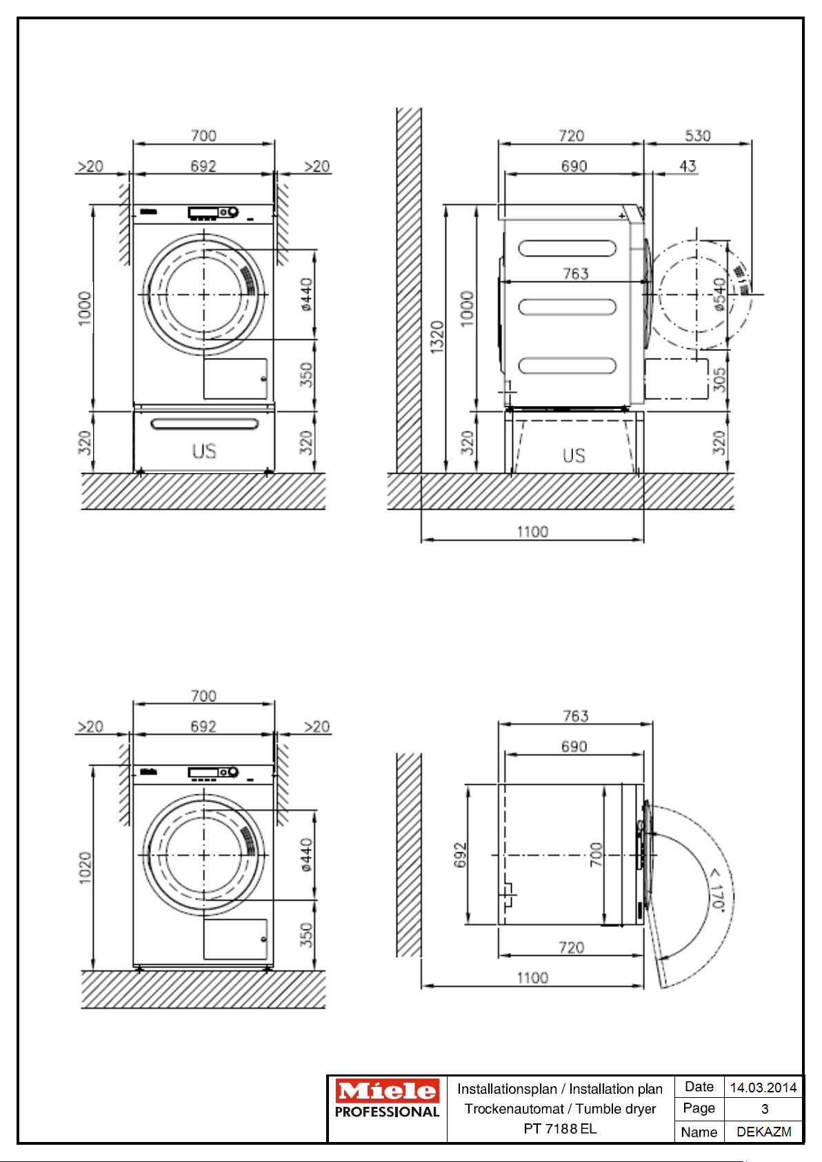
Machine data
Unit width
mm
700
Machine depth
mm
763
Unit height
mm
1020
Casing width
mm
692
Casing depth
mm
690
Minimum width of delivery access to installation site
mm
720
Minimum rear wall gap (measured to front of machine)
mm
1100
Wall gap (to front of machine)
Minimum gap ensures sufficient space for maintenance and
servicing.
mm
900
Net weight
kg
77
Dynamic floor load, max.
N
1000
Average heat dissipation
(dependent on ambient room temperature and programme
selected)
W
450
Sound pressure (re 20 mPA),
workplace-related (at distance of 1 m and height of 1.6 m)
dB (A)
<70
Installation should only be carried out by authorized fitters in accordance with valid regulations!
Observe installation instructions when installing machine! All rights reserved! Measurements in mm.
Technical datasheet: PT 7188 EL
Date: 28.03.2014 Page: 8
 Loading...