

Page 1

Installation instructions
Steam-Sterilizer
PS 1201B V1.0
PS 1202B V1.0
en-CA
M.-Nr. 09 490 990 - 03 /
2015-02-05
Page 2

Contents
Items supplied...................................................................................................................... 3
Unpacking the machine ...................................................................................................... 4
Connecting to services / Ambient conditions................................................................... 5
Connections and installation notes ....................................................................................... 5
Ambient conditions................................................................................................................ 5
Installation notes ................................................................................................................. 6
Back of the machine.............................................................................................................. 6
Water drainage ...................................................................................................................... 6
Mains water ........................................................................................................................... 7
Electrical connection ............................................................................................................. 7
Installation............................................................................................................................ 8
2
Page 3
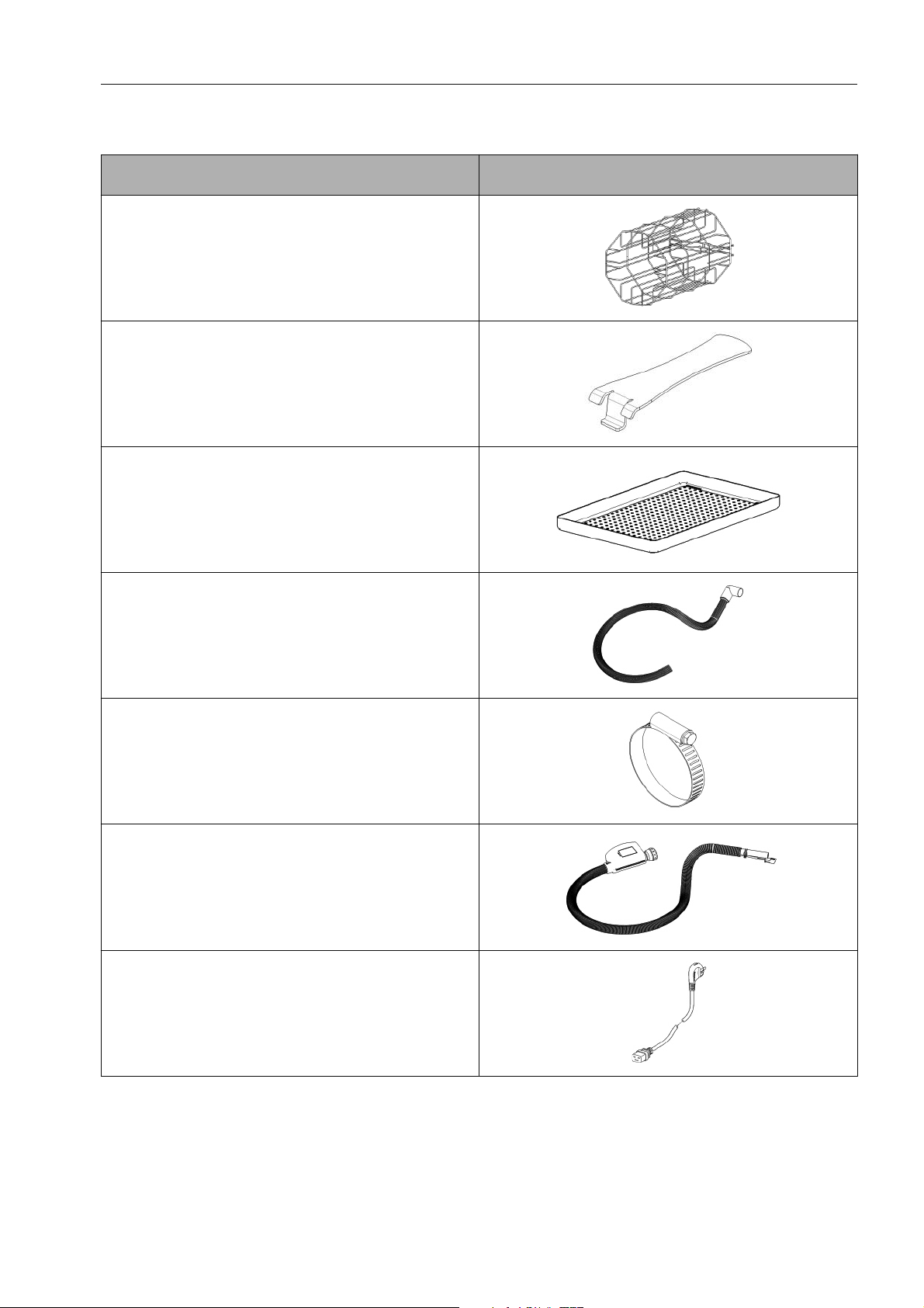
Items supplied
The machine is supplied with the following standard equipment which is packed in the
pressure chamber or included with the transport pack.
Description Illustration
Rack for trays
Tray handle
3 trays
Drain hose
2 hose clips for drain hose
Water inlet hose with water protection de‐
vice (fixed in position)
Power cable
3
Page 4

Unpacking the machine
The steam-sterilizer is supplied in transport packaging. The machine is mounted on a pal‐
let.
ĺ Remove the transport straps from the packaging.
ĺ Lift the lid off the box.
ĺ Remove the wooden frame.
ĺ Remove the outer cardboard sleeve from the machine.
ĺ Remove the cardboard corners.
ĺ Remove the polystyrene corners.
ĺ Remove the protective cover.
Useful tip: With the help of at least one other person, lift the sterilizer out of the remaining
packaging. The machine weighs approx. 63 kg. This is the weight when empty, as the ma‐
chine has not yet been filled with water and / or a load.
Please retain the original packing material after you have unpacked the machine. This
could be useful should you need to move the machine to another location at a later date.
The pressure chamber door is not completely closed during transportation.
ĺ After you have unpacked the machine, remove the tape securing the door.
ĺ Remove the foam from the door.
ĺ Open the door and take the accessories out of the pressure chamber.
The chamber must be empty for the commissioning process.
Do not remove the protective film from the display of a new machine until it has been
connected to the electrical and water supplies.
4
Page 5

Connecting to services / Ambient conditions
Connections and installation notes
Please connect the machine in accordance with the connection data in the following chart:
Installation data
Total connected load 3,200 W
Fuse rating 20 A (surge-proof)
Voltage 208 VAC (+/- 6 %)
Frequency 60 Hz
Water inlet hose
Threaded union 3/4"
Hose length 1.50 m
Flow pressure 150 - 600 kPa (22 - 87 psi)
Drain hose
Connection / Pipe coupling Ø 22.5 mm
Hose length 1.50 m
ɘ The machine must only be connected to the electrical supply with the supplied
NEMA L6-20P plug via a suitable switched socket with an earthing connector. The sock‐
et must be easily accessible after installation in order to disconnect the steam-sterilizer
from the electricity supply.
The drain hose must not exceed 5 metres in length and must be laid at a constant gradient
without kinks. The on-site drainage point must be at least 20 cm below the drain hose con‐
nection point on the machine. To avoid any water damage, please close the faucet at the
end of the working day.
Ambient conditions
Permissible ambient temperature /
Air humidity
Permissible storage temperature /
Air humidity
Maximum height above
sea level
+5 °C to +40 °C / 0 % - 80 %
-10 °C to +60 °C / 0 % - 80 %
2000 m
Minimum air pressure
(ambient pressure)
The machine should not be installed or operated in any area where there is a risk of ex‐
plosion or of freezing conditions existing.
80 kPa (12 psi)
5
Page 6

Installation notes
Back of the machine
Safety valve cover
Mains connection (machine plug connector)
Water inlet (with WPS system) *
Drainage (socket)
*) The fixed water protection device (WPS - Waterproof System) is located at the other end
of the hose.
The drain hose must not exceed 5 meters in length and must be laid at a constant gradi‐
ent without kinks. The on-site drainage point must be at least 20 cm below the drain
hose connection point on the machine.
Water drainage
The drain hose connection point is located at the back of the machine.
ĺ Take the drain hose supplied and push the angled rubber grommet onto the drainage
socket on the machine.
ĺ Secure the drain hose using the clip supplied.
ĺ Connect the drain hose to the on-site drain connection.
Ensure that the drain hose is properly connected and secured to the on-site drainage
point.
6
Page 7

Installation notes
Mains water
The mains water connection point is located at the back of the machine. The machine is
supplied with the water inlet hose already connected.
ĺ Connect the inlet hose to the on-site supply.
Do not use a hose extension. The connection hose is fitted with a special valve that is part
of the machine's waterproof system (WPS). Ensure that the inlet hose is correctly attached
and that the on-site shut-off valve is open.
The steam-sterilizer has an integrated water preparation unit (reverse osmosis unit). This
produces demineralized water for the steam generator.
On no account should the inlet hose be connected to a demineralized water or reverse
osmosis unit. If a water softening unit is being used, make sure it complies with the onsite connection. The grey water inlet must connected to mains water only. The conduc‐
tance level of the mains water must not exceed 375 μS/cm.
Using water containing sediment, particulate matter etc. or water with a high mineral con‐
tent will reduce the performance and useful life of the reverse osmosis unit.
Electrical connection
The electrical connection point is located at the back of the machine.
ĺ Connect the cable to the socket provided on the machine.
ĺ Connect the plug to the on-site socket and ensure that the cable is not twisted or
crimped.
Only use the electrical cable supplied with the machine. Do not use an extension lead.
The machine can be completely disconnected from the electrical supply by withdrawing
the plug from the socket. This should be done prior to cleaning, maintenance or commis‐
sioning of the steam-sterilizer.
ĺ To do this, unplug the power cable from the on-site socket.
The on-site electrical installation must conform to current national standards for the coun‐
try in which the machine is being operated. It must be operated on its own electrical circuit.
Note that the sterilizer may not be connected to a switchable outlet (e.g. Smart Home).
ɘ The machine must be connected to the electrical supply via a suitable switched
socket with earthing connector; otherwise this can result in a electric shock when touch‐
ing the machine casing. The manufacturer cannot accept any responsibility or warranty
claims for incorrect installation.
It is recommended that the machine is connected to a separate spur socket with its own
separate RCD (residual current device). This RCD should be checked regularly by the
operator.
The steam-sterilizer must only be connected to the electrical supply when the casing is
closed.
7
Page 8

Installation
– Install the machine in a well-ventilated room.
– Do not position it beside a sink as splashes of water could cause the machine to short
circuit.
– Keep the machine away from sources of heat.
– The steam-sterilizer must not be installed in areas which are accessible to patients.
– The steam-sterilizer must be installed in the clean area of the preparation room.
– The ventilation grilles in the rear panel must not be covered.
– The service panel must not be blocked.
– The mains switch must be accessible at all times.
– There must be a gap of at least 2 cm between the steam-sterilizer and surrounding surfa‐
ces both above and to the sides.
– Do not place any objects directly next to the cabinet in order to ensure that air can circu‐
late around it freely. Ensure that there is a gap of 7 cm between the back of the machine
and the wall behind it.
Place the steam-sterilizer on a smooth, level surface such as a table or worktop. The sur‐
face it is placed on must be water resistant and heat-resistant to 80 °C. Please note that
the steam-sterilizer when filled and loaded can weigh approx. 80 kg.
Pressure release valve
ɘ The machine must be set up in such a way that no one can stand near the back of
the machine in the event of the pressure release valve being activated. Danger of burn‐
ing and scalding.
Do not use the outer casing of the machine as a resting place for utensils or other ob‐
jects.
8
Page 9

V
Canada
Importer
Miele Limited
Professional Division
161 Four Valley Drive
aughan, ON L4K 4V8
Phone:
Fax:
www.mieleprofessional.ca
professional@miele.ca
Miele Professional Technical Service
Phone:
Fax:
serviceprofessional@miele.ca
1-888-325-3957
1-800-803-3366
1-888-325-3957
1-800-803-3366
Alteration rights reserved / Publication date: 2015-02-05 M.-Nr. 09 490 990 - 03 / 2015-02-05 / 03
Manufacturer
Miele Werk Bürmoos GmbH,
Mielestraße 1, 5111 Bürmoos
Austria
 Loading...