

Page 1
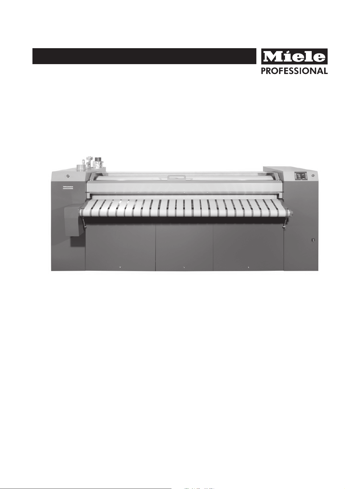
Operating instructions
Rotary ironer
PM 1621
PM 1625
PM 1630
PM 1635
PM 1825
PM 1830
PM 1835
To avoid the risk of accidents or damage to the machine it is
essential to read these instructions before installing,
commissioning and using it for the first time.
en-GB
M.-Nr. 09 404 660
Page 2

2
Page 3

Contents
Warning and Safety instructions...............................................................4
Caring for the environment ...................................................................7
Guide to the machine ........................................................................8
Preparing the laundry.......................................................................12
Condition of laundry .........................................................................12
Preparing the flatwork........................................................................12
Operation .................................................................................13
Preparation for use ..........................................................................13
Language...............................................................................13
Ironing....................................................................................13
Forward roller movement .....................................................................15
Using residual heat..........................................................................15
Stop clock function (optional) ..................................................................15
After ironing: ...............................................................................15
Notes ....................................................................................16
Protecting the padding .......................................................................16
Emergency release if there is a power cut whilst ironing .............................................16
Menu structure .............................................................................17
Cleaning and care ..........................................................................19
Cleaning and waxing the heater plate ...........................................................19
Maintenance ..............................................................................20
Disconnecting (securing) the roller .............................................................20
Leaf-type roller padding ......................................................................21
Heating system .............................................................................22
Wax trap ..................................................................................22
Bearing: ..................................................................................22
Condensate ...............................................................................22
Heat transfer oil for the heater plate.............................................................
Air filter ...................................................................................22
Service ...................................................................................23
Notes for the installer .......................................................................24
Storing the machine .........................................................................24
Operating conditions ........................................................................24
Installing the machine........................................................................24
Electrical connection ........................................................................24
Exhaust ducting for vapour extraction ...........................................................25
Exhaust air volume setting ....................................................................25
Gas connection.............................................................................26
Exhaust ducting ............................................................................26
Steam connection ...........................................................................27
External compressed air connection ............................................................27
Ventilation ducting for the oil reservoir ...........................................................27
Technical data .............................................................................28
22
The rotary ironer must be installed and commissioned by a Miele
service technician or by a Miele authorised Service Dealer.
3
Page 4
Warning and Safety instructions
It is essential to read these instructions.
~
This rotary ironer complies with all relevant safety
requirements. Improper use can, however, lead to
personal injury and damage to property.
To avoid the risk of accidents and damage to the
machine, please read these instructions carefully
before using it for the first time. They contain
important information on its safety, use and
maintenance.
Technical and electrical safety
The machine must not be operated in the same
~
room as dry cleaning machines which use solvents
containing PERs or CFCs.
The ironer must only be operated in a room with a
~
low relative humidity level.
Any removable outer panels must be back in
~
place, and all heated, moving or electrical parts
shielded before the machine is switched on.
Do not damage, remove or bypass the safety
~
features, fixtures and control elements of the
machine.
Do not make any alterations to the machine,
~
unless authorised to do so by Miele.
Do not use a machine with damaged controls or
~
cables. These must be repaired before it is used
again.
Keep these instructions in a safe place and ensure
that they are made available to new users. They
must be made aware of these Warning and Safety
instructions.
Pass these instructions on to any future
users/owners of the machine.
Correct application
The rotary ironer must be used as described in these
instructions and must be checked on a regular basis
to make sure it is functioning correctly. Maintenance
must be carried out when necessary.
Only iron materials with this ironer which are
~
suitable for machine ironing and which were washed
in water.
If the ironer is used in a publically accessible
~
room, it is the supervisor's responsibility to ensure
that suitable measures are in place which enable
operators to use it safely.
The ironer is not intended for outdoor use.
~
Repairs to electrical appliances should only be
~
carried out by a suitably qualified and competent
person in strict accordance with current local and
national safety regulations. Repairs and other work by
unqualified persons could be dangerous. The
manufacturer cannot be held liable for unauthorised
work.
Faulty components must only be replaced by
~
genuine Miele original spare parts. Only when these
parts are fitted can the safety standards of the
machine be guaranteed.
The electrical safety of this machine can only be
~
guaranteed if connected to a correctly installed
earthing system on site. It is most important that this
basic safety requirement is observed and tested
regularly, and where there is any doubt the on-site
electrical system should be inspected by a qualified
electrician. The manufacturer cannot be held liable
for the consequences of an inadequate earthing
system (e.g. electric shock).
The machine is only completely isolated from the
~
electricity supply either when it is switched off at the
isolator switch or the mains fuse has been
disconnected.
4
Page 5

Warning and Safety instructions
Use
This ironer must not be left unattended during use.
~
Children and unauthorised people must be kept
~
away from the rotary ironer.
This machine is not a toy! To avoid the risk of
~
injury, keep children well away and do not allow them
to play on or near the rotary ironer or to operate it
themselves.
The machine can only be used by people with
~
reduced physical, sensory or mental capabilities, or
lack of experience or knowledge, if they are
supervised whilst using it or have been shown how to
use it in a safe way and understand the hazards
involved.
When the ironer is heated up with the heater plate
~
in position, there is an acute danger of burning, if the
edge of the heater plate is touched on the feed out
side.
When ironing double layered items, do not reach
~
in between the layers to straighten out the fabric. This
is extremely dangerous as you may not be able to
extract your hands in time. The same applies when
ironing garments with pockets.
Using accessories
Accessory parts may only be fitted when
~
expressly approved by Miele. If spare parts or
accessories from other manufacturers are used, this
will invalidate the guarantee, and Miele cannot
accept liability.
Notes on the use of this machine
– This ironer must be operated at all times in
accordance with the legal requirements of the
Health and Safety Acts.
– When working with the ironer, always wear close
fitting clothes and keep long hair tied back. Wide
sleeves, apron straps, scarves and ties etc. could
be taken in by the roller.
– Remove rings and bracelets before ironing.
– Smooth out folds as far away from the feed-in on
the feed-in table as possible. Feed pillow cases
and duvet covers into the ironer with the open end
first. Do not take hold of the corners from the
inside. Do not take hold of vest straps or apron
straps etc. from the inside.
Do not iron items with fringes, thin ties and straps
~
etc. These could get tangled in the feed-in belts and
cause a fault.
Ensure the room in which the ironer is being used
~
is sufficiently lit
Keep the area around the ironer free from clutter.
~
Always keep a fire extinguisher accessible in the
~
rare event of textiles igniting.
The ironer may only be used in mobile installations
~
such as ships if a risk assessment of the installation
has been carried out by a suitably qualified engineer.
It is imperative that all local and national safety
regulations concerning the use of this machine are
observed.
– Check daily that safety devices are correctly set.
This way you will avoid the danger of burns,
squashed fingers and even loss of hands.
– Check daily that safety devices are functioning
correctly.
– Make sure that safety features cannot be bridged.
– Before switching to reverse make sure that nobody
is endangered.
– With gas heated machines ensure the room has
sufficient ventilation.
– Switch the machine off before lubricating it.
5
Page 6
Warning and Safety instructions
Gas safety
Safety precautions to take if you smell gas (gas
heated ironers only):
Natural gas usually has no smell of its own. In the UK
a smell is added for safety reasons.
Turn off the gas emergency control valve
^
immediately. This is usually located near the gas
meter.
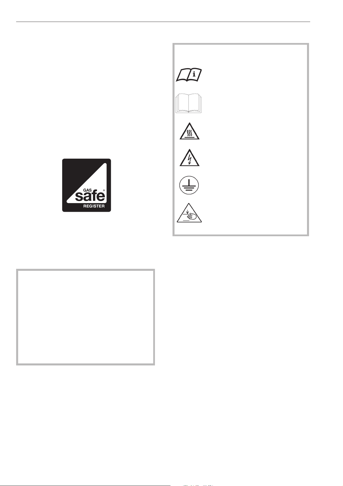
Warning and safety symbols on the machine
Read the operating instructions
^ Do not enter a room with an open flame where
there is the smell of gas.
^ Eliminate all sources of ignition in a safe manner.
Do not smoke, light cigarette lighters or matches.
^ Do not operate electrical lights or switches, i.e. do
not switch them “On” or “Off”.
^ Open all windows and doors to ventilate the area.
^ If the smell of gas persists, evacuate the building.
In the UK you must now: Call the Gas Emergency
Service on 0 800 111 999. For any gas work in
the UK always use a Gas Safe registered
engineer.
In other countries please follow relevant country
specific procedures on gas.
Read the instructions e.g.
installation instructions.
Caution, hot surfaces.
Caution, voltage up to 1000 Volts.
Earth
Danger of squashing
Important: When commissioning and before
concluding any maintenance, conversion or repair
work it is essential that a test for possible leakages
is carried out. All components which carry gas
must be checked, including the gas supply
stopcock and burner jets.
In the U.K. this must be carried out by a Gas Safe
registered engineer. Particular attention should be
paid to the measuring stubs on the gas valve and
the burner. Testing must be carried out with the
burner switched on and switched off.
All personnel working with this machine must be fully
trained in all aspects of its use and safety.
Keep these instructions in a safe and accessible
place.
6
Page 7

Disposal of the packing material
The packaging is designed to protect the machine
during transportation. The transport and protective
packing has been selected from materials which are
environmentally friendly for disposal and should be
recycled.
Rather than just throwing these materials away,
please ensure that they are recycled. Ensure that any
plastic wrappings, bags, etc are disposed of safely
and kept out of the reach of babies and young
children. Danger of suffocation.
Disposing of your old machine
Electrical and electronic machines often contain
materials which, if handled or disposed of incorrectly,
could be potentially hazardous to human health and
to the environment. They are, however, essential for
the correct functioning of your appliance. If handled
or disposed of incorrectly they could be potentially
hazardous to human health and to the environment.
Please do not therefore dispose of it with your general
waste.
Caring for the environment
Please dispose of it at your local community waste
collection / recycling centre, or contact Miele for
advice. Please contact your dealer, your local waste
collection centre or scrap merchant about potential
recycling schemes.
Ensure that it presents no danger to children while
being stored for disposal.
7
Page 8
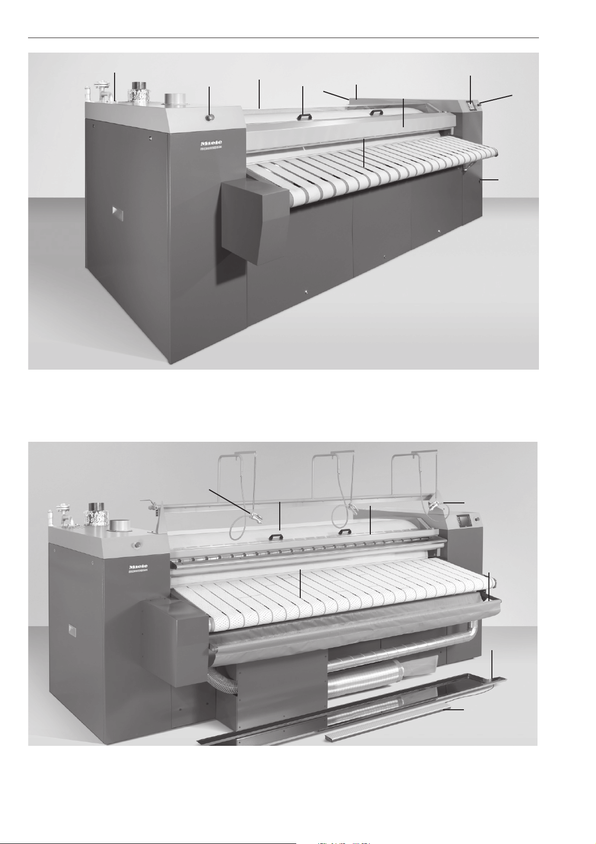
Guide to the machine
5
5
6
4
5
7, 8
3
1
5
2
9
1 Control panel 2 Feed-in table 3 Finger guard
4 Cover/Roller (optional) 5 Emergency stop switch 6 Out-table
7 Main switch 8 Service key switch 9 Compressed air valve
14
10
15
16
17
11
12
13
Optional: 10 Roller cover 11 Laundry table for small items 12 Hygiene guard 13 Foot control bar
14 Textile dampening 15 Return feed
17 Laser feed guide ¡
8
¢ 16 Feed-in table Plus with suction
Page 9

Buttons on the control panel
1 6
2 7
3 8
4 9
5 10
Guide to the machine
"Ironer speed" buttons1=+ 2=-
The revolution speed of the roller can be increased
using + and decreased using - in Universal mode .
The speed set and the actual speed are shown in the
display.
3 l "Start/Stop" button
When this button is pressed, the roller is lowered and
turns or is raised and stops.
4 ! button "Heating on/off"
Button symbols according to heating type:
Electric !
Gas *
When this button is pressed the heating is switched
on or off.
The status is shown in the display.
Steam h
On steam-heated machines, when the h "Steam"
button is pressed, steam pressure is shown in the
display or Automatic heat-up (optional) is activated.
6
# "Menu" button/ one level up in menu
7 X "Programme list" button:
The programme list shows all programmes which can
be selected directly.
8 J "Language" button
For selecting the desired user guidance language.
The language must be available and activated.
9 Y "Scroll down sub menu" button
10 Y "Scroll up sub menu" button
5 , "Quit" button
After a fault has occurred, it can be cleared by
pressing this button.
9
Page 10

Guide to the machine
Display
11 12
13 14
15 16
17 18
20 19 24
25
22
26 27 23
11 Menu
12 Time
13 Ironer
14 Ironer programme number
15 Ironer feed-in target speed
16 Ironer feed-in actual speed
17 Feed-in heater plate target temperature
18 Display heater plate actual temperature
19 Activate suction vacuum table (optional)
20 Activate laser-guided feed-in (optional)
21 Information text
22 User levels
23 Activate high pressure (optional)
24 Laundry return feed (optional)
25 Motor current (only in technician's level)
26 Stop time function (optional)
27 Forward roller movement
Additional symbols in the display:
¤
! Fault
name
programme name
Wax symbol
(please clean and wax the heater plate
10
Page 11

Guide to the machine
Safety features
Master switch
Switches the power supply for the rotary ironer on I or
off 0. This switch can be secured with a padlock if the
rotary ironer needs to be switched off in the event of a
fault or for maintenance work.
Emergency stop switch
Finger guard
If fingers slip between the laundry feed-in table and
the finger guard, the roller will stop turning and lift
immediately. The finger guard is not active if the roller
is running in reverse.
If the finger guard has been activated the machine
can only be restarted by quitting the fault using the
button , and by pressing the l "Start/Stop" button.
One on both the left and right hand columns on the
feed-in side and the output side.
As soon as an emergency stop switch is pressed, the
roller stops turning and lifts immediately.
Only use the emergency stop switch or finger
guard to stop the machine in the case of an
emergency, and not for normal switching off.
To reset an emergency stop switch after it has been
used, turn the switch clockwise.
The finger guard is a safety feature which must be
checked daily for proper functioning before the
machine is used.
Service key switch
During work on the rollers, the ironer or the
compressed air system the roller is lifted into the
repair position. See "Maintenance".
11
Page 12

Preparing the laundry
Condition of laundry
For a good finish the ideal residual moisture level lies
between 25 - 50 %, depending on the condition of the
fabric.
Rinsing the laundry using hot water in the final rinse
helps to reduce the residual moisture level, and the
residual heat in the laundry will help reduce
processing time, saving energy.
Preparing the flatwork
Before starting to iron, laundry should be sorted
according to size and type of fabric.
First iron articles made from:
perlon, nylon etc. temperature 100 - 110°C
then iron
woollens, silks temperature 111 - 150°C
then iron
cottons and linen fabric temperature 151 - 180°C
.
If you want to switch back to ironing at a lower
temperature, reduce the temperature setting and then
wait until the "Heating" indicator light comes on again.
Starched laundry should be ironed last to prevent any
starch residues on the heater plate from affecting
other items of laundry.
Items with buttons should be passed through the
ironer with the buttons facing into the roller padding.
If they face downwards there is a danger of them
being damaged or torn off when the item is passed
through the ironer.
A cloth should be placed over zips, metal buttons
and hooks to protect the heater plate during ironing.
Metal and plastic buckles and very bulky buttons
should not be passed through the ironer.
Warning. Before using the ironer you should
clean the heater plate by running a cloth through
the entire width of the roller.
12
Page 13

Operation
Preparation for use
Open site stopcock for compressed air.
^
Open site stopcock for gas (gas heating only).
^
Open site stopcock for steam (steam heating only)
^
very slowly and only a little way. This is not
necessary with Automatic heat-up.
If steam has accumulated, the stopcock to the
,
machine must only be opened very slowly in
several stages. Turning the steam stopcock
abruptly will damage the machine. This is not
necessary with Automatic heat-up.
^ Switch on the main power supply switch.
The following will appear in the display:
Finger guard test
Activate the finger guard
The following will appear in the display:
Operation
UNIVERSAL 0
Target value Actual value
m/min
°C
Switch heating on
7.4
180
m/min
°C
08:45:58
Operator
Language
If a different user guide language is to be selected:
^ Press J "Language" button
The display will appear in a different language with
each press of the button. The language must be
available and activated.
Ironing
^ Press the heating button.
Button symbols according to heating type:
Electric !, Gas *
(Steam h does not need to be pressed)
0.0
19
The finger guard is a safety feature which must be
checked daily for proper functioning before the
machine is used.
^ Push the finger guard in the direction of the roller.
The following will appear in the display:
Message
Finger guard function
OK
OK
^ Press OK.
The * heating and D fan symbols appear in the
display. The machine is heating up when these
symbols show constantly in the display.
The machine is ready to use when the temperature
set is reached.
The following appears in the display: Ironer ready for
use
^ Start the machine by pressing the l "Start/
Stop" button.
An acoustic signal sounds and the roller is lowered.
Allow the roller to rotate for about 5 minutes to enable
the heat to equalise between the heater plate and the
roller.
,
When the ironer is heated up with the heater
plate in position, there is an acute danger of
burning, if the edge of the heater plate is touched
on the feed out side.
13
Page 14

Operation
To select a programme press the X "Programme
^
list" button.
Programme shortcut
UNIVERSAL PROGRAMME 5
PROGRAMME 1 PROGRAMME 6
PROGRAMME 2 PROGRAMME 7
PROGRAMME 3 WAX PROGRAMME
PROGRAMME 4 PROGRAMME 9
Operator
09:25:55
^ Select the UNIVERSAL programme or select a
suitable programme for the type of laundry.
1/20
Temperature
Operation
UNIVERSAL 0
Target value Actual value
m/min
°C
Switch heating on
Press the display field "Target value °C" highlighted
^
7.4
180
m/min
°C
08:45:58
0.0
Operator
grey.
180
123
456
789
.0
# <=
OK
19
Temperature, ironer speed and pressure (optional)
can all be adjusted in the UNIVERSAL programme.
Temperature, ironer speed, pressure
These parameters can only be adjusted in the
Universal programme.
Target and actual values are shown in the display.
Adjust the heater plate temperature according to
laundry type.
Material Temperature range
Polyester / artificial silk 100 - 110°C
Silk / wool 111 - 150°C
Cottons / linen 151 - 180°C
^ Enter the required temperature into the input field
and confirm with OK.
The temperature cannot be altered for steam
heated ironers.
Temperature adjustment is optional.
Speed of ironer
^ Adjust the
ironer speed according to laundry type
and residual moisture using the + or - buttons.
The ironer speed can also be altered via the display
field "Ironer speed" highlighted grey.
^ Enter the required ironer speed into the input field
and confirm with OK.
Pressure
£ (optional)
Roller pressure can be increased by pressing the
control field in the display. The field will then turn
green.
14
Page 15

Operation
Laundry feed-in
Feed-in Plus table with suction (optional)
Feed-in belts make it easier to feed laundry into the
ironer.
^ Laundry should be placed parallel to the roller at
the start of the feed-in table. Make sure it lies flat
across the feed-in belts as it goes in.
Do not restrict ironing of smaller articles to any one
part of the roller. Make use of the whole roller width.
Forward roller movement
The forward roller movement (at the feed-in belts)
tensions the laundry as it is drawn in. Standard value
- 5%. Pressing the control field changes the forward
roller movement.
Equal
=
1 5%
2 10 %
3 15 %
Using residual heat
(not steam-heated machines)
The heating can be switched off before ironing is
finished to make use of residual heat in the heater
plate. To maintain the same standard of laundry
finish, the ironer speed is slowed down automatically.
Time remaining until the ironer switches off
automatically is shown in the display.
Stop clock function (optional)
By pressing the + "Stop clock" field, the stop clock
is started and the field turns green.
If the stop clock is stopped by pressing the
clock" field, the ironing process stopped or the
programme changed, the stopped time is saved.
Completed ironer times are shown on the 2nd display
page (X button) with date, time and programme.
The stop times can be deleted by pressing the
field.
+ "Stop
reset
Foot control bar (optional)
^ The foot control bar
of laundry or in the event of feed-in errors.
The roller will stop.
^ The roller starts again as soon as the foot control is
released.
The ironed laundry can be very hot when it comes
off the ironer.
Pick-off bands
can be used for smaller items
After ironing:
Allow the roller to run for approx. 5 minutes with the
heating switched off to allow the padding to dry out.
Switch the ironer off using the l "Start/Stop" button
^
For gas or steam-heated machines, close the
^
on-site stopcock.
^ Switch off at the main switch on the rear of the
right-hand column.
Allow the ironed laundry to cool down before
,
packing or stacking it. Hot laundry could self-ignite
and cause a fire.
The pick-off bands are used for picking laundry off
the roller.
15
Page 16

Notes
Protecting the padding
Switch the machine off during pauses in ironing to
prevent damage to the padding.
It is very important to avoid running the ironer
without passing laundry through it.
Do not restrict ironing smaller articles to any one part
of the roller; make use of the whole roller width. This
way an equal amount of heat is obtained from the
heater plate and the roller padding is protected from
uneven use.
Emergency release if there is a power cut
whilst ironing
The roller lifts automatically in the event of a power
cut.
Once power is restored, the ironer is switched back
on by pressing the l "Start/Stop" button.
16
Page 17

Menu structure
Notes
Main menu
via service key
Operation Heater
Messages Report history
Programmes Process programme
Reset programme
Statistics Operating hours
Report counter
(Number)
Service Parameters Interfaces
Data backup Programmes
Report counter
(Duration)
Set-up
Diagnosis Hardware
Event log
System log
Languages
Settings Display
Date / time
PIN
Info
Service level is PIN-protected and is accessible only to Miele service personnel.
Technician's level is also PIN-protected. The PIN is: 0189
17
Page 18

Notes
Access to the Technician's level
Operator
Service
Technician
^ Press Technician.
^ Input PIN (0189) and press OK.
The operation menu appears in the display:
Operation
UNIVERSAL 0
Target value Actual value
m/min
°C
Switch heating on
^ Press
# "Menu" button.
7.4
180
m/min
°C
08:45:58
Operator
The following menus are displayed:
Main menu
Operation
Messages
Programmes
Statistics
Service
Messages
– Message history
All messages are displayed here.
Programmes
– Process programme
Here you can give a programme a name and
number. Roller speed, roller lead, heater plate
temperature, pressure (optional) can be set.
– Reset programme
A programme can be deleted here.
Statistics
–
Operating hours
Total number of operating hours.
0.0
19
Service
Parameters
Interfaces
–
IP address, Subnet screen, Std. Gateway
Machine
–
Roller lead 5 %
Ironer off when foot switch operated for 180 s
Trough cleaning time interval 8 h
Data backup
– Programmes
Programmes saved to USB, Compact Flash
Diagnosis
– Hardware
Slots ST1-ST15forcontrol hardware in- and
outputs can be checked here.
Active slots are highlighted in green. If they are red,
there is an error.
– Event log
Technician actions carried out, e.g. "Password level 2
selected" are marked with date and time.
– System log
System messages are shown here which in the case
of a fault can be passed on to Miele Service.
Languages
The operating language is activated or deactivated
here.
Settings
– Display
Display brightness can be adjusted here.
– Date / time
Date, time and summer- and wintertime can be
adjusted here.
– PIN
The password for the Technician's level can be
changed here.
Info
Serial number of the machine, AR, software status,
version, node number, CPU temperature , control
battery status.
–
Report counter
Number of messages displayed, e.g. emergency
stop, finger guard, cover.
–
Report counter
Number and time of messages.
18
Page 19

Cleaning and care
Cleaning and waxing the heater plate
Regular cleaning and maintenance of the heater plate
is essential for ensuring consistent ironing results, as
well as for protecting the motor and the roller cover. It
also helps to prolong the life of the machine.
This machine is fitted with a steel heater plate.
Deposits (starch and detergent residues) can build
up on the heater plate.
Do not use any abrasive cleaning agents or
,
sandpaper .
The steel heater plate must only be cleaned using
cleaning agents approved by the manufacturer.
Use the cleaning set. It consists of a cleaning cloth, a
waxing cloth and wax. This set is available to order
from Miele as an accessory.
When the message
appears in the display (optional), select Waxing
programme 8. The wax symbol
display. It will go out again when the waxing
programme is finished.
Clean the heater plate before waxing.
Please clean and wax plate
¤ will appear in the
Feed-in direction
^ To wax, sprinkle wax into the pockets of the waxing
cloth
Use the wax sparingly to avoid the roller cover
becoming too smooth.
^ Fold over the top third of the cloth to close it.
^ Feed the wax cloth through the hot ironer.
^ Feed the cloth into the machine repeatedly, moving
along the whole width of the roller from left to
right.
If
Please clean and wax plate does not appear in the
display (optional):
Clean the heater plate at the start of the working day
and use the waxing cloth without wax.
Clean and wax the heater plate according to laundry
throughput.
^ Select the waxing programme.
(Temperature setting 180°C, low roller speed, high
contact pressure.)
Feed-in direction
^ Leave the waxing programme. Feed in a damp
cloth across the entire roller width using the
universal programme to remove any wax and
starch residues.
Pick-off bands
The tips of the pick-off bands need to be cleaned
occasionally to remove any build-up of residues such
as starch.
Important: Feed in the steel wool cleaning strips face
downwards, towards the heater plate.
^
Feed the cloth into the machine repeatedly, moving
along the whole width of the roller from left to
right.
The heater plate should always be waxed after it has
been cleaned.
^ Mark the position of the pick-off segment and
dismantle the pick-off segment. Do not use the
rotary ironer without the pick-off bands fitted.
Danger of crushing.
^
Relocate it to its original position after cleaning.
19
Page 20

Maintenance
Maintenance must be carried out only by Miele
,
Service or other authorised suitably qualified and
competent personnel.
Disconnecting (securing) the roller
During work on the roller, the ironer or the
compressed air system the roller is lifted into the
repair position leaving a space between the roller and
the heater plate.
^ Switch on the main power supply switch.
^ Set the service switch to I.
The following appears in the display on user level:
Open both service panels on the side columns.
^
The roller is in the raised position.
Set-up
m/min
5,0
Position
14:36
START
Operator
The roller is in the raised position.
Press
Position: Lower roller, raise roller.
Press START: The roller only rotates whilst this
control is touched.
In technician's level inputting the PIN brings up the
following in the display:
Set-up
14:36
^ Loosen the screws securing the safety bolts on
both sides.
^ Push the safety bolts into the holes and tighten the
screws back up again.
^ Remove the cover plate if necessary.
Work on the roller, heater plate or compressed air
system can now be carried out.
To secure the roller again:
20
m/min
START
5,0
Position
Rotation direction
Technician
^ Loosen the screws securing the safety bolts on
both sides.
^ Pull the safety bolts back out of the holes on both
sides and tighten the screws back up.
^ Close both service panels on the side columns.
Page 21

Maintenance must be carried out only by Miele
,
Service or other authorised suitably qualified and
competent personnel.
Roller diameter
PM 1621, PM 1625,
PM 1630, PM 1635
Maintenance
Max. diameter (with
cover) 600 mm
Removal and replacement of the roller
plate cover should be undertaken only by
Miele Service or other authorised,
suitably qualified and competent
personnel.
Leaf-type roller padding
Only iron articles up to max. 3 mm thick. Bulky
fabrics, protruding buttons, curtain weights etc.
could damage the leaf-type padding.
After commissioning
It is advisable approx. 40 operating hours after
commissioning to cut back the overlap of the roller
cover (which has occurred through stretching) to
about 30 mm, and then to brush out about 15 mm of
this using a wire brush.
This will help to prevent damp streaks and pressure
imprints. The roller padding must be the same
thickness across the whole width of the roller, and fit
firmly up to the heater plate.
PM 1825, PM 1830,
PM 1835
Max. diameter (with
cover) 800 mm
Discolouration of the roller cover
Some discolouration of the roller cover from light to
dark brown is normal.
To minimise discolouration:
– Always use the complete width of the roller.
– Space out smaller items, and do not always iron
them in the same place.
– Switch the machine off during pauses in ironing.
21
Page 22

Maintenance
Heating system
Errors or faults in the heating system are shown in the
display and must only be rectified by Miele Service or
other authorised, suitably qualified and competent
personnel.
Gas heated machines
The interior of the machine, the burner cavity and the
burner should be checked regularly for any build-up
of fluff and cleaned as required by a Miele service
technician or suitably qualified and competent
person.
To ensure the correct performance of the
,
machine and to prevent the risk of faults and fire
risk it is important to check the machine and carry
out maintenance on a regular basis.
Wax trap
The wax trap is located in the exhaust air ducting
connection for vapour extraction. Condensate and
wax flows back along a tube into a drip cup located
underneath the left-hand column.
Condensate
Accumulated condensate from the oil reservoir on the
left-hand column must be drained once a year.
2
1
^ To do this, open the drain valve (1) with an SW 11
spanner and collect the condensate.
Filling connection (2) for oil.
Heat transfer oil for the heater plate
An analysis of the heat transfer oil must be carried
out once a year.
^ Check the tube (see arrow) regularly for blockages.
^ Remove and check the drip cup. Dispose of any
wax in an environmentally friendly way.
Bearing:
Lubrication (applies for all bearings):
at least once a year.
Air filter
Air filter on the fan for the control box at the back of
the right-hand column.
^ Remove the grille sideways (see arrow) and clean
the paper insert once a week with a vacuum
cleaner.
22
Page 23

Service
In the event of any faults please contact the Miele
Service Department.
When contacting the Service Department, please
quote the Model, Serial number (SN:) and Material
number (M.Nr).
See data plate for details.
Only use spare Parts approved by the manufacturer.
When ordering spare parts please quote the Model,
Serial number (SN:) and Material number (M.Nr).
Maintenance
23
Page 24

Notes for the installer
The rotary ironer must be commissioned by a
Miele authorised service technician.
The machine must not be operated in the same room
as dry cleaning machines which use solvents
containing PERs or CFCs. Escaping vapours could
ignite on the motor and form hydrochloric acid which
can have dangerous consequences.
Storing the machine
The following conditions must be observed for
transport and storage:
Temperature: minimum -25°C to maximum 55°C
Air humidity: minimum5%tomaximum 75 %,
non-condensing
Maximum storage duration: 2 years
Electrical connection
Electrical connection may only be carried out by a
suitably qualified technician in strict accordance with
local and national safety regulations (BS 7671 in the
UK).
When installing a residual current device (RCD), a
type B (sutable for detecting high frequency AC and
DC earth leakage current) must be installed.
This ironer conforms to the requirements of
EN 60204-1.
The machine is supplied ex-works for
400 V~ 3N 50 Hz.
See data plate for details.
Connection should be made via a suitable isolator
which complies with local and national safety
regulations.
Operating conditions
Operating conditions as specified in EN 60204
generally apply.
Temperature and relative air humidity
Temperature: 5°C - 40°C
Relative air humidity: 10% - 85%
At an ambient temperature of 21°C (40°C) the
maximum permissible relative air humidity is 70%
(50%).
Installing the machine
This machine is classified as Class A. It can cause
radio interference if set up in living areas.
The machine is transported to the installation location
in packaging.
Remove all packaging prior to commissioning.
4 points for lifting gear such as straps and hooks are
located near the top of the side columns.
When setting the machine leave at least 600 mm
space at either side of the machine so that the side
panels are accessible.
For hard-wired machines, connection should be
made via a suitable mains switch with all-pole
isolation which when in the off position ensures a 3
mm gap between all open contacts. These include
circuit breakers, fuses and relays (IEC/EN 60947).
The socket connection or isolator switch should be
easily accessible for disconnecting the machine from
the electricity supply for service or maintenance work.
If the machine is isolated from the electrical supply
adequate measures must be taken to ensure that it
cannot be reconnected to the electrical supply until
all work has been carried out.
Leave a minimum of 1.5 m free space in front of and
behind the machine to prevent surrounding materials
(furnishings, walls) from becoming too hot. There
should be a minimum space of 1 meter above the
machine.
Levelling and securing the ironer
Use a spirit level and the adjustable feet to align the
machine.
Tighten the counter nuts on each foot up against the
machine columns.
24
The wiring diagram and connection box are located
in the right hand side column. Mains connection is via
the main switch which is located in the control box.
Equipotential bonding
The leakage current of this machine is more than 10
mA. Equipotential bonding should be carried out.
Connection should be made in accordance with
the wiring diagram, the installation diagram and
the installation. It is important to follow all of these
carefully to ensure the machine is connected
correctly.
Page 25

Notes for the installer
After connecting the machine
If the phase order of the electrical connection is
incorrect the exhaust fan in the left-hand column
turns in the wrong direction.
Disconnect the machine from the mains and change
two phases over.
Check the exhaust fan rotation. When looking at the
motor, the exhaust fan should turn in an
anti-clockwise direction.
To prevent the build-up of condensation and wax the
machine is fitted with a wax trap. The tube for
disposal of wax and condensate is located in the
left-hand column and must be checked regularly for
blockages.
Ensure that there is sufficient ventilation in the room
where the ironer is installed.
If the exhaust is ducted into the outside air, the end of
the duct should be protected against the elements.
An exhaust system ducted into the open air must be
situated in such a way that it does not cause a
nuisance.
The on-site ducting system and the exit point to the
outside must be checked on a regular basis for a
build-up of fluff and cleaned, if required.
Exhaust air volume setting
The exhaust air outlet is located in the left-hand
column
Exhaust ducting for vapour extraction
Follow the fitting instructions supplied.
The exhaust ducting must not be directed into any
chimney or flue which is used by gas, solid fuel or oil
fired appliances. It must also be kept separate from
any exhaust system leading from a tumble dryer.
The warm, moist exhaust air should be discharged to
the outside air by the shortest route possible.
Air throughput is greatest on the lowest screw setting
(see diagram) and can be reduced by turning the
screw to 90°. The ideal setting is reached when the
roller dries out sufficiently to leave no water spots
either on the covering or on flatwork with the lowest
throughput of air. If the air throughput is too high the
roller will cool down too much, thus reducing the
ironer's performance.
To ensure optimum flow, the ducting should be laid
with as few bends as possible and all connections
and joins should be airtight.
The connection point for the exhaust ducting is
located on the top of the left hand column and has a
diameter of 150 mm.
25
Page 26

Notes for the installer
Gas connection
Gas connection work must be carried out by an
authorised fitter in accordance with local and national
safety regulations including gas regulations, building
regulations and fire regulations. This must be a Gas
Safe registered technician in the UK.
The gas group to which the machine has been set at
the factory is given on the Gas Data label on the rear
of the machine.
Follow the fitting instructions supplied.
After setting up and connecting the machine
,
successfully ensure that all removable outer
panels are correctly fitted back into position.
Do not attempt to repair or work on gas-heated
,
appliances yourself. Repairs must only be carried
out by an authorised technician to ensure safety.
In the event of a fault please contact the Miele
Service Department.
Exhaust ducting
The exhaust ducting to be installed on site must not
be directed into any chimney which is used by gas,
solid fuel or oil fired appliances.
The connection point for the exhaust ducting is
located on the top of the left hand column and has a
diameter of 125 mm.
,Ensure that there is sufficient ventilation in the
room where the ironer is installed.
Follow the fitting instructions supplied.
26
Page 27

Notes for the installer
Steam connection
Steam connection must only be carried out by an
authorised installer.
To avoid unnecessary heat tension ensure that
heating up is even (no sudden bursts of steam). If
steam has accumulated, the stopcock to the machine
must only be opened very slowly in several stages
Turning the steam stopcock abruptly will
,
damage the machine.
Steam and condensation ducting connections
Machine connection flange DIN 2635, DN 32.
Minimum nominal diameter of the pipe (DIN 2402) is
DN40.
Follow the fitting instructions supplied.
External compressed air connection
The connection (10 mm) for the compressed air hose
is located on the front of the right-hand column. The
duct is located at the back of the right-hand column.
The air operating pressure in the compressed air
system of the machine must remain constant during
functional operation.
Min. 6 to max. 10 bar at 80 l/h consumption.
The compressor must exceed the consumption by
20-30%.
Ventilation ducting for the oil reservoir
Installation suggestion
1 Stop cock
2 Condensate drain
3 Dirt trap
4 Stop cock
Machine connection flange DIN 2633, DN 32.
5 Non-return valve
These components are installed on-site.
Lay the pipes so that the operating components of
the ironer remain accessible.
Insulate the pipes against heat loss (also serves as
personnel protection insulation). Protect insulation
material from moisture.
27
Page 28

Technical data
PM 1621E/G PM 1625E/G/D PM 1630E/G/D PM 1635E/G/D
Height in mm 1970/1970 1970/1970/1630 1970/1970/1630 1970/1970/1630
Width in mm 3290 3690 4190 4690
Depth in mm 1840 1840 1840 1840
Weight in kg 2390/2600 2550/2760/2600 2760/2970/2830 2950/3170/3050
Voltage See data plate
Connected load See data plate
Fuse rating See data plate
Test certificates
awarded
Max. load bearing
in operation in N
Steam pressure in bar 10
Gas pressure in mbar 14 - 300
Air pressure Min. 6 to max. 10 bar at 80 l/h consumption.
Product safety standard EN 60204-1, EN ISO 10472-1, EN ISO 10472-5
24000/26100 25600/27800/25600 27800/29900/27800 29700/31900/30000
See data plate
Emission sound
pressure level in
dB (A), EN ISO 11204
Sound power level in
dB (A), EN ISO 9614-2
PM 1825E/G/D PM 1830E/G/D PM 1835G/D
Height in mm 1970/1970/1630 1970/1970/1630 1970/1630
Width in mm 3690 4190 4690
Depth in mm 2044 2044 2044
Weight in kg 2990/3200/3280 3250/3470/3600 3730/3900
Voltage See data plate
Connected load See data plate
Fuse rating See data plate
Test certificates awarded See data plate
Max. load bearing
in operation in N
Steam pressure in bar 10
Gas pressure in mbar 14 – 300
Air pressure Min. 6 to max. 10 bar at 80 l/h consumption.
Product safety standard EN 60204-1, EN ISO 10472-1, EN ISO 10472-5
Emission sound pressure
level in
dB (A), EN ISO 11204
Sound power level in
dB (A), EN ISO 9614-2
30200/32300/32200 32800/35100/35400 37700/38300
66
66
28
Page 29

29
Page 30

United Kingdom:
Miele Co. Ltd.
Fairacres, Marcham Road, Abingdon, Oxon, OX14 1TW
Customer Contact Centre Tel.: 0330 160 6600
E-mail: mielecare@miele.co.uk
Internet: www.miele.co.uk
Alteration rights reserved/2615
M.-Nr. 09 404 660 / 03
 Loading...