

Page 1

Operating instructions
Rotary ironer
PM 1318
PM 1418
PM 1421
To avoid the risk of accidents or damage to the machine it is en - GB, AU, NZ
essential to read these instructions before installing,
commissioning and using it for the first time.
M.-Nr. 07 185 753
Page 2

2 M.-Nr. 07 185 753
Page 3

Contents
Warning and Safety instructions . . . . . . . . . . . . . . . . . . . . . . . . . . . . . . . . . . . . . . . . . . . . . . . 4
Caring for the environment . . . . . . . . . . . . . . . . . . . . . . . . . . . . . . . . . . . . . . . . . . . . . . . . . . . . 7
Guide to the machine. . . . . . . . . . . . . . . . . . . . . . . . . . . . . . . . . . . . . . . . . . . . . . . . . . . . . . . . . 8
Preparing the laundry . . . . . . . . . . . . . . . . . . . . . . . . . . . . . . . . . . . . . . . . . . . . . . . . . . . . . . . 12
Condition of linen . . . . . . . . . . . . . . . . . . . . . . . . . . . . . . . . . . . . . . . . . . . . . . . . . . . . . . . . . . . . 12
Preparing the flatwork . . . . . . . . . . . . . . . . . . . . . . . . . . . . . . . . . . . . . . . . . . . . . . . . . . . . . . . . 12
Operation . . . . . . . . . . . . . . . . . . . . . . . . . . . . . . . . . . . . . . . . . . . . . . . . . . . . . . . . . . . . . . . . .13
Ironing . . . . . . . . . . . . . . . . . . . . . . . . . . . . . . . . . . . . . . . . . . . . . . . . . . . . . . . . . . . . . . . . . . . . 13
After ironing . . . . . . . . . . . . . . . . . . . . . . . . . . . . . . . . . . . . . . . . . . . . . . . . . . . . . . . . . . . . . . . . 14
Additional safety features . . . . . . . . . . . . . . . . . . . . . . . . . . . . . . . . . . . . . . . . . . . . . . . . . . . . 15
Protection of the motor and the roller cover. . . . . . . . . . . . . . . . . . . . . . . . . . . . . . . . . . . . . . . . 15
If there is a power cut whilst ironing. . . . . . . . . . . . . . . . . . . . . . . . . . . . . . . . . . . . . . . . . . . . . .15
Laundry return-feed machines . . . . . . . . . . . . . . . . . . . . . . . . . . . . . . . . . . . . . . . . . . . . . . . . 16
Laundry return-feed . . . . . . . . . . . . . . . . . . . . . . . . . . . . . . . . . . . . . . . . . . . . . . . . . . . . . . . . . . 16
Cleaning and care . . . . . . . . . . . . . . . . . . . . . . . . . . . . . . . . . . . . . . . . . . . . . . . . . . . . . . . . . . 17
Waxing the heater plate . . . . . . . . . . . . . . . . . . . . . . . . . . . . . . . . . . . . . . . . . . . . . . . . . . . . . . . 17
Cleaning the heater plate. . . . . . . . . . . . . . . . . . . . . . . . . . . . . . . . . . . . . . . . . . . . . . . . . . . . . . 17
Heater plate service position . . . . . . . . . . . . . . . . . . . . . . . . . . . . . . . . . . . . . . . . . . . . . . . . . . . 18
Winding on the steel wool roller padding. . . . . . . . . . . . . . . . . . . . . . . . . . . . . . . . . . . . . . . . . . 19
Leaf-type roller padding. . . . . . . . . . . . . . . . . . . . . . . . . . . . . . . . . . . . . . . . . . . . . . . . . . . . . . . 20
Symbols on the data plate. . . . . . . . . . . . . . . . . . . . . . . . . . . . . . . . . . . . . . . . . . . . . . . . . . . . 22
Notes for the installer. . . . . . . . . . . . . . . . . . . . . . . . . . . . . . . . . . . . . . . . . . . . . . . . . . . . . . . . 23
Setting up the machine . . . . . . . . . . . . . . . . . . . . . . . . . . . . . . . . . . . . . . . . . . . . . . . . . . . . . . . 23
Electrical connection . . . . . . . . . . . . . . . . . . . . . . . . . . . . . . . . . . . . . . . . . . . . . . . . . . . . . . . . . 25
Exhaust ducting for vapour extraction . . . . . . . . . . . . . . . . . . . . . . . . . . . . . . . . . . . . . . . . . . . . 26
Gas connection . . . . . . . . . . . . . . . . . . . . . . . . . . . . . . . . . . . . . . . . . . . . . . . . . . . . . . . . . . . . . 27
Exhaust ducting . . . . . . . . . . . . . . . . . . . . . . . . . . . . . . . . . . . . . . . . . . . . . . . . . . . . . . . . . . . . . 27
Guarantee . . . . . . . . . . . . . . . . . . . . . . . . . . . . . . . . . . . . . . . . . . . . . . . . . . . . . . . . . . . . . . . . .28
The rotary ironer must be installed and commissioned
by a Miele service technician or by a Miele authorised
Service Dealer.
M.-Nr. 07 185 753 3
Page 4

Warning and Safety instructions
It is essential to read these instructions.
This rotary ironer complies with all
relevant safety requirements. Improper
use can, however, lead to personal injury
and damage to property.
To avoid the risk of accidents and
damage to the machine, please read
these instructions carefully before using it
for the first time. They contain important
information on its safety, use and
maintenance.
Keep these instructions in a safe place
and ensure that they are made available
to new users. They must be made aware
of these Warning and Safety instructions.
Pass these instructions on to any future
users/owners of the machine.
Technical and electrical safety
This machine must not be operated in
the same room as dry cleaning
machines which use solvents containing
PERs or CFCs.
The ironer must only be operated in a
room with a low relative humidity level.
Any removable outer panels must be
back in place, and all heated, moving or
electrical parts shielded before the machine
is switched on.
Do not damage, remove or bypass the
safety features, fixtures and control
elements of the machine.
Do not make any alterations to the
machine, unless authorised to do so by
Miele.
Do not use a machine with damaged
controls or cables. These must be
repaired before it is used again.
Correct application
The rotary ironer must be used as described
in these instructions and must be checked
on a regular basis to make sure it is
functioning correctly. Maintenance must be
carried out when necessary.
Only iron materials with this ironer which
are suitable for machine ironing and
which were washed in water.
If the ironer is used in a publically
accessible room, it is the supervisor's
responsibility to ensure that suitable
measures are in place which enable
operators to use it safely.
The ironer is not intended for outdoor
use.
Repairs to electrical appliances should
only be carried out by a suitably
qualified and competent person in strict
accordance with current local and national
safety regulations. Repairs and other work
by unqualified persons could be dangerous.
The manufacturer cannot be held liable for
unauthorised work.
Faulty components must only be
replaced by genuine Miele original spare
parts. Only when these parts are fitted can
the safety standards of the machine be
guaranteed.
The electrical safety of this machine can
only be guaranteed if connected to a
correctly installed earthing system on site. It
is most important that this basic safety
requirement is observed and tested
regularly, and where there is any doubt the
on-site electrical system should be
inspected by a qualified electrician. The
manufacturer cannot be held liable for the
consequences of an inadequate earthing
system (e.g. electric shock).
The machine is only completely isolated
from the electricity supply either when it
is switched off at the isolator switch or the
mains fuse has been disconnected.
4 M.-Nr. 07 185 753
Page 5

Warning and Safety instructions
Use
This ironer must not be left unattended
during use.
This machine is not a toy! To avoid the
risk of injury, keep children well away
and do not allow them to play on or near the
rotary ironer or to operate it themselves.
This machine can only be used by
people with reduced physical, sensory
or mental capabilities, or lack of experience
or knowledge, if they are supervised whilst
using it or have been shown how to use it in
a safe way and understand the hazards
involved.
When the ironer is heated up with the
heater plate in position, there is an acute
danger of burning, if the edge of the heater
plate is touched on the feed-out side.
When ironing double layered items, do
not reach in between the layers to
straighten out the fabric. This is extremely
dangerous as you may not be able to extract
your hands in time. The same applies when
ironing garments with pockets.
Ironers with belt feed:
Do not iron items with fringes, thin ties
and straps etc. These could get tangled in
the feed-in belts and cause a fault.
Ensure the room in which the ironer is
being used is sufficiently lit.
Always keep a fire extinguisher
accessible in the rare event of textiles
igniting.
Notes on the use of this machine
This ironer must be operated at all times in
–
accordance with the legal requirements of
the Health and Safety Acts.
Persons with especially slim fingers should
–
only work at the receiving side and not at
the feed-in.
When working with the ironer, always wear
–
close fitting clothes and keep long hair
tied back. Wide sleeves, apron straps,
scarves and ties etc. could be taken in by
the roller.
Remove rings and bracelets before
–
ironing.
Smooth out folds as far away from the
–
feed-in on the feed-in table as possible.
Feed pillow cases and duvet covers into
the ironer with the open end first. Do not
take hold of the corners from the inside.
Do not take hold of vest straps or apron
straps etc. from the inside.
– Check daily that safety devices are
correctly set. This way you will avoid the
danger of burns, squashed fingers and
even loss of hands.
– Check daily that safety devices are
functioning correctly.
–
Make sure that safety features cannot be
bridged.
–
Before switching to reverse make sure that
nobody is endangered.
This ironer may only be used in mobile
installations such as ships if a risk
assessment of the installation has been
carried out by a suitably qualified engineer.
It is imperative that all local and national
safety regulations concerning the use of
this machine are observed.
Using accessories
Accessory parts may only be fitted when
expressly approved by Miele. If spare
parts or accessories from other
manufacturers are used, this will invalidate
the guarantee, and Miele cannot accept
liability.
M.-Nr. 07 185 753 5
–
With gas heated machines ensure the
room has sufficient ventilation.
–
Switch the machine off before lubricating
it.
Page 6

Warning and Safety instructions
Gas safety
Safety precautions to take if you smell
gas (gas heated ironers only):
Natural gas usually has no smell of its own.
In the UK a smell is added for safety
reasons.
Turn off the gas emergency control valve
^
immediately. This is usually located near
the gas meter.
Eliminate all sources of ignition in a safe
^
manner. Do not smoke, light cigarette
lighters or matches.
Do not operate electrical lights or
^
switches, i.e. do not switch them “On” or
“Off”.
Open all windows and doors to ventilate
^
the area.
If the smell of gas persists, evacuate the
^
building.
In the UK you must now:
^ Call the Gas Emergency Service on 0 800
111 999.
For any gas work in the UK always use a
Gas Safe registered engineer.
In other countries please follow relevant
country specific procedures on gas.
Important: Before signing off any
commissioning, maintenance, conversion
or repair work as finished, all gas
pipework from the manual isolating valve
to the burner nozzles must be checked for
gas soundness. Particular attention
should be paid to the test points on the
gas valve, the supply pressure monitor
and the burner. Checks should be made
with the burner both on and off.
All personnel working with this machine must
be fully trained in all aspects of its use and
safety.
Keep these instructions in a safe and
accessible place.
6 M.-Nr. 07 185 753
Page 7

Disposing of the packing material
The packaging is designed to protect the
machine during transportation. The transport
and protective packing has been selected
from materials which are environmentally
friendly for disposal and should be recycled.
Ensure that any plastic wrappings, bags, etc
are disposed of safely and kept out of the
reach of babies and young children. Danger
of suffocation.
Disposing of your old machine
Electrical and electronic machines often
contain materials which, if handled or
disposed of incorrectly could be potentially
hazardous to human health and to the
environment. They are, however, essential
for the correct functioning of your machine.
Please do not therefore dispose of it with
your general waste.
Caring for the environment
Please dispose of it at your local community
waste collection / recycling centre, or
contact Miele for advice.
Please ensure that it presents no danger to
children whilst awaiting disposal.
M.-Nr. 07 185 753 7
Page 8

Guide to the machine
7
6
5
4
1
7
3
2
8
1 Control panel
2 Laundry shelf
3 Feed-in table
4 Finger guard
5 Roller
6 Out-tabling
7 Emergency stop switch
8 Foot control bar
8 M.-Nr. 07 185 753
Page 9

1 2 3 4
1 Speed selector
2 Temperature selector
3 "Temperature" indicator light
4 "On" indicator light
Guide to the machine
5 6 7
5 "On" I button
6 "Off" O button
7 "Reverse-run" Ö button
8 "Ignition fault" y x reset button*
9 "Ignition fault" indicator light*
*) applies to gas heated ironers only
8 9
M.-Nr. 07 185 753 9
Page 10

Guide to the machine
"On" I button
After pressing the "On" I button the "On"
indicator light and the "Temperature"
indicator light will come on.
- The heater plate starts heating up Once the selected temperature is reached,
the "Temperature" indicator light will go out.
Press the "On" I button again. The heater
plate moves into position and the roller starts
turning.
"Off" O button
Press the "Off" O button to switch the
machine off and withdraw the heater plate
from the roller.
"Reverse-run" Ö button
Temperature selector
ß - Low temperature
ßß - Medium temperature
ßßß - High temperature
Speed selector
The roller speed is increased by turning the
speed selector clockwise and decreased by
turning it anti-clockwise.
Foot control bar
Press the foot control bar down for pressing.
The roller stops turning.
The roller rotates normally for ironing as long
as the foot control bar is not pressed.
First switch off the machine, the heater plate
will then withdraw.
Now press the Ö "Reverse run" button - the
roller will only run in reverse as long as this
button is pushed in.
"On" indicator light
After pressing the "On" I button the "On"
indicator light will come on.
"Temperature" indicator light
The "Temperature" indicator light comes on
during the heating-up phase and goes out
once the required temperature has been
reached.
Gas heated rotary ironers:
"Ignition fault" indicator light
The "Ignition fault" indicator light comes on if
there is an ignition fault, or if there is
insufficient under-pressure in the exhaust
system (ducting blockage).
"Ignition fault" y x reset button
If there has been an ignition fault wait for at
least one minute and then press the "Ignition
fault" yx reset button. If ignition faults occur
frequently please contact the Miele Service
Department.
"Heater plate service position" indicator
light
This indicator light comes on when the
heater plate is in the service position. It goes
out when the service position is disengaged.
10 M.-Nr. 07 185 753
Page 11

Guide to the machine
Safety features
Do not use the emergency stop switch or
the finger guard to switch the machine off
during normal use!
Emergency stop switch
One emergency stop switch is located at the
front of the left-hand column.
Finger guard
If fingers slip between the laundry feed-in
table and the finger guard, the roller will stop
turning immediately and the heater plate will
withdraw. The finger guard is not active if the
roller is running in reverse.
If the finger guard has been activated the
machine can only be restarted by pressing
the "On" I button again.
A second one is located at the rear of the
right-hand side column.
As soon as an emergency stop switch is
pushed in the roller stops turning and the
heater plate is withdrawn. To reset an
emergency stop switch after it has been
used, turn the switch clockwise.
The finger guard is a safety feature which
must be checked daily for proper
functioning before the machine is used.
Hand wheel
The hand wheel is used to release the heater
plate from a stationary roller in the event of a
power cut. Turning the wheel in an
anti-clockwise direction withdraws the heater
plate from the roller and turning it in a
clockwise direction raises the heater plate
back onto the roller.
The machine must be disconnected from the
mains electricity supply by switching off the
supply at the isolator switch or by
disconnecting the mains fuse.
M.-Nr. 07 185 753 11
Page 12

Preparing the laundry
Condition of linen
For a good finish the ideal residual moisture
level lies between 25% - 40%.
If the laundry is rinsed with hot water in the
final rinse, the residual heat in the laundry,
together with the reduced residual moisture
content, will lead to shorter processing times
and save energy.
Laundry with a synthetic fibre content
greater than 50% (e.g. Dralon) must not
be ironed, as the high temperatures would
melt the fibres.
Laundry with a lower synthetic content
can be ironed at a low temperature.
Preparing the flatwork
Before starting to iron laundry should be
sorted according to size and type of fabric.
Metal and plastic buckles and very bulky
buttons should not be passed through the
ironer.
Important
Clean the flatwork ironer before using for
the first time by passing through a cloth
along the entire length of the trough.
First iron articles made from:
perlon, nylon etc. (ß - low temperature)
then iron:
woollens and silks (ßß - medium
temperature)
then iron:
cottons and linen fabric (ßßß - high
temperature)
To switch back to ironing at a lower
temperature reduce the temperature setting
and then wait for it to cool down sufficiently,
i.e. when the "Temperature" indicator light
comes on again.
Starched laundry should be ironed last to
prevent any starch residues on the heater
plate from affecting other items of laundry.
Items with buttons should be passed
through the ironer with the buttons facing
into the roller padding. If they face upwards
there is a danger of them being damaged or
torn off when the item is passed through the
ironer.
A cloth should be placed over zips, metal
buttons and hooks to protect the heater
plate during ironing.
12 M.-Nr. 07 185 753
Page 13

Operation
Ironing
Switch on the on-site mains switch.
^
With gas heated machines open the
^
on-site gas stopcock.
Select the temperature according to the
^
type of fabric.
Material Symbol Temperature
Perlon / artificial
silk
Silk / wool ßß medium
Cottons / linen ßßß high
Switch the machine on by pressing the
^
"On" I button.
ß low
temperature
temperature
temperature
Check that the finger guard is functioning
properly.
The finger guard is a safety feature which
must be checked daily for proper
functioning before the machine is used.
If the finger guard has been activated the
machine can only be restarted by pressing
the "On" I button again.
Feed-in belts make it easier to feed laundry
into the ironer.
The "On" indicator light and the
"Temperature" indicator light will come on
and the heater plate will start heating up.
The required temperature has been reached
when the "Temperature" indicator light goes
out.
^ Press the "On" I button again.
The heater plate moves up to the roller and
the roller starts to rotate. Allow the roller to
rotate from about 5 minutes to enable the
heat to equalise between the heater plate
and the roller.
^
Use the speed selector to select the speed
of the roller.
If the "Heater plate service position"
indicator light is on and heater plate does
not move up to the roller the heater plate
is in the service position. See "Cleaning
and Care - Heater plate service position".
^ Laundry should be placed parallel to the
roller at the start of the feed-in table. Make
sure it lies flat across the feed-in belts as it
goes in.
^
Do not restrict ironing of smaller articles to
any one part of the roller. Make use of the
whole roller width.
^
To press an item press down on the foot
control bar.
The roller will stop turning when you do
this.
^
To stop pressing release the foot control
bar.
The ironed laundry can be very hot when
it comes off the ironer. Wear gloves to
protect your hands.
^
In pauses between ironing, disengage the
heater plate and reduce the temperature.
M.-Nr. 07 185 753 13
Page 14
Operation
Pick-off bands
The pick-off bands are used for picking
laundry off the roller. Laundry no longer
needs to be removed manually from the
roller.
If one of the pick-off bands is dislocated by
a piece of laundry it should be manually
pushed back into position.
After ironing
After ironing switch off the heater and let the
roller run for approx. 5 minutes to let the
roller covering dry out.
Switch the ironer off by pressing the "Off" O
^
button.
With gas heated machines open the
^
on-site gas stopcock.
Switch off the mains supply at the on-site
^
mains switch.
Allow the ironed laundry to cool down
,
before packing or stacking it. Hot laundry
could self-ignite and cause a fire.
14 M.-Nr. 07 185 753
Page 15

Additional safety features
Protection of the motor and the
roller cover
In pauses between ironing and when you
have finished ironing, withdraw the heater
plate. This helps prolong the life of the roller
cover and protects the motor. This also helps
to prolong the life of the machine.
It is very important to avoid running the
ironer without passing laundry through it.
Do not restrict ironing smaller articles to any
one part of the roller; make use of the whole
roller width. This way an equal amount of
heat is obtained from the heater plate and
the roller padding is protected from uneven
use.
Motor protection
If there is a power cut whilst ironing
There is a hand wheel at the rear of the
right-hand column for withdrawing the hot
heater plate from the roller during a power
cut. It turns when the heater plate is drawn
up to the roller or withdrawn from it. During a
power cut it has to be manually rotated.
Turn the on-site mains switch off!
If the winding is heated excessively due to
overload, the motor is switched off
automatically by a winding thermostat. The
heater plate is withdrawn. Once the ironer
has cooled down it can be switched on
again by pressing the "On" I button.
Insufficient air supply*
If there is an insufficient air supply to the
machine the heating is automatically
switched off and the "Ignition fault" indicator
light comes on. After a few minutes it will
only be possible to iron without heat. Check
to make sure the exhaust system is clear of
any hindrance. If there is nothing wrong with
the exhaust system please contact the Miele
Service Department.
*) applies to gas heated ironers only
Turning it anti-clockwise will withdraw the
heater plate from the roller.
M.-Nr. 07 185 753 15
Page 16

Laundry return-feed machines
Laundry return-feed
With laundry return-feed ironed laundry is
taken off the ironer at the feed-in.
A return-feed ironer can be set up along a
wall.
Then flip the return-feed back to direct the
laundry to the rear of the ironer. The laundry
will now be directed onto the feed-out table.
The return-feed guides the laundry back to
the front of the machine onto an ironing shelf
located above the finger guard.
Do not reach between the ironing shelf
,
and the rotating roller. Your hands might
get trapped.
Laundry return-feed service position
The laundry return-feed has to be set to the
service position if the roller cover needs to
be changed, the roller padding needs to be
renewed or if the pick-off bands need to be
replaced.
^
Lift the return-feed mechanism up and
push it down towards the back of the
ironer.
,
When working with the roller cover or
If you want to feed laundry back onto the
feed-out table at the back of the ironer fold
the laundry guide back onto the feed-out
table.
16 M.-Nr. 07 185 753
the pick-off bands the return-feed
mechanism has to be in the service
position.
Page 17

Cleaning and care
Regular cleaning and maintenance of the
heater plate is essential for the protection of
the motor and the roller cover. It also helps
to prolong the life of the machine.
Important: please also read the notes on
ironing and on cleaning and care given in
the separate Ironing Handbook.
Waxing the heater plate
To maintain the smooth surface of the heater
plate it should be waxed on a regular basis
with an ironer waxing cloth.
When waxing the heater plate select
temperature setting ßßß and the slowest
roller speed.
Wax
Feed the cloth into the machine
^
repeatedly, moving along the whole width
of the roller from left to right.
Waxing cloths and wax should only be
ordered from the Miele Spare Parts
Department.
Cleaning the heater plate
The aluminium heater plate must only be
cleaned using cleaning agents approved by
the manufacturer.
Because limescale and starch deposits can
stick to the heater plate, it should to be
cleaned at least 2-3 times a week,
depending on the degree of soiling.
Light soiling can be removed using
Cleanpaste on a cloth and ironing it at the
slowest speed on the ßßß temperature
setting.
Direction of feed
^
When applying wax with the waxing cloth
sprinkle the wax into the pocket on the
cloth.
Use the wax sparingly to avoid the roller
cover becoming too smooth.
More stubborn deposits can be removed
using a cleaning cloth together with a
cleaning mat at the slowest speed and on
the lowest temperature setting.
Starch residues can be easily removed by
passing a cloth dipped in lukewarm water
through the ironer to loosen the starch
residues. The dissolved starch residues can
then be removed in contact with the
cleaning cloth.
The heater plate should always be waxed
after it has been cleaned.
,
Do not use abrasive cleaning agents
or abrasive cleaning cloths.
See the Miele Ironing Handbook for more
details.
^
Feed the waxing cloth vertically into the
heated ironer behind the finger guard with
the rubberised side of the pocket facing
the roller.
Do not feed the wax cloth into the rotary
ironer with the rubberised side facing the
heater plate.
M.-Nr. 07 185 753 17
Page 18

Cleaning and care
Pick-off bands
If you want to clean the pick-off springs or
the roller cover, re-cover the roller or iron for
a short period without using the pick-off
bands, the pick-off bands need to be raised
upright.
With laundry return-feed make sure the
return-feed mechanism is in the service
position.
Heater plate service position
The heater plate is withdrawn from the roller
in the service position and the "Service
position" indicator light comes on all the
time. The "Reverse-run" button is used for
rotating the roller forwards or backwards.
The temperature and the roller speed can be
set as required.
Activating the service position
Switch the ironer off by pressing the "Off"
^
button O.
Turn the hand wheel anti-clockwise until
^
the "Service position" indicator light comes
on.
The heater plate is now in the service
position.
Switch the machine on with the "On" button
^
I and set the temperature to its lowest
setting.
The tips of the pick-off springs need to be
cleaned occasionally to remove any build-up
of residues such as starch. Regular cleaning
ensures smooth operation.
Gas heated machines
The interior of the machine, the burner cavity
and the burner should be checked regularly
for any build-up of fluff and cleaned as
required by a Miele service technician or
suitably qualified and competent person.
,
To ensure the correct performance of
the machine and to prevent the risk of
faults and fire risk it is important to check
the machine and carry out maintenance
on a regular basis.
^ If the heater plate is cold wait until it
reaches temperature and then press the
"On" button I to start the roller.
^ Pressing the "Reverse-run" button Ö turns
the roller backwards and releasing it turn the
roller forwards.
To deactivate the service position
^
Switch the ironer off by pressing the "Off"
button O.
^
Turn the hand wheel in a clockwise
direction until the "Service position"
indicator light goes out.
^
For normal use switch the machine back
on with the "On" button I.
18 M.-Nr. 07 185 753
Page 19

Cleaning and care
Roller padding
Renewal of the steel wool roller padding
should only be carried out by a Miele
authorised service technician.
To avoid the danger of injury,
,
protective gloves should be worn whilst
renewing the roller padding. Danger of
injury.
Trim the steel wool roller padding to size.
PM 1318 max. diameter 299 mm (without
cover).
PM 1418/1421 max. diameter 361 mm
(without cover).
Remove any particles of steel wool that fall
on the heater plate.
Winding on the steel wool roller
padding
Fitting the roller cover
Do not wash a new roller cover before use.
^
With the ironer switched on and heated up,
^
and the heater plate engaged, position the
roller cover over the padding in the
direction of the arrow on the cover. Gently
brush out the front edge of the cover using
a steel brush and start feeding the cover
in.
Let the roller rotate for about 5-10 minutes.
Then trim off any overlapping strands and
brush out as you did with the front edge of
the roller cover.
Switch the ironer off by pressing the "Off"
^
button O.
PM 1318 max. diameter 303 mm (with cover)
PM 1418/1421 max. diameter 368 mm (with
cover)
Washing the roller cover
Remove the roller cover
^ The end of the roller cover should be
visible on the top of the roller.
^ Switch off the machine, and raise the
pick-off bands. With laundry return-feed
make sure they are in the service position.
^
Place the end of the roller cover over the
end of the feed-in table.
^
Turn the hand wheel anti-clockwise until
the "Service position" indicator light comes
on.
The heater plate is now in the service
position.
^
Switch the machine on with the "On" button
I and set the temperature to its lowest
setting. Wait until the this lowest
temperature has been reached.
If possible, do not wash the roller cover if it
is only a little discoloured. Slight yellowing is
normal. If the cover is heavily soiled, wash it
using a Cottons 90 °C programme and
replace it while still damp.
Reducing static charge
^
Fill a standard spray (0.5 l) with a solution
of 50% water and 50% fabric conditioner
and lightly spray the roller cover without
soaking it. Repeat approx. every 3 - 4
hours.
The anti-static effect of the fabric conditioner
will help to disperse static charge.
^
Press the "On" button I and then press the
"Reverse-run" button Ö straight away.
^
Carefully remove the roller cover.
M.-Nr. 07 185 753 19
Page 20

Cleaning and care
Leaf-type roller padding
To ensure smooth functioning of the ironer
and high capacity ironing, low maintenance
and long life, the leaf-type padding should
be covered with a roller cover specifically
made for this type of padding.
Only iron articles up to max. 3 mm thick.
Bulky fabrics, protruding buttons, curtain
weights etc. could damage the leaf-type
padding.
After commissioning
It is advisable approx. 40 operating hours
after commissioning to cut back the overlap
of the roller cover (which has occurred
through stretching) to about 20 mm, and
then to brush out about 15 mm of this using
a wire brush. This is to avoid damp streaks
and shadowing. The roller padding must be
the same thickness across the whole width
of the roller, and fit firmly up to the heater
plate.
Removing the roller cover
If a new roller cover is being fitted it should
first be washed using a Cottons 95 °C
programme.
Laundry
feed-in
Switch the ironer off by pressing the "Off"
^
button O.
Turn the hand wheel anti-clockwise until
^
the "Service position" indicator light comes
on.
^ The heater plate is now in the service
position.
Cloth end
Cloth leading
edge
phase 1
Washing the roller cover
Washing will remove any wax deposits and
restore the ironing cover to a softer, more
elastic and absorbant condition. It should,
however, be washed as infrequently as
possible using a Cottons 95°C programme.
The cover should be completely alkaline free
after the last rinse.
Do not treat it with anything acidic. Do not
spin at too high a speed to avoid the danger
of creasing.
^ Lift the pick-off bands up.
With laundry return-feed make sure they
are in the service position.
phase 2
^
Remove the cover as shown in illustrations,
phases 2-4.
phase 3
20 M.-Nr. 07 185 753
Page 21

Cleaning and care
Switch the ironer off by pressing the "Off"
^
button O. Turn the hand wheel in a
clockwise direction until the "Service
position" indicator light goes out.
Press the "On" button I to switch the
^
machine on again. The heater plate
engages fully.
phase 4
When removing the roller cover, pull slowly
^
and carefully away from the grippers on
the leaf-type padding.
Cloth leading
edge
phase 5
^ Switch the machine on with the "On" button
I and set the temperature to its lowest
setting.
^ If the heater plate is cold wait until it
reaches the temperature required and then
press the "On" button I and run the roller
cover through the ironer using the slowest
roller speed. See illustration, phase 5.
Slowly start to rotate the roller.
^
The roller cover must not have any creases
in it. Let the roller rotate for about 5
minutes.
After about 2 hours of operation, trim off
^
any overlap at the end of the roller cover,
and brush out the last 50 mm with a wire
brush.
Switch the ironer off by pressing the "Off"
^
button O.
Discolouration of the roller cover
Some discolouration of the roller cover from
light to dark brown is normal.
To avoid the cover turning black:
– Always use the complete width of the
roller.
– Space out smaller items, and do not
always iron them in the same place.
Fitting the roller cover on a roller with
leaf-type padding
The roller cover should be wound back on
when still damp.
A double layer is wound on to the roller in
one operation. Do not tuck the cover in at
the ends of the roller.
^
Place the guide parallel to the roller,
shorten it to the width of the roller and
secure it in 5 places with the springs.
^
Place the cover in position.
The heater plate is in the service position.
Press the "On" button I and feed the cloth
in using the slowest speed setting until it
lies smooth and flat.
–
In pauses between ironing, disengage the
heater plate and reduce the temperature.
M.-Nr. 07 185 753 21
Page 22

Symbols on the data plate
a
b opq
c
drs
e
ft
g
u
i
hj v
k
lw
m
n
1 Model
2 Serial number
3 Article number
4 Material number
5 Voltage/Frequency
6 Mains fuse rating
7 Drive motor
8 Drum data*
9 Drum diameter/Drum depth*
10 Spin speed*
11 Drum volume/laundry dry weight*
12 Kinetic energy*
13 Run-up time*
14 Braking time*
15 Heating
16 Description/Year of manufacture
17 Commissioning date
18 Electric heating
19 Fuse rating (on-site)
20 Steam heating, indirect*
21 Steam heating, direct*
22 Gas heating*
23 Field for Test marks/symbols
*) does not apply to this ironer
In the event of any faults please contact your
Miele authorised Service Dealer or the
nearest Miele Service Department.
When contacting the Service Department,
please quote the Model and Serial number
(Fabr.-N°) of your machine, both of which are
shown on the data plate.
When ordering spare parts from the Spare
Parts Department please quote the Model
and Serial number (Fabr.-N°) of your
machine.
Only use Spare Parts approved by the
manufacturer.
Noise emission
Emission value
< 70 dB.
L
pa
22 M.-Nr. 07 185 753
Page 23

The rotary ironer must be installed and
commissioned by a Miele service technician
or Miele authorised Service Dealer.
This machine must not be operated in the
same room as dry cleaning machines which
use solvents containing PERs or CFCs. On
combustion, the escaping vapours are
decomposed to form hydrochloric acid
which can have dangerous consequences.
Setting up the machine
Notes for the installer
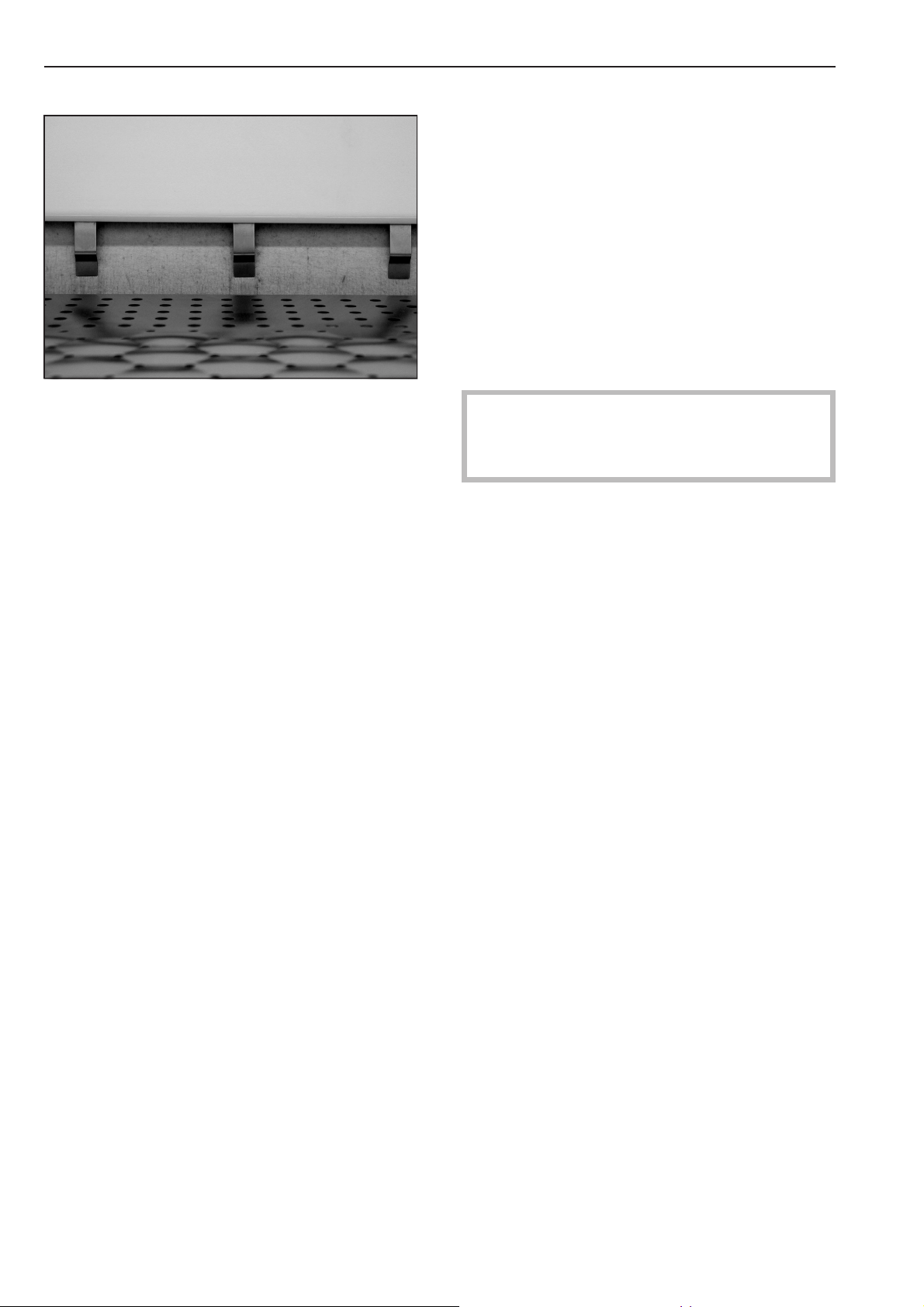
Levelling and securing the ironer
Use a spirit level and the adjustable feet to
align the machine.
Tighten the counter nuts on each foot up
against the machine columns.
The ironer should be secured to the floor
using the bolts and washers supplied in the
accessories pack.
Drillings for the bolts can be made through
the holes in the securing brackets (see the
Installation diagram).
The machine must be transported on its
wooden base to its installation site. Only then
should it be taken off the wooden base.
Points for lifting gear such as straps and
hooks are located underneath both side
frames on the columns near the adjustable
feet.
When setting the machine up leave at least
350 mm space at either side of the machine
so that the side panels are accessible.
Fitting the four adjustable feet
Tension release at trough drive housing
1 2
3 4
Loosen all 4 screws on the inside of the right
side column to release any tension between
the trough drive housing and the side
column. Then tighten all 4 screws again.
Remove the counter nut from each foot and
fit the securing bracket in place. Then refit
the nut and screw each foot into the
machine columns.
M.-Nr. 07 185 753 23
Page 24

Notes for the installer
Fitting the finger guard
BB
AA
First slot the lugs on the finger guard into the
slits A in the cover, and then secure the
finger guard to the underside of the feed-in
belt using 4 or 5 screws B.
Fitting the laundry shelf
Attaching the out-tabling
C
AB
Loosen screws A in both side columns and
completely remove screws B. Swing the
out-tabling into the horizontal position and fit
screws B on both sides into C. Then tighten
all the screws.
Remove the two screws on the left and right
hand side of the laundry shelf. Set the shelf
up horizontally.
A
B
The lower rivet nuts A and B in the side
columns are used for securing it in position.
After setting up and connecting the
,
machine ensure that all removable outer
panels are correctly fitted back into
position.
24 M.-Nr. 07 185 753
Page 25

Electrical connection
The electrical connection may only be
carried out by a suitably qualified technician
in accordance with local and national safety
regulations (BS 7671 in the UK).
The electrical components of this machine
comply with IEC 335-1 and IEC 335-2-44.
The machine is supplied ex-works for
connection to a ~ 3N 50/60 Hz (gas heated
versions 50 Hz) supply. See data plate for
details.
Connection should be made in
accordance with the wiring diagram, the
installation diagram and the installation
instructions to a suitable isolator, with an
on-off switch which is easily accessible for
servicing. It is important to follow all of
these carefully to ensure the machine is
connected correctly.
Notes for the installer
Factory default position for switching
mechanism. The switches are not engaged.
The wiring diagram and connection box are
located in the right hand side column. The
mains cable terminals are located in the
control box.
WARNING
THIS APPLIANCE MUST BE EARTHED
After connecting the machine
If the phase connection is incorrect the
heater plate will move into the service
position when the machine is switched on.
The "Service position" indicator light comes
on.
Disconnect the machine from the mains and
change two phases over.
Switch on at the mains again.
The "Service position" indicator light comes
on.
Turn the hand wheel in a clockwise direction
until the "Service position" indicator light
goes out. The switching mechanism is now
correctly set up and the machine can be
switched on with the "On" I button.
If the phase connection is correct the
switching mechansim will move
anti-clockwise and stop at switch 1.
If the phase connection is incorrect the
switching mechansim will move clockwise
and stop at switches 1 and 2.
M.-Nr. 07 185 753 25
Page 26

Notes for the installer
Exhaust ducting for vapour
extraction
Refer to the "Calculation of air outlet, air inlet
and ventilation cross sections" booklet.
The exhaust ducting to be installed on site,
must not be directed into any chimney which
is used by gas, solid fuel or oil fired
appliances. It must also be kept separate
from any exhaust system leading from a
tumble dryer.
The warm, moist exhaust air should be
discharged to the outside air by the shortest
route possible.
To ensure optimum flow, the ducting should
be laid with as few bends as possible and all
connections and joins should be airtight.
The connection point for the exhaust ducting
is located at the rear of the right hand
column.
To prevent the build-up of condensation in
an upward sloping exhaust ducting, a 3-5
mm ø condensate trap should be fitted at
the lowest point.
The ducting must have an internal diameter
of 70 mm.
Ensure that there is sufficient ventilation in
the room where the ironer is installed.
If the exhaust is ducted into the outside air,
the end of the duct should be protected
against bad weather conditions.
An exhaust system ducted into the open air
must be situated in such a way that it does
not cause a nuisance.
The on-site ducting system and the exit point
to the outside must be checked on a regular
basis for a build-up of fluff and cleaned if
required.
26 M.-Nr. 07 185 753
Page 27

Gas connection
Notes for the installer
Gas connection work must be carried out by
an authorised fitter in accordance with local
and national safety regulations including gas
regulations, building regulations and fire
regulations. This must be a Gas Safe
registered technician in the UK.
The installation instructions and the
installation diagram supplied with the
machine must be followed to ensure
correct gas connection.
The gas group to which the machine has
been set at the factory is given on the Gas
Data label on the rear of the machine.
If the machine is to be converted for a
different gas group, or to liquid gas, a
conversion kit is required. This is available to
order from the Spare Parts Department.
When ordering please quote the model and
serial number of the machine, as well as the
gas type, group and connection pressure in
the country of installation.
Please follow the installation instructions for
gas heated machines carefully. To ensure
safety any conversion work must only be
carried out by an authorised technician, e.g.
Gas Safe registered in the UK.
Do not attempt to repair gas heated
,
appliances yourself! Repairs must only be
carried out by an authorised technician to
ensure safety. In the event of a fault
please contact the Miele Service
Department.
Exhaust ducting
The ducting should be installed in
accordance with the installation diagram
and the installation instructions supplied with
the machine.
The exhaust ducting stub C 120 mm is
located at the rear of the machine next to the
right hand column.
Ensure that there is sufficient
,
ventilation in the room where the ironer is
installed.
On first commissioning there can be air in
the inlet pipe, with no ignition taking place in
the first safety period.
If this is the case the "Ignition fault" indicator
light will come on and the "Ignition fault" yx
reset button needs to be pressed. This may
need to be repeated several times to bleed
the air out of the system and get the flame
ignited.
If there is no sign of a flame during the
safety period the valve will shut and the
ignition will be switched off (malfunction
with locking). The "Ignition fault" indicator
light will come on. To deactivate the lock
press the "Ignition fault" yx reset button.
,
After setting up and connecting the
machine successfully ensure that all
removable outer panels are correctly fitted
back into position.
M.-Nr. 07 185 753 27
Page 28

Guarantee
Please contact your Miele Sales Office for
details concerning guarantee terms and
conditions. See the back cover for contact
details.
28 M.-Nr. 07 185 753
Page 29

M.-Nr. 07 185 753 29
Page 30

Alteration rights reserved/1012
M.-Nr. 07 185 753 / 00
 Loading...