

Miele PLW 8615 Installation diagram
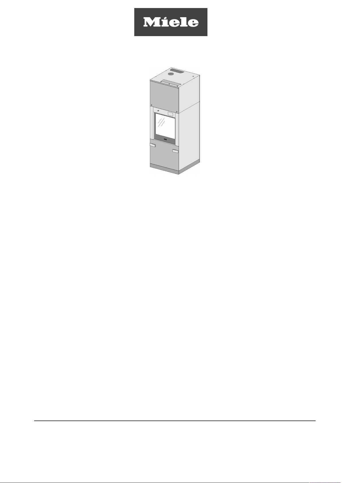
Installation plan
PLW 8615
It is essential to read the operating instructions
as well as the service documentation before the
machine is installed or used for the first time.
en - US, CA
M.-Nr. 11 426 690

Installation notes
Please read and observe the installation plan, operating instructions, programming manual and the service documents
regarding installation and setting up of this machine.
Purpose of the
installation plan
Heating
Installation
of several
machines
The installation plan provides you with information on the technical
data as well as the site conditions required for installing the machine.
This machine must be installed by a suitably qualified person with the
appropriate electrical and plumbing qualifications in accordance with
the installation instructions supplied. This machine must be installed
in accordance with all applicable standards and guidelines, including
legal requirements and health and safety regulations. The machine
must be commissioned and operatives trained in its use by Miele Service or by an approved Miele Service Partner only.
The machine type is available in two different types of heating:
- Electric (EL)
- Steam electric (D / EL)
This installation plan describes all the connection options. Depending
on the machine type and equipment variant individual connection options can be omitted.
Several machines can be installed in a row. A gap of 3/16" (5 mm) is
required between two machines. A gap of 1/8" (3 mm) is required between a machine and a partition wall.
TC (MAV) installation
Mounting the top
Cover
The gaps must be sealed with suitable flexible sealant after installation on site.
The drip trays of the individual machines can be connected together.
Alternatively, a continuous drip tray can also be installed in the toekick.
To enable the top-box panelling TC (MAV) to be placed pre-assembled on the machine, a clear height of at least 8' 7" (2.62 m) is required. If the room height is less than this, the TC (MAV) must first be
dismantled and the individual parts reassembled above the machine
and riveted again.
Mount the cover provided for this purpose on the device waterproof
hose feedthroughs. This will prevent the ingress of water into the machine when control valves or hose fittings are leaking.
Mount a front panel above the machine on site with a lockable access
panel. The utility connections are accessed from the loading / unclean side.
2 PLW 8615

Installation notes
Electrical connection
Connection to the electrical supply must be carried out in accordance
with local and national safety regulations. The power cord must be
protected from the risk of thermal damage.
The power cord should have a length of 9' 10" (3 m) on site, starting
from above the intended position of the machine.
The top edge of the top-box panelling is at a height of 8' 2" (2495
mm).
The machine's electrical connection is established from above. Establish the connection with the machine. This makes it easier to per
form safety inspections during maintenance or repair work. Route the
power cord so that it does not rest on the wash chamber.
Electrical phase order must be connected in the correct sequence
(clockwise electromagnetic field).
Do not allow the power cord to rest on the hot wash chamber!
The power cord may overheat and pose a safety hazard (avoid use
of fire). Secure all cords, including test cords, so that they cannot
rest on or directly above the wash chamber.
Grounding
Mobile plinth
For added safety, the machine should be protected with a residual
current device with a trip current of 30 mAmps. Grounding should be
carried out if required. The screw connection point for grounding (size
M8) is located at the back of the machine. Grounding must be carried
out before the machine is commissioned.
The single-door appliance can be installed on a mobile plinth. This
makes the rear of the appliance accessible for maintenance and repairs, even when it is installed in a row or against a wall. The screw
for adjusting the height of the mobile plinth is size M10 (width across
flats 0.669" (17mm)).
Mount the cover provided for this purpose on the device waterproof
hose feedthroughs. This will prevent the ingress of water into the unit
when shut off valves or hose fittings are leaking.
PLW 8615 3

Installation notes
Instructions for
routing the utility
connections
Supply connections
Plan the central control valves for the water-, steam- and compressed air connections so they are easily accessible. Only use
suitable control valves.
The lines for high-pressure steam and condensate require their own
control valves. They require a dirt trap and condensate trap in the
supply line for high-pressure steam. On site, check and install a non-
return valve for the condensate line if necessary.
For the standard installation, route the supply lines vertically from the
ceiling. The on-site connections must end at a height of 110
1/4" (2800 mm) above the finished floor level. Secure the lines once
they have been routed.
The cold water connection, hot water connection and the deionised
water supply as well as the connections for high-pressure steam,
condensate and compressed air should be routed from the ceiling to
ensure easy connection.
To connect the machine to the on-site connections, allow the hoses
to be pulled out of the TC (MAV):
- Steam 11 13/16" (300 mm)
- Water 35 7/16" (900 mm)
- Compressed air 35 7/16" (900 mm)
Water line connection
The connections have a 3/4" hose thread.
Steam line connection
Should be 1/2" male pipe thread
Compressed air connection
The machine has a compressed air connection for industrial compressed air. Industrial compressed air must be available to control
the door.
- The industrial compressed air requires an on-site coupling socket
for a Lumit 1/2" female quick-release fastener (e.g. type KKA
6S-04M from SMC).
4 PLW 8615

Installation notes
Installing a steam
condenser
If you connect the vent to an air conditioning system, a steam
condenser must be installed. If the machine is vented outside, you
do not need a steam condenser.
Observe the following when installing the steam condenser:
- The cooling circuit connections (feed and return lines) must be
routed from the ceiling.
- Install the main switches and central control valves so they are eas-
ily accessible.
- In the case of a machine with steam heating, install a non-return
valve directly downstream of the machine's condensate trap. This
prevents surges when the machine is turned on.
- Route the feed and return lines for the cooling circuit vertically
from the ceiling. The cooling circuit feed line and cooling circuit return line are connected to the nozzles on the steam condenser. To
do this, you will require a hose with an internal diameter of
9/16" (14 mm) and a nominal pressure of 116 psi (800 kPa)..
- Only use the intended conversion kits (UBS) containing pressure
hoses for the supply line and drain.
- Allow the connection hoses to hang down from the ceiling to a
length of approximately 4' 11" (1500 mm).
- Align the line sections correctly and fasten them securely.
- The ends of the cooling circuit feed and return lines should terminate within the installation area of the machine using hose nozzle.
- If there is no cooling circuit, connect the steam condenser to a cold
water connection.
- If a steam condenser with heat recovery is used, only DI water with
a maximum temperature of 68°F (20°C) may flow into the system.
PLW 8615 5

Installation notes
Drain connection
– machines with
drain pump (AP)
Observe the following instructions when connecting a drain with a
drain pump:
- The drain manifold (at least DN100; minimum diameter 4") can be
installed:
- under the floor
- to the ceiling
- Install and odor trap on site.
- Observe the maximum delivery head for the drain pump (see Technical data).
- If the machine is drained vertically towards to the ceiling, it is advisable to use pipelines instead of hoses. If necessary, DN25 to
DN40 (minimum diameter 1" to 1 9/16") pipes can be used. High
temperatures, pressures and mechanical loads from the pump
place excessive strain on the hose.
- Install the waste water line for connecting the drain hose next to the
machine.
- Hose feed-throughs in the side walls of the casing are not possible
for structural reasons.
Vent connection
Connection module – fan control
- If you are installing several machines in a row, you can create a toekick drip tray specifically for your requirements. You can place the
drain hoses in this tray.
Ventilation to atmosphere must be fan assisted. Dry contacts are
available to alert the fan controls to start the fan. The permissible flow
rates can be found under Technical data at the end of this manual.
Provide an air intake of 8,829 ft³/h (250 m³/h) for each machine on the
unclean side to replace extracted air. Connect the machine to the
ventilation or air-conditioning system. If necessary, connect a steam
condenser upstream. Install the ducting with a slope in the direction
of the extract air flow. This prevents any condensate from flowing
back into the machine. Drain the system at the lowest point.
Install separate ducting for each machine. Ducting for several machines must not be combined!
9 dry contacts are available on the machine for the connection. The
connections are located on the unclean side in the top-box panelling.
The contacts can support a maximum load of
200–240V / 1A / 50–60Hz.
When assigning the dry contacts, it is not permitted to have a
standard voltage and, for example, an extra-low voltage next to
each other.
Maintain a sufficient distance between contacts with incompatible
voltages.
6 PLW 8615
 Loading...