

Page 1

Operating Instruction
LABORATORY GLASSWARE
WASHER
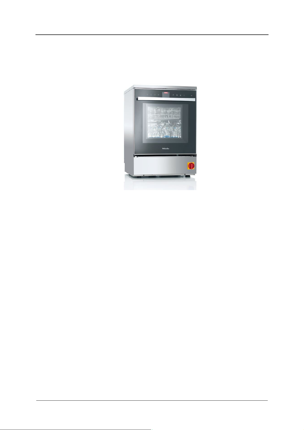
PLW 8505
To avoid the risk of accidents or damage to the
machine, it is essential to read these instructions
before it is installed and used for the first time.
en – CA, US
Page 2
CONTENT
Content
1.GENERAL RULES ............................................................................................................................ 5
1.1
Limits of manufacturer’s liability .............................................................................................. 5
1.2
Manual validity, contents and conservation ............................................................................ 5
2.PRODUCT INFORMATION .............................................................................................................. 6
2.1
Intended use, improper use .................................................................................................... 7
2.2
Safety instructions ................................................................................................................... 8
Correct application .............................................................................................................. 8
Risk of injury ........................................................................................................................ 8
Quality assurance ................................................................................................................ 9
Safety with children ........................................................................................................... 10
Using accessories ............................................................................................................. 11
Disposing of your old machine .......................................................................................... 11
Safety signal used ............................................................................................................. 11
2.3
Recommendations for proper operation ............................................................................... 12
Training .............................................................................................................................. 13
User profiles ...................................................................................................................... 13
3.INSTALLATION............................................................................................................................... 14
3.1
Water connection .................................................................................................................. 14
Inlet water quality .............................................................................................................. 14
Information......................................................................................................................... 15
3.2
Electrical connection ............................................................................................................. 16
3.3
Adding and dispensing cleaning agents ............................................................................... 17
Presence sensor of cleaning agent ................................................................................... 17
3.4
Replacement or refill of cleaning agent ................................................................................. 17
3.5
Warning ................................................................................................................................. 18
3.6
Connecting the drain hose .................................................................................................... 19
Drain cooling ...................................................................................................................... 20
3.7
Ambient ventilation requirements .......................................................................................... 20
4.CHECKS PRIOR TO START-UP .................................................................................................... 21
4.1
Introduction ........................................................................................................................... 21
4.2
Checks of safety systems ..................................................................................................... 21
4.3
General controls .................................................................................................................... 21
5.USING THE MACHINE ................................................................................................................... 22
5.1
Checking consumption ......................................................................................................... 22
5.2
Opening and closing the door ............................................................................................... 22
Opening the door using the emergency release device ................................................... 23
5.3
Switching on and off .............................................................................................................. 23
REV.0.04_COD.610078_A4 Page 2
Page 3

CONTENT
5.4
Preparation ............................................................................................................................ 24
6.CONTROL PANEL AND SYMBOLS USED .................................................................................... 25
6.1
Buttons .................................................................................................................................. 25
BUZZER ............................................................................................................................. 26
6.2
Display ................................................................................................................................... 26
7.PROGRAMS ................................................................................................................................... 29
7.1
Program blocks ..................................................................................................................... 29
7.2
Program chart ........................................................................................................................ 30
7.3
Start the program .................................................................................................................. 33
8.MACHINE STATUS ........................................................................................................................ 34
8.1
Ready for operation ............................................................................................................... 34
8.2
Program status ...................................................................................................................... 34
8.3
Power failure .......................................................................................................................... 34
8.4
Reset procedure .................................................................................................................... 35
9.MENU ............................................................................................................................................. 36
9.1
Accessing the menu .............................................................................................................. 36
9.2
Entering password ................................................................................................................. 37
9.3
Buzzer volume setting ........................................................................................................... 37
9.4
Date and time setting ............................................................................................................ 38
9.5
Selecting a language ............................................................................................................. 38
9.6
Changing user name ............................................................................................................. 39
9.7
Parameter overview ............................................................................................................... 40
10.CLOCK ...................................................................................................................................... 41
11.HISTORICAL DATA ................................................................................................................... 41
12.ALARMS AND EVENTS LIST ..................................................................................................... 42
12.1Description of alarm messages ............................................................................................. 42
12.2List of alarm messages .......................................................................................................... 42
12.3List of warning messages ...................................................................................................... 43
13.USB PORT ................................................................................................................................. 43
14.MAINTENANCE ......................................................................................................................... 44
14.1General recommendations on maintenance ......................................................................... 44
Machine status .............................................................................................................. 44
14.2Maintenance request ............................................................................................................. 44
14.3Routine maintenance ............................................................................................................. 44
14.4Table of routine maintenance tasks ...................................................................................... 45
14.5Special maintenance ............................................................................................................. 50
Table of special maintenance tasks .............................................................................. 50
15.PROBLEMS – CAUSES – REMEDY .......................................................................................... 51
15.1Introduction ........................................................................................................................... 51
15.2Problems (P.) – Causes (C.) – Remedy (R.) ........................................................................... 51
REV.0.04 _COD.610078_A4 Page 3
Page 4

CONTENT
16. TECHNICAL DATA .................................................................................................................... 53
17. DISPOSING OF YOUR OLD MACHINE .................................................................................... 55
REV.0.04_COD.610078_A4 Page 4
Page 5

1. GENERAL RULES
1.1 Limits of manufacturer’s liability
The manufacturer shall not be held liable for failures or problems which arise due to
tampering and/or incorrect applications and/or improper use of the machine.
The user must comply with all instructions set forth in the user's manual:
Always work within the allowable limits for the use of the machine
Always carry out constant and diligent maintenance
Allow use of the machine by persons with proper skills and abilities for their role and
purpose who have been properly trained and instructed
Use only manufacturer original spare parts
Any modifications, adaptation or the like which may be made to machines which are
subsequently placed on the market do not oblige the manufacturer to intervene on previously
supplied machines, nor to consider the machine and the related user's manual lacking and
inadequate.
The installation, maintenance and operating instructions given in the following pages have
been prepared to ensure the long life and outstanding performance of the appliance.
The instructions in this manual do not replace but rather are in addition to employer
requirements to adhere to current legislation on standards of prevention and safety.
GENERAL RULES
1.2 Manual validity, contents and conservation
It is important to keep this instruction manual with the machine for future reference.
If the machine is sold or transferred, the manual must be handed over to the new owners or
user in order for them to become acquainted with its functioning and the relative warnings.
Read the warnings carefully before installing and using the machine.
REV.0.04 _COD.610078_A4 Page 5
Page 6
PRODUCT INFORMATION
2. PRODUCT INFORMATION
Before starting work, the user must be completely familiar with the functions and proper
operation of the machine. The user must know the precise function of all command and
control devices of the machine.
PLW 8505
REV.0.04_COD.610078_A4 Page 6
Page 7
2.1 Intended use, improper use
This laboratory glassware washer is designed for washing laboratory glassware and
laboratory utensils with water based media. It is designed for use in laboratories in schools,
colleges and universities.
The process includes cleaning, rinsing and drying.
Due to the wide variety of laboratory glassware and laboratory utensils on the market, it may
be necessary in some cases to establish whether it is suitable for cleaning in a laboratory
glassware washer.
This will depend on its use and the type of soiling present. Please also observe information
provided by the manufacturer of the laboratory glassware and laboratory utensils.
Laboratory glassware and laboratory utensils suitable for cleaning include, for example:
Vessels such as test tubes, beakers, flasks, cylinders, etc.
Measuring vessels such as measuring cylinders, volumetric flasks, etc.
Dishes such as petri dishes, watch glasses, etc.
Small items such as lids, spatulas, magnetic stirring rods, stoppers, etc.
Other items such as funnels
Laboratory glassware and laboratory utensils for cleaning are referred to as the wash load if
they are not more specifically defined.
Processing conditions must be suitable for the wash load and for the type of soiling.
Cleaning agents must be suitable for the type of soiling and for methods of analysis being
used.
The use of a suitable carrier (mobile unit, basket, module, insert, etc.) is important to ensure
adequate processing of the load.
PRODUCT INFORMATION
WARNING
Inappropriate use can, however, lead to personal injury and material
damage.
Miele cannot be held liable for damage caused by improper or incorrect
use or operation of the machine.
If the appliance is used in a manner not specified by the manufacturer,
protection of the appliance may be compromised.
REV.0.04 _COD.610078_A4 Page 7
Page 8
PRODUCT INFORMATION
2.2 Safety instructions
This machine complies with all statutory safety requirements. Inappropriate use can,
however, lead to personal injury and material damage.
Read these instructions carefully before using it for the first time to avoid the risk of
accidents and damage to the machine.
Keep these instructions in a safe place where they are accessible to users at all times.
Correct application
This lab washer is designed for use with the applications described in these operating
instructions only. Alterations or conversions to the machine, or using it for purposes other
than those for which it was designed, are not permitted and could be dangerous. This lab
washer must only be used for cleaning laboratory glassware and utensils if the
manufacturer has stated that they are suitable for machine cleaning.
Manufacturer's cleaning and maintenance instructions must also be observed.
Miele cannot be held liable for damage caused by improper or incorrect use or operation
of the machine.
This machine is intended for indoor use only.
Risk of injury
Please pay attention to the following notes to avoid injury
Do not install the machine in an area where there is any risk of explosion or of freezing
conditions.
In order to reduce the risk of water damage, the area around the machine should be
limited to furniture and fittings that are designed for use in commercial environments.
Some metal parts pose a risk of injury/being cut. Wear cut-resistant protective gloves
when transporting and setting up the machine.
If the machine is built under, it must only be installed under a continuous countertop
which is firmly secured to adjacent units to improve stability.
The electrical safety of this machine can only be guaranteed when correctly grounded. It
is essential that this standard safety requirement is met. If in any doubt, please have the
on-site wiring system tested by a qualified electrician. Miele cannot be held liable for the
consequences of an inadequate grounding system (e.g., electric shock).
A damaged or leaking machine could be dangerous and compromise your safety.
Disconnect the machine from the power supply immediately and call the Miele Service
Department or an authorized and trained service technician.
Personnel operating the machine should be trained regularly. Untrained personnel should
not be allowed to use the machine.
Only use cleaning agents which have been approved by their manufacturer for use in the
application you are using. The cleaning agent manufacturer is responsible for any
negative influences on the material the load is made from and for any damage they may
cause to the machine.
Take care when handling cleaning agents. These may contain irritant, corrosive or toxic
ingredients.
Please observe the cleaning agent manufacturer's safety instructions and safety data
sheets. Wear protective gloves and goggles.
The machine is designed for operation with water and recommended additive cleaning
agents only.
REV.0.04_COD.610078_A4 Page 8
Page 9

Organic solvents and flammable liquid agents must not be used in the machine. This
could cause an explosion, damage rubber or plastic components in the machine and
cause liquids to leak out of it.
The water in the cabinet must not be used as drinking water.
Do not lift the machine by protruding parts such as the control panel or the opened
service flap as these could be damaged or torn off.
Do not sit or lean on the opened door. This could cause the machine to tip up and be
damaged or cause an injury.
Be careful when sorting items with sharp pointed ends and positioning them in the
machine that you do not hurt yourself or create a danger for others.
Broken glass can result in serious injury when loading or unloading. Broken glass items
must not be processed in the machine.
When using this machine in the higher temperature ranges, be especially careful not to
scald or burn yourself or come into contact with irritant substances when opening the
door.
Should personnel accidentally come into contact with toxic vapors or cleaning agents,
follow the emergency instructions given in the manufacturer's safety data sheets.
Mobile units, baskets, modules, inserts and the load must be allowed to cool down
before they are unloaded. Any water remaining in containers could still be very hot.
Empty them into the wash cabinet before taking them out.
Never clean the machine or near vicinity with a water hose or a pressure washer.
The machine must be disconnected from the power supply before any maintenance or
repair work is carried out.
Quality assurance
The following points should be observed to assist in maintaining quality standards
when processing laboratory glassware and utensils to avoid damage to the loads being
cleaned.
If it is necessary to interrupt a program, this may only be done by the designated user.
The standard of cleaning should be routinely confirmed by the user.
Make sure items being washed are suitable for machine cleaning and are in good
condition. Plastic items must be thermally stable. Nickel-plated items and aluminium
items can be machine processed using special procedures only.
Items containing iron and soiling containing residual rust must not be placed in the
cabinet.
Cleaning agents can, in certain circumstances, cause damage to the machine. Always
follow the recommendations of the cleaning agent manufacturer.
In case of damage or doubt about compatibility, please contact Miele.
Do not use bleach in the washer.
Abrasive substances must not be placed in the machine as they could cause damage to
the mechanical components of the water circuit. Any residues of abrasive substances on
items to be washed must be removed without trace before cleaning in the machine.
Pre-treatments with cleaning agents can create foam, as can certain types of soiling.
Foam can have an adverse effect on the cleaning result.
Foam can cause leakage and damage to the washer.Therefore do not use cleaning
agents that foam and set up the processes such that no foaming occurs.
PRODUCT INFORMATION
REV.0.04 _COD.610078_A4 Page 9
Page 10

PRODUCT INFORMATION
Where a cleaning agent is recommended on technical application grounds (e.g., a
cleaning agent), this does not imply that the manufacturer of the machine accepts liability
for the effect of the chemical on the items being cleaned.
Please be aware that changes in formulation, storage conditions, etc., which may not be
advertised by the chemical manufacturer can have a negative effect on the cleaning
result.
When using a cleaning agent it is essential that the manufacturer's instructions are
followed. The cleaning agent must only be used for the application it is designed for and
in the situation specified to avoid material damage and such dangers as a severe
explosive chemical reaction (e.g., an explosive oxyhydrogen gas reaction).
Always follow the relevant manufacturer's instructions on storage and disposal of
cleaning agents.
In critical applications where very stringent requirements have to be met, it is strongly
recommended that all the relevant factors for the process, such as cleaning agents,
water quality, etc., are discussed with the Miele Application Technology specialists.
The mobile units, baskets, modules and inserts that hold the load must be used only as
intended.
Hollow items must be thoroughly cleaned, internally and externally.
Secure small and light items with cover nets or place in a mesh tray for small items, so
that they do not block the spray arms.
Empty any containers or utensils before loading them.
The amount of residual solvents and acids on items going into the cabinet should be
minimal.
There should be no more than a trace of any solvents with a flash point of below
70°F (21 °C).
Ensure that solutions or steam containing chlorides or hydrochloric acid do not come into
contact with the wash cabinet, accessories and stainless-steel outer casing of the
machine in order to avoid any damage through corrosion
After any plumbing work the water pipework to the machine will need to be vented. If this
is not done, components can be damaged.
The gaps between a built-in machine and adjacent cabinetry must not be filled, e.g., with
silicone sealant as this could compromise the ventilation to the circulation pump.
Follow the installation instructions in the operating and installation instructions.
Safety with children
Children must be supervised in the vicinity of the machine. Do not allow children to play
with the machine. They could get locked inside it.
Children must not use the machine.
Keep children away from cleaning agents. These can cause burning in the mouth, nose
and throat if swallowed, or inhibit breathing. Keep children away from the machine when
the door is open. There could still be residual cleaning agent in the cabinet. Observe the
safety data sheets for the cleaning agent and seek medical advice immediately if a child
has swallowed cleaning agent or got it in the eyes.
REV.0.04_COD.610078_A4 Page 10
Page 11
Using accessories
Only designated accessories should be connected to this machine. They must be
suitable for the application they are required for. Consult Miele for details on the type of
accessories that can be used.
Only use designated mobile units, baskets, modules and inserts with this lab washer.
Using mobile units, baskets, modules and inserts made by other manufacturers, or
making modifications to the original accessories can cause unsatisfactory cleaning
results, for which Miele cannot be held liable. Any resultant damage would not be
covered by the guarantee.
Disposing of your old machine
For environmental and safety reasons ensure the machine is completely drained of any
residual water, chemical residues and cleaning agent. Observe safety regulations and
wear safety goggles and gloves.
Make the door lock inoperable so that children cannot accidentally shut themselves in.
Then make appropriate arrangements for its safe disposal.
Safety signal used
To inform personnel operating on the machines of obligations of behavior and residual risks,
adequate safety signals (as set forth by 92/58 EEC) are applied to the machine and near the
workplace.
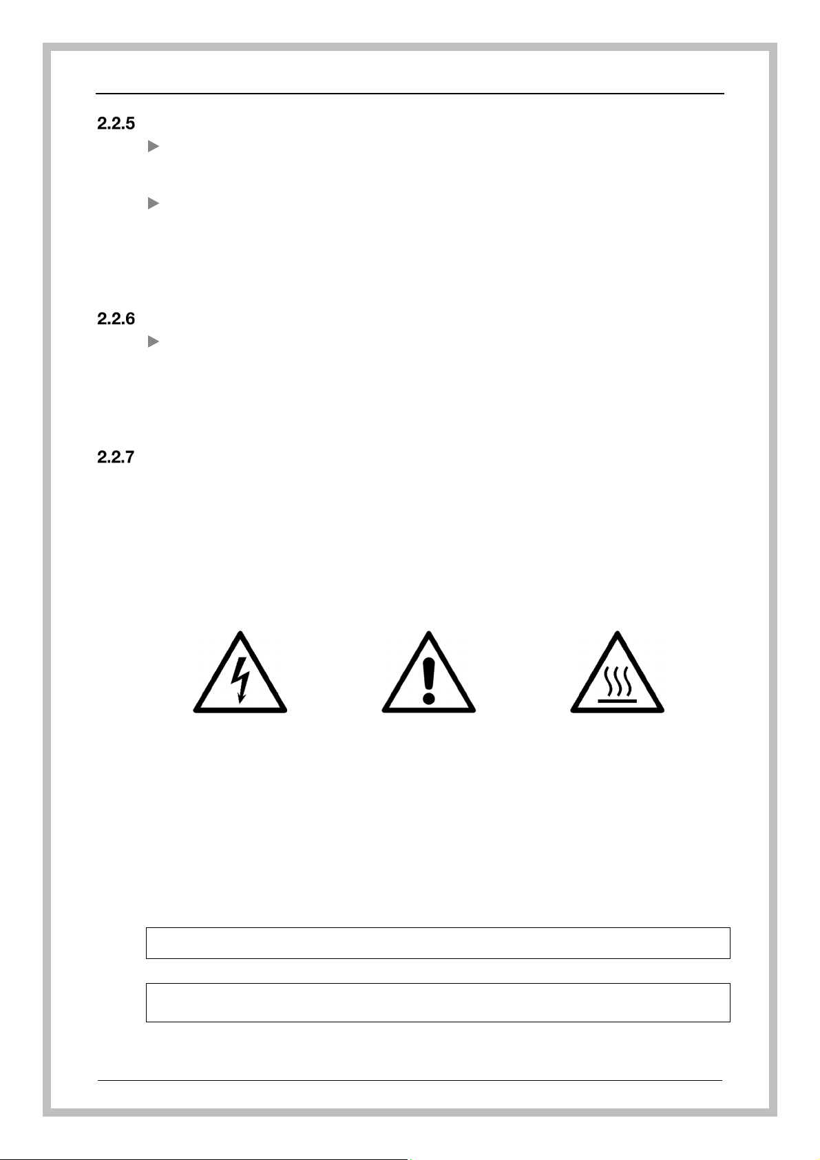
GENERIC SAFETY SIGNALS:
In particular, labels with signals of obligation, prohibition and danger contained in this manual
and pertinent to this machine and most commonly used are:
PRODUCT INFORMATION
Warning
Danger of electrical
shock!
PERSONAL PROTECTIVE EQUIPMENT:
The evaluation of risks for the health and safety of users carried out in the workplace and on any
equipment used, as well as the evaluation of residual risks as indicated, allow the employer to evaluate
the need to adopt the individual protection gear which is most suitable and appropriate to be provided
to users.
Considering the type of machine, it is felt that the individual protection gear should be provided to staff.
Observe the operating
Warning
instructions
Warning
Hot Surface
SAVE THESE INSTRUCTIONS
Miele cannot be held liable for damage caused by non-compliance with these safety
instructions.
REV.0.04 _COD.610078_A4 Page 11
Page 12

PRODUCT INFORMATION
2.3 Recommendations for proper operation
The machine may never be left unattended while in operation.
When the machine is running do not interrupt the cycle.
Use recommended detergents and cleaning agents only. The use of other products
may damage the machine.
Do not introduce any items with substances that must not be discharged in sewage
system (in accordance with local legislation).
Recommending cleaning agents does not make the manufacturer responsible for any
damage to the materials and cleaned items.
Check that type of cleaning agent is suitable for the specific washing program used.
Follow the manufacturer's instructions when using cleaning agents and use them for
the foreseen use only.
Follow the manufacturer’s instructions and local and national requirements and
guidelines, on how to clean their items by machine.
The machine was designed for use with water and cleaning agents.
Do not use organic or other types of solvents as this may result in the risk of explosion
or the rapid deterioration of certain machine parts.
Acids, particularly hydrochloric acid, can damage steel. Contact should be avoided.
Use original accessories only.
Never use powder detergents.
Never use foaming detergent.
Accessories which are not approved by the manufacturer may compromise the results
achieved as well as user safety.
Never use cleaning agents based on chlorides and hypochlorites (bleaches, sodium
hypochlorite, hydrochloric acid and so on). These kinds of cleaning agents irreparably
damage the machine and jeopardize the integrity of materials and objects treated.
The user must carry out a general check-up and clean the appliance regularly as
indicated in the maintenance chapter.
Connection to the water supply should be easily accessible so that the water supply
can be turned off when necessary.
The manufacturer declines all responsibility for personal injury or material damage resulting
from non-compliance with the above rules.
REV.0.04_COD.610078_A4 Page 12
Page 13

Training
Instructions for use of the machine will be provided by Miele Service or an authorized
representative during machine commissioning.
It will be the duty of the employer to check that the degree of staff training is suitable for
assigned duties.
User profiles
Depending on the difficulty of certain installation operations and of the operation and
maintenance of the system, user profiles are identified as follows:
SERVICE Installation and repair technican.
ADMIN Responsible authority for the machine in the workplace:
USER Machine user:
PRODUCT INFORMATION
More advanced tasks, e.g., interrupting or canceling a program, require more
detailed knowledge about the machine cleaning of laboratory glassware and
laboratory untensils.
Alterations or adaptations of the lab washer, e.g., accessories used or on-site
conditions require additional specific knowledge of the lab washer.
We recommend only designated qualified personnel be allowed to operate
the washer.
REV.0.04 _COD.610078_A4 Page 13
Page 14
INSTALLATION
3. INSTALLATION
3.1 Water connection
Inlet water quality
The quality of the water used in all the cleaning stages is important to have good results.
The water used in each stage must be compatible with:
The material of which the machine is made.
The chemicals used in the process.
Process requirements for the various stages of the process.
In order to achieve good cleaning results, the machine needs to operate with soft water. Hard
water results in the build-up of calcium deposits on the load and in the machine.
If the mains water hardness level is more than 7 °fH (0.7 mmol/l or 4°dH), a water softening
system should be provided on site.
Note: It is the user’s responsibility to supply the machine with suitable water.
ATTENTION
Water from the wash cabinet must not be consumed.
The lab washer must be connected to the water supply in strict accordance with current local
and national water authority regulations.
The water used must be drinking-water quality. If the water supply has a high iron content
there is a danger of corrosion occurring on items being cleaned in the lab washer, as well as
the appliance itself. If the chloride content of the water exceeds 100 mg/l the risk of corrosion
to items being cleaned in the lab washer will be further increased.
In certain regions (e.g., mountainous areas) the water composition may cause precipitates to
form, requiring the use of softened water in the steam condenser.
The lab washer is supplied as standard for connection to cold water (blue coded) and hot
water up to max. 140 °F (red coded). Connect the inlet hoses to the water valves for cold and
hot water.
If there is no hot water supply available, the inlet hose coded red must also be connected to
the cold water supply.
The minimum flow pressure for cold water, hot water and for DI water connection is 14.5
psi (100 kPa).
Recommended flow pressure for cold and hot water connections is ≥ 29 PSI pressure and
for DI water connection ≥ 29 PSI pressure, to avoid excessively long water intake times.
The maximum permissible static water pressure is 116 psi (800 kPa) pressure.
If it is below 14.5 psi (100 kPa) dynamic pressure, you will need to install a pressure
increase pump. If the pressure is higher than 145 psi (1000 kPa) a pressure reducer
must be installed.
If the water pressure does not fall into the stated range, contact Miele Service or an
authorized and trained service technician for advice.
A water valve with a ¾" threaded union must be provided on site. It should be easily
accessible so that the water supply can be turned off when the machine is not in use.
REV.0.04_COD.610078_A4 Page 14
Page 15
Information
INSTALLATION
IMPORTANT
Do not overtighten the threaded unions on the hoses!
The back flow prevention system is already installed inside the machine according to
IEC61770;
If the connection of hot and cold water is not available, the two corresponding supply
pipes must be connected together;
The manufacturer declines all responsibility for damage or injury caused by improper
installation.
If you do not comply with the conditions above, the deriving damages will not
warranty.
ATTENTION
When the machine is not in operation, always close the water valves.
REV.0.04 _COD.610078_A4 Page 15
Page 16
INSTALLATION
3.2 Electrical connection
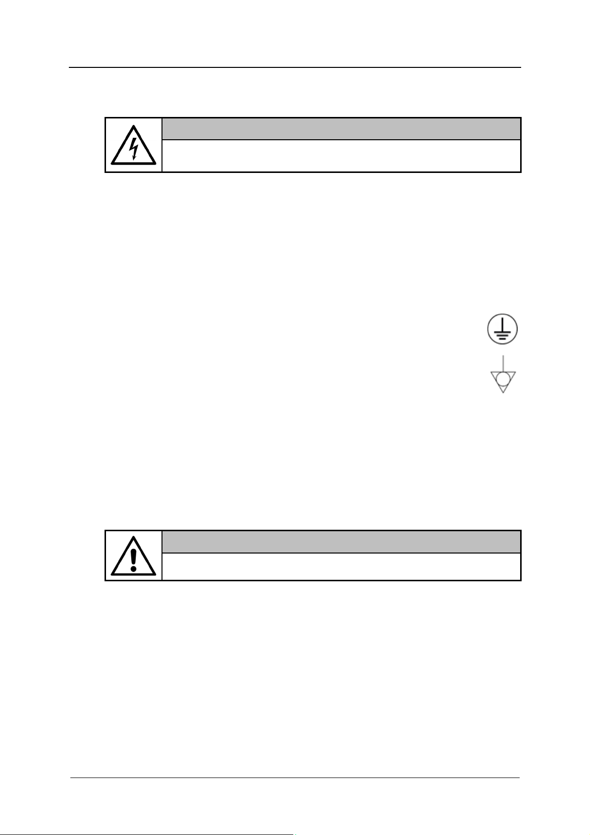
ATTENTION
Connection of the machine to the electrical to the electrical supply must be
made by qualified, skilled personnel.
Make sure that the power supply voltage reading corresponds to the voltage indicated
on the data tag
Check that the power supply voltage does not differ by more than 10% from its
nominal value.
The frequency of the power supply voltage must not differ by more than 1% of its
value.
Connection of the machine to the power supply must be provided with a ground
connection and an equipotential circuit as set forth by current standards.
Make sure that the electrical systems are efficiently grounded.
The ground conductor is to be connected to the ground terminal identified
by the standard symbol.
The machine is equipped with a terminal identified by the relative symbol for
equipotential connections between appliances (see rules for electrical
plants).
Connect the machine and the relative dedicated disconnection device (not supplied)
by using a power cable compatible with the electrical characteristics of the machine.
In case of prolonged take up of the machine it is recommended that you execute the
disconnection procedure of the electrical connection by placing the dedicated
disconnection device in "OFF" state.
The upstream electrical power line must be dimensioned and protected in accordance
with current local regulations.
ATTENTION
Please refer to the installation plan provided.
REV.0.04_COD.610078_A4 Page 16
Page 17
3.3 Adding and dispensing cleaning agents
The dosing system of cleaning agents is composed of:
1 dosing pump for detergent
1 dosing pump for neutralizing agent
Level sensor cleaning agent
Presence sensor of cleaning agent
Each dosing pump is combined with a sensor that confirms the presence of cleaning agent
inside the container. In case of product lack, the electronic control system of the machine
indicates a message in the display.
3.4 Replacement or refill of cleaning agent
To replace the cleaning agent container perform the following procedure:
Have a new container with cleaning agents ready.
Take the empty container.
Remove the siphon and place it on a chemical-resistant and easy-to-clean surface.
Insert the siphon into the new container.
Wipe up any spillages.
Place the cleaning agent container in the area for the storage of chemical substances.
Venting Dosing System by execute the Fill DOS1 program for detergent or Fill DOS2
program for neutralizer.
INSTALLATION
ATTENTION
Only use cleaning agents designed specifically for use in the machine and
follow the manufacturer's instructions on their application.
Caution when using cleaning agents. Some agents may be corrosive and
irritant. The relevant safety regulations and the cleaning agent
manufacturer's safety data sheets must be observed. Wear protective
goggles and gloves.
REV.0.04 _COD.610078_A4 Page 17
Page 18

INSTALLATION
3.5 Warning
For the maximum amount of cleaning agent which can be used per washing cycle,
follow the instructions for the cleaning agent you are using.
To ensure the efficiency of the chemical dosing system it is recommended to consider
the table of routine maintenance tasks; see the “Maintenance” chapter.
Use liquid cleaning agents only. Do not use powder detergent.
Always follow the relevant manufacturer's instructions on storage and disposal of
cleaning agents.
Check that the type of cleaning agents is suitable for the specific washing program
used.
ATTENTION
Before undertaking any sort of movement of the machine, ensure the
machine is completely drained of any residual water, chemical residues
and cleaning agent if necessary.
This procedure must be carried out, in order to prevent contact of the
cleaning agents with body parts and machine components that can be
damaged.
REV.0.04_COD.610078_A4 Page 18
Page 19

3.6 Connecting the drain hose
The drain hose connection should be checked carefully.
The machine is equipped with a drain hose with a diameter indicated on the
installation plan.
The choice of materials relating to the ventilation circuit for drainage operations must
take into account the same requirements as for piping that comes into direct contact
with drain fluids; it must be taken into consideration that these may give off harmful
(corrosive, toxic, etc.) vapors that may involve the output/input point of the duct.
CAUTION
If the drain system is clogged take great care when processing the water
and avoid contact with hands, eyes, etc., in the case of contact rinse the
parts concerned with plenty of water.
The drain hose is connected to the sewer network in the following manner:
Identify the drain pipe and relative fittings, and assemble them.
Make sure the seal gasket is installed correctly.
Identify the drain manifold and connect the hose via the union and ring nut. Tighten
the ring nut firmly.
Insert the drain hose and clamp it in place.
Insert the other end of the hose into the drain unit, installing it properly and locking it
in position.
It is necessary to follow these instructions for drain connection:
Drain hose must be connected by using a clamp.
Drain hose must not present angles or irregular curving in its course.
Drain point must be placed at the same height of the machine drain point or on the
floor.
INSTALLATION
Carefully follow these instructions as a wrong drain connection can cause the block of
machine.
The diameter of main drain must be as indicated on the installation plant.
Avoid drain pipe extension.
ATTENTION
Drainage must be done following international rules.
The manufacturer cannot be held responsible if an inaccurate if
inaccurate machine use causes pollution.
If the drain system is clogged take great care when processing the water
and avoid contact with hands, eyes, etc. In the case of contact rinse the
parts concerned with plenty of water.
When the machine is connected to an exhaust ventilation system, the
drain hose should be positioned outside the building, protected from any
animal access, and make sure that it not causes any hazard.
REV.0.04 _COD.610078_A4 Page 19
Page 20

INSTALLATION
Drain cooling
The machine is equipped by a system of drain cooling, which can be useful in order to reduce
the temperature from the standard temperature of 200° to 140°F (93° to 60°C).
3.7 Ambient ventilation requirements
During normal operation, the machine warms up itself dispersing heat and humidity.
Therefore, in order to guarantee a comfortable environment with good temperature and
humidity for the user, it is necessary to prepare an air conditioning or air circulation system
capable to balance the emissions reported in the installation plan.
Only when toxic detergents are used and/or it is expected that it is not possible to guarantee
acceptable levels of temperature and humidity in the installation environment, the air exhaust
of the equipment must be connected to a venting system.
The air that is expelled from the chamber must not be re-circulated so as to protect the user
from any undesired emissions produced by the machine or by the chemical products present
within the work area.
The machine connections are shown in detail on the
installation plan and electrical wiring diagram.
REV.0.04_COD.610078_A4 Page 20
Page 21

CHECKS PRIOR TO START-UP
4. CHECKS PRIOR TO START-UP
4.1 Introduction
The preliminary adjustments and controls are performed by a skilled technician who has been
specifically trained for this purpose.
4.2 Checks of safety systems
Indicative list of adjustments and checks of safety systems and devices to be carried out:
Check the mains supply voltage
Check the efficiency of the emergency and machine shutdown devices (circuit
breaker)
Check the efficiency of the door opening safety microswitch
Check the operation of machine controls, especially the START and STOP
commands
4.3 General controls
Indicative list of general adjustments and checks to be made:
Check proper execution of general supplies of the machine (electrical and plumbing)
Ensure that the user is trained for its use
Check that the motors installed on the machine rotate in the correct direction (only for
machines equipped with three-phase power supply motors)
REV.0.04 _COD.610078_A4 Page 21
Page 22

USING THE MACHINE
5. USING THE MACHINE
5.1 Checking consumption
Check consumption regularly by checking the fill levels in the supply containers and replace
containers in a timely manner before they are completely empty. Otherwise the dispensing
system will need repriming.
Wear appropriate individual protection gear (personal protection equipment).
Follow the instruction in the „ADDING AND DISPENSING CLEANING AGENTS”
section.
ATTENTION
Take care when handling cleaning agents. These may contain irritating,
corrosive or toxic ingredients.
Prior to use, carefully read the safety information provided by the
cleaning agent supplier and the label applied to the package.
5.2 Opening and closing the door
Pull on handle to open door.
The glass door is insulated, however it may be hot. Use caution when opening not to touch it.
ATTENTION
Keep hold of the door during opening and closing. Jerking the door open
or slamming it shut may break the glass.
Insert the basket with care into the wash chamber to avoid the risk of
breaking glass.
Before opening the door, check that the opening area is free from
obstacles.
The machine is equipped with an electric door lock in order to prevent it from being opened
when the machine is running.
REV.0.04_COD.610078_A4 Page 22
Page 23

USING THE MACHINE
Opening the door using the emergency release device
ATTENTION
The emergency release may only be used when it is no longer possible to
open the door normally, e.g., in the event of a power failure.
If the emergency release is operated during a program cycle, hot water
and cleaning agents can escape.
There is a risk of burning, scalding or chemical burns.
If a program is cancelled, the items in the lab washer must be cleaned
again.
1. An emergency release device is located above the
door, labelled accordingly.
2. Insert the tool into the emergency release opening.
3. Keep pushing the tool. In this moment the door is
unlocked and it is possible to open it.
4. To close the door, keep pushing the tool as
described above while pushing the door at the
same time.
5.3 Switching on and off
The machine is switched on and off by turning the main switch at the bottom right
REV.0.04 _COD.610078_A4 Page 23
Page 24

USING THE MACHINE
5.4 Preparation
Make sure that the items can be cleaned inside the machine and verify the
compatibility with the cleaning agents used during the cycles.
Place the items to be washed inside the machine and position them carefully on the
holder and in the rack.
Items should not overlap.
Items should be positioned so that liquids can flow out easily.
Tall or heavy items should be placed towards the middle of the basket if possible to
facilitate washing.
Make sure that nothing is blocking the arms and that they turn freely.
Place the load uniformly in the basket.
The mobile units, baskets, modules and inserts that hold the load must be used only
as intended.
Empty any containers or utensils before loading them.
Take apart any items which can be dismantled according to the manufacturer's
instructions and process the individual parts separately from each other.
Do not place items to be cleaned inside other pieces where they may be concealed.
Do not place items so close together that cleaning is hampered.
Arrange the load so that water can access all surfaces.
Only clean small items and micro components in special inserts, mesh trays with lids
or mesh inserts.
Plastic items must be thermally stable.
ATTENTION
The maximum load for each cycle is 44lbs (20 kg) (basket included).
Never use the machine without basket.
Before starting to use the machine, please make sure that all the routine checks have been
made. Verify the wash arms and their rotation.
ATTENTION
Never empty any solid waste into the machine.
This will block the drain system with pump and destroy the machine.
Noncompliance, even in part, of the rule here indicated, can cause
dangerous leakage of water from the door.
REV.0.04_COD.610078_A4 Page 24
Page 25

CONTROL PANEL AND SYMBOLS USED
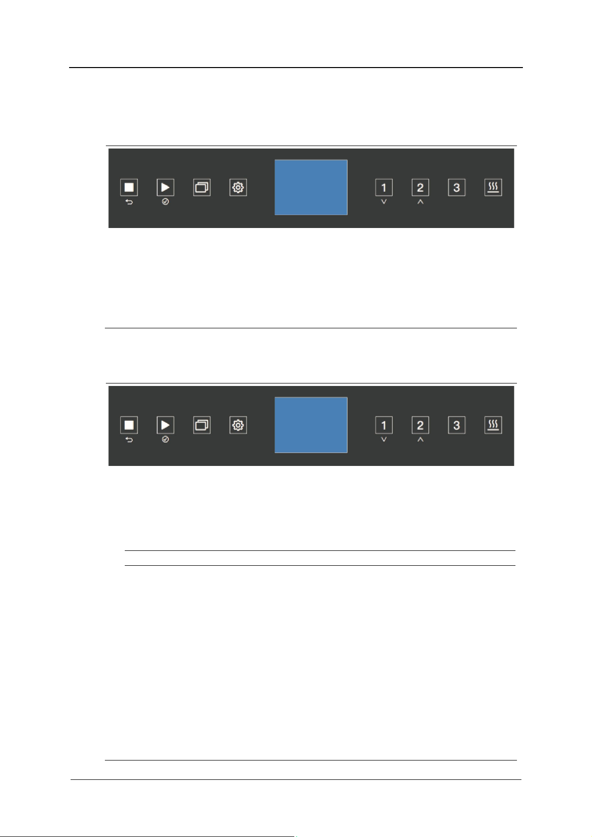
6. CONTROL PANEL AND SYMBOLS USED
The control panel with liquid crystal display is illustrated in the image.
This panel makes the machine easy to use, as it indicates the cycle phases in progress and
the temperature reached during each cycle phase; besides, it displays any error messages.
A
6.1 Buttons
The buttons of the glass display are touch-sensitive and backlit (LED). There are 8 buttons
available with the following functions:
B
C
D
Display
E
F
G
H
BUTTON DISCRIPTION
One press for interrupting a program.
The display advices the disinfection lack and the “manual
stop” message appears, the door remains locked and, if
necessary, it indicates the temperature inside the chamber.
By pressing START, the machine restarts the cycle execution
from the point, in which it had been stopped.
Two presses for canceling a program.
The machine returns to the stand-by condition and the door
is unlocked.
For canceling a process.
Starting a program.
For selecting or confirming entries in the user interface.
For accessing the list of all additional programs.
The menu incorporates all relevant functions.
During standby: Press the button for 5 seconds to access the menu.
Short program
For navigating within the display.
Standard program
For navigating within the display.
A
B
C
D
E
F
STOP
(cancel)
START
(confirm)
P+
PRG
P1
(down)
P2
(up)
G
H
REV.0.04 _COD.610078_A4 Page 25
P3
DRY
Intensive program
Drying function.
Before starting a program, it is possible to add additional drying time
or to deactivate the drying function.
The standard drying setting is 20 minutes on each program.
By pressing the button once, an additional 5 minutes is added to the
drying time, for a total drying time of 25 minutes.
By pressing the drying button twice, the drying step will be
deactivated.
Page 26

CONTROL PANEL AND SYMBOLS USED
BUZZER
The buzzer sounds each time a button is pressed and intermittently in the case of a machine
shutdown (see “MALFUNCTION” section).
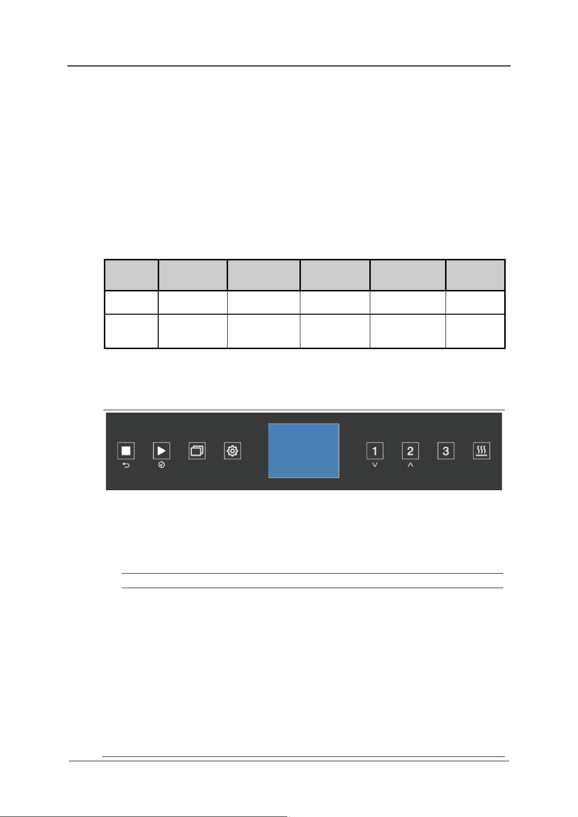
6.2 Display
1
8
2
3
4
9
5
6
7
PIC.1
PIC.1
Display the following information:
1. Date and time
2. Selected program and program position
3. Current program phase
4. Temperature in chamber (Sensor 1) with A0 value
5. Target temperature for current program phase
6. Remaining time
7. Warning message
8. Cycle counter
9. Temperature in chamber (Sensor 2) with A0 value
At the beginning, while the machine is in the stand-by status, it displays the type of program
selected, temperature, date and time.
By pressing one of the program button (P1 , P2 or P3 ), the display shows the
program associated to the key and at the left bottom the following message: "press start" or
"door open".
By pressing the P+ button, it is possible to scroll all the available programs.
REV.0.04_COD.610078_A4 Page 26
Page 27

CONTROL PANEL AND SYMBOLS USED
PIC. 2
During the cycle, by pressing the PRG button it
is possible to display the screen showing the
various machine temperatures (Pic. 2).
PIC. 3
By pressing PRG button twice a screen with
alarms and warnings is displayed (Pic. 3).
PIC. 4
In case of an error, a window appears indicating
the identification alarm code and a brief description
as shown in Pic.4.
In case of failure, which does not lead to a block (such as lack of chemical) a message is shown
at the left bottom of the screen (Pic.1 point 7) or by pressing twice the PRG button as shown
in Pic.3.
REV.0.04 _COD.610078_A4 Page 27
Page 28
CONTROL PANEL AND SYMBOLS USED
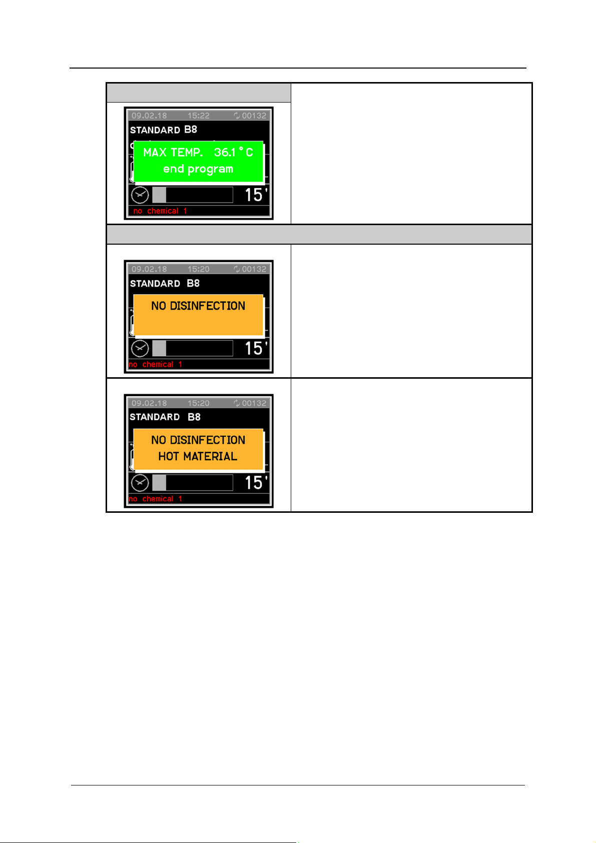
PIC. 5
At the end of the cycle, a window appears as
displayed in Pic.5.
PIC. 6
Pic.6.A
In case a cycle was interrupted, a window appears
with a message warning the disinfection lack
(Pic.6.A).
In case of cycles without desinfection, this window
appears by pressing STOP only once.
Pic.6.B
If the temperature in a cancelled program was
149°F (65°C) or lower, the message shown in Fig.
6.A is displayed.
If the temperature was above 149°F (65°C), the
message shown in Fig. 6.B is displayed.
REV.0.04_COD.610078_A4 Page 28
Page 29

7. PROGRAMS
7.1 Program blocks
Drain
For draining wash water.
Pre-wash
A pre-wash removes coarse soiling and foaming agents.
Main wash
Depending on load, cleaning generally occurs at temperatures between 113°F (45 °C)
and 149°F (65 °C) with the addition of appropriate cleaning agent.
Interim rinse
In the interim rinse stages, the cleaning agents from the previous wash blocks are
rinsed off and neutralized where necessary by the addition of appropriate neutralizing
agents.
Final rinse
To avoid deposits and corrosion on the load, demineralized (AD) water should
preferably be used, if available, for the final rinse.
Drying
PROGRAMS
REV.0.04 _COD.610078_A4 Page 29
Page 30

PROGRAMS
7.2 Program chart
Drying
Wash
Wash
Wash
Wash
Wash
Wash
Drying
2
Final
rinse
1
Final
rinse
rinse
Interim
rinse
Interim
2
rinse
Interim
2
-zation
Neutrali
4
3
DI
140°F
(60°C)
DI
1 Min
140°F
(60°C)
DI
1 Min
HW
140°F
(60°C)
DI
1 Min
DI
1 Min
140°F
(60°C)
DI
1 Min
HW
1 Min
1 Min
140°F
(60°C)
1 Min
Wash
Wash
Wash
Wash
Wash
1
-zation
Neutrali
2
Main
wash
1
Main
wash
Pre-
wash
1
Pre-
wash
Function
2
1
rinse
Interim
HW
HW
Button
DOS2
DOS1
122°F
(50°C)
HW
2 Min
HW
3 Min
CW
DOS2
DOS1
3 Min
3 Min
140°F
(60°C)
2 Min
HW
HW
HW
CW
DOS2
DOS1
DOS1
2 Min
3 Min
158°F
(70°C)
3 Min
140°F
(60°C)
2 Min
HW
HW
CW
DOS2
DOS1
1 Min
3 Min
149°F
(65°C)
2 Min
HW
HW
DOS2
DOS1
2 Min
3 Min
131°F
(55°C)
Block
REV.0.04_COD.610078_A4 Page 30
Program
Short
Standard
Intensive
Analytic
Plastic
Page 31

PROGRAMS
Drying
Wash
Wash
Wash
Wash
Wash
Wash
Drying
2
Final
rinse
1
Final
rinse
4
rinse
Interim
3
rinse
Interim
2
rinse
Interim
2
-zation
Neutrali
DI
HW
167°F
(75°C)
1 Min
1 Min
DI
140°F
(60°C)
DI
1 Min
DI
1 Min
140°F
(60°C)
1 Min
(90°C)
1 Min
3 Min
CW
5 Min
Wash
Wash
Wash
Wash
Wash
1
-zation
Neutrali
2
Main
wash
1
Main
wash
2
Pre-
wash
1
Pre-
wash
1
rinse
Interim
DI
DOS2
DI
194°F
DOS1
Function
Button
HW
HW
CW
DOS2
DOS1
122°F
(50°C)
*)
HW
1 Min
HW
3 Min
CW
2 Min
DOS2
DOS1
1 Min
3 Min
149°F
(65°C)
2 Min
*)
Block
Program
Microbiol.
Prewash
Customer
specific 1
Customer
specific 2
REV.0.04 _COD.610078_A4 Page 31
Page 32

PROGRAMS
Drying
Wash
Wash
Wash
Wash
Wash
Wash
Drying
2
Final
rinse
1
Final
rinse
4
rinse
Interim
3
rinse
Interim
2
rinse
Interim
2
-zation
Neutrali
Wash
Wash
Wash
Wash
Wash
1
-zation
Neutrali
2
Main
wash
1
Main
wash
2
Pre-
wash
1
Pre-
wash
1
rinse
Interim
HW
HW
10 s
10 s
DOS1
Function
Button
HW
HW
10 s
10 s
DOS2
HW
HW
10 s
10 s
DOS 3
CW = Cold water
HW = Hot water
DI = Demineralized water, fully demineralized water, demineralized water
Min = Holding time in minutes
DOS1 = Detergent
Block
Program
Fill DOS1
Fill DOS2
Fill DOS3
DOS2 = Neutralizer
REV.0.04_COD.610078_A4 Page 32
*) Customizable programs with pre-set vaules to be adjusted.
Page 33

7.3 Start the program
In order to start, follow the procedure as described below:
Select a program.
Press START button.
PROGRAMS
REV.0.04 _COD.610078_A4 Page 33
Page 34

MACHINE STATUS
8. MACHINE STATUS
8.1 Ready for operation
The machine is ready for operation.
The diagnostics are active. If necessary the display indicates that the door is open or it gives
warning messages: lack of chemicals, memory full (historical data) or high temperature inside
chamber.
When the machine is ready for operation and the door is closed, it is possible to press the
START button.
8.2 Program status
The cycle performs a defined series of program stages.
The user interface displays the current program stage in progress and the temperature in the
chamber.
The display indicates that the door is open as appropriate or it issues warning messages, e.g.
lack of chemicals.
8.3 Power failure
In the event of a brief power failure during a running program, the current program phase is
repeated and the program continued.
REV.0.04_COD.610078_A4 Page 34
Page 35

8.4 Reset procedure
In the event of a malfunction during a cycle in progress, the door remains closed and locked.
To acknowledge the error message, it is necessary to carry out a procedure on the keyboard
as follows:
Press the STOP and START buttons together and keep pressed for 5 seconds.
Press the program P2 button followed by the program P1 button.
The machine is reset and returns to ready for operation and it’s possible to open the
door.
Note:
If the machine shutdown persists due to a fault in one of its components (e.g., faulty probe,
etc.), the door is released and the machine remains inactive.
In case this situation happens, seek technical assistance.
MACHINE STATUS
REV.0.04 _COD.610078_A4 Page 35
Page 36

MENU
9. MENU
The menu incorporates all administrative processes and settings. The menu can only be
accessed by using a password, which is issued by Miele Service or an authorized service
technician.
The programming access and the menu are protected by two password levels:
st
level: Machine user (USER) password – allow the access to the program and time
1
selection, historical and USB menu access (view and printing, not historical deletion)
nd
2
If the password is lost, contact Miele Service or an authorized service technician.
9.1 Accessing the menu
To access the menu keep the PRG button pressed for 5 seconds
Press the P1 and P2 buttons to scroll through the menu
Press START button to confirm selection
Press STOP button to exit the menu and return to “Ready for operation” or
Main Menu
level: Responsible Authority (ADMIN) password – allow the access to all menus
but with limited modification possibility
“Malfunction” mode
Basic Programs
Allows the pre-set programs to be viewed and copied
Customer programs
Allows the creation of new customized programs
Program selection
Allows the activation and deactivation of memorized programs
Setting
Allows access to all programming functions
REV.0.04_COD.610078_A4 Page 36
Page 37
9.2 Entering password
If a selected function is password-protected, a window appears in the display. This window
contains a series of asterisks.
Each asterisk represents a character of the password.
Use buttons P1 and P2 to select symbols and press START to confirm
individual entries.
The protected menu appears once the correct password is entered.
An error message appears in the display if the password entered is incorrect.
This error message must be confirmed by pressing
STOP . The error message window then disappears.
MENU
9.3 Buzzer volume setting
Hold PRG pressed for 5 seconds.
Use buttons P1 and P2 to scroll through the menu to the following options.
Each value must be confirmed individually by pressing START :
'Setting'
"Parameter"
Entering password
'System'
Select one of the following parameters using buttons P1 and P2 :
o Parameter 1.07:
Keypad tone volume
o Parameter 1.08:
Buzzer volume at end of program
o Parameter 1.09:
Warning ringtone volume
Confirm selection by pressing START .
Use buttons P1 and P2 to select the volume. Select '0' to switch off the
buzzer.
Save the selected volume by pressing START .
Exit the menu by pressing STOP .
REV.0.04 _COD.610078_A4 Page 37
Page 38

MENU
9.4 Date and time setting
The controls have a real-time clock. Times are saved to historical data.
Hold PRG pressed for 5 seconds.
Use buttons P1 and P2 to scroll through the menu to the following options.
Each value must be confirmed individually by pressing START :
'Setting'
'Clock'
Entering password
The hours, minutes and the date can be set using buttons
P1 and P2 .
Each value must be confirmed individually by pressing
START .
Exit the menu by pressing STOP .
9.5 Selecting a language
Use the following parameters to select the display output language.
Hold PRG pressed for 5 seconds.
Use buttons P1 and P2 to scroll through the menu to the following options.
Each value must be confirmed individually by pressing START :
'Setting'
"Parameter"
Entering password
'System'
Select one of the following parameters using buttons P1 and P2 :
o Parameter 2.04:
Language selection
Confirm selection by pressing START .
Use buttons P1 and P2 to select a language and press START to confirm.
The language will be changed immediately.
Exit the menu by pressing STOP .
REV.0.04_COD.610078_A4 Page 38
Page 39

9.6 Changing user name
User names can be changed using the following parameters. Contact Miele Service to
administer user profiles.
Hold PRG pressed for 5 seconds.
Use buttons P1 and P2 to scroll through the menu to the following options.
Each value must be confirmed individually by pressing START :
'Setting'
"Parameter"
Entering password
'System'
Select the following parameters using buttons P1 and P2 :
o Parameter 1.01:
User name selection
Confirm selection by pressing START .
Use buttons P1 and P2 to select a user and press START to confirm.
User names can consist of up to 16 characters. Each character must be selected
individually with buttons P1 and P2 and confirmed by pressing START .
A user name can consist of numbers, letters and spaces.
Exit the menu by pressing STOP after entering the last character.
MENU
REV.0.04 _COD.610078_A4 Page 39
Page 40

MENU
9.7 Parameter overview
CATEGORY
MACHINE
PRINTOUT
PRINTOUT
KEYBOARD
KEYBOARD
KEYBOARD
KEYBOARD
KEYBOARD
SECTION
1 01
1 04
1 05
1 07
1 08
1 09
1
13
1
16
DESCRIPTION
MIN.
MAX.
UDM
PARAMETER
SYSTEM DATA
User name (16 characters) ‚ ~ CHAR_STR
Graphic printout at the end of the
cycle
(0: No print out, 1: Graphic printout
2: Tabular printout, 3: Print to USB)
Printout of results of current cycle;
0=disabled 1=enabled
Buzzer volume - loading side
(0: buzzer switched off)
Buzzer volume - end of cycle
Buzzer alarm volume
(0: buzzer switched off)
Show A0 value in display 0=disabled
1=enabled
Historical cycles memory full (0=no
warning, 1=warning, 2=warning and it
is not possible to start a cycle)
0
0
0
50 NUM
0
50 NUM
0
50 NUM
0
0 2
3
NUM
1
SEL
1
SEL
SEL
MACHINE DATA
KEYBOARD
2 04
Selecting a language
0
7
SEL
REV.0.04_COD.610078_A4 Page 40
Page 41
10. CLOCK
The control has a real-time clock.
Time reading is also used when recording historical data.
11. HISTORICAL DATA
During the working cycle, the machine memorizes all working data of the wash cycles that
have been performed on a card.
The card is able to record the fields described below for up to max. 200 cycles in the
permanent memory.
The fields given in the example below are recorded for each cycle:
CLOCK
DATE START TIME PROGRAM MAX °F (°C)
12/12/2018 12.00 Short 140°F (60°C) 60 seconds 01
12/12/2018 13.05 Standard 140°F (60°C) 180 seconds 01
When 95% of the memory is full the dump memory message appears on the display.
To deactivate the recurring message follow the steps below.
Hold PRG pressed for 5 seconds.
Use buttons P1 and P2 to scroll through the menu to the following options.
Each value must be confirmed individually by pressing START :
HOLD >185°F
(85°C)
FAULTS
'Setting'
"Parameter"
Entering password
“System”
Select one of the following parameters using buttons P1 and P2 :
o Parameter 1.16
Confirm selection by pressing START .
Select one of the following options with buttons P1 and P2 :
o 0 = No warning
If the memory is full, the oldest report is overwritten
o 1 = Warning
o 2 = Warning and it is not possible to start a cycle
Confirm selection by pressing START .
Exit the menu by pressing STOP .
REV.0.04 _COD.610078_A4 Page 41
Page 42

ALARMS AND EVENTS LIST
12. ALARMS AND EVENTS LIST
12.1 Description of alarm messages
During machine operation, the user is aided by ALARMS or ALARM MESSAGES which
make use of visual signals on the operator display panel to advise of possible anomalies in
progress and machine alarms which have intervened.
Intervention of an ALARM during operation of the system is signaled to the user by a
message on the operator panel.
The alarm which appears on the panel remains active until the cause of intervention is
removed.
The intervention of an alarm stops the wash cycle currently in progress.
12.2 List of alarm messages
Possible alarms which may intervene during a work cycle are shown on the control panel
display.
The message includes the number of the alarm that has intervened and its name.
A complete list of possible alarm messages follows.
ALARM
E 2 open load. door Door open and/or unlocked during cycle.
E 4 load.door fail. Door blocked but open (discrepancy).
E 7 unblock.door 1
E 9 unlocking 1fail. Overtime unlock door.
E11 no cold water Timeout cold water filling level
E12 no hot water Timeout hot water filling level
E13 no demin. water Timeout demineralized water filling level
E23 drain problem Timeout minimum water level during the drain.
E26 prewash max°C
E27 tank probe lim°C Chamber temperature above maximum value.
E30 tank probe
E31 tank probe 2
E34 check temp.
DISPLAY
MESSAGE
DESCRIPTION
Door problems:
Overtime lock door.
During block door, the door has been
opened.
Chamber temperature exceeded selected value
during pre-wash.
Temperature sensor defective - Operation sensor
(sensor 1)
Defective temperature sensor - Redundant sensor
(sensor 2)
Appears when all the following conditions are met:
Chamber temperature above selected value.
Temperature difference between the two
probes is greater than 35.6°F (2°C).
Chamber heating failure.
REV.0.04_COD.610078_A4 Page 42
Page 43
USB PORT
E35 Serial 1 load
E37 CAN serial
E39 no tank heating
E44 levels steamcond
E45 pump steam cond.
E46 pump
E60 Time Maximum time exceeded in main wash
12.3 List of warning messages
DISPLAY
MESSAGE
No connection between master PCB and loading
control panel PCB.
No connection between master and slave PCB
(CANbus).
No heating in chamber. No temperature increase
during allocated time.
Max steam condenser level enabled and min steam
condenser level disabled.
Max and min steam condenser level enabled:
probable drain pump failure.
Circulation pump ON; Pressure switch closecircuited.
Circulation pump rotates in wrong direction.
DESCRIPTION
press start It is possible to start a cycle during a stand-by state.
The cleaning agent associated to dosing pump 1 is used up.
no chemical 1
no chemical 2
no chemical 3
open door Indicates that door is open.
wait Generic warning to wait before a new action.
Diagnostics with dosing pump enabled:
Pressure switch state with pressure switch presence;
The cleaning agent associated to dosing pump 2 is use up.
Diagnostics with dosing pump enabled:
Pressure switch state with pressure switch presence;
The cleaning agent associated to dosing pump 3 is used up.
Diagnostics with dosing pump enabled:
Pressure switch state with pressure switch presence;
13. USB PORT
Testing and transmission point for Miele Technical Service.
REV.0.04 _COD.610078_A4 Page 43
Page 44

MAINTENANCE
14. MAINTENANCE
14.1 General recommendations on maintenance
Maintenance operations for the machine described in this manual can be divided into "Routine
Maintenance" and "Special Maintenance".
Machine status
The machine must be turned off and the dedicated disconnection device must be in the OFF
position. The person performing the task must ensure that there is no-one around the
machine during this operation.
14.2 Maintenance request
The machine displays the “MAINTENANCE” warning after a specified time or after a
specified number of working hours.This warning does not affect the normal use of the
machine.
14.3 Routine maintenance
Routine maintenance includes all the operations aimed at keeping various parts of the
machine clean and functional. It must be performed on a regular basis or when it is
considered necessary due to incorrect performance of a washing cycle.
Since these are simple cleaning operations, they are normally performed by the machine user
on his own liability. The following table shows the various routine maintenance tasks, their
frequency, who is to perform them and the reference to the specific intervention form.
Each single task is fully explained in the single reference forms.
REV.0.04_COD.610078_A4 Page 44
Page 45
14.4 Table of routine maintenance tasks
CLEANING AND CHECKING OPERATIONS
FREQUENCY ACTION OPERATOR
MAINTENANCE
EVERY DAY - Cleaning the filters in the wash cabinet
USER
- Check the fill level of the chemical containers
regulary based on the usage, at least once a
day
EVERY WEEK - Spray arms: Check for free rotation. Open the
USER
cleaning caps and wash inside. Check and, if
necessary, clean the nozzle
Note:
Routine maintenance tasks must be performed within the intervals set forth in the table and
in accordiance to the daily routine controls check list.
It is however advisable to carry out single cleaning tasks anytime you feel they may be
necessary.
WARNING
Never clean the machine or and its immediate surrounding area with a water hose
or a pressure washer.
CLEANING THE EXTERNAL BODY OF THE MACHINE
METHOD OF CLEANING EXTERNAL BODY:
Operator: USER Frequency: once a day
Use a damp cloth to clean the external body of the machine. Only use neutral detergents. Do
not use abrasive detergents or solvents and/or thinners of any kind.
METHOD OF CLEANING CONTROL PANEL:
Clean the control panel using only a soft cloth dampened with a product for the cleaning of
plastic materials.
REV.0.04 _COD.610078_A4 Page 45
Page 46
MAINTENANCE
Operator: USER Frequency: every day
METHOD OF INTERVENTION:
Clean the washing chamber drain filters in the following manner:
Open the washing chamber door and remove the basket.
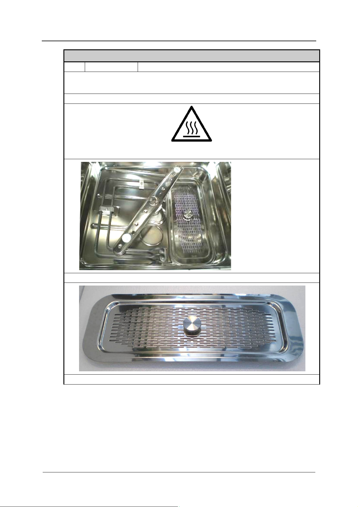
CLEANING OF FILTERS IN THE WASH CABINET
Warning:
Hot surface
Remove the drain water filtering assembly from the chamber.
Unscrew the threaded pin and remove the cover of the drain water filter basket.
REV.0.04_COD.610078_A4 Page 46
Page 47

MAINTENANCE
Clean the drain water filter basket. Remove residues deposited during various
washing cycles.
Remove and clean any deposits and incrustations from the washing chamber drain.
Place back the clean filter on the washing chamber drain.
Put the cover for the drain water filter back in place. Lock it in position with the
threaded pin.
Put the drain water filter group back in the wash chamber.
REV.0.04 _COD.610078_A4 Page 47
Page 48
MAINTENANCE
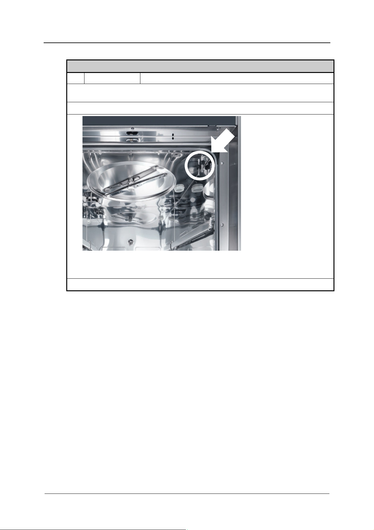
CLEANING OF WASHING CHAMBER THERMOSTAT PROBE
Operator: USER Frequency: 6 months
METHOD OF INTERVENTION:
Clean the washing chamber thermostat probe in the following manner:
Open the wash chamber door and remove the basket.
Visually check the washing chamber thermostat probe.
If deposits or lime incrustations can be seen clean thermostat probe using a damp
cloth and an appropriate detergent.
Take care not to damage or move the probe.
REV.0.04_COD.610078_A4 Page 48
Page 49

MAINTENANCE
CLEANING OF SPRAY ARMS
Operator: USER Frequency: every week
METHOD OF INTERVENTION: clean the spray arms as follows:
Open the wash chamber door and remove the basket.
Warning:
Hot surface
Unscrew the fastening pin of the two rotors and remove them from the chamber.
Unscrew the closure plug of the rear part of the nozzle and remove it.
Carefully clean and remove any incrustations from the washing rotor nozzles using
appropriate detergents.
Put the plugs back in place at the ends of the spray arms.
Make sure the gasket is properly positioned and in good condition. Replace it if
necessary.
Put the rotors back in the machine.
Lock them in place with the previously removed fastening pin.
REV.0.04 _COD.610078_A4 Page 49
Page 50

MAINTENANCE
14.5 Special maintenance
All special maintenance work is to be performed only by qualified, skilled personnel.
If your machine shows a functional anomaly so as to require a special maintenance, please
contact Miele Service.
Table of special maintenance tasks
Cleaning and checking operations
Frequency
Special
maintenance tasks
must be carried out
by Miele Service
after 1000
operating hours
or every 12
months
Action
Water solenoid filters: Check, clean and in case
Maintenance of dosing systems.
Temperature probes
Safety thermostat: sensor verfication.
Water solenoid valves: Check for any leakage.
Drain pump: Check for any leakage.
Check of pressure switches.
Check of piping and seals.
replace them.
Operator
SERVICE
REV.0.04_COD.610078_A4 Page 50
Page 51

PROBLEMS – CAUSES – REMEDY
15. PROBLEMS – CAUSES – REMEDY
15.1 Introduction
This chapter includes possible problems which may occur during machine operation, along
with their cause and solution.
If the inconveniences continue or take place frequently even after having carried out all the
instructions stated in this chapter, please contact Miele Service.
15.2 Problems (P.) – Causes (C.) – Remedy (R.)
P. MACHINE WILL NOT START:
C. Circuit breaker de-activated.
R. Place it in the "ON" working position.
C. Main switch de-activated
R. Place it in the "ON" working position
P. WASHING CYCLE DOES NOT START:
C. The door is not correctly closed or locked.
R. Check door closure. Check that the door microswitch is properly activated.
C. Microswitch failure
R. Check operation and replace as necessary
C. No detergent in tank.
R. Turn the machine off and fill the tank.
MACHINE DOES NOT REACH SET TEMPERATURE FOR THE SELECTED
P.
WASHING CYCLE:
C. The thermostat probe of the washing chamber is dirty or covered with lime.
R.
P. MACHINE DOES NOT PROPERLY RUN WASH CYCLE:
C. The nozzles of the spray arms are clogged with limescale.
R.
C. Water required for proper washing does not arrive.
R.
Clean the thermostat probe of the washing chamber, performing the routine
maintenance described in “MAINTENANCE” chapter of this manual.
Clean the nozzles or spray arms by carrying out the routine maintenance set
forth in “MAINTENANCE” chapter of this manual.
Ensure that the water is supplied at the correct pressure and that there are no
obstructions.
C.
R.
The correct amount of water required for correct washing cycle does not
arrive.
Completely close the tap for connection to the plumbing system located
upstream from the machine and clean the filter (by the technician (SERVICE)).
REV.0.04 _COD.610078_A4 Page 51
Page 52

PROBLEMS – CAUSES – REMEDY
P. DETERGENT FILLING PHASE DOES NOT OCCUR CORRECTLY:
C. Chemical dispensing pump is not working properly.
R.
C. Chemical dispensing pump failed.
R. Contact Miele Service.
Perform the routine maintenance set forth in “MAINTENANCE” chapter of this
manual.
REV.0.04_COD.610078_A4 Page 52
Page 53
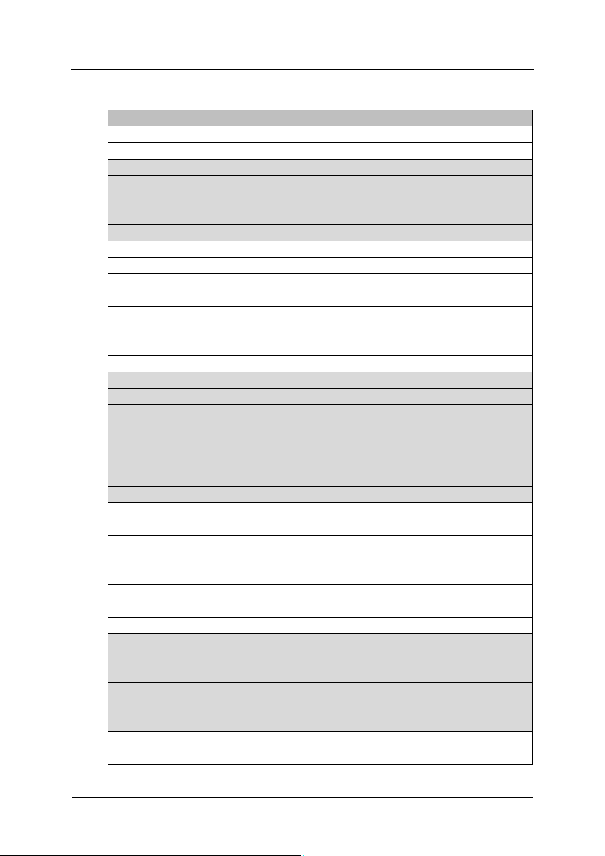
16. TECHNICAL DATA
Description Standard Metric
Max height 31.5“ 800 mm
Max altitude of operation 2000 m SLM
ELECTRICAL
Voltage 115V/1PH+N+GR / 60Hz 115V/1PH+N+GR / 60Hz
Power supply 1.6 kW/ 15A 1.6 kW / 15A
Fuse rating 1 x 20A 1 x 20A
Cable and min.section 3 x AWG 12 3 x AWG 12
COLD WATER
Connection ¾” male DN 20
Max flow rate 3.2 gpm 12 lt/min
Min flow pressure 14.5 PSI g 100 kPa
Max pressure 116 PSI g 800 kPa
Max temperature 59°F 15°C
Max hardness 70 ppm CaCO3 7°f
Max conductivity/ph n.a./7...8 pH n.a./7...8 pH
WARM WATER
Connection ¾” male DN 20
Max flow rate 3.2 gpm 12 lt/min
Min flow pressure 14.5 PSI g 100 kPa
Max pressure 116 PSI g 800 kPa
Max temperature 140°F 60°C
Max hardness 70 ppm CaCO3 7°f
Max conductivity/ph n.a./7...8 pH n.a./7...8 pH
DEMI WATER
Connection ¾” male DN 20
Max flow rate 3.2 gpm 12 lt/min
Min flow pressure 14.5 PSI g 100 kPa
Max pressure 116 PSI g 200 kPa
Max temperature 140°F 60°C
Max hardness 15 ppm CaCO3 1.5°f
Max conductivity/ph 30 µs/cm/5...8 pH 30 µs/cm/5...8 pH
MAIN DRAIN
Connection ½” 15DN Ø22 mm
Peak flow rate 3.5 gpm 13 lt/min
Max height 31.5” 0.80 m
Max temperature 200°F 93°C
PRINTER CONNECTION
Type RS232
TECHNICAL DATA
Hose L=2 m (78.7”)
REV.0.04 _COD.610078_A4 Page 53
Page 54

TECHNICAL DATA
ENVIRONMENT
Temperature +41…+104°F +5…+40°C
Relative humidity 20…90% no condensing 20…90% no condensing
Eq. noise pr. Lev. (Leq) <70 dB (A) <70 dB (A)
WEIGHTS
Total Net 143 lb 65 daN (kg)
Total Gross 160 lb 73 daN (kg)
Max on working 264 lb 120 daN (kg)
Floor load 3559 lb/ft“ 15 daN/m“ (kg/m“)
Foot support area 2.8 in“ 18 cmq
HEAT EMISSIONS
Max. from frames 1126 BTU 330 W
Max. from trolley (122°F) 1194 BTU 350 W
Overvoltage category
(according to IEC EN 60664
rule)
UL mark 61010-1
Certifications CAN/CSA-C22.2 No. 61010-1-04
Manufacturer address Steelco S.p.A.
II
CAN/CSA-C22.2 No. 61010-2-040
nd
UL, Std. No. 61010-1 (2
Edition)
IEC 61010-2-040:2006
Via Balegante, 27
31039 Riese Pio X - Italy
REV.0.04_COD.610078_A4 Page 54
Page 55

DISPOSING OF YOUR OLD MACHINE
17. DISPOSING OF YOUR OLD MACHINE
For environmental and safety reasons ensure the machine is completely drained of any
residual water, chemical residues and cleaning agents. Observe safety regulations and wear
safety goggles and gloves.
Make the door lock inoperable, so that children cannot accidentally shut themselves in. Then
make appropriate arrangements for its safe disposal.
Electrical and electronic appliances often contain valuable materials. They also contain
specific materials, compounds and components which were essential for their correct
function and safety. These could be hazardous to human health and to the environment if
disposed of with your domestic waste or if handled incorrectly. Please do not, therefore,
dispose of your old appliance with your household waste.
Please dispose of it at your local community waste collection / recycling center for electrical
and electronic appliances, or contact your dealer or Miele for advice. You are also
responsible (by law, depending on country) for deleting any personal data that may be stored
on the appliance being disposed of. Please ensure that your old appliance poses no risk to
children while being stored prior to disposal.
REV.0.04 _COD.610078_A4 Page 55
Page 56

Please have the model and serial number of
y
our machine available when contacting
Technical Service.
U.S.A.
Miele, Inc.
National Headquarters
9 Independence Way
Princeton, NJ 08540
Phone: 800-991-9380
Fax: 609-419-4241
www.mieleusa.com/professional
proinfo@mieleusa.com
Technical Service & Support
Phone: 800-991-9380
proservice@mieleusa.com
Steelco S.p.A.
Via Balegante, 27 31039 Riese Pio X (TV) – Italy
Canada
Importer
Miele Limited
Professional Division
161 Four Valley Drive
Vaughan, ON L4K 4V8
Phone: 1-888-325-3957
Fax: 1-800-803-3366
www.mieleprofessional.ca
professional@miele.ca
Miele Professional Technical Service
Phone: 1-888-325-3957
Fax: 1-800-803-3366
serviceprofessional@miele.ca
Alteration rights reserved / Publication date: 2021-04-14
 Loading...