

Installation instructions
Professional dishwasher
PG 8050i
To prevent accidents
and machine damage,
read these instructions
before
installation or use.
en - CA, US
M.-Nr. 07 865 040

Always read the "Warning and safety instructions" in the operations manual
before installing the dishwasher.
2

Contents
Installation .......................................................4
1. Installing the steam deflector (if applicable) ............................6
2. Installing the dishwasher under the countertop .........................7
Installing the slides ...............................................7
Mounting brackets ...............................................8
Leveling legs....................................................9
3. Aligning the control panel with the drawer fronts .......................10
4. Fitting the front panel .............................................11
Fitting the mounting bracket .......................................11
5. Securing the dishwasher to the countertop............................15
6. Adjusting the door springs ........................................16
7. Installing the toekick .............................................17
3

Installation
Integrated ("i") dishwashers
"i" models are designed for installation
under a continuous countertop.
The control panel with accessories is
–
enclosed in a separate package for
on site installation.
The front is designed for a custom
–
made panel to match the existing
kitchen cabinets.
The dishwasher does not have a
–
toekick. The toekick area of the
dishwasher needs to be covered
either with the toekick board of the
kitchen cabinets or with a separate
one. The height of the dishwasher
toekick can be adjusted to match
that of adjacent cabinets. The
toekick recess depth is also
adjustable.
All instructions necessary for installing
the dishwasher are described in the
following text.
To ensure stability, these
,
dishwashers should only be installed
under a continuous countertop and
securely fastened to the cabinet
base units.
The dishwasher should not be
,
installed underneath a cooktop. The
radiant heat generated by the cook
top may damage the dishwasher.
4
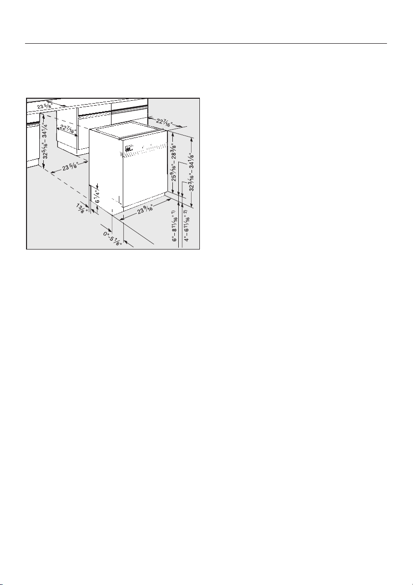
Dimensions
Dishwasher model PG 8050i
1) with 34 7/8" (870 mm) machine height
2) with 32 1/4" (820 mm) machine height
Range of adjustment is approximately
2" (5 cm).
Installation
Machine heights between 35" and 37"
can be obtained if the supplied legs are
removed and extended legs are
attached. Please contact the Miele
Technical Service Department for the
appropriate legs.
5
Installation
1. Installing the steam
deflector (if applicable)
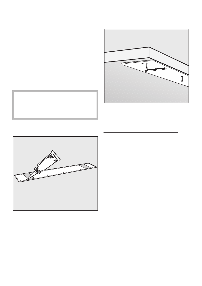
A stainless steel coverplate is supplied
to protect the underside of the
countertop against steam rising from
the dishwasher when the door is
opened. If the countertop is made of
Corian(r), granite, marble or other solid,
waterproof material, the steam deflector
should not be used.
If two different materials meet up
,
at the front edge of the countertop,
then the join must be concealed by
the cover plate.
^ Remove the protective backing from
the cover plate.
Nail the cover plate to the underside
^
of the countertop with the nails
provided.
Countertops with wood or laminate
edging:
^ Hammer the nails through the back
row of holes.
^
Squeeze sealant from the supplied
tube all the way along the hollow
molding in the cover plate.
^
Align the cover plate to the front
edge of the countertop in the middle
of the niche.
6
^ Use soapy water to wipe off any
excess sealant.

Installation
2. Installing the dishwasher
under the countertop
For ease of service and quick
disconnection, it is best to install the
machine so that the water and
electricity supplies can be accessed
through an adjacent cabinet, rather
than situating them behind the
machine.
If the electrical and water supplies are
located behind the machine the
dishwasher will have to be removed
from the cabinet for service. See the
"Plumbing" and "Electrical" sections for
proper connection procedures before
continuing. If electrical and water
supplies are not located in adjacent
cabinetry it is extremly important that
the toekick is removable.
Installing the slides
Two slides are included and should be
installed on the feet of the dishwasher
before the machine is pushed under
the countertop. This will allow the
machine to slide easier, protect the
floor, and allow adjustment of the rear
leveling legs from the front of the
machine.
Adjust the height of the legs so that
^
the top of the dishwasher is roughly
1/4" (5 mm) below the countertop.
Tipping the machine slightly to the rear,
if possible, will make adjusting the front
legs easier. Make sure the machine is
level when adjustments are complete.
,
There must be no electrical
outlet behind the dishwasher. Risk of
overheating and fire if the
dishwasher were to be pushed up
against a plug.
^
Place the slides, with the ratchet at
the rear, under the dishwasher legs.
7

Installation
Mounting brackets
To ensure stability this dishwasher
should be securely attached to the
countertop (step 6). Two mounting
brackets are included for this purpose.
^ Insert the tab of each bracket into the
guide holes on the top.
Stone or marble countertops:
For these countertops the dishwasher
must be secured to the adjacent
cabinets. Special brackets must be
used, see "Accessories".
The drain hose connection at the rear of
the dishwasher can be turned to allow
the hose to be angled to the right or
left.
^ Push the machine into the opening,
making sure the electrical cable and
hoses can reach their connection
points without kinks.
8

Leveling legs
^ Adjust the rear leveling legs to the
required height with a T20 Torx
screwdriver.
To raise the machine - turn clockwise.
To lower the machine -turn counter
clockwise.
Several turns may be needed to set the
correct height. A low speed electric or
cordless screwdriver can also be used.
Installation
^ Adjust the front leveling legs by
pushing on the feet with a slotted
screwdriver.
The dishwasher should be raised
until it just touches the underside of
the countertop.
9

Installation
3. Aligning the control panel
with the drawer fronts
The control panel can be aligned with
^
the drawer fronts of the kitchen
cabinets by adjusting the spacer
bars.
^ Using an 1/3" (8 mm) socket, turn the
nut clockwise or counterclockwise
until the spacers reach the required
height.
If necessary, individual (or all) spacer
bars can be removed.
To remove the spacer bars from the
^
control panel, place the panel on a
table, printed side up, and gently
push down on the spacer bars at a
point near the bottom of the control
panel. This will release the mounting
bolts from their slots.
Adjustment range
from 4 1/2" control panel with(112 mm): out spacer bars,
to 5 3/4" control panel with
(145 mm): four spacer bars,
to 6" using a fifth spacer bar
(154 mm): (optional accessory).
10
After adjusting the control panel
height, cut off the plastic screw
excess.

Installation
4. Fitting the front panel
Mounting brackets are already fitted on
stainless steel door fronts. These fronts
cannot be shortened. (Go to "Fitting
and securing the door front".)
The door of a kitchen base unit (without
drawer front or fittings) is normally used
for the front panel.
If a kitchen door front is not available, a
panel with the following dimensions
may be used:
Width:
23 1/4" - 23 1/2"
(590 - 597 mm)
Thickness:
the same thickness as the adjacent
front panels, but at least 2/3" (16 mm).
Height:
Dimension X
Fitting the mounting bracket
A mounting bracket must be fitted to
the rear of the front panel.
Templates are provided to position the
mounting bracket and the front panel
correctly.
^ Place a template on each end of the
bracket as shown, making sure the
rule marks face the outside of the
bracket.
11

Installation
Hang the bracket on the machine
^
door.
^ Slide the top edge of the templates
under the spacer bars and control
panel.
^ Slide the mounting bracket up or
down until the oblong holes on the
machine door align with the
corresponding marks on the template
(as shown in the left side of inset a
^ Draw a line on each template that is
even with the top edge of the
adjacent cabinet door (inset b).
12
^ Remove the bracket from the door.
^
Place the door panel on a flat
surface, good side facing down,
taking care not to scratch the
surface. Make certain that the bottom
of the panel is closest to you.
^
Place the bracket on the back of the
door panel and adjust it so that:
–
the lines drawn on the templates
align with the upper edge of the door
panel and;
–
the mounting bracket is centered (left
to right) on the door panel.

Tape the bracket to the door panel to
^
hold it in place while the mounting
holes are being drilled.
^ Proceed to step "Drill pilot holes ...".
If the adjacent cabinetry (or
appliance) does not have drawers
and alignment to a drawer line is impossible:
Installation
Remove the bracket from the
^
machine door and place it on the rear
of the door panel so that:
– the bracket is centered left to
right,
and
– the bottom of the bracket is
aligned with the (X) line.
Tape the bracket to the door panel to
^
hold it in place while the mounting
holes are being drilled.
^ Hang the bracket on the machine
door, without the templates, and
tighten the four locking screws on the
edges of the door panel.
^
Close the door.
^
Measure the distance from the
adjacent cabinet (or appliance) door
bottom to the bottom of the mounting
bracket (X).
^
Using measurement (X), draw a line
on the rear of the door panel (X)
inches up from the bottom.
^
Drill pilot holes for the screws using a
3/32" (2.5 mm) bit.
^
Attach the bracket to the panel using
the 6 screws provided.
^
Remove the templates (if used).
The templates should be kept in
case you want to install a different
door panel on the dishwasher at a
later date.
13

Installation
Attach the panel to the dishwasher
^
by aligning the bracket tabs with the
slots on the door.
Push up one side of the door panel
^
until it touches the spacer bars (or
control panel if spacer bars are not
being used) and lightly tighten the
T20 Torx screws on the
corresponding edge of the machine
door.
Repeat the process with the other
^
side of the door panel.
Shut the door.
^
Check that the door panel is adjusted
^
correctly. It should be snug at the top
and neatly aligned with the cabinet
drawer and door lines. If it is not
aligned properly, loosen the Torx
screws and readjust the panel
Once the door panel is positioned
correctly:
^ Open the dishwasher door.
^ Tighten all the Torx screws on the
edges of the dishwasher door.
^
Open the dishwasher door slightly. If
the locking screws on the edge of the
dishwasher door can not be reached,
the dishwasher will have to be pulled
out of its opening a few inches.
14
^ Use the provided caps to plug the
locking screw access holes.
,
Front panels differ in weight and
it is therefore essential that the door
springs are adjusted after the front
panel has been fitted! See Step 6.

5. Securing the dishwasher to
the countertop
Open the dishwasher door.
^
If a steam deflector is installed
under the countertop, the bracket
holes must align with the slots in the
deflector.
Installation
^ Using flat head screws, secure the
dishwasher to the countertop by
screwing through both the mounting
bracket and the steam deflector.
Make certain that the white rubber
seal located at the top, outer edge
of the dishwasher is tight against the
bottom of the countertop.
Do not drill any additional holes
through any portion of the wash
cabinet. If in doubt on how to secure
the dishwasher, please call the
Miele Technical Service Department.
15

Installation
6. Adjusting the door springs
Open the dishwasher door halfway.
^
If the door remains in this position when
released, the springs are adjusted
correctly.
If the door drops, the tension on the
springs needs to be increased.
If it closes on its own, the tension on the
springs needs to be decreased.
The adjusting screw is located behind
the door in the upper front strip, on the
left hand side of the dishwasher.
Please note:
If the door front is too heavy for the
door springs (i.e. the door falls open),
then stronger springs should be fitted.
Please contact your Miele dealer or the
Miele Service Department for advice.
Open the dishwasher door halfway.
^
The door springs are easier to adjust
when the door is only half open.
^ To adjust the door springs use a T20
Torx or a small slotted screwdriver
and turn the screw:
- clockwise to increase the tension
- counterclockwise to decrease
the tension.
16

Installation
7. Installing the toekick
The base area of the dishwasher is
normally covered with the toekick board
of the kitchen cabinets.
To prevent damaging the front
panel, and before installing the
toekick, measurements must be
taken to ensure that the toekick will
not interfere with the complete
opening of the dishwasher door.
The panel overhang (P), and toekick
depth of recess (R), determine the
maximum dishwasher toekick height
(H).
Place the toekick board directly in
^
front of the kitchen cabinet base run,
but do not attach.
Carefully open the dishwasher door.
^
If the front panel comes into contact
with the toekick when the dishwasher
door is opened, the toekick in the area
behind the dishwasher door needs to
be cut to size.
To do this, mark where the edge of
^
the front panel comes into contact
with the toekick.
Cut the toekick to size along this line.
^
^ Place the toekick in front of the
kitchen cabinet base run again and
check whether the dishwasher door
can be opened fully.
If it cannot, trim the toekick again
until the correct size is achieved.
^ Secure the toekick board to the
adjacent kitchen cabinets in
accordance with the instructions of
the kitchen cabinet manufacturer.
If your kitchen does not have a toekick
board matching the kitchen cabinets,
you can purchase a toekick kit to cover
the toekick area (special accessory).
171819


Alteration rights reserved / Publication date: 08/24/2010
M.-Nr. 07 865 040 / 01
 Loading...