


Operating instructions
Gas hob
KM 81-2
It is essential to read these
operating instructions before
installing or using the machine,
to avoid the risk of accident
or damage to the machine. M.-Nr. 04 647 380
Q\
Description of the appliance
Description of the appliance
KM 81-2
2
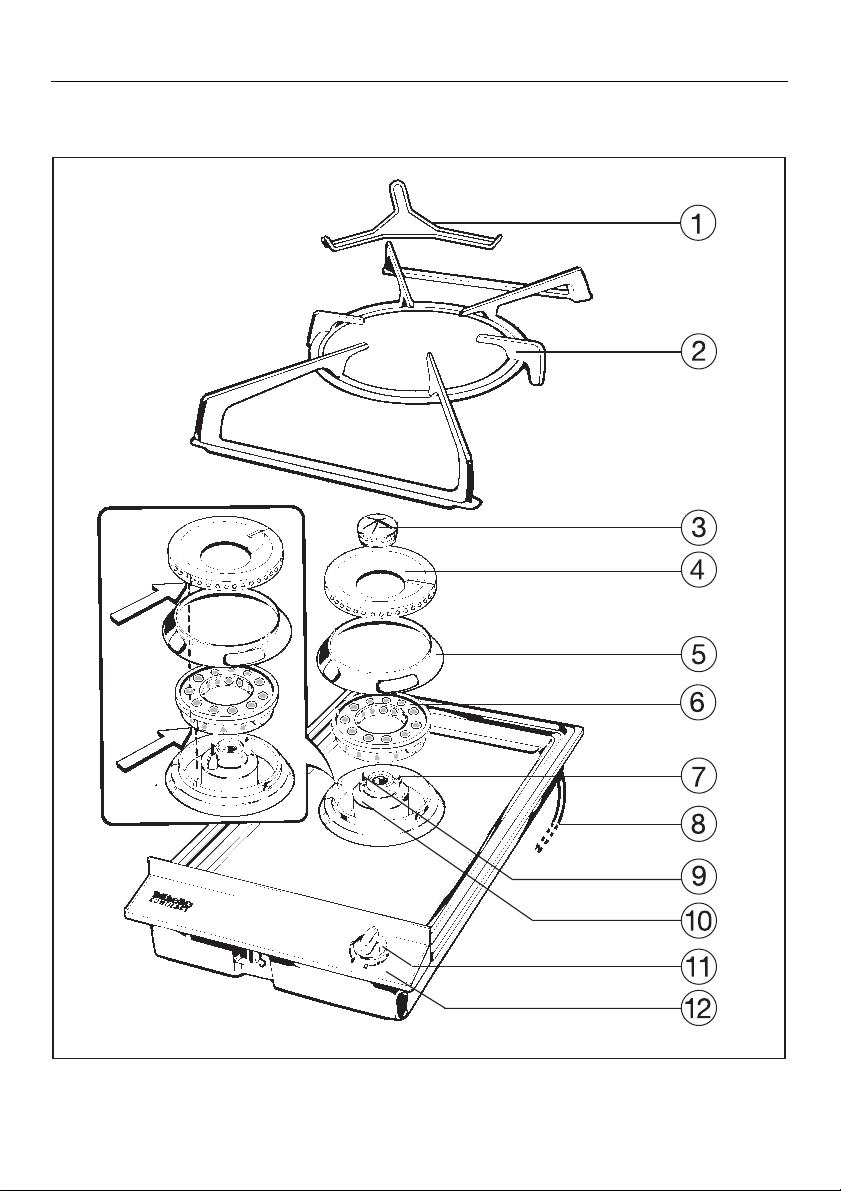
Description of the appliance
KM 81-2
b Trivet
c Wok/pan support
d Small burner cap
eLarge burner cap
f Burner collar ring
Large burner cap base
g
h Ignitor
i Cable for connection
to electrical supply approx. 3.6 ft
(1.10 m) long.
j Ignition safety control
k Burner base
l Control for burner
m Control panel
Description of the appliance
Data plate
Because the data plate is no longer
visible once the appliance has been
built in, a 2nd data plate is supplied
which should be placed into the space
provided in these instructions under
"After Sales Service".
Special accessories
Special accessories are available from
your Miele Dealer or from the Spare
Parts Department.
Stainless steel cover-EA 80
A stainless steel cover is available for
the KM 81-2 hob. Check availability in
each country.
For installation of the cover, a minimum
distance of 650 mm is required between the work surface and wall units.
Note:
The wok/pan support should be
removed before the cover is closed
down over the hob.
Do not install the DA 8-2 directly
next to the gas hob.
3

Contents
Contents
Warning and Safety Instructions . . . . . . . . . . . . . . . . . . . . . . . . . . . . . . . . . . . . . 6
For the user
Description of the appliance . . . . . . . . . . . . . . . . . . . . . . . . . . . . . . . . . . . . . . . . . . 2
Gas safety / Environment . . . . . . . . . . . . . . . . . . . . . . . . . . . . . . . . . . . . . . . . . . . . . 5
Gas burner unit
Burner control . . . . . . . . . . . . . . . . . . . . . . . . . . . . . . . . . . . . . . . . . . . . . . . . . . . . 10
Instructions for using the gas burner. . . . . . . . . . . . . . . . . . . . . . . . . . . . . . . . . . . 10
Power cut . . . . . . . . . . . . . . . . . . . . . . . . . . . . . . . . . . . . . . . . . . . . . . . . . . . . . . . . 12
Suitable pans and woks. . . . . . . . . . . . . . . . . . . . . . . . . . . . . . . . . . . . . . . . . . . . . 13
Cleaning and Care. . . . . . . . . . . . . . . . . . . . . . . . . . . . . . . . . . . . . . . . . . . . . . . . . 14
Problem solving guide . . . . . . . . . . . . . . . . . . . . . . . . . . . . . . . . . . . . . . . . . . . . . . 16
After Sales Service. . . . . . . . . . . . . . . . . . . . . . . . . . . . . . . . . . . . . . . . . . . . . . . . . 17
For the installer / electrician / engineer
Electrical connection, GB / IRL . . . . . . . . . . . . . . . . . . . . . . . . . . . . . . . . . . . . . . . 18
Gas connection GB / IRL. . . . . . . . . . . . . . . . . . . . . . . . . . . . . . . . . . . . . . . . . . . . 20
Appliance dimensions . . . . . . . . . . . . . . . . . . . . . . . . . . . . . . . . . . . . . . . . . . . . . . 21
Instructions for building-in . . . . . . . . . . . . . . . . . . . . . . . . . . . . . . . . . . . . . . . . . . . 22
Clearance above and around the appliance . . . . . . . . . . . . . . . . . . . . . . . . . . . . . 25
Conversion to alternative types of gas. . . . . . . . . . . . . . . . . . . . . . . . . . . . . . . . . . 26
4
Gas safety Environment
Gas safety Environment
WARNING:
If the information in this manual
is not followed exactly, a fire or
explosion may result causing
property damage, personal injury
or death.
WHAT TO DO IF YOU SMELL GAS
– If you smell gas you must act
immediately.
– Extinguish any flames.
– Do not create any electrical
sparks, e.g. do not insert or withdraw any electrical plugs or operate electrical switches such as
lights and door bells.
– Do not enter a room with an open
light when there is a smell of gas.
Disposal of the packing material
The transport and protective packing
has been selected from materials
which are environmentally friendly for
disposal and can normally be recycled.
Rather than just throwing these materials away, please ensure they are offered for recycling.
Disposal of your old
machine / appliance
Old machines / appliances contain materials which can be reclaimed or recycled. Please contact your dealer,
your local waste collection centre or
scrap merchant about potential recycling schemes, before disposing of the
machine/ appliance. Ensure that it presents no danger to children.
See the appropriate section in the
Warning and Safety instructions.
– Do not light cigarettes or matches.
– Do not smoke.
– Open all windows and doors.
– Close any shut-off valves at the
gas connection or mains supply
immediately.
– Shut off the gas valve next to the
machine.
– If all gas valves are closed but
there is still a smell of gas in the
room you should call your local
gas supplier immediately.
5
Warning and Safety Instructions
Warning and Safety Instructions
Important safety instructions
This appliance complies with all relevant legal safety requirements. Improper use of the appliance can,
however, present a risk of both personal injury and material damage.
Before installing and using the appliance for the first time, read the
operating instructions carefully.
They give information on safety, on
the operation and care of the appliance. This way you will avoid the
risk of accidents and damage to the
appliance.
Do not let children access the appliance or its controls. Supervise its
use by the elderly or infirm.
Keep these instructions in a safe
place and pass them on to any future user.
Correct usage
This appliance is intended for do-
mestic use, and in particular to
cook, fry or reheat food. Any other
usage is at the owner’s risk and could
be dangerous. The manufacturer cannot be held responsible for damage
caused by improper use of the appliance.
Technical safety
the information on the data plate.
You should find out details about the
type of gas and calorific value from
your Gas supplier and compare this information with the type of gas quoted
on the data plate.
They must correspond.
when continuity is complete between
the appliance and an effective earthing
system.
It is imperative that this basic safety requirement be tested and where there is
any doubt, the electrical system of the
house should be checked out by a
qualified electrician. The manufacturer
cannot be held responsible for damage
such as electric shock caused by the
lack or inadequacy of an effective earthing system.
been built-in. This is necessary to ensure that all electric components are
shielded.
way that they do not touch any parts of
the appliance which become hot. This
could cause damage.
Please ensure that the domestic
electrical supply corresponds to
The electrical safety of this appliance can only be guaranteed
For safety reasons the appliance
must only be operated after it has
Ensure that the gas pipe and electrical cable are installed in such a
6
Warning and Safety Instructions
Warning and Safety Instructions
Installation work and repairs may
only be carried out by a suitably
qualified and competent person,e.g.
’Corgi’ registered for gas in G.B.
Repairs and other work by unqualified
persons could be dangerous.
The appliance is only completely
isolated from the electrical supply
when it is switched off at the wall
socket, or the mains fuse is withdrawn,
or the screw-out fuse is removed (in
countries where this is applicable). Do
not pull by the mains cable, but by the
plug when withdrawing the plug from
the socket.
Do not connect the appliance to the
mains electrical supply by an extension lead. Extension leads do not guarantee the required safety of the appliance.
Gas burners should only be used
in rooms with adequate ventilation.
Ensure that the worktop area around
the hob is clear of obstacles to allow
sufficient ventilation.
Important notes for the installer
Check that all parts of the burner
unit are correctly assembled before igniting the gas, otherwise the ignition could malfunction.
Please note the following, in cases
where the hob is on LPG supply:
Where this appliance is installed in
marine craft or in caravans, it shall not
be used as a space heater.
When installing the gas hob, the
following minimum dimensions
must be kept:
25 cm distance from any heat-sensitive material or surfaces, otherwise
some form of insulation must be
fitted.
65 cm between the hob and a wall
unit above it.
65 cm between the hob and a
cooker hood above it.
Wall sealing strips and any back-
moulding must be of heat resistant
material.
7
Warning and Safety Instructions
Warning and Safety Instructions
Important notes for the user
Do not let small children use the
appliance or touch it during operation. Not only do the cooking areas
heat up, but also the control panel.
Danger of burning. Keep all pans out of
the reach of children.
Make sure that there is a minimum
distance of 15 mm between the
pot or pan and the control panel. Never
place a pot on the control panel.
When using an electric socket
near the hob, care should be taken
that the cable of the electrical appliance does not come into contact
with the gas flames or the hot parts of
the hob.
Note that potential hazards may
exist with overhead cabinets.
The wok/pan support and trivet (if
supplied) heat up when the burners are in use. Do not touch them until
they have cooled down. The use of
oven gloves is recommended.
Do not let cooking grease or other
flammable materials accumulate
on the unit.
Never leave the hob unattended
when cooking with oil or fat. Very
hot oil can cause a fire. Always heat fat
slowly, watching as it heats.
Before removing pots and pans,
be sure to turn the control to “OFF”.
Allow sufficient time for the unit to
cool before touching or exposing
surface areas to flammable materials.
Always ensure that food is suffi-
ciently cooked or reheated.
Many factors will affect the overall cooking time, including the size and amount
of food, its temperature, changes to the
recipe and the shape and size of cooking container.
Some foods may contain micro organisms which are only destroyed by
thorough cooking, therefore when cooking or reheating foods, e.g. poultry, select a longer cooking or reheating time.
It is essential to ensure that food
has been evenly and sufficiently
heated. Turn or stir during cooking if
necessary, and check that it is thoroughly cooked.
Never use damp potholders.
Use only suitable cookware. Unsuit-
able cookware may break due to a
sudden temperature change.
Avoid allowing liquids or foods con-
taining salt to spill on to a stainless
steel hob. Should this happen, wipe up
any spillages containing salt immediately, otherwise discoloration could occur.
When frying foods, make sure that
the food is as dry as possible so
as to prevent moisture from causing hot
fat to bubble over.
When shallow or deep frying, do
not overfill the pan with oil.
8
Warning and Safety Instructions
Warning and Safety Instructions
When using a cooker hood over the
gas hob, ensure that any burners in
use are always covered with a pan.
Do not flambé under a cooker hood.
Otherwise flames could be drawn
up by the suction of the cooker
hood, parts of which could then be
damaged. Fat residues in the filter
could catch fire.
Do not use the gas hob to heat up
the room. The high temperatures of
the hob could cause inflammable objects in the vicinity to burn.
Do not use spray aerosols in the
vicinity of the appliance while it is
in operation.
Under no circumstance use a
steam-cleaning appliance to clean
the gas hob.
The steam could penetrate to live components and cause a short circuit.
Disposal of discarded appliances
Before disposing of an old ma-
chine / appliance, ensure that disconnection from the gas supply is
made by a suitably competent person.
Switch off at the mains, disconnect and
remove the appliance cable at both
ends and render useless. This is intended to prevent the discarded appliance from being a hazard.
The manufacturer cannot be held
liable for damage caused by noncompliance with safety instructions.
In countries which may be subject
to infestation by cockroaches or
other vermin, pay particular attention to
keeping the appliance and its surroundings in a clean condition at all times.
Any damage which might be caused
by cockroaches or other vermin will not
be covered by the appliance guarantee/warranty.
Spray canisters, aerosols or in-
flammable substances must not be
stored in a drawer beneath the hob.
Any cutlery trays must be made of a
heat resistant material.
9
Gas burner unit
Gas burner unit
Before using for the first time, take
heed of the “Warning and Safety
Instructions”.
Burner control
The inner and outer burner are both
controlled by one knob.
The burner control knob may only
be turned anti-clockwise to switch
on and back in a clockwise direction to switch off. Otherwise the control could be damaged.
The gas flame is lit by electrical ignition.
When the burner control is pressed in the
strong flame position, a spark passes
from the electrode to the burner and ignites the gas to give a flame (see
page 11).
The burner is equipped with an ignition
safety device. If a gas flame goes out, for
example, if food boiled over, or if there
was a sudden draft, the ignition safety
control cuts off the supply of gas.
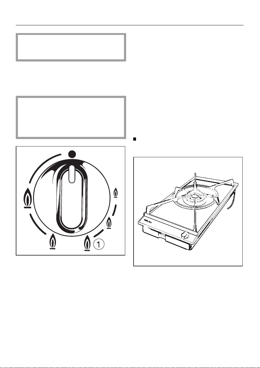
Instructions for using the hob
Place the wok or the pan on the
wok/pan support.
X Gas switched off
&
Strong flame (outer and inner rings
both produce high flames)
& Lower flame (outer ring on low)
& Intermediate state b (provides
ignition for outer ring from inner ring)
/ Very low flame
(inner ring on high, outer ring off)
/ Lowest flame
(inner ring on low, outer ring off)
10
A trivet is supplied with the gas hob. It
is designed to sit on the wok/ pan support when using small pans. The trivet
should only be used on the burner with
the lowest setting. It should only be
used with pans with a diameter of less
than 10 cm.

Gas burner unit
Press in the control knob and turn
anti-clockwise to the high setting (largest flame symbol).
When the flame ignites, keep the control pressed in for 5-10 seconds, and
then press down once more firmly
before letting go.
Gas burner unit
Turn the control knob to the highest
setting for boiling or searing food,
the lower setting for continuing cooking and for keeping food warm.
Turn the control knob down to a lower
setting in good time in order to prevent
food from boiling over or burning.
If the flame goes out, repeat the procedure, keeping the control knob pressed
in for a few extra seconds.
If, after several attempts the gas still
does not burn, check whether the lugs
are correctly positioned, for the large
burner cap in the notch in the large
burner cap base, and for the large burner cap base in the notch in the burner
base.
To turn the heat down from the
highest to the lowest setting, turn the
control anti-clockwise until there is a
resistance, (intermediate stage
press in and continue to turn the
control anti-clockwise to the
desired setting.
To turn the heat up from the lowest to
the highest setting, turn the control
clockwise until there is a resistance,
(intermediate stage
continue to turn clockwise to the
high setting.
To switch the burner off, turn the control knob in a clockwise direction to
X
" position. The flame will go out.
the "
& b), press and
& b),
11

Gas burner unit
Gas burner unit
Power cut
If there is an interruption to the electrical supply, the gas can be ignited with
a match.
Light a match, press in the burner control and turn anti-clockwise to the highest setting (large flame).
With the control knob pressed in, ignite
the gas at the burner with a match.
Keep the control knob pressed in for
a further 5-10 seconds, and then
press firmly down once again before
letting go.
Important:
Only woks/pans with a max.
diameter of 280 mm should be used
on the gas hob.
If woks/pans have a larger diameter,
the flame may spread out to the sides
of the wok or the pan and damage or
burn the worktop or surrounding units.
The outer part of the gas flame is much
hotter than the centre. Therefore the
tips of the flame should be in contact
with the base of the pan and not
spread out to the sides. Flames which
spread out to the sides of the pan
merely warm up the air in the room.
When using the hob ensure the following minimum distances are maintained:
50 mm between the wok or the pan
and heat sensitive worktop or surrounds.
With too small a distance the flame
may spread out from the wok or the
pan and damage or burn the worktop or surrounding units.
15 mm between the wok or the pan
and the control panel.
Never place a pan on the control
panel.
12

Gas burner unit
Suitable woks, pots and pans
Material
Most woks and pans can be used for
cooking on gas.
Wok / Pan base
Bases do not need to be even for gas
cooking, in contrast to those used on
electric burners. Through the spreading action of the flame, heat reaches all
parts of the base.
Thin bases conduct heat to the food inside more quickly than thicker ones.
Since heat is not evenly distributed
over the pan base, there is a danger
that food may be overheated in places.
Therefore, when using saucepans with
thin bases, stir the food more often.
Thick bases lessen the risk of food
overheating in places, as better distribution of heat is possible.
Gas burner unit
Wide, flat pots are more suitable than
narrow, tall ones, since they heat up
more quickly.
Lids
Less heat is lost by cooking in a
covered pot.
Shape of woks, pots and pans
Using a small wok / pan on the strong
flame does not mean faster cooking
but simply results in wasteful gas consumption. The correct procedure is to
cook with small pots on the low flame
and large ones on the strong flame.
small pots = low flame
large pots = strong flame
13

Cleaning and care
Cleaning and care
In the event of a pan boiling over, clean
the burner and the hob surface immediately, to prevent the boiled over substance from burning on.
Burner unit
The burner unit can be dismantled for
cleaning when cold.
Burner caps
The burner caps and collar ring can be
cleaned with a solution of dishwashing
liquid.
Do not use any caustic cleaners,
scouring powders, knives or hard
brushes, as these will cause scratches.
With time and use, the surface of the
burner caps will become dull.
Reassembling the burner unit
Important: The burner must be correctly fitted together before it is lit,
otherwise the ignition device could
be damaged.
Electronic ignition
The ignition device electrodes on
the burner must always be dry,
otherwise they will not spark.
From time to time, the electrodes
should be wiped with a well wrung-out
cloth and wiped dry with a clean cloth.
Important: Do not damage the ignition electrodes and the thermo
element of the ignition safety device.
14
When fitting the large burner cap base
to the burner base, ensure that the locating lug fits exactly into the appropriate notch.
Place the burner collar ring onto the
large burner cap base.
Place the large burner cap onto the
large burner cap base, ensuring that
the locating lug fits exactly into the appropriate notch.
Fit the small burner cap.

Cleaning and care
Wok/pan support, trivet
Cleaning and care
Control panel / Control knob
Caution: the wok/pan support and
trivet become hot in use.
The wok/pan support and trivet can be
removed for cleaning, and cleaned in a
hot solution of washing up liquid.
Never use scouring agents as these
could scratch the surface.
Dry with a cloth.
Hob surface
Avoid allowing liquids or foods containing salt to spill on to the stainless steel hob. Should this happen,
wipe up any spillages immediately.
Otherwise discoloration could occur.
Remove dust, oils and fats, spillages of
foods and condensed water from pots
and pans immediately to prevent them
from drying on.
Do not use any scouring agents or
pads on the knob or control panel,
as these could cause damage.
Clean the control knob and the control
panel with hot water and a little dishwashing liquid.
After application, rub dry with a clean
cloth.
Under no circumstances use a
steam-cleaning appliance to clean
the gas hob. The steam could penetrate to live components and cause
a short circuit.
Dried on food residues are easier to
remove if they are first softened with
warm water.
Clean the hob surface using hot water
with a little dishwashing liquid.
Do not use any scouring agents or
pads, knives or hard brushes.
These will cause scratching.
Do not use cleaning agents containing acids.
A proprietary cleaning agent for stainless steel can be used on the stainless
steel hob surface.
15

Problem solving guide
Problem solving guide
Repairs to the gas and electrical
components of this appliance must
only be carried out by a suitably
qualified person. Repairs by unauthorized personnel could be dangerous.
However some minor problems can be
resolved as follows:
. . . the gas flame goes out after
being lit
Check whether the burner caps are
correctly positioned.
Follow the procedure on how to start
the flame from top left of page 11, do
not forget to press the control right in
before releasing after 5–10 seconds.
What to do if . . .
. . . the burner does not ignite after
several attempts
Check whether:
the burner caps are correctly positioned, and are dry and clean.
the gas supply tap is turned on.
a mains fuse has blown. In this case
call an electrician or the Miele Service Dept.
Use a match to light the gas
(see page 10).
. . . the shape and colour of the flame
are suddenly different from usual
Check whether the parts of the burner unit are correctly assembled.
. . . the electric spark ignition for the
gas burner no longer works
Check whether food residues or
cleaning agents have collected
between the ignition electrode and
the burner.
Clean these away carefully. Do not let
the electrode get wet.
Check, whether the orifices of the
small burner cap are clean, especially those toward the tip of the ignition electrode.
16
After Sales Service
After Sales Service
In the event of any fault which you cannot remedy yourself, please contact:
Your Miele Dealer
or
The Miele Service Department
The address of the nearest Service
Department is given on the back page.
When contacting the Service Department, please quote the Model and Serial No. of the appliance, both of which
can be found on the data plate.
Space for data plate
17

Electrical connection UK, IRL
Electrical connection UK, IRL
Electrical connection of the appliance should be undertaken by a
suitably competent person in strict
accordance with national and local
safety regulations.
The appliance is supplied with a mains
cable for connection to single phase
230-240 V, 50 Hz supply (GB), 220 V,
50 Hz (IRL). The fuse rating and rated
load are given on the data plate.
Connection should be made by a fused
connection unit or a switched socket
which complies with local and national
regulations and is accessible after the
appliance has been built-in.
For extra safety it is advisable to install
a residual current device (RCD), with a
trip current of 30 mA.
Important:
The wires in the mains lead are coloured in accordance with the following
code:
The wire which is coloured blue must
be connected to the terminal which is
marked with the letter N or coloured
black.
The wire which is coloured brown must
be connected to the terminal which is
marked with the letter L or coloured red.
WARNING
THIS APPLIANCE MUST BE
EARTHED.
Any replacement connection cable
must be 3 x 1 mm
2
.
Green/yellow = earth
Blue = neutral
Brown = live
As the colours of the wires in the mains
lead of this appliance may not correspond with the coloured markings identifying the terminals in your plug, proceed as follows:
The wire which is coloured green and
yellow must be connected to the terminal in the plug which is marked with the
letter E or by the earth symbol z or coloured green or green and yellow.
18

Electrical connection UK, IRL
Non rewireable plugs BS 1363
If this machine or appliance is fitted
with a non-rewireable plug, the following information applies:
If the socket outlets are not suitable for
the plug supplied with this product, it
must be cut off and an appropriate
plug fitted.
The plug cut from the flexible cord
should be disposed of and on no account be inserted into a socket elsewhere in the house (electric shock
hazard).
The fuse cover must be refitted when
changing the fuse, and if the fuse
cover is lost, the plug must not be used
until a suitable replacement is obtained. The colour of the correct replacement cover is that of the coloured
insert in the base of the plug, or the colour that is embossed in words in the
base of the plug (as applicable to the
design of plug fitted).
Electrical connection UK, IRL
The correct fuse rating of the replacement fuses that are ASTA approved to
BS 1362 should be fitted.
Replacement fuse covers may be purchased from your local electrical suppliers, or Miele Service Agent.
19

Gas connection
Gas connection
Connection to the gas supply, or
conversion from use on one type of
gas to another should only be
undertaken by an approved Corgi
registered fitter, who is responsible
for correct functioning of the appliance when installed.
The gas hob is suitable for natural gas
and LPG, and is supplied as standard
for connection to natural gas.
Check with your local Gas Supplier
for details about the type of gas and
calorific value and compare this information with the type of gas
quoted on the data plate.
For LPG consult your Miele-Dealer
or the Service Department for the
correct gas jet kit.
Instructions for conversion to alternative forms of gas can be found in the
following Section.
The gas connection must be installed so that it can be connected
either from inside or outside the kitchen unit and the stop-valve must
be easily accessible and visible, by
opening one of the furniture doors,
if necessary.
The appliance may only be connected
by a registered gas fitter (eg Corgi in
the UK), who is responsible for correct
functioning of the appliance when installed.
When the gas hob has been installed, it is essential to check that
neither the gas pipe nor the mains
cable are in contact with hot parts
of the appliance, otherwise temperature damage to the pipe and the
cable could occur.
Nominal rating for all types of gas at
the high setting:
Gas type kW
Burner Natural gas
Liquid gas
Nominal rating for all types of gas at
the low setting:
Gas type kW
Burner Natural gas
Liquid gas
Contact your local gas supplier if the
natural gas connection pressure is less
than 18 mbar or higher than 25 mbar.
5.75
5.40
0.20
0.20
An appropriate rigid or flexible connection can be used.
The gas connection must be in accordance with local and national regulations
and should be tested for possible leakage.
20

Appliance dimensions
KM 81-2
Appliance dimensions
Dimensions in mm:
Gas connection:
Gas connection:
21

Instructions for building-in
Instructions for building-in
There may be a wall at the rear and a
wall or tall unit at one side. On the other
side however, no unit or divider must
stand higher than the hob.
With kitchen cabinetry, the following
minimum dimensions must be kept:
– a distance of 250 mm from adjacent units if they are susceptible
to heat, otherwise some form of insulation must be installed.
– a distance of 650 mm between
the hob and any wall cabinet
installed above it unless building
regulations require otherwise.
– a distance of 650 mm between
the hob and cooker hood, unless
building regulations require otherwise.
All backmoulds must be of heat resistant material. With all kitchen cabinet
suppliers, please comply with their recommendations for distances.
If a drawer or shelf is installed
underneath the hob unit, ensure
that there is a distance of at least
80 mm between the base of the hob
unit and the upper edge of the
drawer or shelf.
Ensure that nothing rubs the gas
pipe when drawer, cabinet door,
etc. are moved.
22

Instructions for building-in
Prepare the worktop cut-out as illustrated.
Dimension “B” applies for a combination of appliances and is given on
the chart.
Instructions for building-in
2 zone Combiset
1 element
2 elements
3 elements
4 elements
5 elements
4 zone Combiset
1 elements
2 elements
3 elements
Combination
One 2 zone
+ one 4 zone
Two 2 zone
+ one 4 zone
Three 2 zone
+ one 4 zone
Depth
in
mm
490
490
490
490
490
490
490
490
490
490
490
Width
(=
Dimension B)
in mm
265
558
851
1144
1437
560
1143
1728
851
1143
1437
One 2 zone
+ two 4 zone
Two 2 zone
+ two 4 zone
Extractor (e.g. DA 8-2)
For building in between two appliances:
- Dimension B increases by 90 mm.
For building in at the end of a combination:
- Dimension B increases by 98 mm.
490
490
1436
1729
23

Instructions for building-in
Instructions for building-in
Stick the seal provided f under the
edge of the hob. Any sealing strip
still protruding should be cut off with
a sharp knife.
loosen
tighten
b Appliance
c Tensioning screw
Clamp
d
e Worktop
f Seal
Turn the tensioning screws c in the
direction of the arrow until the
clamps on the appliance
swung out.
Place the appliance in position, turn
the clamps and tighten the tensioning screws until the clamps hold the
worktop
Connect the appliance to the electrical supply.
When building-in more than one Combiset unit, a stainless steel spacer bar
(V 98 ) must be installed between each
unit. It is supplied with its own installation instructions.
e. Do not overtighten.
b can be
24

Clearance above and around the appliance
Clearance above and around the appliance
KM 93-2 (shown), KM 81-2 respectively
Shown area indicates protected
surface, which may be ceramic
tiles or other approved material.
If clearance between side and rear
walls and the periphery of the burner is
less than 200 mm, the walls must be
protected with a non-combustible
material. The protection must extend a
minimum distance of 150 mm above
the burner, refer - gas fitting regulations.
Cable for connection to electrical
supply with 3 pin plug.
25

Conversion to alternative types of gas
Conversion to alternative types of gas
The appliance is set up for natural gas.
for U.K.
When converting to alternative
types of gas (LP gas), (or back to
Natural gas), the main jet and the
small jets of the burner must be
changed. (Check with your dealer if
this option is available in your
country).
Turn off the gas main (if this appliance has already been installed),
turn off the electrical supply and
pull out the plug if fitted.
Remove the wok/pan support, the
large burner cap, the burner collar
ring and the large burner cap base.
With a suitable cross head screwdriver, unscrew the three screws.
Pull the controls for the gas burner
up and off.
Carefully raise the hob cover slightly
at the rear and pull forward. Then
carefully lift upwards and forwards.
Ensure that the earth lead which connects the hob and the control panel
is not damaged.
Main jetØSmall
jet
Ø
Natural gas 1.70
Nr. 34
Liquid gas 1.12
Nr. 7
The jet marking refers to 1/100mm of
the jet orifice.
0.74/0.36
0.52/0.23
Screw in the new jets acccording to
the table.
26

Conversion to alternative types of gas
Conversion to alternative types of gas
Changing the main jet for the outer
burner
(This applies only to liquid gas in the
U.K.)
Using a 10 mm socket spanner, loosen
the main jet from its holder, using a
13 mm spanner to counterhold.
Screw in the new main jet, once again
using the spanner to counterhold.
Changing the small jets
Natural gas
Liquid gas
The jets must be changed:
Small jet with smaller orifice
b
(e. g. for liquid gas: 0.23)
c Small jet with larger orifice
(e. g. for liquid gas: 0.52)
Using a small screwdriver, unscrew
both small jets in the gas fitting.
Pull the jets out with a pair of pointed
pliers.
Select the jets as shown in the table
and fit, reversing the procedure, and
secure.
27

Conversion to alternative types of gas
Conversion to alternative types of gas
Replacing the main jet for the inner
burner
e jet disc
f
air sleeve
air vent
g
Assemble removed parts in reverse
order and check for leaks by operating the wok burner without the hob
cover in place (ignite the flame using
a match).
Checking the first intake of air
Remove screw d from fitting c
using an 8 mm spanner and a
12 mm spanner to counterhold.
Then remove the screw fitting c
from b using a 12 mm spanner and
a second 12 mm spanner to counterhold.
Replace the jet disc e contained in
section
from the table of jets.
Turn the air sleeve f to adjust the
two air vents
illustrated (2 mm).
28
b with the correct jet disc
g to the opening
b Fastening screw
c Air sleeve
Gap X must measure:
6 mm for Natural gas
13 mm for Liquid gas
If this is not the case, loosen the secur-
ing screw, re-position the air jet and
then tighten the securing screw.
Re-assemble the hob in the reverse
order.

Conversion to alternative types of gas
Conversion to alternative types of gas
Important note:
When reassembling, it is important
of the
to ensure that the profile
control panel should grip the appropriate moulding
tective casing.
c on the lower pro-
b
After conversion
After converting the gas hob unit to
an alternative type of gas, place the
label supplied with the jet kit on to
the data plate over the type of gas
stated.
Check that there are no leakages.
Check that the burner is correctly
assembled.
Turn on the gas supply.
Turn on the electrical supply.
Light the burner:
When set at “low”, or when the control
knob is quickly turned from "high" to
"low", the flame should not go out.
When set at “high” the inner core of
the gas flame should be clearly
visible.
Screw the three screws into the burner base using a suitable crosshead screwdriver.
Put the large burner cap base, the
burner collar ring, the large burner
cap and the wok/pan support in
place.
Check whether the lug of the large
burner cap is correctly positioned in
the notch in the large burner cap
base and whether the lug of the
large burner cap base is correctly
positioned in the notch in the burner
base.
29

30

31

Alteration rights reserved / 22 GB, IRL 2797
This paper consists of cellulose which has been bleached without the use of chlorine.
 Loading...