

Page 1
*INSTALLATION*
11274160-02
Installation
Safety instructions for installation
Risk of damage from incorrect installation.
Incorrect installation can cause damage to the cooktop.
The cooktop must only be installed by a qualified person.
Danger of electric shock!
Incorrect connection to the power supply may result in an electric shock.
The cooktop must be connected to the power supply by a qualified electrician.
Damage from falling objects.
Take care not to damage the cooktop when fitting wall units or a rangehood
above it.
Fit the wall units and the rangehood before the cooktop.
The veneer or laminate coatings of worktops (or adjacent kitchen
units) must be treated with 100°C heat-resistant adhesive which will
not dissolve or distort. Any splashbacks must be of heat-resistant
material.
The cooktop must not be installed over a fridge, fridge-freezer,
freezer, dishwasher, washing machine, washer-dryer or tumble dryer.
This cooktop must not be installed above ovens unless these
have a built-in cooling fan.
After installation, ensure that nothing can come into contact with
the connection cable and that it is without hindrance.
The connection cable may not come into contact with any moving
kitchen component (e.g. a drawer) or be subject to mechanical
obstruction which could damage it.
Carefully observe the safety clearances listed on the following
pages.
Page 2
*INSTALLATION*
Installation
Safety distances
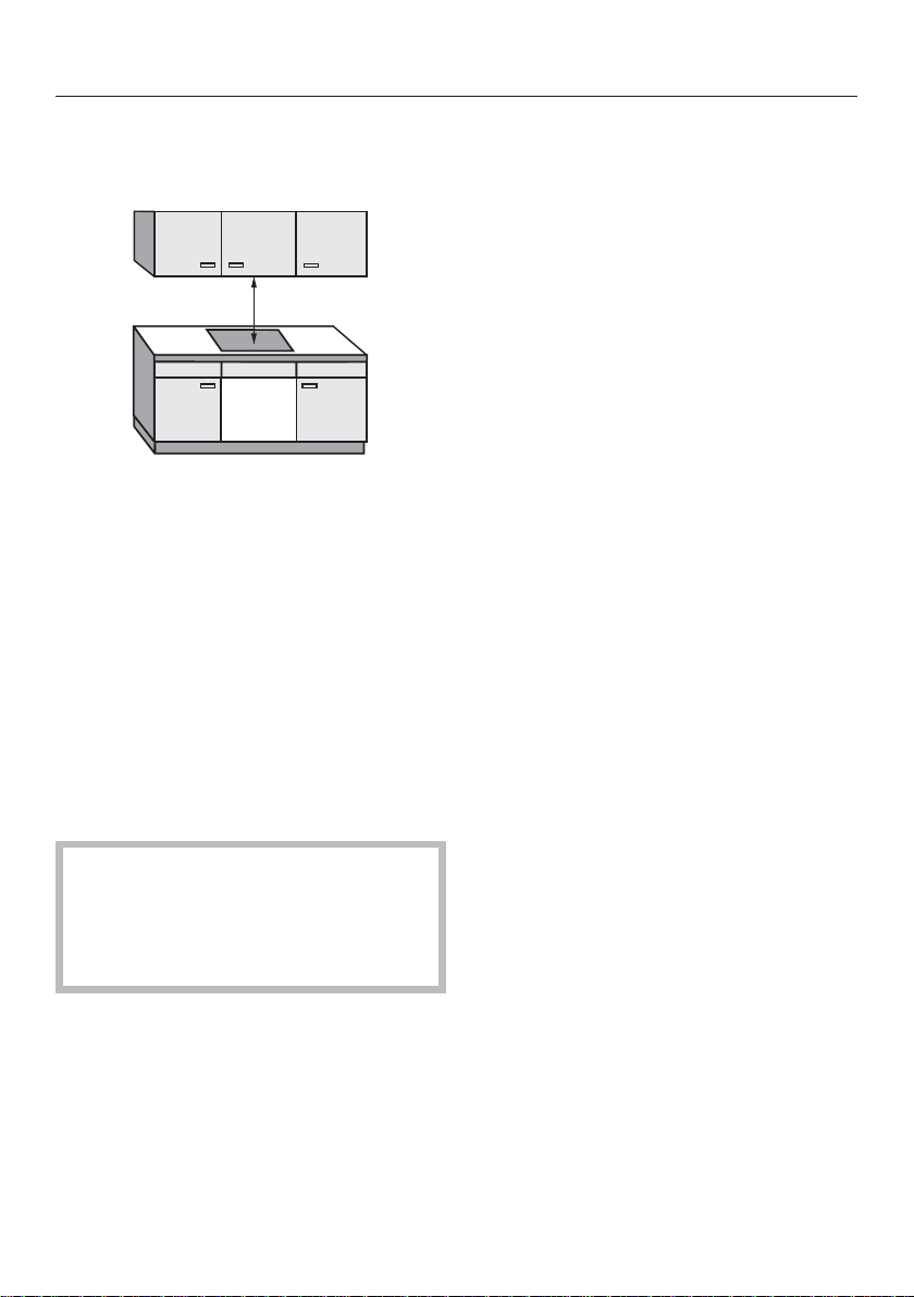
Safety distance above the cooktop
The safety distance specified by the
manufacturer of the rangehood must be
maintained between the cooktop and
the rangehood above it.
If the manufacturer's instructions are
not available for the rangehood, a
minimum safety distance of 600mm
must be maintained.
11274160-02
For any flammable objects, e.g. utensil
rails, wall units etc., a minimum safety
distance of 600mm must be
maintained between these objects and
the highest part of the cooktop below.
When two or more appliances which
have different safety distances are
installed together below a
rangehood, observe the greatest
specified safety distance.
Page 3

*INSTALLATION*
11274160-02
Installation
Safety distances to the sides and
back of the appliance
The minimum distance shown below
must be maintained between the back
edge of the cooktop and a tall unit or
wall.
Ideally the cooktop should be installed
with plenty of space on either side.
There may be a wall at the rear or a tall
unit or wall on one side (right or left),
taking into account the distances
below. On the other side, however, no
tall unit or wall should stand closer than
300mm to the edge of the cooktop.
Before installing the cooktop, check
that the below clearance requirements
are met.
Minimum horizontal distance from the
back edge of the cooktop to a
combustible surface:
50mm.
Minimum horizontal distance from the
right edge of the cooktop to a
combustible surface:
50mm.
Minimum horizontal distance from the
left edge of the cooktop to a
combustible surface:
50mm.
Minimum safety distance underneath
the cooktop
To ensure sufficient ventilation to the
cooktop, a minimum distance must be
left between the underside of the
cooktop and any oven, interim shelf or
drawer.
The minimum gap between the
underside of the cooktop and
- the top edge of an oven: 2mm
- the top edge of an interim shelf:
2mm
- the top edge of a drawer: 5mm
- the base of a drawer: 75mm
Interim shelf
It is not necessary to fit an interim shelf
underneath the cooktop but one may
be fitted if you wish.
Leave a gap of 10mm at the back
between the cabinet and the interim
shelf to accommodate the power
cable.
A gap of 20mm is recommended at the
front between the cabinet and interim
shelf for better ventilation of the
cooktop.
Page 4
*INSTALLATION*
Installation
11274160-02
Installation notes
Surface-mounted installation
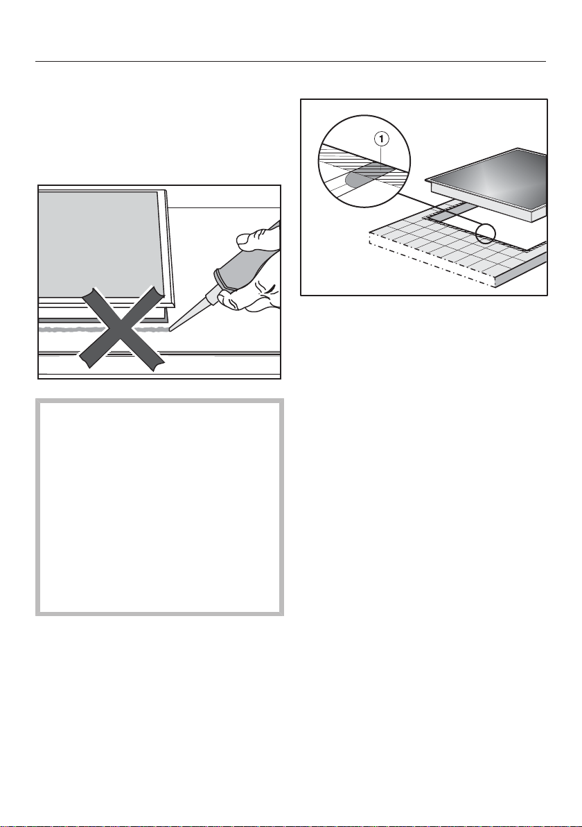
Seal between the cooktop and the
worktop
Damage caused by incorrect
installation.
Using sealant under the cooktop
could result in damage to the
cooktop and the worktop if the
cooktop ever needs to be removed
for servicing.
Do not use sealant between the
cooktop and the worktop.
The sealing strip under the edge of
the cooktop provides a sufficient seal
for the worktop.
Tiled worktop
Grout lines and the hatched area
underneath the cooktop frame must be
smooth and even. If they are not, the
cooktop will not sit flush with the
worktop and the sealing strip
underneath the cooktop will not provide
a good seal between the cooktop and
the worktop.
Page 5
*INSTALLATION*
11274160-02
Installation
Flush-fit installation
Flush-fit installation is only possible in
natural stone (granite, marble), solid
wood and tiled worktops. When using
a worktop made from any other
material, please check first with the
worktop manufacturer that it is
suitable for installing a flush-mounted
cooktop.
The internal width of the base unit
underneath the appliance must be at
least as wide as the inner worktop cutout (see “Installation – Installation
dimensions – Flush”), so that the
cooktop is easily accessible from
underneath after installation and the
bottom half of the casing can be
removed for maintenance. If the
underside of the cooktop is not freely
accessible after installation, any
sealant used to plug the gaps around
the appliance must be removed to
enable the cooktop to be lifted out of
the cut-out should this be necessary.
Natural stone worktops
The cooktop is placed directly in the
cut-out.
Solid wood worktops, tiled worktops,
glass worktops
The cooktop is placed on a wooden
frame inside the cut-out. The frame
must be provided on site and is not
supplied with the appliance.
Sealing strip
Dismantling the cooktop for service
purposes may damage the sealing
strip underneath the edge of the
cooktop.
Always replace the sealing strip
before reinstalling the cooktop.
Page 6

*INSTALLATION*
11274160-02
Installation
Installation dimensions– Surface-mounted
All dimensions in this instruction booklet are given in mm.
KM7678FR
a
Front
b
Mains connection box
The mains connection cable (L = 1,440mm) is supplied loose
Page 7

*INSTALLATION*
KM7678FL,KM7878FL
11274160-02
Installation
a
Front
b
Mains connection box
The mains connection cable (L = 1,440mm) is supplied loose
Page 8

*INSTALLATION*
Installation
KM7697FR
11274160-02
a
Front
b
Mains connection box
The mains connection cable (L = 1,440mm) is supplied loose
Page 9

*INSTALLATION*
KM7697FL,KM7897FL
11274160-02
Installation
a
Front
b
Mains connection box
The mains connection cable (L = 1,440mm) is supplied loose
Page 10

*INSTALLATION*
Installation
11274160-02
Surface-mounted installation
Create the worktop cut-out.
Remember to maintain the minimum
safety distances (see “Installation –
Safety distances”).
Seal the cut surfaces of wooden
worktops with a suitable sealant to
avoid swelling caused by moisture.
The sealant must be heat-resistant.
Make sure the sealant does not
come into contact with the top
surface of the worktop.
Attach the sealing strip provided
underneath the edge of the cooktop.
Do not apply the sealing strip under
tension.
Risk of damage from incorrect
connection.
The electronics of the cooktop may
be damaged if a short-circuit occurs.
The mains connection cable must be
connected to the cooktop by a
qualified electrician.
If the seal does not meet the worktop
correctly on the corners, the corner
radius (≤ R4) can be carefully scribed
to suit.
Connect the cooktop to the electricity
supply (see “Installation – Electrical
connection”).
Check that the cooktop works.
Connect the mains connection cable
by following the instructions in the
wiring diagram on the cooktop (see
“Installation – Electrical connection”).
Feed the mains connection cable
down through the worktop cut-out.
Place the cooktop centrally in the
cut-out. When doing this make sure
that the seal of the appliance sits
flush with the worktop on all sides.
This is important to ensure an
effective seal with the worktop.
Page 11

*INSTALLATION*
11274160-02
Installation dimensions–Flush
All dimensions in this instruction booklet are given in mm.
KM7678FL,KM7878FL
Installation
a
Front
b
Mains connection box
The mains connection cable (L = 1,440mm) is supplied loose
c
Stepped cut-out, natural stone worktop
d
Wooden strip 12mm (not supplied)
Page 12

*INSTALLATION*
Installation
KM7697FL,KM7897FL
11274160-02
a
Front
b
Mains connection box
The mains connection cable (L = 1,440mm) is supplied loose
c
Stepped cut-out, natural stone worktop
d
Wooden strip 12mm (not supplied)
Page 13

*INSTALLATION*
11274160-02
Installation
Flush-fit installation
Create the worktop cut-out.
Remember to maintain the minimum
safety distances (see “Installation –
Safety distances”).
Solid wood, tiled and glass worktops:
Fix a wooden frame 5.5mm below
the top edge of the worktop.
Risk of damage from incorrect
connection.
The electronics of the cooktop may
be damaged if a short-circuit occurs.
The mains connection cable must be
connected to the cooktop by a
qualified electrician.
Connect the mains connection cable
by following the instructions in the
wiring diagram on the cooktop (see
“Installation – Electrical connection”).
Attach the sealing strip provided
underneath the edge of the cooktop.
Do not apply the sealing strip under
tension.
Seal the gap between the cooktop
and worktop with a silicone sealant
that is heat-resistant to at least
160°C.
Damage caused by unsuitable
sealant.
Unsuitable sealant can damage
natural stone.
For natural stone worktops and
natural stone tiles, only use silicone
sealant that is specially formulated
for natural stone. Please follow the
manufacturer's instructions.
Feed the mains connection cable
down through the worktop cut-out.
Centre the cooktop in the cut-out.
The gap between the ceramic surface
and the worktop must be at least
2mm wide. This is required so that
the cooktop can be sealed.
Connect the cooktop to the electricity
supply (see “Installation – Electrical
connection”).
Check that the cooktop works.
Page 14

*INSTALLATION*
Installation
11274160-02
Electrical connection
Risk of damage from incorrect
connection.
Incorrect installation, maintenance
and repairs can be dangerous to
users.
Miele cannot be held liable for
damage or injury caused by incorrect
or unauthorised installation,
maintenance or repair work, or by an
inadequate or faulty on-site earthing
system (e.g. electric shock).
All electrical work must be carried
out by a suitably qualified and
competent electrician, in strict
accordance with current national and
local safety regulations, and any
additional regulations of the local
electricity provider.
After installation, ensure that all
electrical components are shielded
and cannot be accessed by users.
Total power output
See data plate.
Connection data
The connection data is quoted on the
data plate. Please ensure this
information matches the household
mains supply.
Please see the wiring diagrams for
connection.
Residual current device
For extra safety, it is advisable to
protect the appliance with a suitable
residual current device (RCD) with a trip
range of 30 mA.
Disconnecting devices
Connection must be made via a
suitable isolator switch which provides
disconnection on all poles and which
complies with national and local safety
regulations. When switched off there
must be an all-pole contact gap of at
least 3 mm in the isolator switch. The
isolator switch must be easily
accessible after the appliance has been
built in.
Page 15

*INSTALLATION*
L1
200-240 V~
200-240 V~
200-240 V~
ab
cde
-
L2 L3 N
-
L2
b
L1
a cdNe
(L3)
200-240 V~
200-240 V~
aL1bcdNe
-
(L2)
200-240 V~
11274160-02
Installation
Mains connection cable
The cooktop must be connected to the
electrical supply with a special
connection cable, type H 05 VV-F (PVC
insulated) with a suitable diameter.
Please see the wiring diagram for
connection.
See the data plate on the cooktop for
the correct voltage and frequency.
The connection cable comes supplied
with a ferrite sleeve attached. This end
must be fitted to the terminal box of the
cooktop. If using a different connection
cable, with the exception of the earth
conductor, all other single conductors
of the power cable must be fed through
the opening of the ferrite sleeve before
attaching them to the connection
terminals.
Replacing the mains connection
cable
Danger of electric shock!
Incorrect connection to the electricity
supply may result in an electric
shock.
The mains connection cable must
only be replaced in accordance with
current local and national safety
regulations.
When replacing the mains connection
cable, it must be replaced with cable
type H05VV-F by a Miele authorised
service technician or a suitably qualified
and competent electrician in order to
avoid a hazard. These cables are
available from Miele.
Wiring diagram
 Loading...