

Page 1

Operating instructions
Professional
cleaning machine
IR 6002
To avoid the risk of accidents or
damage to the machine it is
essential to read these instructions
before it is installed, commissioned
and used for the first time.
en-GB
M.-Nr. 06 828 452
Page 2

Contents
Description of the machine..........................................5
Areas of application.................................................5
Cleaning process...................................................5
Water recovery.....................................................5
Guide to the machine ..............................................7
Warning and Safety instructions .....................................9
Correct application ...............................................9
Symbols on the machine .........................................13
Opening and closing the door ......................................14
Electric door lock ..................................................14
To open the door with the emergency release ...........................14
Water softener ...................................................15
Setting the water softener ...........................................15
Reactivation display................................................15
Reactivating the water softener .......................................16
Filling the salt container ..........................................16
Position the salt container as follows ................................16
Run the reactivation programme ...................................17
Automatic mobile unit recognition (AWK) (optional) ....................18
Mobile unit coding .................................................18
Mobile unit coding strip ..........................................19
Setting mobile unit coding ........................................19
Areas of application...............................................21
Cover plate ......................................................21
Baskets .........................................................21
Special cleaning applications ........................................21
Cleaning programmes ..............................................22
Water connection spring adapter .....................................23
Height adjustable top basket.........................................23
Electronics .......................................................24
Printed circuit boards ............................................24
Fluxing agents and soldering paste ................................24
Soldering frames ................................................25
Metal cleaning ....................................................26
Glass cleaning ....................................................27
Baskets and inserts .............................................27
Particle decontamination ............................................28
2
Page 3

Contents
Chemical processes and technology.................................29
Dispensing liquid chemical agents ..................................34
Preparing the dispensing system .....................................34
Fill the containers with the relevant agent ............................35
Venting the dispensing system .......................................36
Dispensing system maintenance......................................36
External Dispensing systems.........................................36
Operation .......................................................37
Switching on .....................................................37
Changing the operating level ........................................37
Starting a programme ..............................................37
Programme sequence ..............................................39
Switching off .....................................................39
Cancelling a programme ............................................39
Interrupting a programme ...........................................40
Data transfer.....................................................41
Maintenance .....................................................42
Maintenance and care..............................................42
Routine checks ...................................................42
Maintenance .....................................................43
Cleaning the filters in the wash cabinet.................................43
Cleaning the coarse filter .........................................43
Cleaning the flat and micro-fine filters ...............................43
Cleaning the spray arms ............................................44
Cleaning the control panel...........................................45
Cleaning the front of the machine .....................................45
Cleaning the wash cabinet ..........................................45
Cleaning the door seals.............................................45
Mobile units, baskets and inserts .....................................46
Drying unit (TA) ...................................................47
Changing the coarse filter ........................................47
Exchanging the HEPA filter........................................48
Problem solving .................................................49
Thermal cut-out ...................................................49
Cleaning the filters in the water inlet ...................................50
After sales service ................................................51
3
Page 4

Contents
Installation ......................................................52
Electrical connection .............................................53
Plumbing........................................................54
Connection to the water inlet .........................................54
Drainage ........................................................56
Vent at the rear ...................................................56
Technical data ...................................................57
Disposal of your old machine.......................................58
4
Page 5

Description of the machine
Areas of application
This professional cleaning machine is
particularly suitable for use in high-tech
industrial production plants where very
high reproducible standards of
cleaning are required for complex
items.
Areas of application include:
Electronic components such as
–
printed circuit boards and soldering
frames,
Metal cleaning,
–
– Glassware cleaning,
– Decontamination of boxes and trays.
Cleaning process
This machine uses the fresh water
principle. The batch time for cleaning,
rinsing etc. is between 20 and 60
minutes. Drying takes place in an
integrated drying unit. Drying times will
vary depending on the heat retention
properties of the items being
processed as well as the amount of
contact water left on them after
cleaning. An additional drying time of
between 15 - 45 minutes should be
calculated.
This machine can be equipped with
baskets and inserts to suit the
application it will be used for.
Application specific programmes can
also be added.
Each application requires its own
cleaning programme. These are not
supplied as standard.
Water recovery
The IR 6002 is supplied with a two-part
drainage system and a pump for
recovering process water from the
machine for re-use. This water must be
stored in a recycling tank (not supplied)
situated next to the professional
cleaning machine.
This machine, together with the
recycling tank as applicable, can be
used as follows:
1. Fresh water system:
The whole process is carried out with
fresh water. Once used the water is
drained into the mains drainage
system, or into a special water disposal
unit.
2. Recyling the rinse water:
Water from the last two rinses, for
example, is recovered and used for the
cleaning and neutralising stages of the
next batch. Used water from the
cleaning and neutralising stages is then
drained into the mains drainage system
or into a special water recycling unit.
3. Recyling the cleaning water:
Used water from the cleaning stage is
recovered and used for the cleaning
stage of the next batch. Used water
from the remaining rinse stages is then
drained into the mains drainage system
or into a special water recycling unit.
5
Page 6
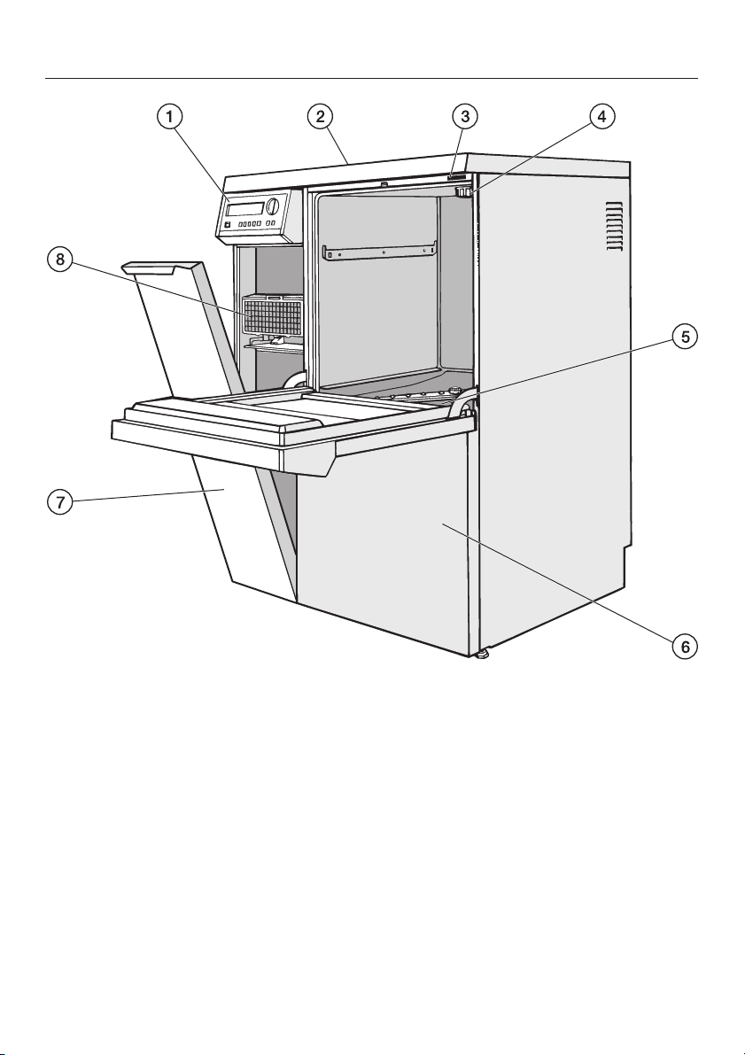
Description of the machine
a Electronic controls
b Serial interface, at the back of the
machine (top left behind the cover
panel)
c Test point for validation
d Salt reservoir connection point
(for the water softener)
e Filter combination
f Service panel
6
g Service panel
h Drying unit (TA)
Page 7
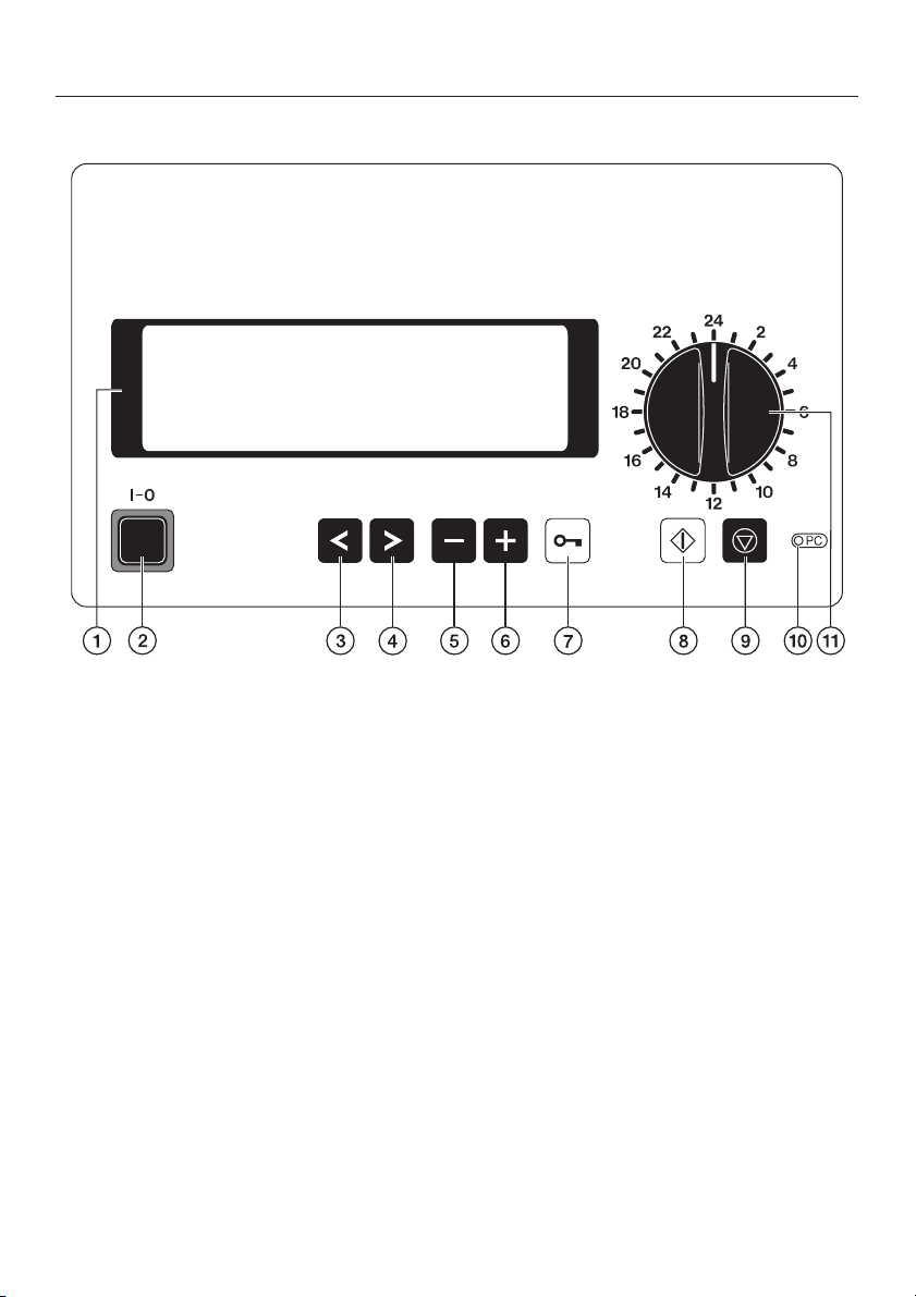
Electronic controls
Guide to the machine
a Display
with screen saver;
i.e. background lighting switches off
automatically after 15 mins.
Press any button to switch the
display back on again.
b On/Off button (I-0)
c Cursor button: left 1
Moves the cursor to the left:
- to the previous menu point
- to the previous parameter
- to the previous input position
d Cursor button: right 2
Moves the cursor to the right:
- to the next menu point
- to the next parameter
- to the next input position
e Minus button 3
– Selects programmes from position
24 upwards
– Scrolls back page by page in
menus
– Is used for entering numbers and
letters
– Alters pre-settings e.g. service
parameters
f Plus button 4
– Selects programmes from position
24 upwards
– Scrolls forward page by page in
menus
– Is used for entering numbers and
letters
– Alters pre-settings e.g. service
parameters
g Door switch 5
7
Page 8

Guide to the machine
h Start button 6
– Starts programmes
– Activates input mode
– Confirms activated values and
settings
– Confirms menu points for entry
into the relevant sub-menu
i Stop button 7
– Cancels a programme
– Exits from input screen without
saving
– Exits from menu screen
j Service interface 8
kProgramme selector
Selects programme places 1-23
8
Page 9

This machine complies with all
current safety requirements.
Inappropriate use can, however,
lead to personal injury and damage
to property.
To avoid the risk of accidents and
damage to the machine, please
read these instructions carefully
before starting to use it. Keep these
instructions in a safe place for
reference, and pass them on to any
future user.
Correct application
Warning and Safety instructions
Please pay attention to the following
notes to avoid injury and damage.
This machine should be installed,
~
commissioned and then maintained by
a Miele authorised and trained service
technician or other suitably qualified
and competent approved person.
Repairs and other work by unqualified
persons could be dangerous. The
manufacturer cannot be held liable for
unauthorised work.
Do not install the machine in an area
~
where there is any danger of explosion
or of freezing conditions.
This machine is designed for use as
~
described in these operating
instructions only. Alterations or
conversions to the machine, or using it
for purposes other than those for which
it is designed, are not permitted and
could be dangerous.
The manufacturer cannot be held liable
for damage caused by improper or
incorrect use or operation.
This machine is intended for land
~
based stationary, indoor use only. It
must not be installed in mobile sites
such as ships or military containers etc.
The electrical safety of this machine
~
can only be guaranteed if connected to
a correctly installed on-site earthing
system which complies with local and
national safety regulations. It is most
important that this basic safety
requirement is present and regularly
tested, and where there is any doubt,
the on-site wiring system should be
inspected by a qualified electrician.
The manufacturer cannot be held liable
for damage or injury caused by the lack
of or inadequacy of an effective
earthing system (e.g. electric shock).
A damaged or leaking machine is
~
dangerous. Disconnect the machine
from the mains immediately and call the
Miele Service Department.
Personnel operating the machine
~
should be trained regularly. Untrained
personnel must not be allowed access
to the machine or its controls.
9
Page 10

Warning and Safety instructions
Take care when handling chemical
~
agents such as cleaning agent,
neutralising agent, rinsing agent etc.
These may contain irritant or corrosive
ingredients.
Please follow the manufacturer's safety
instructions. Wear protective gloves
and goggles. With all chemical agents,
the manufacturer's safety instructions
and safety data sheets must be
observed.
The machine is designed for
~
operation with water and recommended
additive chemical agents only. Organic
solvents and flammable liquid agents
must not be used in this machine.
These could cause an explosion,
damage rubber and plastic
components in the machine, and cause
liquids to leak out of the machine.
The water in the cabinet must not be
~
used as drinking water.
Do not sit or lean on an open door.
~
The machine could tip up and be
damaged or cause an injury.
Be careful when sorting items with
~
sharp pointed ends and positioning
them in the machine that you do not
hurt yourself or create a danger for
others. Sharp knives etc. should be
placed in baskets with the pointed ends
facing downwards.
When using this machine in the
~
higher temperature ranges, be
especially careful not to scald or burn
yourself or come into contact with
irritant substances when opening the
door. Where disinfecting agents are
used there is a danger of inhaling toxic
vapours.
Where there is a risk of toxic or
~
chemical substances occuring in the
suds solution (e.g. aldehyde in the
disinfecting agent), it is essential to
regularly check door seals and make
sure that the steam condensor is
functioning correctly.
Opening the machine door during a
programme interruption carries
particular risks in such circumstances.
Should personnel accidentally come
~
into contact with toxic vapours or
chemical agents, follow the emergency
instructions given in the manufacturer's
safety data sheets.
Mobile units, modules, inserts and
~
the load must be allowed to cool down
before unloading the machine. Any
water remaining in containers could still
be very hot. Empty them into the wash
cabinet before taking them out.
After using the hot air drying unit,
~
open the door to allow the everything in
the cabinet from the load itself to the
mobile units, modules and inserts to
cool down.
10
Do not touch the heating elements if
~
you open the door during or directly
after the end of a programme; you
could burn yourself. They remain hot for
some time after the end of the
programme.
Page 11

Warning and Safety instructions
Do not clean the machine or near
~
vicinity with a water hose or a pressure
washer.
The machine must be disconnected
~
from the mains electricity supply before
any maintenance or repair work is
carried out. Do not reconnect it until the
maintenance or repair work has been
successfully completed.
The following points should be
observed to assist in maintaining
quality standards, to protect users,
and to avoid damage to the machine
and items being cleaned.
Chemical agents could, under
~
certain conditions, cause damage to
the machine. Please only use agents
recommended by Miele. In the event of
any damage or material deterioration
please contact your Miele application
specialist.
Pre-treatments with cleaning or
~
disinfecting agents can create foam, as
can certain types of soiling and
chemical agents. Foam can have an
adverse effect on the cleaning process.
Foam must not be able to escape
~
from the wash cabinet. It would hinder
the correct functioning of the machine.
Check the process used regularly to
~
monitor foaming levels.
To avoid the risk of damage to the
~
machine and any accessories used
with it caused by chemical agents,
soiling and any reaction between the
two, please read the notes in "Chemical
processes and technology".
Where a chemical additive is
~
recommended on technical application
grounds (e.g. a cleaning agent), this
does not imply that the manufacturer of
the machine accepts liability for the
effect of the chemical on the items
being cleaned.
Please be aware that changes in
formulation, storage conditions etc.
which may not be publicised by the
chemical manufacturer, can have a
negative effect on the cleaning result.
When using cleaning agents and
~
specialised products it is essential that
the manufacturer's instructions are
followed. Chemicals must only be used
for the purpose they are designed for
and in the situation specified, to the
exclusion of other chemicals, to avoid
such dangers as chemical reactions
(e.g. oxyhydrogen reaction) and
material damage.
In critical applications where very
~
stringent requirements have to be met,
it is strongly recommended that all the
relevant factors for the process, such
as chemical agents, water quality etc.
are discussed with the Miele
Application Technology specialists.
11
Page 12

Warning and Safety instructions
If cleaning and rinsing results are
~
subject to particularly stringent
requirements (e.g. chemical analysis,
specialised industrial processes etc.), a
regular quality control test must be
carried out by the user to ensure that
the required standards of cleanliness
are being achieved.
Mobile units, modules and inserts
~
should only be used for the purpose
they are designed for.
Empty any containers or utensils
~
before arranging them in the machine.
Do not allow any remains of acids or
~
solvents, and in particular hydrochloric
acid or chloride solutions, to get into
the wash cabinet. Similarly avoid any
materials with a corrosive effect. The
presence in compounds of any solvents
should be minimal (especially those in
hazard class A1).
Please ensure that any water
~
drained into the public mains drainage
system complies with all local and
national water regulations. To prevent
pollution to the waterways please
ensure that accepted tolerance levels
are adhered to.
Do not process items in this
~
machine if they have, for example,
filings or metal shavings on them.
Depending on the type and shape of
filings, shavings etc. there is a risk of
them causing damage to the circulation
pump and also of causing contact
corrosion.
Ensure that solutions or steam
~
containing hydrochloric acid do not
come into contact with the steel outer
casing of the machine, to avoid any
corrosion damage.
After carrying out any work on the
~
mains water system, the water supply
system to the machine must be vented.
Otherwise, components of the machine
may become damaged.
12
Please follow the advice on
~
installation in these instructions and the
separate Installation Instructions.
Page 13
Warning and Safety instructions
Using accessories
Only use genuine Miele original
~
accessories with this machine and only
use them for the purposes they are
designed for. Consult Miele on the type
and application of such equipment.
Only use Miele mobile units, baskets
~
and inserts in this machine. Using
accessories, mobile units and inserts
made by other manufacturers, or
making modifications to Miele
accessories, can result in
unsatisfactory cleaning results, for
which Miele cannot be held liable. Any
resultant damage would also invalidate
the machine guarantee.
Only use chemical agents which
~
have been approved by their
manufacturer for use in the application
you are using. The chemical agent
manufacturer is responsible for any
negative influences on the material the
load is made from and for any damage
they may cause to the machine.
Disposing of your old machine
Please note that the machine may
~
have contamination from dangerous,
toxic or infectious substances in it and
must be decontaminated before
disposal.
For environmental and safety reasons
ensure the machine is completely
drained of any residual water and
process chemicals. Observe safety
regulations and wear safety goggles
and gloves.
Make the door lock inoperable, so that
children cannot accidentally shut
themselves in. Then make appropriate
arrangements for its safe disposal.
For tank system machines ensure that
any water is emptied out of the tank.
The manufacturer cannot be held
liable for damage caused by
non-compliance with these Warning
and Safety instructions.
Symbols on the machine
Warning:
Observe the operating
instructions.
Warning:
Danger of electric shock.
13
Page 14
Opening and closing the door
Electric door lock
This machine is equipped with an
electric door lock.
The door can only be opened when:
the electricity supply to the machine
–
is switched on,
the master switch I-0 is pressed in,
–
and
a cleaning programme is not in
–
progress.
To open the door
^ Press the 5 door button, and holding
onto the door grip open the door.
Do not touch the heating
,
elements if you open the door during
or directly after the end of a
programme: you could burn
yourself. They remain hot for some
time after the end of the programme.
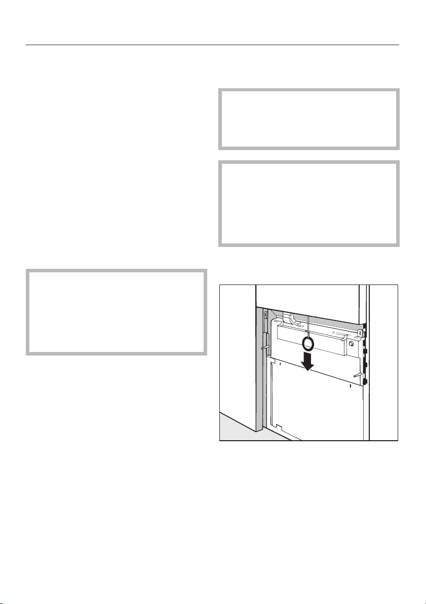
To open the door with the
emergency release
The emergency release should
,
only be used when the door cannot
be opened normally, e.g. in the
event of a power failure.
If there is a lot of hot water in the
,
wash cabinet when the programme
is interrupted and the door is then
closed quickly, hot water can
escape.
Danger of burning or scalding.
^ Switch the machine off with the I-0
button.
To close the door
^
Lift the door upwards and push until
it clicks shut.
14
^
The emergency release cable is
located at the bottom of the machine
behind the service panel. Pull it
downwards to open the door.
Page 15
In order to achieve good cleaning
results, the machine needs to operate
with soft water. Hard water results in the
build-up of calcium deposits on the
load and inside the wash cabinet.
Mains water with a hardness level
higher than 0.7 mmol/l (4 °d – German
scale) needs to be softened. This takes
place automatically in the integrated
water softener.
The water softener requires
–
reactivation salt.
The machine must be programmed
–
to correspond to the water hardness
in your area.
Water softener
Enter your water hardness level here:
°dH or mmol/l
Setting the water softener
When the machine is first
commissioned the Miele service
technician has to set the machine for
your local water hardness level (see
Programme manual, Operating
information/Reactivation).
– Your local water authority will be able
to advise you on the water hardness
in your area.
The water softener unit is set at the
factory for a water hardness level of
19 °dH (3.4 mmol/l).
If the water supply is harder or softer
than this (including below 0.7 mmol/l
or 4 °dH) the factory setting will
need to be reprogrammed via the
electronic controls.
For fluctuating levels, e.g.8-17°dH
(1.4 - 3.1 mmol/l), set the water softener
to the highest setting; in this example,
to 17 °dH (3.1 mmol/l).
The built-in water softener has
settings from 1 °dH - 60 °dH (0.2 -
10.8 mmol/l).
For future servicing it is useful to make
a note of your water hardness level.
Reactivation display
After a certain number of cycles the
message REACTIVATION will appear in
the display to warn you that the water
softener is depleted and cannot supply
any more softened water. As soon as
the programme has finished
reactivation salt will need to be
replenished.
If this cannot be done immediately, and
further cleaning cycles have been
carried out, the reactivation process will
need to be carried out twice in
succession.
15
Page 16
Water softener
Reactivating the water softener
Please only use special coarse grained
reactivation salt with granules of
approx. 1-4 mm. Do not use other types
of salt, e.g. table salt, agricultural or
gritting salt. These could contain
components which are insoluble in
water which could result in damage to
the water softener.
The salt container holds approx. 2 kg of
salt.
If only fine grained reactivation salt
is available please consult the Miele
Spare Parts Department for advice.
Salt with granules ü 4 mm must not
be used in this machine.
,
Inadvertently filling the salt
reservoir with cleaning agent can
cause serious damage to the water
softener and damage the filter insert,
and cause pressure to build-up in
the salt container. To avoid the risk
of injury please exercise caution
when removing the salt container as
there may be irritant alkaline
solutions present.
Before filling the salt container make
sure that you have picked up the
right packet of reactivation salt.
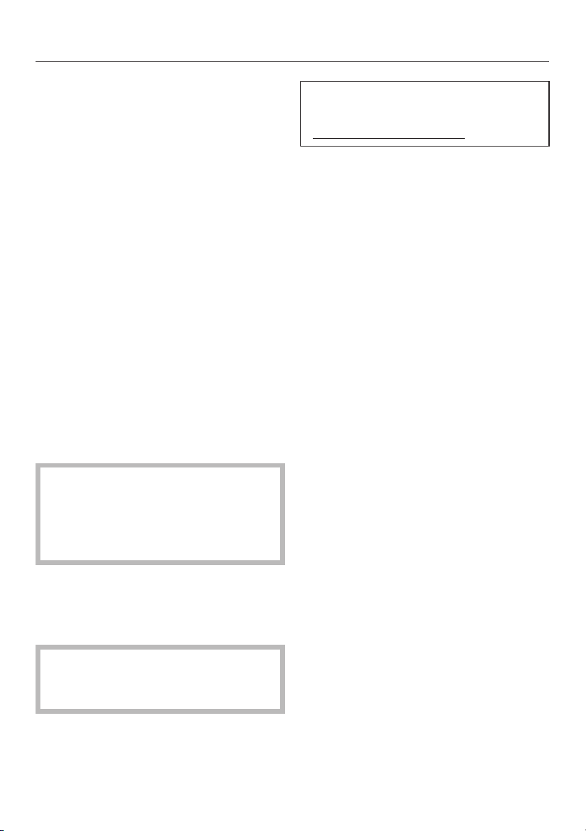
Filling the salt container
Unscrew the filter insert from the salt
^
container and remove.
^ Fill the salt container with reactivation
salt and screw the filter insert back in
place.
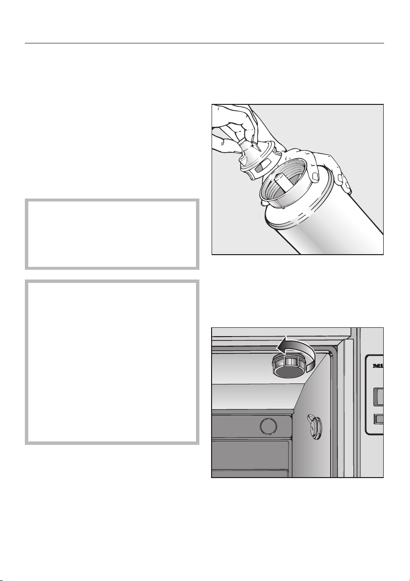
Position the salt container as follows
16
^
Remove any mobile units from the
cabinet.
^
Unscrew the plastic cap situated in
the top right-hand side of the cabinet.
Page 17
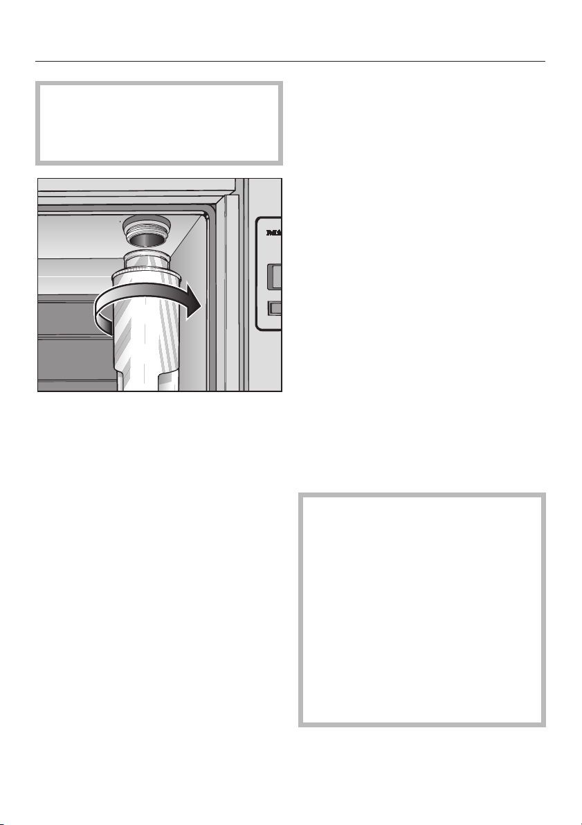
There will be a small amount of
,
residual water in the cap. Take care
as it may be hot from the previous
programme.
^ Screw the salt container firmly onto
the socket.
Water softener
Then:
Switch off the machine.
^
Carefully unscrew the salt container,
^
making sure any water pressure still
remaining can depressurise. Do not
use force!
If the container will not come off
manually please contact the Miele
Service Department.
Replace the cap.
^
Select and start the COLD WASH
^
programme to flush out any excess
salt from the softener unit and from
the cabinet.
^ Push the mobile unit back into the
cabinet.
^ Turn off the stopcocks.
^ Empty the salt container. Do not
empty it into the wash cabinet.
Run the reactivation programme
^ Close the door.
^
Open the stopcocks.
^
Select the REACTIVATION
programme.
The programme will run automatically.
^ Rinse the salt container and filter
insert with clean water.
The water pressure (flow pressure at
the take off point) must be at least
150 kPa (1.5 bar) for cold and hot
water.
If it is below150 kPa (1.5 bar) or if it
fluctuates a lot, the water softener
will not work properly. After
reactivation, salt remains may still be
found in the salt container.
To use up salt remains and to rinse
out the water softener, the
REACTIVATION programme must be
carried out again.
17
Page 18

Automatic mobile unit recognition (AWK) (optional)
In operating level C the automatic
mobile unit recognition system (AWK)
allocates programme places from 1 15 to mobile units with the correct
coding.
The unit coding (on the mobile unit) and
the programme place with the
corresponding programme (in the
electronic control unit) have to match
each other.
To do this:
Each mobile unit must be coded
^
before being used for the first time
(see "Coding the mobile unit"), and
^ The programme for which the mobile
unit is coded must be allocated to t
^ he correct programme place.
See "System function - Selector switch
organisation" in the Programming
manual for information on how to
change programme positions.
,
Before starting a programme it is
absolutely essential that you check
that the programme shown in the
display is the correct one for the
mobile unit being used.
Otherwise inadequate cleaning or
disinfection could be the result.
Please make sure, that the places
assigned for the programmes using
Automatic mobile unit recognition
are not changed around arbitrarily.
Mobile unit coding
The automatic mobile unit recognition
feature assigns a programme place to
a mobile unit. The mobile units must be
coded with a magnetic strip (via a Bit
combination).
In operating level C, the only
programme available for a coded
mobile unit is the one assigned to the
corresponding programme place.
After a coded mobile unit has been put
into the machine and the door closed,
the automatic mobile unit recognition
system will select the allocated
programme (as long as there are no
residues or particles on the magnetic
strip).
Make sure that there are no
,
small metallic objects or instrument
parts attracted to the magnetic strip,
in particular to the underside of it.
Any metallic objects on the strip can
result in the coding being incorrectly
read.
Press 6 to start the programme.
18
Page 19

Automatic mobile unit recognition (AWK) (optional)
Coding is effected through 5 Bits:
Bits 1 to 4 define the mobile unit
–
code,
Bit 5 serves as a control (Parity Bit).
–
Mobile unit coding strip
15 different codes can be set. They are
assigned to programme places 1 to 15.
Under "System function, Selector switch
organisation" the matching
programmes have to be put into the
first 15 programme places.
Programme
place
10
11
12
13
14
15
Bit 1 Bit 2 Bit 3 Bit 4 Bit 5
0
1
2
3
4
5
6
7
8
9
0
0
I
I
0
I
I
0
0
0
I
I
0
I
I
0
0
0
I
I
0
I
I
0
0
0
I
I
0
I
I
Parity
Bit
0
0
0
0
0
0
I
I
I
I
0
0
0
0
I
I
I
I
I
0
I
0
0
0
I
0
0
0
0
0
I
0
I
I
0
I
0
I
I
I
0
I
I
I
I
I
0
I
The coded total must be an even
number.
If the coded total gives an odd number
the message CHECK MOBILE UNIT
RECOGNITION appears.
If the mobile unit total equals 0, the
message NO MOBILE UNIT
RECOGNITION will appear. In neither
case can the programme be started,
The mobile unit recognition function
must be re-set.
Setting mobile unit coding
To set or alter the coding of a mobile
unit with automatic recognition (AWK),
proceed as follows:
^
Unscrew the track with AWK (using
an allen key) and remove from the
retainer.
19
Page 20

Automatic mobile unit recognition (AWK) (optional)
Remove the magnetic strip from the
^
track.
Put the magnetic strip back in the
^
track.
The magnetic strip must be placed
in the track such that the Bit coding
set out in the chart is visible through
the round windows in the track.
^
Set the programme place coding.
20
^
Place the track in the holder in the
mobile unit and screw firmly in place.
The magnetic strip must have grey
magnets.
Page 21

Areas of application
Cover plate
The machine is supplied with a baffle
fitted in front of the hot air outlet in the
rear wall of the wash cabinet.
This baffle has to be dismantled if
mobile units and baskets are used
which have a drying unit connection on
them.
^ Loosen both screws on the baffle.
Baskets
This machine can be fitted with wide
variety of baskets. There are too many
to describe them all here. Please
contact your Miele application
specialist for details of suitable baskets
and inserts for your requirements, or to
discuss the possiblity of having custom
built ones for your particular
application.
Special cleaning applications
It is possible to test particular cleaning
requirements. The machine may then
be used for other applications. Many
users carry out their own test washes.
Should the use of the machine change,
then the cleaning programme can also
be adapted. This applies in particular to
the cleaning agents used, the type of
load, and the type of soiling and
material from which the items are
made.
^ Take the baffle off.
21
Page 22

Areas of application
Cleaning programmes
The machine is supplied without
programmes. When creating
programmes account has to be taken
of the plumbing connections and any
buffer or recyling tank. Consideration
also has be taken of process chemicals
and any physical or chemical
properties of the items being cleaned
and the type of soiling being handled.
The following pages give some tips on
particular problems and ways of
dealing with them.
If you have any questions please
contact the following:
– The Miele Service Department
– Your Miele application specialist
– Your Miele Dealer
Before starting a programme you
should carry out a visual check on
the following:
Is everything correctly
–
loaded/connected for cleaning?
Are the spray arms clean and do
–
they rotate freely?
Are the filters clean? Remove any
–
coarse soiling and clean them
properly if necessary.
Is the adapter connecting the water
–
supply to the spray arms/jets
correctly connected?
– Are all chemical containers filled
sufficiently?
22
Page 23

Areas of application
Water connection spring
adapter
Make sure that the water connection
spring adapter engages correctly when
a basket or injector unit is inserted in
the machine. It must be 4-5 mm higher
than the water connection inlet in the
machine.
If it is not, adjust the adapter
accordingly.
^
Loosen lock ring a.
^
Push up adapter b.
^
Tighten lock ring c.
Height adjustable top basket
The top basket can be adjusted above
and below the middle position by 2 cm.
Depending on the position of the top
basket and the inserts used, the
baskets can accommodate vessels and
instruments of the following heights:
Example: Top basket O 188/1 and
bottom basket U 874/1 without
inserts:
Top basket
position
Top max. 15.5 max. 28.5
Middle max. 17.5 max. 26.5
Bottom max. 19.5 max. 24.5
The height available in the right
hand side of the top basket is limited
by the salt reservoir connection
point.
To adjust the top basket:
^
Pull out the top basket until a
resistance is felt; lift from the runners
and remove.
Top basket
height (cm)
Bottom
basket
height (cm)
^
Unscrew the roller bearings on both
sides of the basket with a suitable
spanner and reposition as required.
23
Page 24

Areas of application
Electronics
Depending on the soldering process
used and the application the products
are to be used for soldering frames
used in the production of electronic
components and printed circuit boards
can be cleaned in this machine.
Printed circuit boards
Resin or colophonium coated circuit
boards can be cleaned in this machine.
The results will be influenced by the
type of fluxing agent used. Please seek
the advice of your application specialist
if required. A tenside additive is
required for cleaning (0.5 - 0.7 % at
65 - 75 °C, process 1 or 2, see
"Description of the machine - Water
recovery") or a special cleaning agent
(20% at 50 °C, process 3, see
"Description of the machine - Water
recovery"). If the rinse water or the
special cleaning agent is to be re-used
a buffer or recycling tank is required.
Fully demineralised water is required
for the rinse.
Fluxing agents and soldering paste
Batch times for cleaning are approx.
30 - 40 min, and approx. 30 - 50 min for
drying, depending on the complexity
and quantity of items being processed.
The special baskets for circuit boards,
upper basket O 500 and bottom basket
U 500 are made from plastic coated
stainless steel. Each is designed to
process 73 europa size circuit boards
per batch.
Upper basket O 500
Residues from the soldering process
are water soluble and must be
removed. The cleaning process then
takes place in water only.
24
Page 25

Bottom basket U 500
Large quantities of small boards can be
processed using inserts such as the
E 402 or E 403 in conjunction with an
E 439. Lightweight or sensitive circuit
boards should be protected with a cover
net or grille.
Areas of application
Carrying out the final rinse on
aluminium soldering frames with fully
demeralised water will help to prevent
any material damage that might be
caused by the quality of the mains
water.
Example: 8 soldering frames approx.
475 mm x 430 mm x 45 - 50 mm (length
x width x thickness) can be cleaned
and dried in this machine in a batch
time of 30 minutes, if the machine is
connected to a 65 °C hot water supply.
Loading example:
Bottom basket U 874 with insert E 500
Soldering frames
Depending on the type of soiling (adipic
acid, colophonium etc.) cleaning should
be carried out using an alkaline cleaning
agent (0.3 - 0.5% at 50 - 75 °C, process
1 or 2, see "Description of the machine Water recovery") or a special cleaning
agent (1 - 3% at 50 - 75 °C, process 3,
see "Description of the machine - Water
recovery"). If the rinse water or the
special cleaning agent is to be re-used
a buffer or recycling tank is required.
Depending on the type of material used
to manufacture the soldering frames it
may be necessary to use an acidic
neutralising agent (0.1 - 0.2%) or a
rinsing agent (0.05 - 0.1%).
Insert E 500
25
Page 26

Areas of application
Metal cleaning
This machine can be used to degrease
and remove any dust and lapping
abrasives from metal components at
the end of the manufacturing process
or before they are lacquered or
galvanised.
Process 1 and 2 (see "Description of
the machine - Water recovery") are
frequently used for this where the items
are only lightly soiled with residues
(0.5-1.0% cleaning agent at 60-80 °C).
Process 3 (see "Description of the
machine - Water recovery") is frequently
used for this where the items are
heavily soiled with residues (1.0-3.0%
cleaning agent at 60-80 °C). If the rinse
water or the special cleaning agent is to
be re-used a buffer or recycling tank is
required.
The cleaning agent and process used
will depend on the iron, steel and
non-ferrous heavy metal content. With
lapping agents a test wash should be
carried out to ascertain cleaning levels.
Make sure that metal shavings
,
(from drilling, cutting etc) cannot get
into the wash cabinet. This is
particularly important with corrosive
iron materials.
The O 188 upper basket in conjunction
with the U 874 bottom basket are
recommended as standard baskets for
this machine, or the 4 level E 439 for
processing small components. Various
mesh trays and inserts are available for
processing very small items. The mesh
trays and inserts can be placed in
O 188/U 874 or E 439.
Depending on the material and rinse
results it is often necessary to carry out
a final rinse with fully demineralised
water.
26
Page 27

Glass cleaning
Technical and optical glassware can be
processed in this machine to remove
grease, dust and lapping abrasives
and to ensure a residue free final rinse.
A residue-free final result will depend
on the quality of the water used.
Technical advice should be sought
regarding the processing of very
sensitive glassware and fine grade
lapping abrasives.
Process 1 and 2 (see "Description of
the machine - Water recovery") are
frequently used for glassware cleaning
(0.5-1.0% cleaning agent at 60-80 °C).
If the rinse water is to be re-used a
buffer or recycling tank is required.
Baskets and inserts
Small glass lenses can be cleaned in
the machine using baskets O 188/U
874 and inserts E 402/403. For larger
glass lenses inserts E 118 and E 136
should be used. Small lenses can also
be processed using an E 403 in an
E 439.
Areas of application
Insert E 118
27
Page 28

Areas of application
Particle decontamination
This machine is particularly suitable for
particle decontamination of chip boxes,
wafer trays, semi-finished products,
assembly trays and computer parts.
Cleaning takes place using a water
based process only, using a very small
amount of special cleaning agent and
without the addition of solvents. The
cleaning process for this application
takes place using the highest grade
water only.
Chip boxes, wafer trays etc. are
cleaned using process 1 only
(see"Description of the machine Cleaning process").
28
Page 29

Chemical processes and technology
General notes
Problem How to resolve it
If elastomers (seals and hoses) and
plastics in the machine suffer damage,
this can cause swelling, shrinkage,
hardening and brittleness in materials
and cause cracks to occur in them.
They will then not function correctly.
This usually takes the form of them not
being water-tight.
Heavy foaming during a programme
affects cleaning and rinsing results.
Foam escaping from the wash cabinet
can cause damage to the machine.
Cleaning processes cannot be
regulated and validated where there
has been a build-up of foam..
Corrosion to stainless steel in the wash
cabinet and to accessories can give
them a different appearance:
– rust (red marks / discolouration),
– black marks / discolouration,
– white marks / discolouration (etched
surface).
Corrosive pitting can lead to the
machine not being water-tight.
Depending on application, corrosion
can influence cleaning and rinsing
results (laboratory analysis) or cause
corrosion to stainless steel items in the
cabinet.
Establish the cause of the damage
–
and put it right.
See information regarding "Chemical
agents", "Soiling" and "Reaction between
chemical agents and soiling".
Establish the cause of the foam and
–
put it right.
Check the process used regularly to
–
monitor foaming levels.
See information regarding "Chemical
agents", "Soiling" and "Reaction between
chemical agents and soiling".
– Establish the cause of the corrosion
and put it right.
See information regarding "Chemical
agents", "Soiling" and "Reaction between
chemical agents and soiling".
29
Page 30

Chemical processes and technology
Chemical agents
Problem How to resolve it
The ingredients in chemical agents
have a strong influence on the longevity
and functionality (throughput) of the
dispensing system. The dispensing
system (hoses and pumps) should be
set up for a particular type of chemical
agent.
General types:
alkaline to pH neutral products,
–
acidic to pH neutral products,
–
hydrogen peroxide.
–
Chemical agents can damage
elastomers and plastics in the machine
and accessories.
The following oxidising chemical agents
can damage elastomers (hoses and
seals) and plastics in the machine:
– nitric acid,
– peracetic acid,
–
products contain active chlorine.
Use Miele approved chemical agents
–
in this machine.
Carry out a regular visual check of
–
the dispensing system for any
damage.
Check the flow rate of the dispensing
–
system regularly.
– Use Miele approved chemical agents
in this machine.
– Carry out a regular visual check of
any accessible elastomers and
plastics for damage.
The wash temperature should be limited
to:
– 50 °C with nitric acid,
– 35 °C with peracetic acid,
–
80 °C with products containing active
chlorine.
The following chemical agents can
release large amounts of oxygen:
–
hydrogen peroxide,
–
peracetic acid.
30
–
Only use approved processes such
as OXIVARIO or OXIVARIO PLUS.
–
The wash temperature must be less
than 70 °C when using hydrogen
peroxide.
–
Please contact Miele Service or your
Miele Application Professional for
advice.
Page 31

Chemical processes and technology
Chemical agents
Problem How to resolve it
The following chemical agents can
cause large amounts of foam to build
up:
Cleaning agents and rinsing agents
–
containing tensides,
emulsifiers.
–
Foam can occur:
in the programme block in which the
–
chemical agent is dispensed,
in the following programme block if it
–
has been spilt,
– in the following programme with
rinsing agent if it has been spilt.
De-foaming agents, especially silicone
based ones can cause the following:
– deposits to build up in the cabinet,
– deposits to build up on the load,
– damage to elastomers and plastics in
the machine,
– damage to certain plastics (e.g.
polycarbonate and plexiglass) in the
load being processed.
Process parameters in the wash
–
programme, such as dispensing
temperature, dosage concentration
etc. must be set to ensure the whole
process is foam free or very low
foaming.
Please observe chemical agent
–
manufacturer's instructions.
– De-foaming agents should be used in
exceptional cases only, for instance
when absolutely essential for the
process.
– The wash cabinet and accessories
should be periodically cleaned
without a load and without
de-foaming agent using the
ORGANICA programme (if available)
or a special programme.
–
Please contact Miele Service or your
Miele Application Professional for
advice.
31
Page 32

Chemical processes and technology
Soiling
Problem How to resolve it
The following oxidising chemical agents
can damage elastomers (hoses and
seals) and plastics in the machine:
oil, wax, aromatic and unsaturated
–
hydrocarbons,
cooling lubricant, cutting/drilling oil and
–
emulsions,
emollients,
–
cosmetics, hygiene and care products
–
such as creams (analytical
applications).
The following substances can lead to a
heavy build-up of foam during washing
and rinsing:
– fluxing agent,
– cooling lubricant, cutting/drilling oil and
emulsions,
– agents such as disinfecting agent and
dishwashing detergent etc.
–
reagents for analysis e.g. for microtiter
plates,
–
cosmetics, hygiene and care products
such as shampoos and creams
(analytical applications),
–
active foaming agents such as
tensides.
The following substances cause corrosion
to stainless steel in the wash cabinet and
on accessories:
–
hydrochloric acid,
–
other substances containing chlorides
such as sodium chloride etc.,
–
concentrated sulphuric acid,
–
chromic acid,
–
particles of iron and swarf.
Depending on usage, wipe the
–
lower door seal on the machine
periodically with a lint-free cloth or
sponge.
Clean the wash cabinet and
accessories without a load using
the ORGANICA programme (if
available) or a special programme.
Prepare the load
–
using the "OIL" programme (if
available) or use a special
programme that dispenses
emulsifiers.
– Thoroughly rinse items in water
beforehand.
– Select a cleaning programme with
at least one short pre-rinse in cold
or hot water.
– Depending on application use
de-foaming agents that do not
contain silicone oils.
–
Thoroughly rinse items in water
beforehand.
–
Place items drip dried into mobile
units, baskets and inserts and then
place these in the wash cabinet.
32
Page 33

Chemical processes and technology
Reaction between chemical agents and soiling
Problem How to resolve it
Natural oils and fats can be emulsified
with alkaline chemical agents. This can
lead to a heavy build-up of foam.
Soiling containing high protein levels
such as blood can cause a heavy
build-up of foam when processed with
alkaline chemical agents.
Non-precious metals such as
aluminium, magnesium and zinc can
release hydrogen when processed with
very acidic or alkaline chemical agents
(oxyhydrogen reaction).
The following substances when used
with chemical agents can lead to a
heavy build-up of foam during washing
and rinsing:
–
flux,
–
cooling lubricant, cutting/drilling oil
and emulsions,
–
abrasive and polishing agents.
Where available use the "OIL"
–
programme.
This special programme dispenses
–
emulsifiers (pH neutral) in the
pre-rinse.
Depending on application use
–
de-foaming agents that do not
contain silicone oils.
Select a cleaning programme with at
–
least one short pre-rinse in cold
water.
– Please observe chemical agent
manufacturer's instructions.
– Depending on application, use
emulsifiers or de-foaming agents that
do not contain silicone oils.
33
Page 34

Dispensing liquid chemical agents
The correct amount of liquid agent etc.
Only use agents formulated
,
specifically for use in a water based
process in this professional cleaning
machine and make sure you follow
the manufacturer's instructions on
the packaging.
required for the application chosen will
be dispensed through these dispensing
systems.
The liquid agent containers are situated
next to the machine.
This machine is fitted with 2 dispenser
pumps as standard:
Dispensing system DOS 1 (blue) to
–
dispense a liquid alkaline agent. It
can dispense up to 120 ml/min.
Dispensing system DOS 3 (red) to
–
dispense a liquid acid agent such as
neutralising agent or rinsing agent. It
can dispense up to 105 ml/min.
Additional optional DOS modules:
– Dispensing system DOS 2 (white) to
dispense a liquid acid agent such as
neutralising agent. It can dispense
up to 105 ml/min.
–
Dispensing system DOS 4 (green) to
dispense a liquid alkaline agent. It
can dispense up to 120 ml/min.
Agents used must be non-foaming
or produce as little foam as possible
at dispensing temperature. Any
foam can affect the cleaning or final
rinse result.
Preparing the dispensing
system
The liquid agents can be filled into 5 10 litre plastic containers.
When first commissioning, or when the
message FILL DOS 1 and/or DOS 2, 3,
4 CONTAINER flashes in the display
after switching on or at the end of a
programme, fill the storage container
with the relevant liquid agent.
If the message CHECK DISPENSING
SYSTEM 1 and/or CHECK DISPENSING
SYSTEM 2, 3, 4 flashes in the display,
check the containers and the
dispensing tubes, and refill or
exchange the containers for full
containers if empty.
The programme will stop automatically.
34
Page 35

Dispensing liquid chemical agents
When first commissioning, or when
the message CHECK
DISPENSING SYSTEM... appears,
start the DOS-FILL programme to
vent the dispensing system (see
"Venting the dispensing system").
Take great care when handling
,
liquid agents and additives. These
may contain irritant or corrosive
ingredients.
Please follow the manufacturer's
instructions and wear protective
gloves and goggles.
Fill the containers with the relevant
agent
Switch the machine off.
^
^ Open the container and fill it with the
required agent.
^ Insert the siphon tube into the
container and securely tighten it.
Once the storage containers have been
filled the relevant message goes out.
Please remember to refill containers
in good time. Do not let them get
empty. It is best to refill them as
soon as the FILL DOS 1, 2, 3 or 4
CONTAINER message appears in
the display. If a container is not
being used, the level query for the
unused dispensing system can be
turned off to avoid the error
message (see "Machine
functions/Dispensing/Query
container" in the Programming
Manual supplied with the machine).
35
Page 36

Dispensing liquid chemical agents
Venting the dispensing system
Before the machine is first
commissioned, and later on if one or
more containers has been allowed to
run dry, the dispensing system(s) for
liquid media will need to be vented. To
do this:
Press the I-0 button.
^
Select operating level B.
^
Select as required:
^
Programme DOS1-FILL
Programme DOS2-FILL
Programme DOS3-FILL
Programme DOS4-FILL.
(See "Operation/B. Free programme
selection).
^ Press the Start button 6.
The DOS-FILL Service Programmes
are allocated to programme places
58-61 ex works, but can be
re-allocated to other programme
places, if preferred.
Dispensing system
maintenance
To ensure trouble-free operation, the
following maintenance should be
carried out by a Miele approved service
technician.
Every 12-18 months
Replace the hoses in the dispensing
system(s).
External Dispensing systems
If external pumps are used for
dispensing liquid agents, please
contact the Miele Service Department.
The instructions given in the
Programming Manual under "Machine
functions" will need to be observed.
36
Page 37

Operation
Switching on
Open the stopcocks (if turned off).
^
Press the I-0 button.
^
In operating levels A, B and D the most
recently selected PROGRAMME NAME
appears in the display and in operating
level C, AUTOMATIC MOBILE UNIT
RECOGNITION is displayed.
Changing the operating level
There are four operating levels
available on this machine:
A = Fixed and free access
programmes
B = Free programme selection
C = AWK – Automatic mobile unit
recognition (programme selection
via mobile unit coding) - optional
D = Programming / free programme
selection / change code
(see Programming manual)
^
Press 1 and 2 at the same time.
Operating levelsABCDareshown
in the display.
^
Select the operating level you want
using the 1 or 2 button.
^
Press 6 to confirm selection.
[0000] will appear
– Enter numbers using the 4 and
3 buttons
– Select number position with the
1 or 2 button
– To confirm the code press 6.
If you enter the wrong code:
FALSE CODE, ENTER AGAIN will
appear in the display
Close the door.
^
Selecting or changing your own
code See "System functions" in the
Programming Manual:
Code 1 for levels ABC
Code 2 for levels ABCD
Starting a programme
A. Fixed and free access
programmes
Programmes which you want to have
accessible in operating level A need to
be given free-access under operating
level D. See the programming manual
for details on how to do this.
^
Select operating level A.
^
Check in the display that the
programme shown is the one
required.
^
Enter code when requested by the
display.
The code is set ex-works to ü0000<.
To enter the code:
– Press the start button 6,
^
If several programmes have been
made freely accessible, select the
one required using the programme
selector.
^
Press the Start button 6.
37
Page 38

Operation
B and D. Free programme selection
Select operating level B or D.
^
In operating levels B and D there are
three ways of selecting a programme.
1. Programme places1-23canbe
selected using the Programme selector.
Turn the programme selector to the
^
required programme.
The programme name will appear in
the display.
2. Programmes above place 24 are
selected using the 4 and 3 keys.
^ Turn the programme selector to 24.
^ Press 4 (scrolls forwards) until the
required programme is shown.
^ Press 3 (scrolls back) until the
required programme is shown.
3. The PROGRAMME SURVEY menu
lists all stored programmes. A
programme can be selected from this
menu. To do this:
C. AWK – Automatic mobile unit
recognition (optional)
Select operating level C.
^
Push the coded mobile unit into
^
place (see "Automatic mobile unit
recognition").
Close the door.
^
Important
It is absolutely essential to check
that the programme required for
this mobile unit is the one shown in
the display before pressing the Start
button to start the programme.
Otherwise inadequate cleaning
could be the result.
Please make sure, that the places
assigned for the programmes using
Automatic mobile unit recognition
are not changed around arbitrarily.
^ Press the Start button 6.
^
Select Programme Survey with 1
and confirm with 6.
^
Select a programme using 1 or 2.
^
Press 6 to confirm selection.
This exits the Programme Survey, and
the selected programme is shown in
the display.
After selecting one of the three options
above:
^
Press the Start button 6; the
programme proceeds.
For further information on programme
selection see "Operating Level B" in the
Programming Manual.
38
Page 39

Operation
Programme sequence
The programme will start automatically
as soon as the Start button has been
pressed. It is finished when
PROGRAMME END appears in the
display and the background lighting
flashes (press any button to stop it
flashing).
See "System functions" in the
programming manual for further
information on switching it off.
Detailed information on programme
sequences is given in the appendix
to the Programming Manual.
The display background lighting
goes out automatically after approx.
15 mins. To bring it back on again,
press one of the buttons.
,
On machines with a built-in
printer you must not change the
colour ribbon cartridge or the paper
roll whilst a programme is in
progress.
Switching off
Press and release the I-0 button.
^
Turn off the stopcocks.
^
Cancelling a programme
A programme can only be cancelled
in operating level B or D.
In operating levels B or D
Press the 7 button. The programme
^
is interrupted.
^ If the water temperature is below
40 °C, CANCEL OR üCONTINUE<,
will appear in the display, and if it is
above 40 °C üCANCEL< will appear
in the display.
,
If there is a lot of hot water in the
wash cabinet when the programme
is interrupted and the door is then
closed quickly, hot water can
escape.
Danger of burning or scalding.
^
Use cursor button 1 to select
üCANCEL<; the ü < cursors will start
flashing.
^
Press the Start button 6. The
programme is cancelled and the
water drained away. WATER DRAIN
will appear in the display.
^
After the water has been pumped
away the required programme can
be selected and started again.
39
Page 40

Operation
Interrupting a programme
A programme can only be
interrupted in operating level B or D.
If you absolutely have to open the door,
e.g. because the load is obviously
unstable (conscious intervention):
1. In operating levels B or D
Press the Stop button 7. The
^
programme is interrupted.
If the water temperature is below
40 °C CANCEL OR üCONTINUE<
will appear in the display, and if it is
above 40 °C üCANCEL< will appear
in the display.
^ Open the door.
,
Caution. Water and items in the
machine may be hot. Danger of
burning or scalding.
Where a chemical disinfection
programme has been used, be
aware that steam may contain high
quantites of disinfecting agent.
If there is a lot of hot water in the
,
wash cabinet when the programme
is interrupted and the door is then
closed quickly, hot water can
escape.
Danger of burning or scalding.
If the water temperature is lower than
40 °C when the programme is
interrupted:
Press the Start button 6 to continue
^
the programme.
If the water temperature is higher than
40 °C when the programme is
interrupted:
^ Press the Start button 6.
The programme is cancelled and the
water pumped away. WATER DRAIN
will appear in the display.
^ Once the water has been pumped
away, the programme can be
restarted.
^
Rearrange the load. Follow infection
control regulations and wear
protective gloves.
^
Close the door carefully.
40
Page 41

Data transfer
There is a 9-pole sub-D socket on the
back of the machine for data transfer
between the Profitronic unit and an
external report printer or a PC.
The serial interface is RS 232
compatible.
For the interface configurations see
"PC/Printer Functions" in the
Programming manual.
Various printers can be used as
external printers:
Epson-compatible
–
(contact Miele for a list of suitable
models).
– HP Laserjet
Pin configuration in the 9-pole sub-D
connector at the back of the machine:
5 GND (base)
3 TXD (transmit)
2 RXD (receive)
1-4-6 (linked)
7-8 (linked)
A standard null-modem or laplink cable
can be connected.
The extension cable to the printer/PC
must not exceed 13 m.
Please note the following when
connecting a printer or PC:
Only use an industry-standard PC or
–
printer (e.g. in Germany TÜV, or VDE
approved),
The size of the printer or PC must be
–
taken into account when installing
the machine.
The report printer settings are
described in detail in the Programming
manual under "PC/Printer functions".
41
Page 42

Maintenance
Maintenance and care
This machine should be inspected in
accordance with local and national
safety regulations after every 1000
operating hours, or every 6 months by a
Miele approved service technician.
A service will cover the following:
Electrical safety tests
–
Door mechanism and door seal
–
Any screw connections and
–
connectors in the wash cabinet
Water inlet and drainage
–
– Internal and external dispensing
systems
– Spray arms
– Filter combination
– Sump including drain pump and
non-return valve
– Steam condenser
–
All mobile units, baskets and inserts
–
The drying unit
and where applicable:
–
Any printer connected to the
machine.
The following operational tests will be
carried out within the framework of the
maintenance:
A programme will be run as a test
–
run
Thermo electrical measurements will
–
be taken
Seals will be tested for water
–
tightness
All relevant measuring systems will
–
be safety tested including error
message displays.
– Safety devices.
Routine checks
Before the start of each working day,
the user must carry out a number of
routine checks.
The following need to be inspected:
– All filters in the wash cabinet
–
The spray arms in the machine and
in any mobile units or baskets
–
The wash cabinet and the door seal
–
Mobile units, baskets and inserts.
42
Page 43

Maintenance
Cleaning the filters in the wash
cabinet
This machine must not be used
,
without all the filters in place.
The filter combination in the base of
the wash cabinet should be
inspected regularly and cleaned if
necessary.
Caution
,
Watch out for glass splinters which
could cause injury.
Cleaning the coarse filter
Remove the fine filter from between
^
the coarse and the micro-fine filters.
^ To unscrew the micro-fine filter, take
hold of the two lugs and turn twice in
an anti-clockwise direction.
^
Press the two lugs together, remove
and clean the coarse filter.
^
Put the clean filter back in position
and press until it clicks in place.
Cleaning the flat and micro-fine
filters
^
Remove the coarse filter.
^
Then remove the micro-fine filter
together with the flat filter.
^
Clean the filters.
^
Replace the filters by carrying out the
above steps in the reverse order.
Ensure that the filters sit flat in the
base of the wash cabinet.
43
Page 44

Maintenance
Cleaning the spray arms
The spray arms can become blocked
and should therefore be checked every
day.
Use a sharp pointed object to push
^
particles into the spray arm jets, and
rinse well under running water.
Remove the spray arms as follows:
Take any baskets out of the wash
^
cabinet.
Spray arm on top basket or mobile unit
(if present):
^ Loosen the nut on the spray arm and
take the spray arm off.
Metal nuts have a left-hand thread.
Ceramic nuts have a right-hand
thread.
Unscrew the upper spray arm.
^
Loosen the knurled thumb nut to
^
unscrew the lower spray arm.
After cleaning the spray arms, fit or
^
screw them back into position.
After replacing the spray arms,
rotate them to make sure they move
freely.
44
Page 45

Cleaning the control panel
The control panel should only be
^
cleaned using a damp cloth or with a
proprietary cleaning agent for glass
or plastic surfaces.
An approved and listed disinfecting
agent can be used to wipe surfaces.
Do not use abrasive cleaners or
,
all-purpose cleaners.
Because of their chemical
composition they could cause
serious damage to plastic
components.
Cleaning the front of the
machine
Maintenance
Do not clean the machine or
,
near vicinity with a water hose or a
pressure washer.
Cleaning the wash cabinet
The wash cabinet is generally
self-cleaning.
However, should a build-up of deposits
occur in the cabinet please contact
Miele for advice.
Cleaning the door seals
The door seals should be cleaned
regularly with a damp cloth to remove
any soiling.
^ The front should be cleaned using a
damp cloth and a little washing-up
liquid, or with a non-abrasive
proprietary cleaning agent designed
for use on stainless steel.
^ To help prevent resoiling
(fingermarks etc.) a stainless steel
conditioning agent (available from
the Miele Spare Parts Department or
via the Internet, depending on
country) can also be used.
,
Do not use any cleaning agents
containing ammonia or thinners as
these can damage the surface
material.
Seals which are no longer tight or which
have suffered damage must be
replaced with new ones by an
approved Miele technician.
45
Page 46

Maintenance
Mobile units, baskets and
inserts
Mobile units, baskets and inserts
should be checked daily to make sure
they are functioning correctly.
The following need to be inspected:
Check that the guide rails on mobile
–
units/inserts are free of hindrance
and that they are secured to the
mobile units/inserts correctly.
Check that the mobile unit connector
–
is at the correct height and screwed
on correctly.
– Check that the locking caps in the
module connectors of modular
system mobile units are working
properly.
– Check that jets, sleeves and hose
adapters are securely held in
position in mobile units/inserts.
– Check that washing solution can flow
unhindered through all jets, sleeves
and hose adapters.
and where applicable:
Make sure that the spray arms rotate
–
freely.
Make sure the spray arm jets are free
–
of any blockages. See "Cleaning the
spray arms".
Make sure that there are no small
–
metallic objects sticking to the
magnetic strip on a mobile unit.
Check that the magnetic strip on
–
mobile units with automatic mobile
unit recognition is correctly screwed
into position.
–
Make sure caps and closures on
sleeves are correctly located.
46
Page 47

Drying unit (TA)
The CHANGE TA COARSE and
CHANGE TA FINE service
programmes have been allocated to
programme places 62 and 63
ex-works. If required, they can be
moved to other programme places.
See "System functions" in the
Programming manual.
Changing the coarse filter
The coarse filter should be changed
when the message CHANGE COARSE
FILTER flashes in the display.
^ Remove the service panel from the
control unit.
Maintenance
^ Replace the coarse filter. The soft
side of the filter must face the front.
^ Replace the filter grille and push it
upwards to secure it.
^ Refit the service panel.
After the coarse filter has been
changed, reset the operating hours
counter to zero, as follows:
^
Remove the filter grille from the
drying unit.
^ Select the Programme CHANGE TA
COARSE (see Operation: B - Free
programme selection).
^
Press the Start button 6.
When the service programme has
ended, a message will appear in the
display.
^
To üCONTINUE< press 6.
47
Page 48

Maintenance
Exchanging the HEPA filter
The HEPA filter should be changed
when the message CHANGE FINE
FILTER flashes in the display.
To ensure the machine operates
correctly, use original Miele HEPA
filters only (classification 13).
It is advisable to have the fine filter
changed whenever the machine is
serviced.
If it needs changing before this:
^ Remove the service panel from the
control unit.
Pull the HEPA filter out of it holder
^
and replace it with a new one.
^ Replace the coarse filter housing and
swing the securing screws back
downwards.
^ Tighten the securing screws.
^ Refit the service panel.
^
Loosen the top securing screws on
the coarse filter housing and swing it
upwards.
^
Remove the coarse filter housing.
48
After the HEPA filter has been changed,
reset the operating hours counter to
zero, as follows:
^
Select the Programme CHANGE TA
FINE (see Operation: B - Free
programme selection).
^
Press the Start button 6.
When the service programme has
ended, a message will appear in the
display.
^
To üCONTINUE< press 6.
Page 49

Thermal cut-out
This machine has a resettable heater
limiter which will shut off the heating
elements in the event of over-heating.
This could be caused, for example, by
large articles covering the heating
elements or if the filters in the wash
cabinet are blocked.
If the message "Check wash cabinet
heating" appears (water has not heated
up in the wash cabinet and the
programme is taking too long), proceed
as follows:
^ Remove the cause of the fault.
^ Take off the service panel.
^ Press the reset button on the heater
limiter located on the right-hand side
of the plinth.
If this switch trips again contact the
Miele Service Department.
Problem solving
49
Page 50

Problem solving
Cleaning the filters in the water
inlet
Filters are incorporated in the screw
connection of the water inlet hose to
protect the water inlet valve. If these
filters get dirty they need to be cleaned,
otherwise insufficient water flows into
the wash cabinet.
The plastic housing of the water
,
connection contains an electrical
component. It must not be dipped in
water.
To clean the filter
Disconnect the machine from the
^
mains electricity supply
Turn off the stopcock and unscrew
^
the water inlet hose.
^ Clean the large area filter (1) and fine
filter (2), and replace with new filters
if necessary.
^ Replace filters and the seal. Make
sure they are sitting correctly.
50
^
Reconnect the hose to the water inlet,
making sure that it goes back on
straight.
^
Open the stopcock gradually to test for
leaks. If there is a leak, screw the
connections on more tightly.
Page 51

Repairs should only be carried
,
out by a suitably qualified and
trained person in accordance with
local and national safety regulations.
Unauthorised or incorrect repairs
could cause personal injury or
damage the machine.
To avoid unnecessary service call-outs,
check that the fault has not been
caused by incorrect operation.
An overview of all error messages
that can appear in the display are
given in the Programming manual.
After sales service
If, having followed the advice in the
operating instruction manual and in the
programming manual, you are still
unable to resolve a problem please call
the Miele Service Department (see
back cover for contact details).
When contacting the Miele Service
^
Department, please quote the model
and serial number of your machine
These are located on the data plate
(see "Electrical connection").
Please note that telephone calls may
be monitored and recorded for
training purposes.
51
Page 52

Installation
Please refer to the installation
,
diagram supplied with the machine.
Furniture and fittings installed
,
near the machine must be of a
commercial standard able to
withstand the effects of steam and
condensation.
The machine must be installed correctly
and levelled.
Any unevenness in the floor level can
be compensated for and the height of
the machine raised or lowered by
adjusting the front screw feet.
When the feet are screwed in, the
machine can be moved backwards and
forwards on rollers.
52
Page 53

All electrical work must be carried
out by a suitably qualified and
competent person in accordance
with local and national safety
regulations (BS 7671 in the UK).
Connection should be made via a
–
suitable isolator with an on-off switch
which is easily accessible for
servicing after the machine has been
installed.
Electrical connection
The machine must only be operated
with the voltage, frequency and fusing
shown on the data plate.
The machine is convertible. Please
see the wiring diagram and conversion
diagram supplied.
Further notes on electrical
connection are given on the
Installation diagram supplied with
the machine.
For extra safety it is advisable to
–
install a residual current device
(RCD) with a trip current of 30 mA
(in accordance with DIN VDE 0664).
– If the mains cable needs replacing
only use a genuine Miele original
cable.
– Check that the phase rotation is
correct when connecting the
machine. Failure to do so could have
an adverse effect on the circulation
pump and impair the wash quality.
–
Equipotential bonding should be
carried out.
–
For technical data see data plate or
wiring diagram supplied.
The data plate and conversion
diagram showing relevant test marks
(CE, VDE, DVGW etc.) are located at
the back of the machine and on the
plinth behind the service panel.
The wiring diagram is supplied with
the machine.
WARNING
THIS APPLIANCE MUST BE
EARTHED
53
Page 54

Plumbing
Connection to the water inlet
The water in the machine must
,
not be used as drinking water.
The machine must be connected to
–
the water supply in accordance with
local and national water authority
regulations.
If the water supply has a high iron
–
content there is a danger of
corrosion occuring on items being
processed in the machine, as well as
in the machine itself.
If the chloride content of the water
exceeds 100mg/l the risk of
corrosion to items being processed
in the machine will be further
increased.
– This machine is constructed to
comply with German water
regulations (DVGW), and may be
connected to a suitable supply
without an extra non-return valve if
national regulations permit.
If the water pressure is not in the
–
range specified above, please
contact the Miele Service
Department for advice. (The
message "CHECK WATER INLET
may appear in the display).
The machine is supplied as standard
–
for connection to a cold (coded blue)
and a hot (coded red) water supply
up to a max. temperature of 70 °C.
The inlet hoses should be connected
to the stopcocks for the hot and cold
water supplies.
If a hot water supply is not available
–
the inlet hose coded red should also
be connected to the cold water
stopcock.
– The AD inlet hose is coded with "H
pur".
– Stopcocks with 3/4 BSP male thread
are to be provided on site. They
should be easily accessible so that
the water supply can be turned off
when the machine is not in use.
2
O
–
The minimum flow pressure for a
cold and hot water connection is
150 kPa (1.5 bar) and with an AD
water connection it is 60 kPa (0.6
bar).
–
The recommended flow pressure
for a cold and hot water connection
is 0 250 kPa (2.5 bar) and for an AD
water connection is 0 150 kPa (1.5
bar). Otherwise fill times will be too
long.
–
The maximum permitted static
water pressure is 1000 kPa (10 bar).
54
–
The DN 10 inlet hoses are approx.
1.7 m long terminating in a 3/4 inch
female thread. On no account must
the inlet filters be removed.
–
Large surface area filters should be
fitted between the stopcock and the
inlet hose (see "Problem solving").
The large surface area filter for AD
water is made from chrome nickel
steel and can be recognised by the
matt top surface.
Page 55

The inlet hoses must not be
,
shortened or damaged in any way
(see illustration).
See also the installation diagram
supplied.
Plumbing
55
Page 56

Plumbing
Drainage
The drainage system is fitted with a
–
non-return valve which prevents dirty
water from flowing back into the
machine via the drain hose.
The machine should preferably be
–
connected to its own drainage
system on-site.
If separate drainage is not available
use a twin chamber siphon.
The on-site drain connection point
should be sited between 0.6 m and
1 m above the lower edge of the
machine.
If it is lower than 0.6 m lay the hose
in a curve at a height of at least
0.6 m.
The drainage system must be able to
take a minimum drainage flow of
50 l/min.
– The drain hose is approx. 1.5 m long,
is flexible and has an internal
diameter of 22 mm. It must not be
shortened.
Hose clips are supplied for securing
it in position.
Vent at the rear
The cabinet vent at the rear of the
machine has to be connected to an
on-site ducting system.
–
A longer drain hose (up to 4 m long)
is available to order from the Miele
Spare Parts Dept.
–
The drainage system must not
exceed 4 metres.
See also the installation diagram
supplied.
56
Page 57

Technical data
Height: 117.5 cm
Width: 90 cm
Depth: 70 cm
Depth with door open: 126.5 cm
Voltage: see data plate
Connected load: see data plate
Fuse rating: see data plate
Mains connection cable: approx. 1.8 m
Water temperature:
Cold / hot water inlet connections max. 70 °C
AD-Water temperature max. 70 °C
Static water pressure:
Hot, cold and AD water max. 1000 kPa (10 bar) pressure *
Minimum flow pressure:
Cold / hot water inlet connections 150 kPa (1.5 bar) pressure *
AD-water connection 60 kPa (0.6 bar) pressure *
Recommended flow pressure:
Cold / hot water inlet connections 0250 kPa (2.5 bar) pressure *
AD-water connection 0 150 kPa (1.5 bar) pressure *
Flow rate 10 l/min
Delivery head: min. 0.6 m, max. 1 m
Drainage length: max. 4 m
Drainage flow rate: min. 50 l/min
Inlet hose: approx. 1.7 m
Drain hose: approx. 1.5 m
Noise level in dB (A):
Sound level LpA < 70
Test marks: CE, VDE, radio interference suppression,
DVGW
57
Page 58

Disposal of your old machine
Electrical and electronic baskets /
machines often contain materials
which, if handled or disposed of
incorrectly, could be potentially
hazardous to human health and to the
environment. They are, however,
essential for the correct functioning of
your machine. Please do not therefore
dispose of yit with your household
waste.
Please dispose of it at your local
community waste collection / recycling
centre and ensure that it presents no
danger to children while being stored
for disposal.
58
Page 59

59
Page 60

Alteration rights reserved / Publication date 17.06.2010
M.-Nr. 06 828 452 / 00
 Loading...