

Page 1

Installation instructions for the
DG 155 and
DG 163
Steam ovens
It is essential to read these
operating instructions before
installing or using the machine,
to avoid the risk of accident
or damage to the machine. M.-Nr. 05 229 050
ö]
Page 2

Contents
Contents
General Notes. . . . . . . . . . . . . . . . . . . . . . . . . . . . . . . . . . . . . . . . . . . . . . . . . . . . . 3
Appliance and cut out dimensions. . . . . . . . . . . . . . . . . . . . . . . . . . . . . . . . . . . . 4
Installation in tall cabinetry. . . . . . . . . . . . . . . . . . . . . . . . . . . . . . . . . . . . . . . . . . . . 4
Installation under a counter top . . . . . . . . . . . . . . . . . . . . . . . . . . . . . . . . . . . . . . . . 5
Installation above a Miele oven . . . . . . . . . . . . . . . . . . . . . . . . . . . . . . . . . . . . . . . . 6
Installing the oven . . . . . . . . . . . . . . . . . . . . . . . . . . . . . . . . . . . . . . . . . . . . . . . . . 7
Securing the oven . . . . . . . . . . . . . . . . . . . . . . . . . . . . . . . . . . . . . . . . . . . . . . . . . . 7
Conversion table . . . . . . . . . . . . . . . . . . . . . . . . . . . . . . . . . . . . . . . . . . . . . . . . . . . 7
Electrical connection. . . . . . . . . . . . . . . . . . . . . . . . . . . . . . . . . . . . . . . . . . . . . . . 8
Important - Save for the local electrical inspector’s use
2
Page 3

General Notes
General Notes
Installation
This steam oven is designed for installation in cabinetry or beneath a counter
top.
Keep these installation instructions in a
safe place and pass them on to any future user.
Illustrated dimensions are in millimeters. For converting to inches, use
the enclosed table.
3
Page 4
Appliance and cut out dimensions
Appliance and cut out dimensions
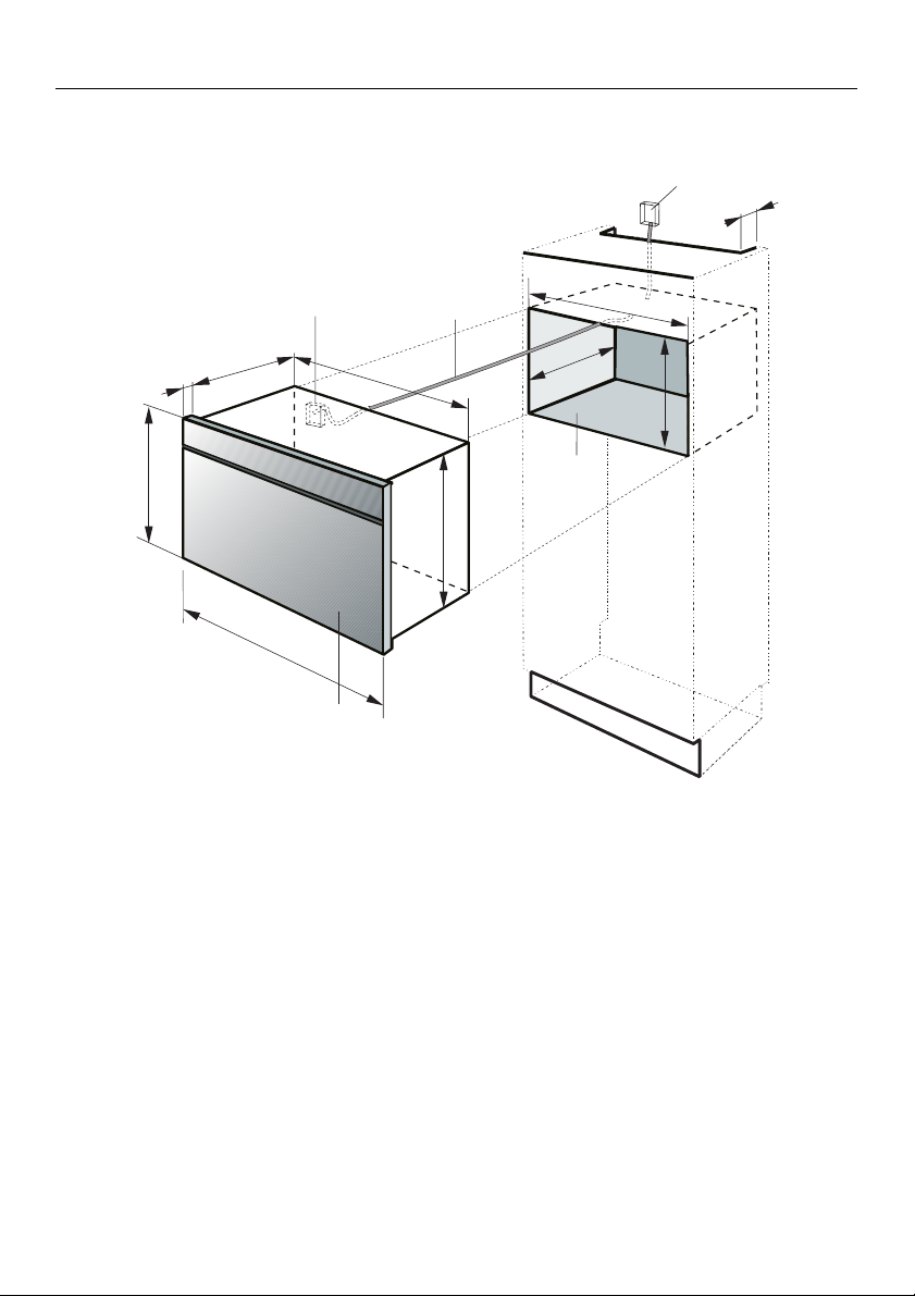
Installation in tall cabinetry
e
100
d
330
22
456
595
b
Steam oven
b
Cabinet opening
c
Terminal block
d
Outlet or junction box. This should
e
be accessible after the appliance
has been installed.
547
f
447
560-568
min.330
450
c
Power supply cord
f
4
Page 5

Appliance and cut out dimensions
Appliance and building-in dimensions
Installation under a counter
top
e
456
22
d
330
595
f
547
b
Steam oven
b
Cabinet opening
c
Terminal block
d
Outlet or junction box. This should
e
be accessible after the appliance
has been installed.
min.370
450
560-568
c
447
Power supply cord
f
5
Page 6

Appliance and cut out dimensions
Appliance and building-in dimensions
Installation above a Miele oven
330
22
d
547
f
e
100
456
b
596
595
g
595
22
Steam oven
b
Cabinet opening
c
Terminal block
d
Outlet or junction box. This should
e
be accessible after the appliance
has been installed.
447
547
580
550
min.330
560
c
560-568
450
c
560-568
593-595
Note:
The steam oven must be supported
by ledges or shelving. It must not
rest directly on top of the oven.
Power supply cord
f
Oven
g
6
Page 7

Installing the oven
Securing the oven
After aligning the oven it must be secured in position.
Open the oven door and using the supplied screws
cabinet through the holes on either side
of the vertical oven trim.
, secure it to the
h
Installing the oven
Conversion table
mm inches
22 7/8
100 3 15/16
330 13
370 14 9/16
447 17 3/4
450 17 11/16
456 17 15/16
547 21 9/16
550 21 11/16
560 22 1/16
568 22 3/8
580 22 13/16
593 23 3/8
595 23 7/16
596 23 1/2
7
Page 8

Installing the oven
All electrical work should be performed
by a licensed electrician, in strict accordance with national and local safety
regulations and standards.
Note to installer:
Please leave these instructions with
the consumer.
Power supply:
Please check the dataplate for verification of:
240 VAC; 60 Hz
15A, 240 V
L1, L2, Ground
Caution:
Disconnect main power supply before servicing. To reduce the risk of
electrical shock, make sure that the
appliance is properly grounded
after installation.
WARNING : THIS APPLIANCE
MUST BE GROUNDED
For USA only
The appliance is provided with 3 terminal leads, 1 black wire (L1), 1 red
wire (L 2) and 1 green wire (GND)
which have to be connected to a dedicated junction box. Connect the black
wire to L1, the red wire to L2 and the
green wire to GND.
ALSO SEE THE WIRING DIAGRAM
PROVIDED WITH THE APPLIANCE.
For CDN only
The appliance is provided with 3 terminal leads: 1 black wire, 1 red wire and
1 green wire which have to be connected to a separate overcurrent protection device (fusebox or circuit
breakers).
All hot wires (black and red) have to be
fused individually before connecting
them to the main power supply leads.
Use 15 Amp fuses or circuit
breakers for appliances rated 240
VAC.
8910
Connect black terminal wire to
L1 (black) and red terminal wire to
L2 (red). The green terminal wire
(ground) has to be connected directly
to the equivalent colored power supply
leads.
All connections must be done in a
proper way.
ALSO SEE THE WIRING DIAGRAM
PROVIDED WITH THE APPLIANCE.
Page 9

Page 10

Page 11

11
Page 12

Alteration rights reserved 00/3599
These instructions are printed on 100% recycled paper and are completely Biodegraable.
 Loading...