

Page 1

User's Guide
for the
Microtek ScanWizard
Scanner Software
PC Version
Page 2

Copyright © 1998 Microtek Lab, Inc.
All rights reserved.
Second Edition: May 1998
Microtek Lab, Inc.
3715 Doolittle Drive, Redondo Beach, CA 90278-1226
Main: (310) 297-5000
Sales: 800-654-4160
Tech Support: (310) 297-5100 (PC); (310) 297-5125 (Mac)
Fax: (310) 297-5050
AutoTech fax back: (310) 297-5101
Internet: http://www.microtekusa.com
Tech Support Web Page: http://www.support.microtek.com
Microtek International, Inc.
6, Industry East Road 3
Science Based Industrial Park
Hsinchu 30077, Taiwan, R.O.C.
Tel: 886-3-5772155Fax: 886-3-5772598
Worldwide Web Site: http://www.microtek.tw
Microtek Europe BV
Max Euwelaan 68
NL - 3062 MA Rotterdam
The Netherlands
Tel: 31-10-242-5688
Fax: 31-10-242-5699
Worldwide Web Site: http://www.microtek.nl
To obtain optimal results from the Microtek scanning software and user's guide, you should be familiar with such
Windows concepts as pointing, clicking, dragging, and selecting from menus and dialog boxes. If these things are new
to you, refer to your Microsoft Windows User’s Guide. Windows is a trademark of Microsoft Corporation. All other
product names are trademarks or registered trademarks of their respective holders.
Page 3

Table of Contents
ScanWizard Reference .........................................................................................1
ScanWizard: The Four Windows..........................................................................2
The Preview Window ...........................................................................................3
Elements of the Preview window..................................................................3
The Menu Bar................................................................................................4
The Scanner Menu ........................................................................................5
Scanner Model.................................................................................................... 5
Get Current Scanner Info.................................................................................... 5
Get SCSI Chain .................................................................................................. 6
Exiting ScanWizard............................................................................................ 7
The View Menu............................................................................................. 8
Full Page Preview............................................................................................... 8
Zoomed Preview............................................................................................... 10
Resize Window to Fit ....................................................................................... 11
Show / Hide commands.................................................................................... 11
The Preferences Menu.................................................................................12
Scan Material.................................................................................................... 12
The Scan Material icon..................................................................................... 13
Invert ................................................................................................................ 14
Horizontal Mirror ............................................................................................. 15
Cursor Auxiliary Lines ..................................................................................... 16
Preview Setup ................................................................................................... 18
Live Prevew .................................................................................................. 18
Color Preview............................................................................................... 18
Fast Preview ................................................................................................. 18
The Preview Area.......................................................................................... 19
Keep Preview Image......................................................................................... 20
Smoked Glass Background .............................................................................. 20
How Smoked Glass works with image enhancement.................................... 21
More ................................................................................................................. 22
The Help Menu............................................................................................23
About ................................................................................................................ 23
The T oolbar ................................................................................................. 24
Zoom Preview tool ........................................................................................... 25
Scan Frame tool ................................................................................................ 26
Magnifying Lens tool ....................................................................................... 27
Pane tool ........................................................................................................... 28
Color Picker tool (Set Shadow / Highlight) ..................................................... 29
Action buttons ............................................................................................. 31
Rulers .......................................................................................................... 32
Preview Area ...............................................................................................33
Page 4

The Untitled Job1 (Settings) Window ................................................................ 34
Elements of the Settings window ................................................................34
Output Image Parameters ............................................................................35
Type (Image Type or Scan Mode) .................................................................... 35
Resolution....................................................................................................36
Optical vs. interpolated resolution.................................................................... 36
Choosing the best resolution setting................................................................. 37
When to use high resolution ............................................................................. 37
When to use interpolated resolution ................................................................. 37
Unit Selection .............................................................................................. 38
Image Dimension controls ..........................................................................39
How to use the Input-Output dimensions ......................................................... 40
Input dimensions........................................................................................... 40
Output dimensions ........................................................................................ 41
How to use the Aspect Lock............................................................................. 42
Scaling ......................................................................................................... 43
Image Adjustment controls..........................................................................44
Auto (Automatic Contrast Control).................................................................. 44
Color Correction / DCR ................................................................................... 45
Image-Enhancement T ools .......................................................................... 46
What the Image Enhancement tools are ........................................................... 47
Using the Advanced Image Enhancer dialog box............................................. 48
The Action Buttons in the AIE dialog box ....................................................... 49
Brightness, Contrast and Exposure tool ........................................................... 50
The BCE screen (for grayscale and color)................................................... 51
The BCE screen (for line art) ....................................................................... 52
How to use the BCE tool .............................................................................. 53
Tints tool........................................................................................................... 54
The Tints screen ............................................................................................ 55
How to use the Tints tool .............................................................................. 56
Shadows and Highlights tool............................................................................ 57
The Shadows and Highlights screen............................................................. 58
How to read and correct a histogram........................................................... 60
How to use the Shadows and Highlights tool ............................................... 61
Curve tool ......................................................................................................... 62
How to read the curve .................................................................................. 62
Sample images and their curves ................................................................... 63
The Curve screen .......................................................................................... 64
Using the curve buttons ................................................................................ 65
How to use the Curve tool ............................................................................ 66
Filters tool......................................................................................................... 67
Blur filters..................................................................................................... 68
Sharpen filters .............................................................................................. 68
Edge Enhancement filter .............................................................................. 69
Emboss filter ................................................................................................. 69
Unsharm Mask filter..................................................................................... 70
More Options tool ............................................................................................ 71
Descreen ....................................................................................................... 72
Scan Quality ................................................................................................. 73
Gray Scan CCD Filter.................................................................................. 73
Use Linear Gamma Curve............................................................................ 73
The Window Expansion button................................................................... 74
Page 5

The Information Window ...................................................................................75
Elements of the Information window.......................................................... 75
Using the Zoom Level Display ...................................................................76
Using the Cursor Locator ............................................................................ 76
Using the Color Meter Display ...................................................................77
Using the Sample Size button .....................................................................78
Value and Percent ............................................................................................. 78
Sample Size Options ........................................................................................ 79
Using the Pixel Display............................................................................... 79
The Scan Job Window........................................................................................80
Elements of the Scan Job window...............................................................80
How to read the Scan Job window ..............................................................81
The New button ........................................................................................... 82
More Applications ............................................................................................ 85
The Duplicate button ................................................................................... 86
The Save button...........................................................................................87
The Add button ............................................................................................87
The Check button ........................................................................................ 87
The Delete button ........................................................................................87
The Up/Down Position Arrows................................................................... 88
Page 6

ScanWizard Reference
This is a reference manual for ScanWizard, your Microtek scanner controller driver.
The reference information is organized in four parts, following the structure of the
software which shows the four major windows of the program (Preview, Settings,
Information, and Scan Job).
ScanWizard acts as a bridge between your scanner and your image-editing software
(such as Adobe Photoshop or Ulead PhotoImpact). ScanWizard captures the image
placed on your scanner and then delivers the image when it is scanned to the imageediting software, where the scanned image can then be saved, printed, or edited
further.
Here are some things you can do with ScanWizard:
• Select the type of image to be scanned. For example, you can have a color photo
and scan it in the same color mode, or you can scan it in a different mode such as
grayscale or line art.
• Perform a preview, which allows you to see a preliminary view of the image
before it's actually scanned.
• Use the image-enhancement tools to adjust image features such as brightness and
contrast, or to apply filters and special effects.
• Create multiple scan jobs. For example, one scan job may be in grayscale and
another may be in color. The two scan jobs can then be manipulated and scanned
separately, and you can switch between scan jobs easily while making changes.
ScanWizard's ability to process various scan jobs concurrently adds tremendous
flexibility to scanning.
Page 7
ScanWizard: The Four Windows
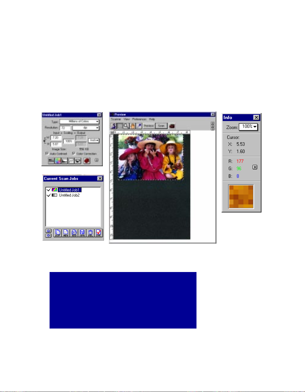
ScanWizard consists of four major windows: Preview, Settings, Information, and Scan Job.
The Preview and Settings windows appear automatically after ScanWizard is started up. The Scan Job and
Information windows, however, are hidden, and to see them, go to the View menu in the Preview window
and click on the commands Show Scan Job window and Show Info window.
Settings window
Scan Job window
Preview window
Whenever ScanWizard is started, only the
Preview and Settings windows appear. To see the
Scan Job and Information windows, go to the
View menu and choose the Show Scan Job
window and Show Info window command.
5-2 Microtek Scanner User's Guide (PC version)
Information
window
Page 8
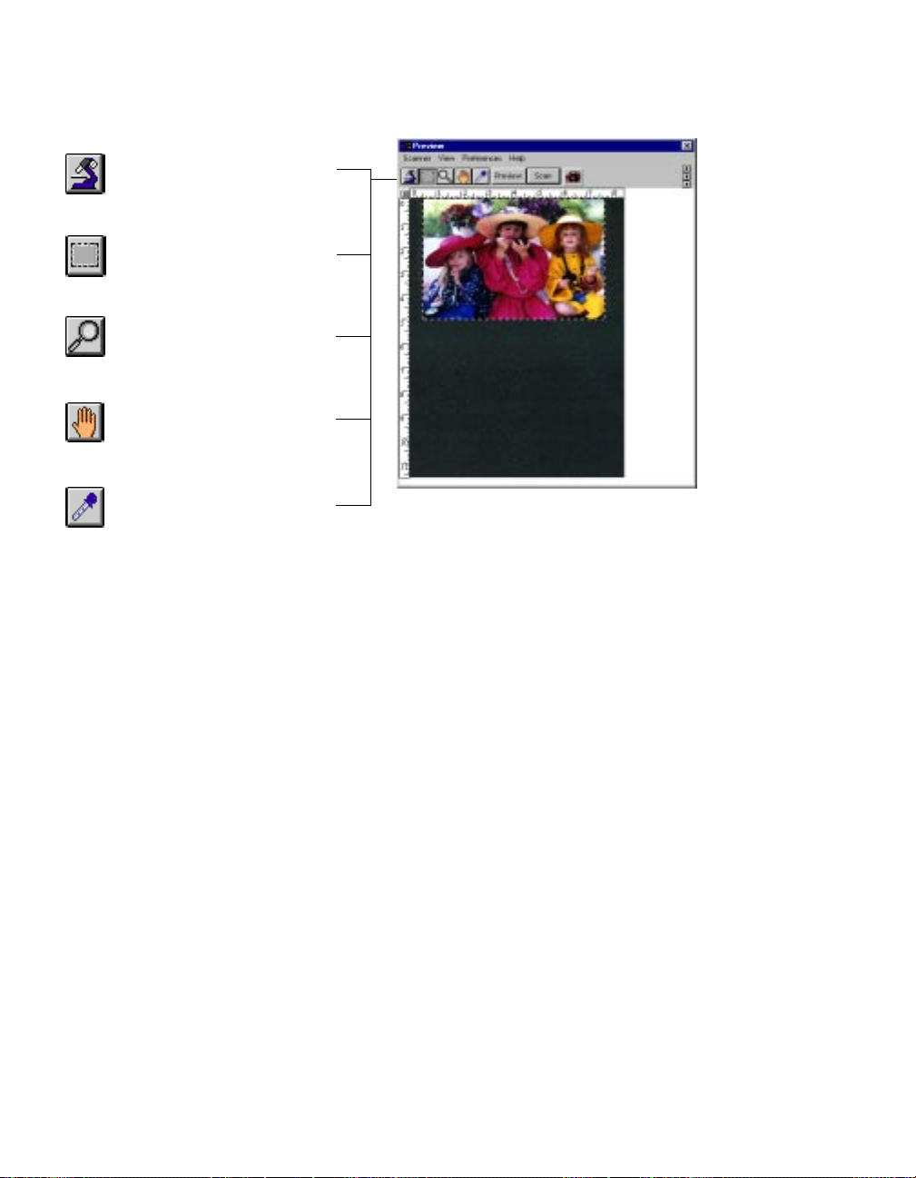
The Preview Window
The Preview window is the most prominent window of the four major windows, and it
includes the various commands and tools for controlling the scanner.
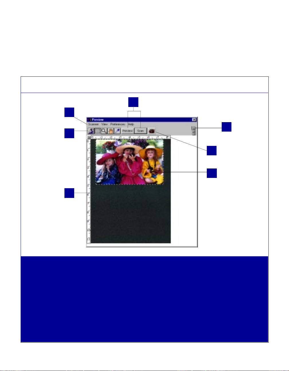
Elements of the Preview window
1
2
6
3
7
4
5
1 The Menu Bar includes the
different menus for controlling
ScanWizard.
2 The Toolbar simplifies the
performance of certain tasks.
3 The Action buttons generate a
specific action from the
scanning software. The Action
buttons include Preview and
Scan.
4 The Scan Material Status icon
shows your scan material,
whether it's reflective, positive, or
negative.
5 The Preview Area is where the
preview image appears after you
click on the Preview button.
6 Rulers are located on both sides
of the window to help you with
measurement and alignment.
5-3Reference
Page 9
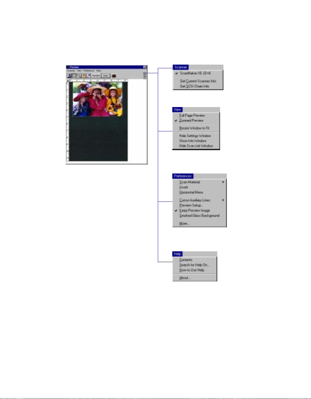
The Menu Bar
5-4 Microtek Scanner User's Guide (PC version)
Page 10
The Scanner Menu
The Scanner Menu lets you:
• Show your scanner model or select a scanner if you have multiple scanners
• Get information about your scanner
• Get information about the SCSI chain
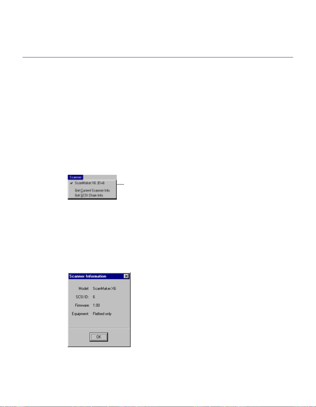
Scanner Model
The top of the scanner menu displays the scanner model you're using and its SCSI ID. If
you have multiple scanners on your system, all the scanners are shown with their
respective SCSI IDs, and the current scanner is indicated by a check.
Only one scanner can be accessed at a time. To switch among various scanners, select
the scanner to be used.
The scanner is displayed
here with its SCSI ID. The
The current scanner is
marked by a check.
Get Current Scanner Info
This command provides information about your current scanner. A dialog box appears
showing the scanner model, SCSI ID number, firmware version, and other relevant
information.
5-5Reference
Page 11
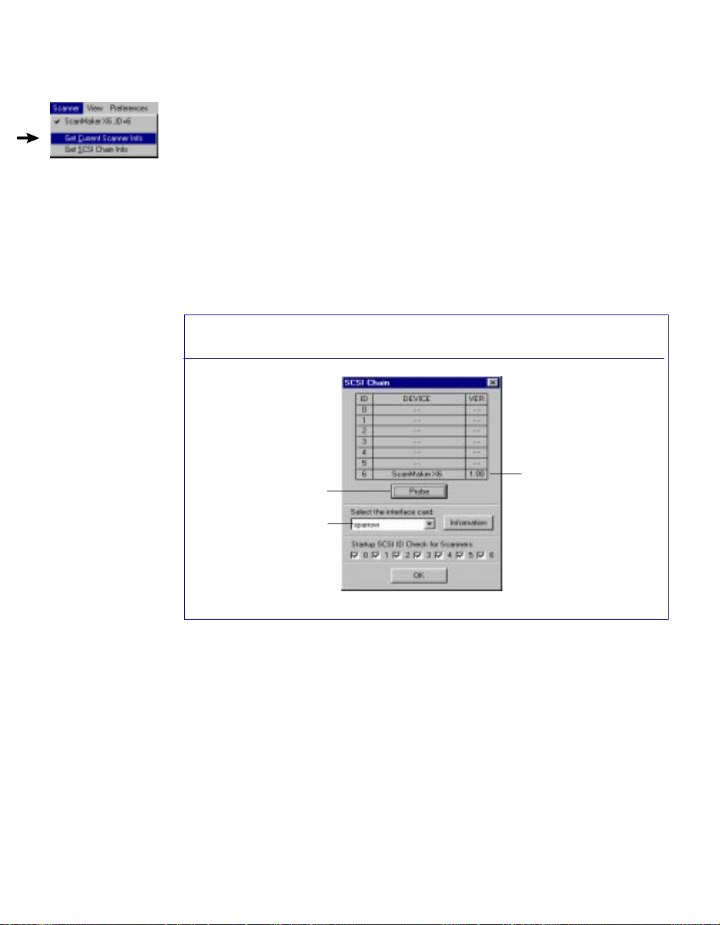
Get SCSI Chain Info
This command lets you see the SCSI devices on your SCSI chain and the SCSI ID
number of the devices.
By default, all numbers (located in the lower third of the dialog box) are selected
by the check boxes. To allow ScanWizard to start up more quickly, select only the
boxes that match the SCSI ID of your scanner (or scanners, if you have multiple
scanners on your system).
This will make ScanWizard bypass the numbers for your other devices and focus
effort on simply detecting scanners. If you're not sure about which numbers to
specify, check all the boxes.
The Get SCSI Chain Info dialog box
Click on the
Probe button
to update
information or
mount a SCSI
device if it's
not showing in
the dialog box
Make sure you
have the correct
interface card
here.
SCSI devices are
shown with their
corresponding
SCSI ID numbers
To use the Get SCSI Chain Info feature:
1 Choose the Get SCSI Chain Info command from the Scanner menu. The SCSI
Check dialog box will appear.
2 If your scanner does not show in the SCSI Check dialog box, click on the
Probe button. Make sure your scanner is connected and turned on.
3 Make sure that the correct interface card is shown in the card selection box.
4 Check the numbered box corresponding to the SCSI ID of your scanner or
scanners.
5. Click OK to close the dialog box.
5-6 Microtek Scanner User's Guide (PC version)
Page 12
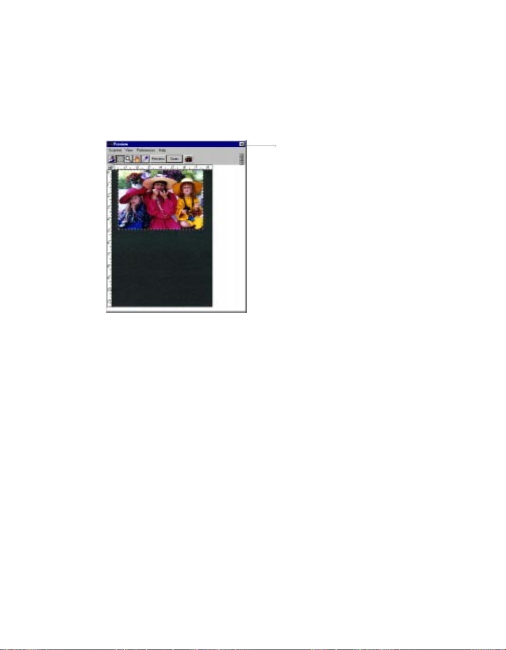
Exiting ScanWizard
To exit ScanWizard for Windows, double click on the "X"
on the upper right corner of the Preview window.
Double-click here to
exit ScanWizard
5-7Reference
Page 13
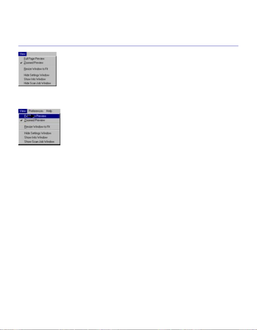
The View Menu
The View menu lets you:
• Get a full page preview or enlarged, h ig-resolution view of an image
• Resize the preview window
• Show or hide the Settings, Information, and Scan Job windows
• Obtain information on ScanWizard
Full Page Preview
This command shows you a full preview of your image. Take note of the
following:
• The Full Page Preview is defined by the parameters set in the Preview Setup
command (in the Preferences menu). For instance, if your image is 8" x 5"
but the dimensions in the Preview Setup are 4" x 3", your full page preview
will be 4" x 3".
• The maximum size of the Full Page Preview varies, depending on your
scanner model. For example, if the scan bed (the glass surface) of your
scanner has a maximum size of 8.5" x 13", the maximum full page preview
will be limited to those dimensions.
• The size of the full page preview can be changed by setting new dimensions
in the Preview Setup command. The new dimensions will take effect,
however, only with the next preview. This means you need to click on the
Preview button so that the scanner does a new preview; only then will you
see the new dimensions of the Full Page Preview.
• You may wish to change the size of your Full Page Preview to improve
performance and save memory. A smaller preview area will occupy less
memory, speed up processing, and yield a higher-resolution preview.
5-8 Microtek Scanner User's Guide (PC version)
Page 14
Comparison of Full Page Previews as determined by the Preview Setup
1
Preview area matches
dimensions in Preview
Setup command
2
2
Full page preview
(8.5" x 11") as
determined by
dimensions in the
Preview Setup
Full page preview
changes to 6" x 9"
because dimensions
in Preview Setup were
changed
Preview area changes
as dimensions change.
Note new ruler
measurements.
To use Full Page Preview:
Full Page Preview is the default view. The option will be dimmed in the View menu if the current
view is already the Full Page Preview.
1 To change the size of the full page preview, click on the Preview Setup command in the
Preferences menu. When the Preview Setup dialog box appears, specify the new dimensions
for the full page preview. (See the Preview Setup command for more details.)
2 To make the new preview dimensions take effect, do a new preview by clicking on the
Preview button, and in a few moments, the new preview area will appear.
5-9Reference
Page 15
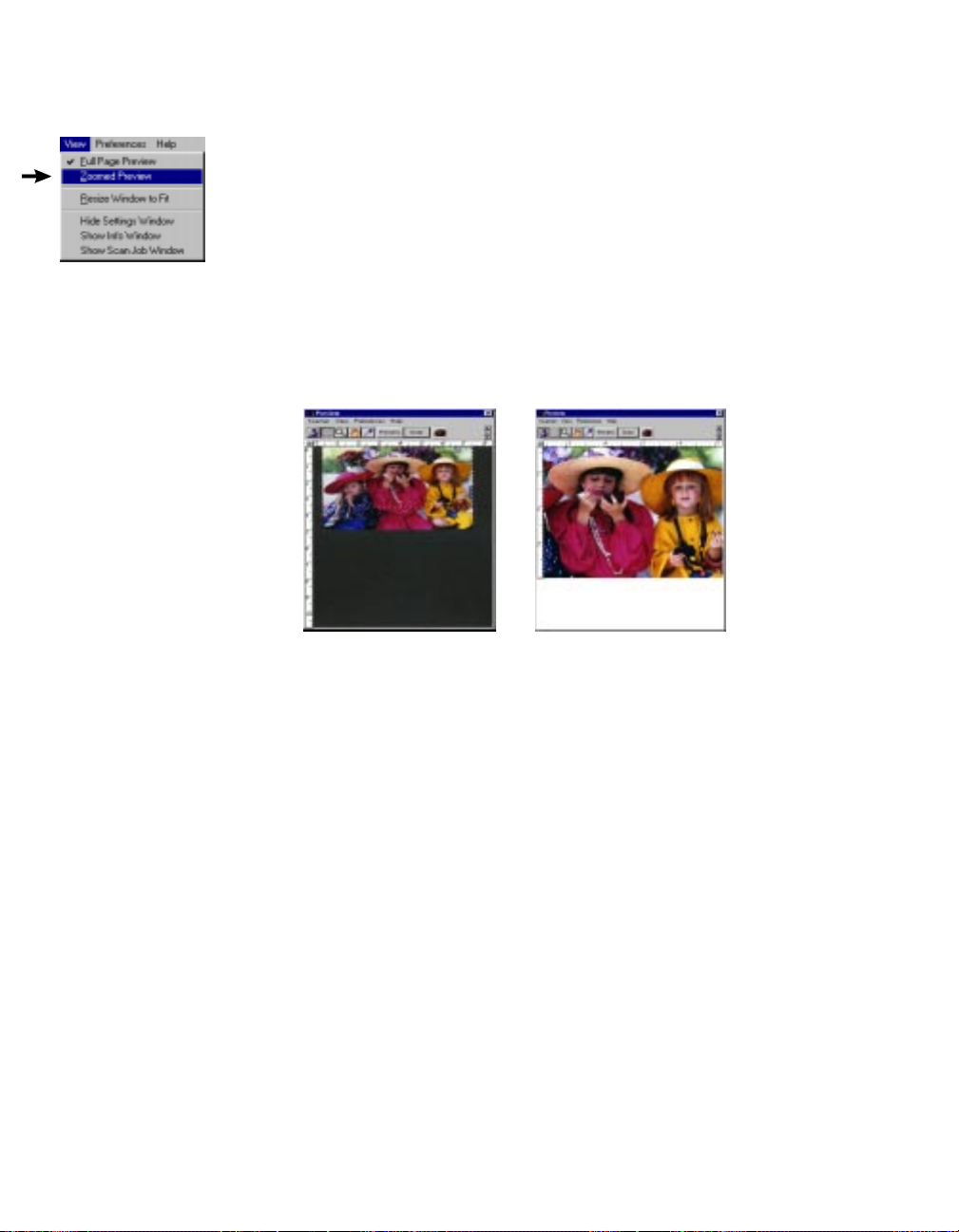
Zoomed Preview
This command displays a magnified view of the preview when you use the Zoom
Preview tool.
The zoomed preview shows a specific part of the preview image in higher resolution and with more visible detail. If you have zoomed preview enabled, the view is
stored in memory, and you can easily switch between full page preview and
zoomed preview.
The zoomed preview is different from the zoomed-in view obtained from the
Magnifying Lens tool. The zoomed-in view is simply an enlarged view, but it is
not in high resolution.
Full page preview
To use Zoomed Preview:
1 Click on the Zoom Preview tool (leftmost tool in the Toolbar that looks like a
microscope).
2 Move the pointer to the preview image and draw a scan frame around the area
to be zoomed in, then click inside the scan frame. The selected area will be
magnified to give you the zoomed preview.
After you use the zoom preview tool to create the zoomed preview, the
Zoomed Preview option in the View menu will be enabled. You can then
switch between Full Page Preview and Zoomed Preview as your viewing
modes.
For more details, refer to the section on the Zoom Preview tool.
5-10 Microtek Scanner User's Guide (PC version)
Zoomed preview
Page 16
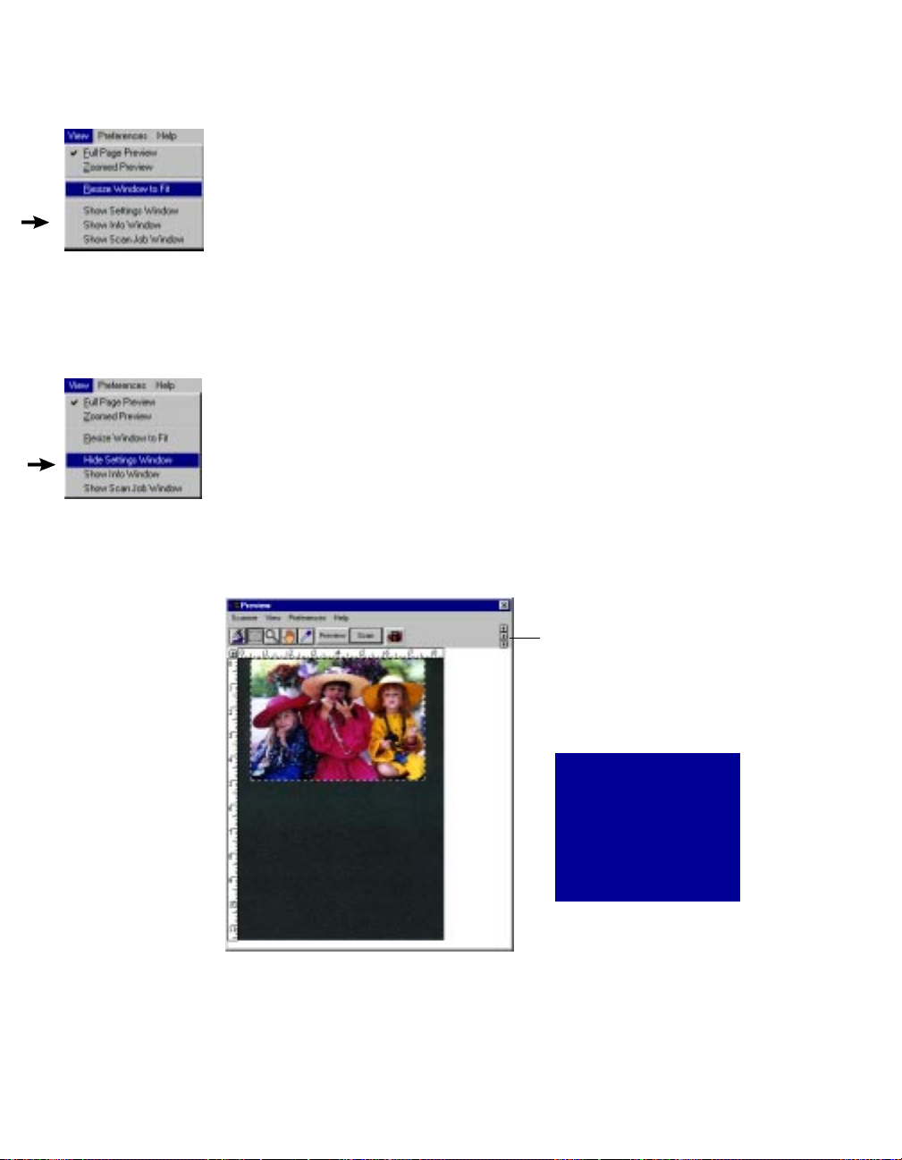
Resize Window to Fit
This command adjusts the preview window to fit the preview area, so that the
preview space is used more efficiently.
To use this feature:
Choose the command Resize window to fit in the View menu.
This command is available only if the current zoom level is 100%, and is disabled if
zoom is set to other levels. To verify the zoom level, open the Information window
and look up the zoom level.
Show / Hide commands
Allow you to switch between showing or hiding the Settings, Scan Job, and Information windows on your screen. The commands also have their toolbar counterparts
in the form of three arrowheads on the right edge of the toolbar.
To use this feature, do either of the following:
• Toggle the command to show or hide the respective window on your screen.
• Click on the Show/Hide tool buttons in the Preview window.
Click arrows here
to show or hide
the Settings,
Preview, and
Scan Job Window
Note: Do not doubleclick the close box of the
Preview window because
this will cause you to exit
the program.
5-11Reference
Page 17
The Preferences Menu
The Preferences menu lets you:
• Choose the correct scan material
• Create effects like invert and mirror
• View cursor lines to help you with alignment
• Control the size of your preview window
• Keep your last preview image after you finish scanning
• Create a smoked glass background to help distinguish the active scan frame
• Set other options, such as specifying a working directory for files
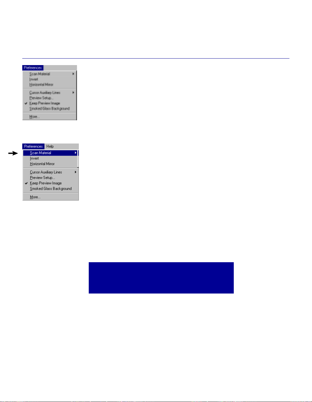
Scan Material
This command allows you to select the correct scan material, which can
be classified into three types:
• Reflectives (such as photographs or prints)
• Positives
• Negatives
The options available to you in the Scan Material submenu will depend
on your equipment. For instance, the positive and negative option will be
active only if you're using a Transparent Media Adapter (TMA) with
your scanner.
If you are scanning negatives or positives, make sure you specify the
correct scan material before scanning the image, or you will get inaccurate scanning results.
The Scan Material function is also related to the Tints tool,
an image-enhancement function in the Settings window.
Refer to that section for more details.
12 Microtek Scanner User's Guide (PC version)
Page 18
To use the scan material feature:
Choose the Scan Material command in the Preferences menu. From the submenu that
appears, select your scan material; a check appears next to the selected option. The
option you select will also be shown in the Scan Material Status icon (discussed below).
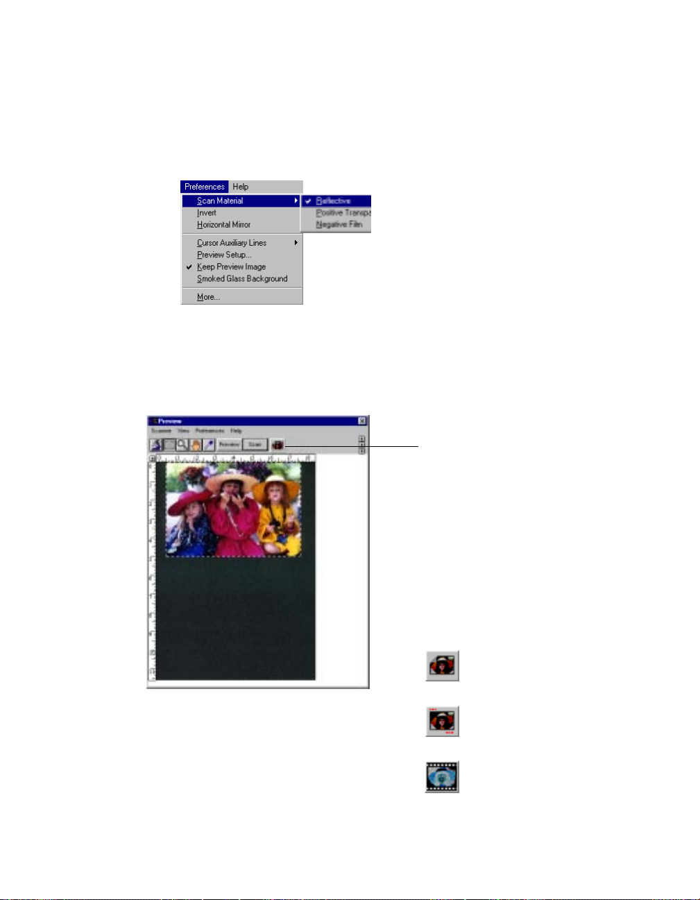
The Scan Material icon
Another way to access the Scan Material menu is to use the Scan Material icon, located
to the right of the Scan Button.
Scan Material icon
The appearance of the Scan Material
icon changes, depending on whether
your scan material is reflective,
positive, or negative. Note: The
positive and negative icons become
active only if you're using a Transparent Media Adapter with your flatbed
scanner, or if you're using a transparency / slide scanner such as the
ScanMaker 35t Plus.
Scan Material icon when
scanning reflectives
Scan Material icon when
scanning positives
Scan Material icon when
scanning negatives
Reference 13
Page 19
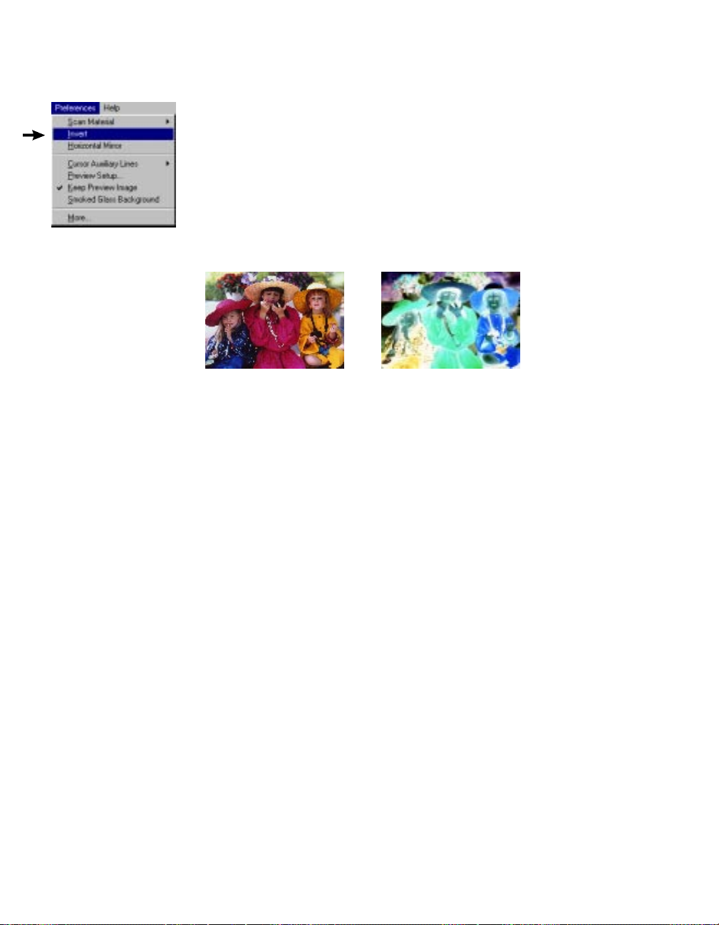
Invert
This command creates a negative of an image. The Invert effect is applied to
the whole preview image; it cannot be used for only a specific portion of the
image.
When an image is inverted, the brightness value of each pixel is converted to
the inverse value on the 256-step color values scale. For example, a pixel in a
positive image with a value of 255 is changed to 0, and a pixel with a value of 5
is changed to 250.
InvertOriginal
To use this feature:
Choose the Invert command in the Preferences menu. A check appears next to
the command when it is enabled.
14 Microtek Scanner User's Guide (PC version)
Page 20
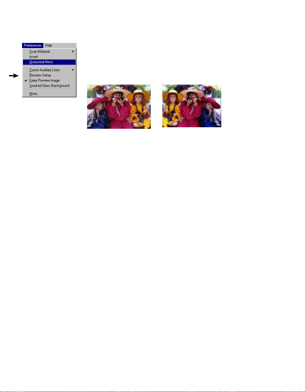
Horizontal Mirror
This command allows you to flip the image so that a mirror effect is created.
The Mirror effect is applied to the whole preview image; it cannot be used for
only a specific portion of the image.
Horizontal MirrorOriginal
To use this feature:
Choose the Horizontal Mirror command in the Preferences menu. A check
appears next to the command when it is enabled.
When the mirror image appears, the scan frame will still be in the old location,
and you will need to move the scan frame if you wish to define another area.
Reference 15
Page 21
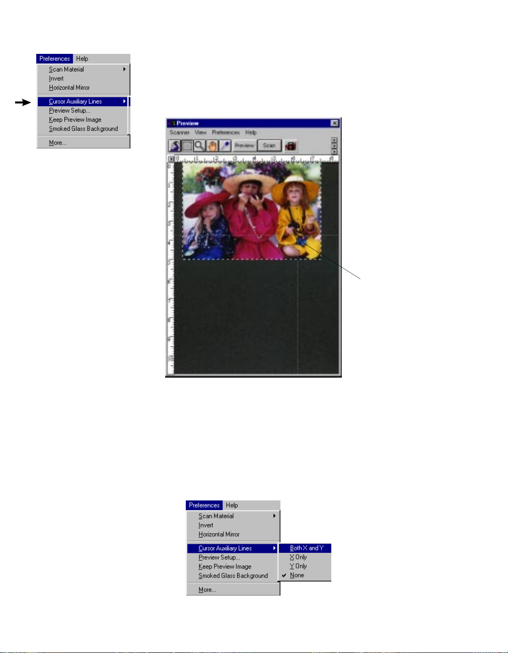
Cursor Auxiliary Lines
This command allows you to create horizontal and vertical grid lines
with your cursor to help define a scan frame precisely. Using the grid
lines, you can read the measurements off your ruler more easily.
Cursor auxiliary lines
on the x and y axis
To use this feature:
1 Choose the Cursor Auxiliary Lines command in the Preferences
menu. From the submenu that appears, select how the cursor lines
will appear.
• On both x (horizontal) axis and y (vertical) axis
• On x axis only
• On y axis only
• None (no cursor lines)
16 Microtek Scanner User's Guide (PC version)
Page 22
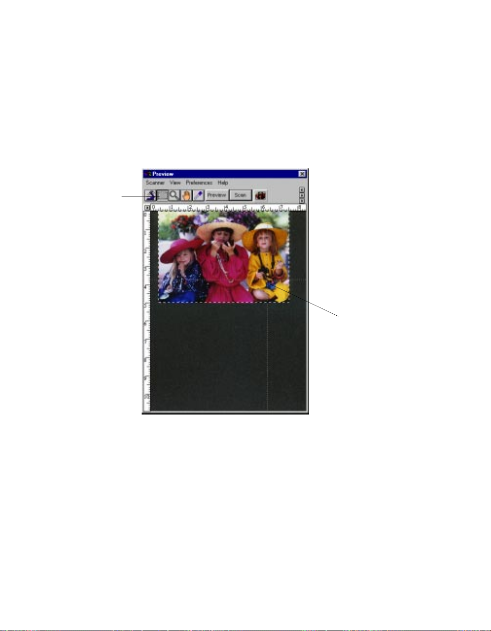
2 Click on the Scan Frame tool.
Click on the
Scan Frame
tool, then
define a
starting point.
To see how the cursor lines work, draw a scan frame. Click on
the top left corner of the image as your starting point, then drag
down to form a scan frame.
As you draw the scan frame, cursor lines will appear to help you
draw the scan frame precisely. When you release the mouse,
your scan frame will be aligned with the cursor lines.
As you drag the
mouse down, the
scan frame is
aligned with cursor
lines on the x and y
axis (based on your
selected option in
the submenu).
Reference 17
Page 23

Preview Setup
This command allows
you to set the dimensions of your preview
area. When the Preview
Setup dialog box
(below) comes up,
click on the option you
need or specify your
parameters.
Option
Live Preview
Color Preview This option is enabled only if Live Preview is not selected. If this option is turned on, the
Fast Preview
Description of function
This option applies only to color scanners. If Live Preview is enabled, the next option, Color
Preview, will be dimmed.
If Live Preview is on:
• Changes you make to the preview image are shown instantly (for example, switching
from color to grayscale).
• If you're scanning in grayscale and live preview is on, the image appears in color unless
you specifically change image type in the Type box (in the
grayscale mode. This happens because Live Preview always does previews in color.
If Live Preview is off:
Your preview will be in accordance with your image type (i.e., if you have a grayscale
image, your preview is in grayscale; with a color image, you get a color preview). If you
apply any image-enhancement control, the changes will not be apparent until you do a new
preview (click on the Preview button again). Turn off Live Preview if you're previewing or
scanning in grayscale to speed up the process.
image will be scanned in whatever scan mode is specified in the Type box (in the Settings
window). If it is turned off, the image will be scanned in grayscale.
This option allows you to choose your preview mode.
• On: The preview process is faster, but the quality of preview image is a little coarse.
• Off: The preview process is slower, but the quality of the preview image is improved.
The Fast Preview option is a hardware-related feature and may or may not be available
depending on your scanner model.
Untitled Job1
window) to a
18 Microtek Scanner User's Guide (PC version)
Page 24
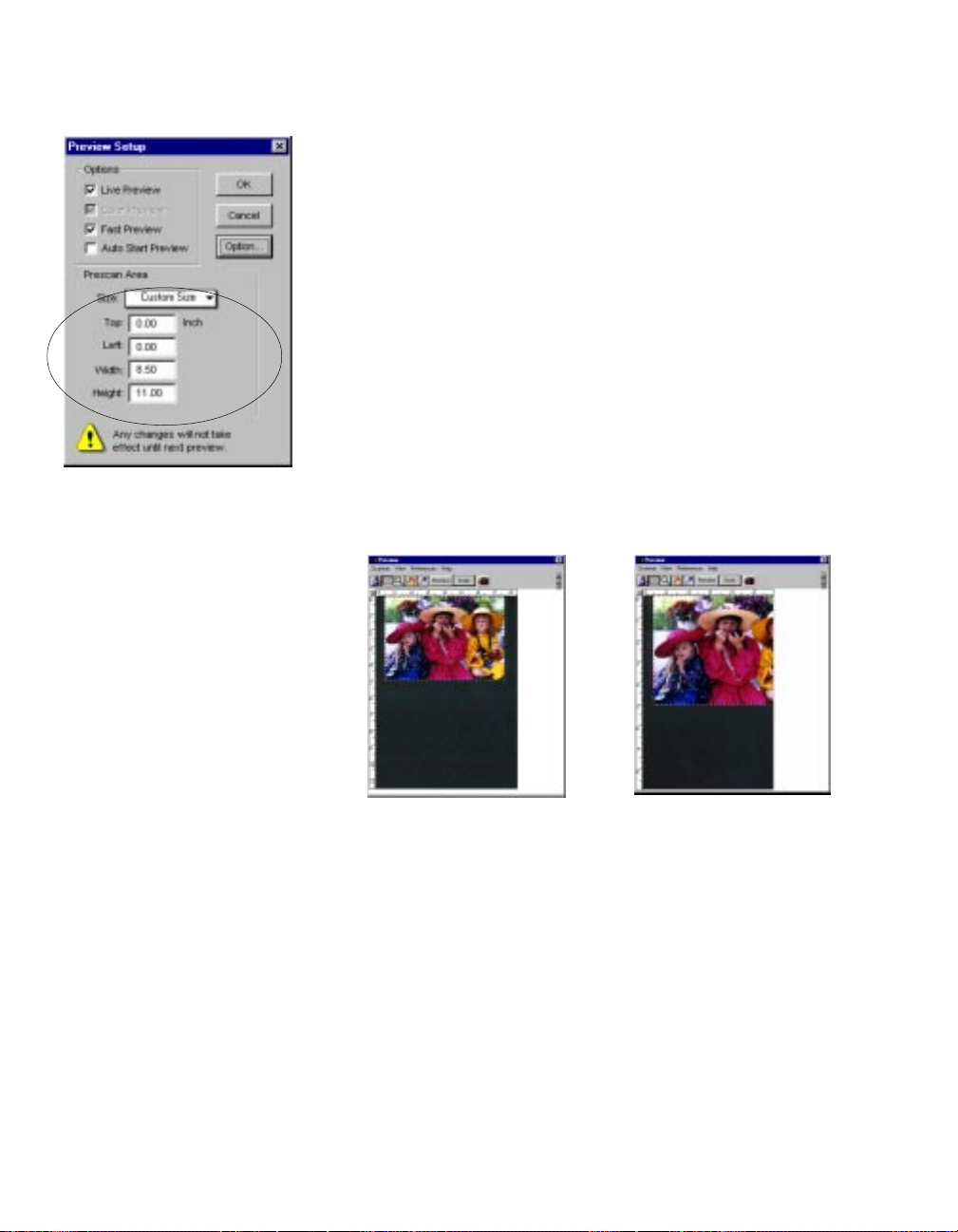
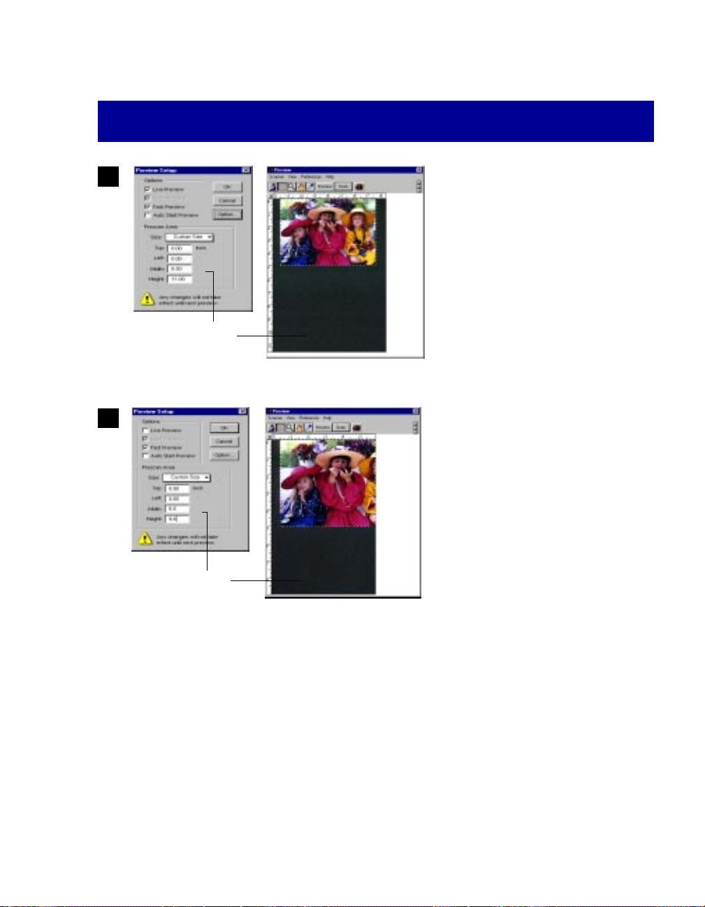
The Preview Area
The Preview Area option in the Preview Setup dialog box lets you
select the size of your preview area. Choose from the following
options: letter, A4, legal, maximum size, or custom size.
• Maximum refers to the maximum scan area that can be supported
by your particular scanner model.
• Custom will appear if you type in your own specifications and
change any of the edit boxes.
• The Top, Left, Width and Height edit boxes allow you to specify
the dimensions of the preview area. Top and Left refer to the
starting points of the preview area on the x and y coordinates.
Width is the expanse of the preview area, and Height is the depth
of the preview area.
• The unit of measurement, indicated on the right side of the Left
box, reflects the unit selected in the Settings window.
Size of preview area if
preview setup is 8. 5" x 11"
Size of preview area if
preview setup is 6" x 9"
To set the preview area:
1 Choose the Preview Area size. If you enter any of the edit boxes
marked Top, Left, Width, or Height, the Preview Area size
automatically changes to Custom.
2 Click OK to accept the settings; click Cancel to abandon.
3 To make the new preview dimensions take effect, do a new
preview by clicking on the Preview button. In a few moments, the
new preview area will appear.
Reference 19
Page 25
Keep Preview Image
This command allows you to retain the last preview image you used, and the
preview image is kept in the preview window after you exit ScanWizard.The
next time you start up ScanWizard, this last preview image is again displayed in
the preview window.
To use this feature:
Choose the Keep Preview Image command in the Preferences menu. A check
mark appears next to the command when it is enabled.
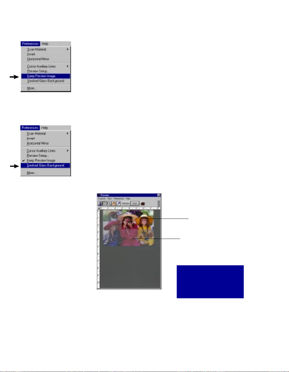
Smoked Glass Background
This command helps you distinguish the scan frame from the rest of the
preview image for greater visibility of the scan frame.
With this feature turned on, the part of the image within a scan frame will
stand out, while any material not in a scan frame is relegated to the smoked
glass background. If you have multiple scan frames, all the scan frames
will be visible, and the current scan frame will be denoted by the marquee
(marching ants).
Current scan frame
(pulsing lines or
"marching ants"
marquee)
To use this feature:
Choose the Smoked Glass Background command in the Preferences menu. A check
appears next to the command when it is enabled. It is helpful to enable this feature,
especially when you are editing a scan frame or applying image-enhancement
controls. See the next section for more details.
20 Microtek Scanner User's Guide (PC version)
Part of image not in any
scan frame and also
hidden by smoked glass
background
Holding down the Shift key
while dragging the mouse
allows you to make multiple
scan frames.
Page 26
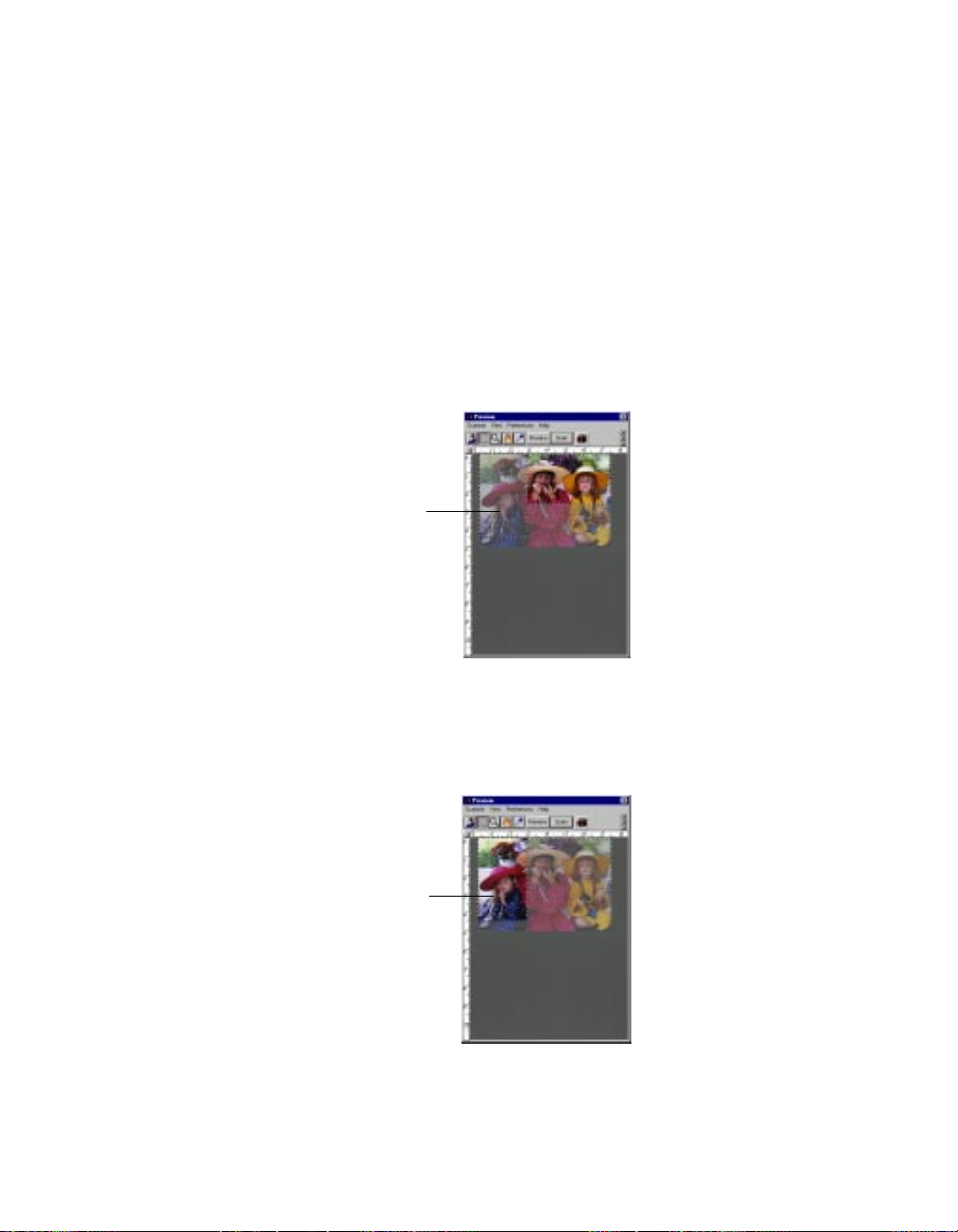
How Smoked Glass works with image enhancement
When the Smoked Glass feature is enabled, it becomes linked with the functions of the
scan frame and signficantly impacts the way image-enhancement controls and other
settings (such as resolution) are applied. Details follow.
• If you have turned on smoked glass, defined a scan frame, and set image-enhancement and other controls (such as changing brightness, applying a filter, or changing
resolution), the enhancements are applied to the scan frame alone.
This means that the part within the scan frame may change in appearance (as it now
has different settings), but because smoked glass is on, the rest of the image hidden
behind the smoked glass remains unaffected.
With Smoked Glass
on, controls are
applied to the part of
the image within the
scan frame. Notice
how right half of image
remains behind
smoked glass.
• If you have turned off smoked glass, defined a scan frame, and set image-enhancement and other controls, the enhancements are applied to the entire image, not just
the scan frame alone.
With Smoked
Glass off, controls
are applied to the
entire image.
Reference 21
Page 27
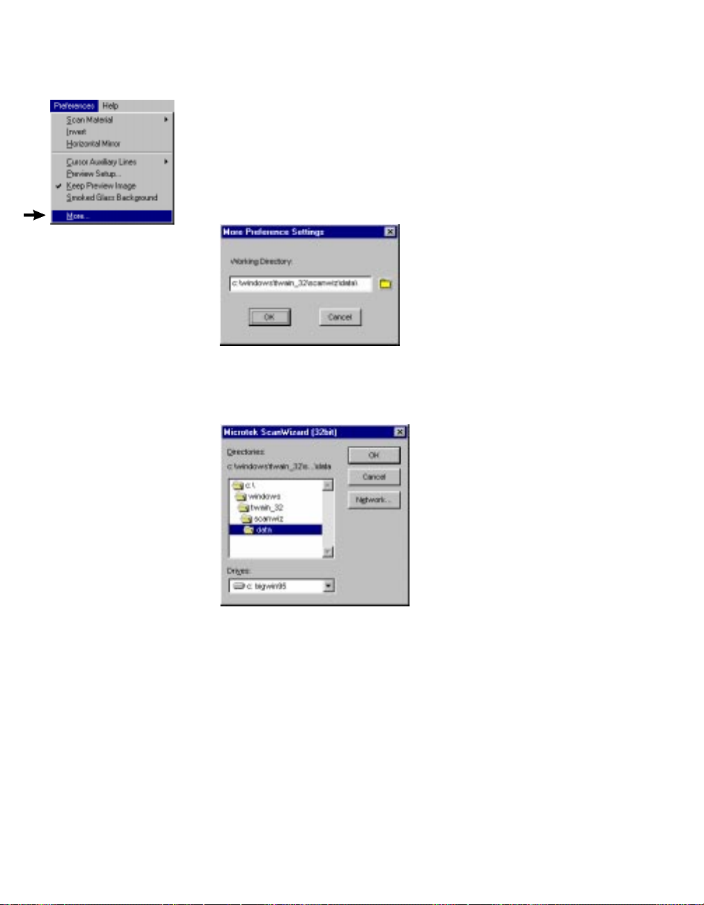
More
This command allows you to specify a working directory where you can save all
temporary and data files, including files for job templates.
To use this feature:
1 Choose the More command in the Preferences menu. The dialog box below
appears.
2 Click and hold down the Working Directory box, and from the pop-up
menu that appears, choose your working directory.
3 If you choose Other Directory from the menu, a standard dialog box will
appear where you can specify the working directory of your choice.
Whatever directory you specify is automatically added to the pop-up menu
above for you to choose from in the future. If the directory you specify is
not found or does not exist, a warning message appears, and the current
directory of the ScanWizard is used instead.
4 When you have completed your choices, click OK to close the More
Preferences dialog box. For the changes to take effect, exit ScanWizard,
then relaunch the program.
22 Microtek Scanner User's Guide (PC version)
Page 28
The Help Menu
The Help menu lets you access online help for ScanWizard.The Help menu uses
standard Windows conventions for obtaining online help. If you are not familiar with
this procedure, refer to your Microsoft Windows user's guide.
About
This command shows you the "splash" screen for
ScanWizard and the version number of the program.
Reference 23
Page 29
The Toolbar
Zoom Preview
Scan Frame
Magnifying Lens
Pane
Color Picker
24 Microtek Scanner User's Guide (PC version)
Page 30

Zoom Preview tool
Usage
To magnify the view of a
preview image in high
resolution, and to let you
switch between full page
preview and zoomed
preview.
The Zoom Preview tool gives you the zoomed preview, which is an
enlarged, high-resolution view of an image with more visible detail.
The zoomed preview is different from the zoomed-in view, which is
obtained by using the magnifying lens tool and is not a high-resolution
view. By using the zoom preview tool and creating the zoomed preview,
you can then switch easily between full page preview and zoomed preview.
Full page preview
Area to be
zoomed in
with the
Zoom
Preview tool
Zoomed preview
Selected image
part zoomed in
(enlarged) in high
resolution
To use the Zoom Preview tool:
1 Click on the Zoom Preview tool.
2 Move the pointer to the preview image and draw a scan frame around
the area to be zoomed in.
3 Click inside the scan frame. The selected area will be magnified to
give you the zoomed preview. Only the area inside the defined scan
frame will be zoomed in. To zoom in on a larger area, go to full page
preview and change the size of the scan frame.
25Reference
Page 31
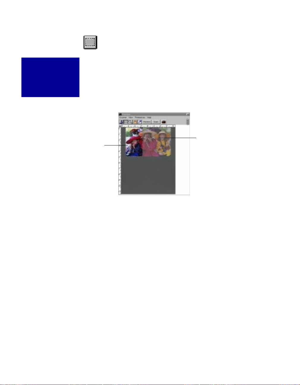
Scan Frame tool
Usage
To create a scan frame
or multiple scan frames
in the preview image.
Current
scan frame
The Scan Frame tool lets you create or modify a scan frame, which is the
active area on which controls and commands can be applied. You can have
multiple scan frames, but only one scan frame can be current at a time; the
current scan frame is indicated by a marquee (marching ants). If you have
multiple scan frames, the current scan frames can be more easily distinguished if you turn on the Smoked Glass Background command (in the
Preferences menu).
Another scan
frame, which can
be distinguished
by the marquee
around the left
half of the image.
Image with multiple scan frames
To use the Scan Frame tool:
1 Click on the Scan Frame tool.
2 Move the pointer (now a crossbar) to the preview image, and draw a
frame enclosing the area to be selected. When you release the mouse,
the scan frame will be in a marquee. To make multiple scan frames
(which would add scan jobs), hold down the Shift key and drag the
mouse. For more information on scan jobs, refer to the Scan Job
section.
3 To resize the scan frame, do either of the following:
• Move the cursor to any corner of the frame; the pointer will change
to a double-headed arrow. Hold down the mouse, and drag to form a
new area, then release the mouse; or
• Click on the Scan Frame tool again and restart the area-selection
process.
26 Microtek Scanner User's Guide (PC version)
Page 32

Magnifying Lens tool
Usage
To enlarge your view
of the preview image.
Note
If the
Information
window is open,
the zoom level
will be
indicated.
This means you
can also zoom
in by selecting
the appropriate
zoom level in
the Information
window.
The Magnifying Lens tool enlarges your view of the preview image,
allowing you to set the scan frame with greater precision if you need to.
Only your view of the preview image is changed; the actual size of the
image remains unaffected.
Each click of the lens tool magnifies or reduces by a factor of 2. Thus, the
magnification levels increase from 100% to 200%, to 400%, to 800%, and
to the maximum 1600% (see Note below). When you reach the maximum
magnification factor, the center of the lens tool will appear empty.
If the portion that you want to magnify includes most of the preview area,
the lens tool will magnify the view only slightly. To solve this, enlarge the
size of the preview area (through the Preview Setup command), or create a
smaller selection area.
Original image view
Image view enlarged with
Magnifying Lens tool
To use the Magnifying Lens tool:
1 Click on the Magnifying Lens tool.
2 Place the pointer — now a lens with a plus sign inside it — on the
image and click.
To reduce the view, hold down the Option key and click again. The
plus sign changes to a minus sign when you hold down the Option key.
27Reference
Page 33

Pane tool
Usage
To scroll through an
image and move
parts of it into view.
The Pane tool lets you scroll through a preview image, allowing you to
move parts of the image into view.
The Pane tool can be used to include zoomed-in images (enlarged through
the Magnifying Lens tool), or images not included completely within the
frame of the preview window (for instance, if your preview image is 8
inches wide and you resized the width of your preview window to only 5
inches).
Zoomed-in image
of three girls
Image moved
Zoomed-in image
Scrolled image
in from the
right. Girl on
extreme left is
now out of the
view frame.
To use the Pane tool:
1 Click on the Pane tool.
2 Move the pointer (now a hand) to the image. Hold down the mouse
and move the hand left, right, up, or down, and see portions of the
image come into view.
28 Microtek Scanner User's Guide (PC version)
Page 34

Color Picker tool
Usage
To sample color from an
area and designate new
shadow or highlight
points.
The Color Picker tool allows you to sample color from an area of an image
and to designate a new shadow or highlight point.
With the Color Picker tool, you can determine the color values for any
pixel in an image. When you click on the Color Picker tool and pass over a
pixel, the value of that pixel will be displayed in the Information window,
based on the sample size also selected in the Information window. Pixelvalue information is useful especially when you're making color adjustments based on color values. (For more details, see the section The
Information Window.)
To select a new shadow or
highlight point:
1 Click on the Color Picker
tool. Then click on the
Window Expansion button
in the
Untitled Job1
window to see the bottom
half of the window.
2 Select a color channel in
the Channel box.
3 To select a new shadow
point, click on a pixel in
the preview image that will
serve as the new shadow
point.
To select a new highlight
point, hold down the
Option key as you click;
the Color Picker tool will
change and become a
white-colored eyedropper.
Click Reset to
restore settngs
To restore original settings:
1 Click on the Window Expansion but-
ton in the
Untitled Job1
see the bottom half of the window.
2 When the expanded window appears,
click on the Reset button. When a
dialog box appears, choose Shadows and Highlights, then click on Reset to close the dialog box.
Window
expansion
button
Select a color
channel
window to
29Reference
Page 35

To change the sample size of the Color Picker:
1 Open the Information window by choosing the Show Info Window command in the
View menu.
2 Click on the Sample Size button, located to the right of the RGB values in the
Information window.
3 Choose your options.
• Select Value or Percent to determine how the pixel information will be displayed.
• Select the sample size. For instance, the 1 by 1 option will display the value of one
To display color information for a pixel or an averaged area:
1 Click on the Color Picker tool.
2 As you pass over a point in the image, see the Information Window — the RGB
values will be displayed in the Color Meter Display. These values are in turn based
on the sample size you selected (#3 above, second bulleted item).
Color Picker tool at
this point selects
this pixel as the
new shadow point
for the image.
The value of this
pixel is shown in
the Color Meter
Display in the
Information
window.
pixel — the one in the middle of the Color Meter Display. The 3 by 3 option reads
the average value of a 3-pixel by 3-pixel area.
Color Meter
Display shows
the value of the
pixel (or
sample size)
where Color
Picker is on.
Sample Size
button
Pixel Display
shows pixelby-pixel
breakdown of
the area
where Color
Picker is on.
30 Microtek Scanner User's Guide (PC version)
Page 36

The Action Buttons
The Preview button gives you a preliminary view of the image on
your scanner.
Previewing an image gives you greater flexibility, as it allows you to
apply various controls to the preview image before actually scanning
it in. With the preview image displayed, you can apply image
enhancements or crop the image before performing the final scan.
The Scan button lets you scan in the image in your scanner and
delivers it to your image-editing software. The scanned image is
based on the specifications you have chosen in the Settings window
and on controls you may have applied to the preview image if a
preview was performed.
If you wish to keep the scan module (the ScanWizard) after a scan is
completed, check the command Retain Scan Module After Scan,
located in the Preferences menu in the Preview window.
For applications that support scan-module retention, the ScanWizard
windows reappear after a scan is delivered to the image-editing
software. Otherwise, you need to "acquire" ScanWizard again from
your image-editing software.
31Reference
Page 37

Rulers
The rulers on both sides of the preview window help you with operations that need
precise measurement and alignment of your image.
The unit of measurement in the rulers is determined by the unit of measurement selected
in the Image Dimension controls, located in the Untitled Job1 window. Depending on
your chosen unit of measurement, the rulers can mark off measurement in these units:
inch, centimeter, millimeter, point, and pixel. The pixel option is dimmed if the selected
resolution unit is lpi.
The rulers will change when you alter the dimensions of the preview area in the Preview
Setup command (in the Preferences menu). For example, if you change the preview area
size from 5"x8" to 6"x9", the rulers will change accordingly.
Pressing the ruler unit button
displyas the measurement menu.
Select the unit of
measurement for the
rulers in either the
Untilted Job1
window or the
Preview window.
To select a unit of measurement for the rulers:
Click on the unit box in the Untitled Job1 window, and select the unit of measurement
from the submenu that appears.
32 Microtek Scanner User's Guide (PC version)
Page 38

Preview Area
The preview area is where the preview image appears.
The size of the preview area varies, depending on your scanner model. The size can be
changed, however, through the Preview Setup command in the Preferences menu. You
can increase the size of the preview area to see more detail in your image, or you can
reduce the preview area to save on memory.
For details on how to change the size of the preview area, refer to the Preview Setup
command in the Preferences menu section.
Preview area
33Reference
Page 39
The Untitled Job1 (Settings) Window
The Untitled Job1 (Settings) window contains the commands for outputting your
scanned image and includes the image-enhancement tools of the program.
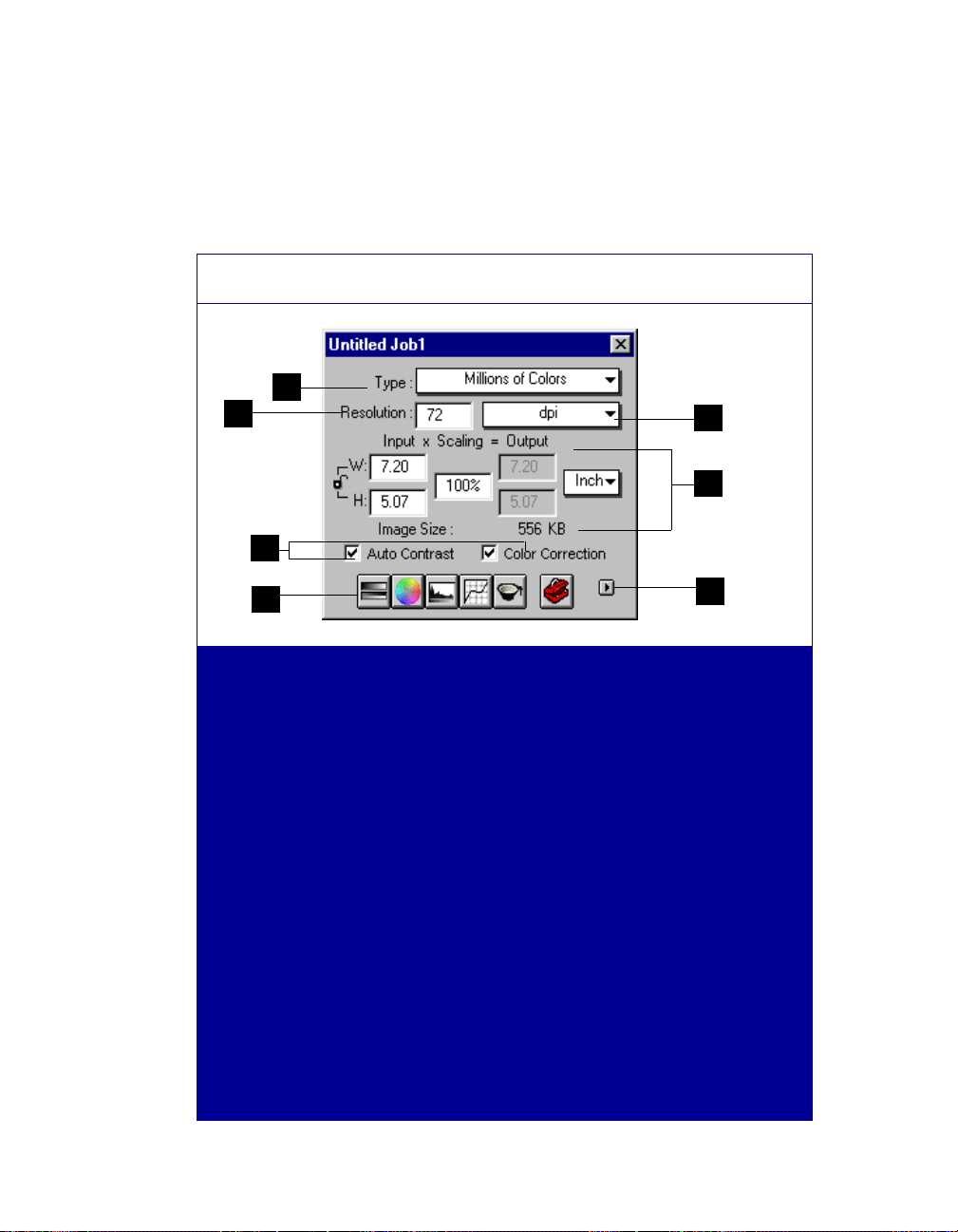
Elements of the Untitled Job1 (Settings) window
1
2
5
3
4
6
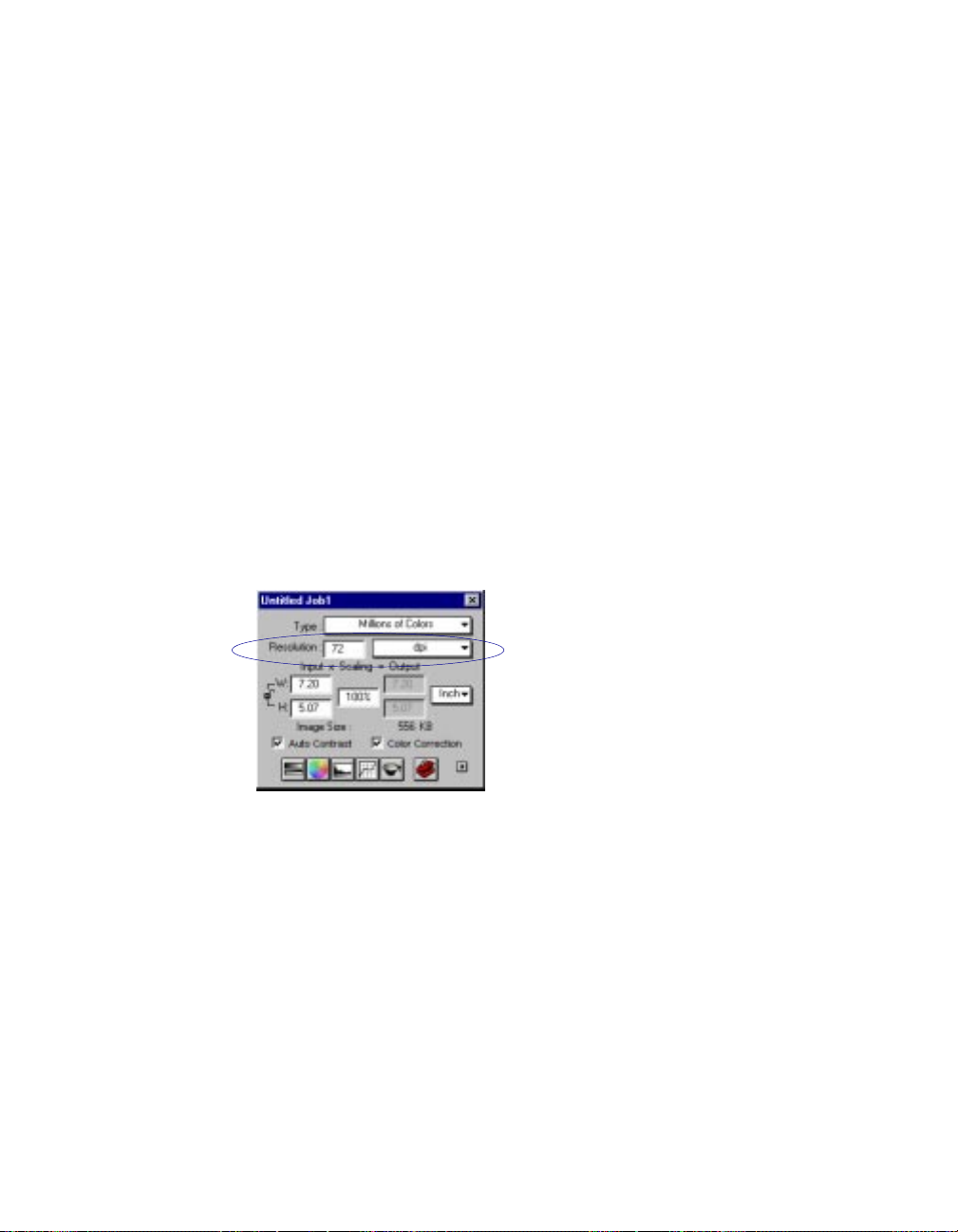
1 The Type menu lets you
select the mode in which
your image will be scanned
and processed.
2 The Resolution edit box
lets you enter a resolution
value in which your image
will be output (not
scanned).
3 The Unit Selection lets
you choose the unit of
measurement for resolution
in either dpi (dots per inch)
or lpi (lines per inch).
4 The Image Dimension
controls include various
parameters for specifying
input width and height,
scaling, output width and
height, and unit of
measurement.
7
5 The Image adjustment
controls let you adjust
images quickly with the
click of a button. These
controls are the Auto button
and Color Correction
button.
6 The Image enhancement
tools let you adjust your
image in many different
ways.
7 The Window Expansion
button reveals the bottom
half of the Settings window,
which includes the various
image-enhancement
controls corresponding to
#6.
34 Microtek Scanner User's Guide (PC version)
Page 40

Output Image Parameters
The Output Image Parameters include the various controls that determine how your
image is scanned and processed. The Output Image Parameters include:
• Type
• Resolution
• Image Dimension controls
Type (Image Type or Scan Mode)
The Type menu determines what your resulting scan will be. It does not refer to the
original image mode. For instance, if you have a color photo but choose 256 grayscale
for the scan mode, the photo is scanned and processed as grayscale.
To use the Type menu:
• From the Type menu select the image type for your final scan. Choose the correct
image type, as the wrong choice will simply create bigger files that won't be of any
use to you. For instance, if you have a grayscale original, do not set image type to
Millions of colors.
• If you select Halftone, choose the halftone screen as well from the submenu. The
image you obtain when you choose Halftone may not look clear in the preview. To
see what it actually looks like, you may need to scan it in. The various halftone
patterns give you an array of effects for your image.
The options
1000's shades of gray
available only for 36-bit scanners
and for some applications (like
Adobe Photoshop).
If your application does not
support these options, do not
select them as your scanned
images may be distorted.
Billions of colors
are
and
35Reference
Page 41
Resolution
Resolution determines the level of detail recorded by the scanner, and is measured in
dots per inch (dpi). The greater the dpi number, the higher the resolution and the resulting file size. Image quality improves with higher resolution, but only up to a certain
point, after which increasing the resolution simply makes file size unmanageable without
yielding any visible improvement to the image. For most purposes, scans up to 300 dpi
are adequate.
Resolution is also related to scaling, or how large or small the image will be scanned
relative to the original. When you change the resolution, the scaling may be affected
slightly if the resolution you selected has no exact equivalent in scaling. (Scaling is
discussed in the next section, Image Dimension controls.)
To set your resolution:
Enter a resolution setting in the Resolution edit box. There is no need to press the Enter
key; typing in a value automatically inputs it into the system. If the value you enter is too
low or too high, the minimum or maximum resolution value is entered for you instead.
Optical Vs. Interpolated Resolution
When dealing with resolution, it's important to distinguish between optical, or true,
resolution, and interpolated resolution, which is resolution enhanced through software.
• Optical resolution is the key factor in determining the sharpness and clarity of an
image.
• Interpolated resolution, or resolution enhanced through software, is useful for
certain tasks, such as scanning line art or enlarging small originals.
36 Microtek Scanner User's Guide (PC version)
Page 42

Choosing the best resolution setting
Scanning at a higher resolution requires more time, memory, and disk space. When
choosing a resolution setting, consider the type of image you're scanning and the
printing method. Printed images have their own resolution, as measured in lines per inch
(lpi), which is distinct from the resolution of electronic images (as measured in dpi).
An easy way to determine the best resolution for your intended output is to find out the
lines per inch (lpi) capability of your output device and multiply it by 1.5 to 2.0.
For instance, to tailor your scanned image to a typical magazine printing press that
prints at 133 lines per inch, multiply 133 x 1.5 or 2.0, which gives 199.5 or 266. In this
case, the optimal resolution setting for your image would then be 200 dpi to 266 dpi
(depending on how high the output quality will be). Lpi varies, depending on the quality
of the printing job. A newspaper uses approximately 85 lpi, magazines from 133 to 150
lpi, and fine art books may go as high as 200 to 300 lpi.
If you're outputting images to a monitor (such as doing multimedia work), you need not
scan images higher than 72 dpi, as monitors are capable of only showing images up to
72 dpi. A higher-resolution image will not be any clearer on the monitor and will simply
create larger files.
When to use high resolution
High resolution is important if you're processing an image through a high-end color
system that carries continuous tone data from the scanner through the final film output.
This is because high resolution can improve the sharpness and clarity of the dots that
make up the image.
When to use interpolated resolution
Interpolated resolution is useful for scanning line art or enlarging small originals.
• For line art: Set the resolution equal to that of your output device. For instance, if
you're producing line art to be printed by a 1200-dpi imagesetter, you can interpolate resolution to up to 1200 dpi for superior results. This will produce smoother
lines and eliminate some of the jaggedness characteristic of line art scans.
• For enlarging small originals: Let's assume that you scan a 1" x 2" photograph at
300 dpi, and that your maximum optical resolution is 300 dpi too. To enlarge the
image to two times the original size without loss of detail, interpolate the resolution
to 600 dpi. This way, the image retains clarity and sharpness even if the print size
was doubled.
37Reference
Page 43
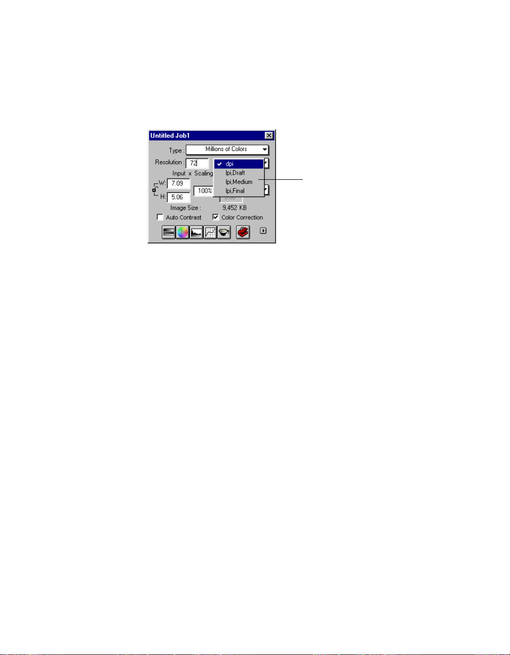
Unit Selection
The unit of measurement for resolution is in dpi (dots per inch) or lpi (lines per inch).
Lpi settings are dimmed if the ruler unit is in pixels.
Choose your unit of
resolution from here
To select your option:
• Choose dpi if you know precisely the resolution you need for your image. For more
details on resolution, see the Basic Concepts chapter.
• Choose lpi Draft to produce resolution that is one times the screen frequency (no
higher than 72 pixels per inch). Draft quality may result in output images that look a
little blurred or indistinct at edges.
• Choose lpi Medium to produce resolution that is one and one-half times the screen
frequency (no higher than 72 pixels per inch).
• Choose lpi Final to produce resolution that is two times the screen frequency.
38 Microtek Scanner User's Guide (PC version)
Page 44

Image Dimension controls
These controls allow you to adjust the various factors that affect the image, including the
width and height of your image when it is first scanned (input), the scaling factor, and
the dimensions of the image when it is finally output.
1
3
2
4
5
1 This is a mathematical formula expressing the relation of the input dimensions to scaling and how
they affect image dimensions when the image is scanned.
• Input width and input height refer to the dimensions of the scan frame that you draw. For
example, if the image on your scanner is 5" x 7" and you draw a scan frame that is 3" x 4",
then your input width will show 3.000 and your input height will show 4.000.
• Output width and output height refer to the dimensions of the image when output to an
output device (such as a monitor or printer).
The input width, input height, output width, and output height are affected by your scaling and
whether or not the Aspect Lock is on. For more details, see the sections
dimensions
2 The Aspect Lock allows you to keep the ratio of the image width and height constant. (For more
details, see the section
3 Scaling lets you create large or small images so that the images don't have to be resized
subsequently, which is usually done in your image-editing software.
4 The Unit of Measurement allows you to select your unit of measure. The options include inch,
centimeter (cm), millimeter (mm), point, and pixel.
and
How to use the Aspect Lock.
How to use the Aspect Lock
in the following pages.)
How to use Input-Output
5 The Size indicates how big the file will be when you accept the dimensions shown in the edit
boxes, together with the resolution setting that you selected. Size is calculated automatically.
To use the Image Dimension Controls:
1 Select the unit of measurement.
2 Enter a value in the applicable edit boxes (width input, height input, scaling, width
output, height output.
39Reference
Page 45

How to use the Input-Output dimensions
The Input-Output dimensions consist of four edit boxes: input width, input height, output
width, and output height. These edit boxes are linked to the use of the Aspect Lock, and
the boxes may or may not be edited depending on whether the Aspect Lock is on or off.
Below are the details.
Input Dimensions
Use the input dimensions to specify your scan frame. If you wish, you can also drag on
the scan frame to whatever size you want, and the dimensions will be reflected in the
input width and height boxes.
The input dimensions can be changed only if your Aspect Lock is off, and this is evident
because only the input dimensions have edit boxes around them.
The output dimensions have no boxes around them, indicating that they cannot be edited
at this point. The output boxes, however, will respond to changes in the input boxes (and
scaling).
Aspect
Lock is off
Output edit boxes
are grayed out
With Aspect Lock off, only input
dimensions can be edited
40 Microtek Scanner User's Guide (PC version)
Page 46

Ouput Dimensions
The output dimensions determine the width and height of your image when output to an
output device such as a monitor or printer. Take note of the following:
• The output dimensions can be changed only if the Aspect Lock is on.
• The output dimensions are calculated dynamically, and the system looks at other
variables such as your resolution and scaling to determine the final output
dimensions. This means that you may specify output dimensions of 5" x 7", but
because of intervening variables, the actual output dimensions may be 4.85" x 6.9"
— which is the closest the system can produce given your other variables.
Aspect
Lock is on
Input edit boxes
are grayed out
With Aspect Lock on, only output
dimensions can be edited
41Reference
Page 47

How to use the Aspect Lock
The Aspect Lock preserves the ratio of the image width and height from input to output.
For instance, if your image is 2 inches wide by 4 inches high, changing it to 1 inch by 2
inches will maintain its aspect ratio. Changing it to, say, 1 inch by 4 inches, however,
will alter its aspect ratio, so that the image will be narrower than the original.
The Aspect Lock is a toggle. Click on it to lock or unlock. The notes below provide
more details on how to use the Aspect Lock.
• If the Aspect Lock is ON: Changing one output edit box (width or height) will
automatically change the other output field, as well as scaling, to preserve the
aspect ratio. With Aspect Lock on, you cannot edit the input dimensions.
Aspect
Lock is on
Changing one output field will change the other.
Note that aspect ratio is preserved (input 2x4;
output 4x8); scaling also changed automatically.
• If the Aspect Lock is OFF: Changing one input edit box (width or height) will NOT
automatically change scaling or the other input field, and aspect ratio can be
changed. With Aspect Lock off, you cannot edit the output dimensions.
Aspect Lock
is off
42 Microtek Scanner User's Guide (PC version)
Changing one input field will not automatically
change the other. Note aspect ratio is not
preserved (input changed from 2x4 in previous
box to 3x4).
Page 48

Scaling
Scaling is the process of creating larger or smaller images in your scanning software so
that you need not resize the images later when they are delivered to your image-editing
program.
In the scanning software, scaling has an inverse relation to resolution: The lower the
resolution, the larger the image can be scaled. At the highest resolution, images can only
be scaled smaller.
T o illustrate the use of scaling: Assume that your input dimensions are 4" x 5":
• If scaling is at 100%, output dimensions will also be 4" x 5".
• If scaling is at 50%, output dimensions will be halved — to 2" x 2.5"
• If scaling is at 200%, output dimensions will be doubled — to 8" x 10".
The above assumes that your resolution is held constant throughout the changes. When you
change resolution and specify a value that has no exact equivalent for scaling, the scaling
may be affected and adjusts itself to the nearest allowed value. For instance, if your resolution
is 100, your scaling becomes 99 (instead of a full 100), because that is the closest scaling
equivalent, given the resolution value.
43Reference
Page 49

Image Adjustment controls
The Image Adjustment controls include the Auto button and the Color Correction
button, located below the Image Dimension Controls.
Auto (Automatic Contrast Control)
The Auto button optimizes the contrast of scanned images by making adjustments to the
Shadow/Midtone/Highlight values.
The Auto setting works by calculating the image settings of the current scan frame and
applying those settings to either lighten or darken an image. Take note of the following:
• If the current scan frame encloses the whole preview image, the Auto setting is
applied to the entire image.
• If the current scan frame encloses only a portion of the preview image, the Auto
setting is applied only to the portion of the image within the current scan frame.
Experiment with the Auto setting and see how it affects your images. The Auto button
will be dimmed if the image type selected in the Type box is "Line Art" or "Halftone".
To use the Auto feature:
1 Click on the Preview button to preview the image.
2 Click on the Scan Frame tool, and draw a scan frame of the area where Auto will be
applied.
3 Click on the Auto button in the Untitled Job1 (Settings) window. The button will
light up, indicating that Auto has been applied.
If you do not like the results obtained by Auto, or if you choose not to use it for
certain images that have Auto enabled, click on the Auto button again to deselect
the feature. A message will appear, asking if you wish to reset the Shadow /
hightlight / midtone values; click Yes. This will return your image to the original.
The Auto button
44 Microtek Scanner User's Guide (PC version)
Page 50

Color Correction / DCR
This tool applies a generic color correction profile to your images to give it accurate,
lifelike color. However, if you have Microtek's DCR color calibration and correction
system installed, the Color Correction button will override the generic color profile and
apply DCR to the image.
A generic color profile is provided with the scanning software to correct the minor color
shifts that occur invariably with scanners. To achieve optimal color correction, however,
you need a true color calibration and correction system like Microtek's DCR, or Dynamic Color Rendition, developed expressly for this purpose.
DCR creates an industry-standard color profile matched to your scanner, so that colors
in your scanned image are adjusted to their optimal levels. DCR comes standard on
certain ScanMaker models and is available as an option on other models. To obtain
DCR, call Microtek Sales at 800-654-4160.
The Color Correction button is turned on by default, but it can be turned off by clicking
on the button again. Color Correction will be dimmed in the following instances:
• If image type is set to billions of colors, any grayscale setting, line art, or halftone.
• If the scan material type chosen (in the Scan Material command, Preferences menu)
is Negative.
The Color
Correction
button
45Reference
Page 51

Image Enhancement Tools
Brightness, Contrast,
and Exposure
Tints
Shadows and Highlights
Curve
Filters
46 Microtek Scanner User's Guide (PC version)
More Options
Page 52

What the Image Enhancement Tools are
The image-enhancement tools are an integral part of ScanWizard, and they let you adjust the
characteristics of your image such as brightness and contrast right from within ScanWizard.
Take note of the following:
• When you click on an image-enhancement tool, a dialog box called the Advanced Image
Enhancer (AIE) appears. The AIE dialog box lets you view changes to image enhancement in real time. The AIE dialog box has two thumbnails — providing you with
"before" and "after versions of an image.
• Although you can use all the image-enhancement tools, you don't need to use every one
of them to achieve a great image. Perhaps all that's needed is a change in the shadows or
gamma curve. Try experimenting with the tools to see which one provides optimal
results.
• The effects of the image-enhancement tools are cumulative. This is important because
the cumulative effects will affect the image in a way that's totally different than if only a
single image-enhancement tool was used. Example: If you increase brightness in an
image (through the Brightness Contrast and Exposure tool) and then modify the gamma
curve of the image (through the Curve tool), the image will have both brightness and
curve changes.
The Advanced Image Enhancer dialog box
The kind of screen
you see is
indicated by the
selected image-
enhancement tool.
Above is the
Brightness
Contrast and
Exposure screen.
Below is the
Filters screen.
Parts common to
all screens
(including vertical
toolbar in right
side of dialog box)
Parts specific to
each screen
47Reference
Page 53

Using the Advanced Image Enhancer dialog box
When you click on any of the image-enhancement tools in the Settings window, the
Advanced Image Enhancer (AIE) dialog box appears. In this box, you can do the
following:
1 This is where you select the scan job to which image enhancement will be applied.
(Note: For definition of a scan job, see the Scan Job section of the Reference.) If you
have multiple scan jobs, you can switch among the various jobs, and the thumbnails
will change accordingly to show the selected scan job.
Switching to a new scan job while using the AIE dialog box will make any
changes to the currently selected scan job permanent. This cannot be undone
even by selecting the Cancel button.
Example: Assume you have two scan jobs, Scan Job 1 and Scan Job 2. If you
applied a filter (through the Filters tool) to Scan Job 1, and then switch to Scan
Job 2, the filter will be applied to Scan Job 1 even though you did not click OK.
To undo the filter, you will need to use the Reset button. See next page on how
to use the action buttons for more details.
2 These are the thumbnails of the image captured by your scanner. The left thumbnail is
the "before" version — which shows the effects of the last saved settings values. The
right thumbnail is the "after" version — which shows the effects of the new settings
added in the AIE.
3 To select another image-enhancement tool, click on any of the buttons displayed in
the vertical toolbar on the right side of the dialog box.
4 Click on an action button to achieve a particular ef fect. (See next page for more details.)
3
Click on any
button here to use
another imageenhancement tool.
The dialog box will
change
accordingly.
48 Microtek Scanner User's Guide (PC version)
Choose your
1
scan job here
Click on a button
4
for an action
Left thumbnail:
2
Before
enhancements
Right thumbnail:
After
enhancements
Page 54

The Action Buttons in the AIE dialog box
The Action buttons in the AIE dialog box (item #4 in preceding illustration) carry out a
specific action. Below are the details.
OK button
Clicking on this button will apply whatever image enhancements you have performed on
the current scan job, and close the AIE dialog box. Clicking OK is not the same as
switching to another scan job (if you have multiple scan jobs). If you switch scan jobs, the
effects are applied to your current scan job, and then the new scan job appears; you do
not exit the AIE dialog box.
Example: If you increased brightness, changed the saturation, and then clicked OK, all the
changes are applied, and you exit the AIE dialog box.
Cancel button
Clicking on this button will cancel out all image-enhancement changes you have made to
the current scan job, and then close the AIE dialog box.
Reset button
Clicking on this button brings up the Reset dialog box, where you can specify which
settings are to be reset, then click Reset or Cancel. If Reset is selected, the settings are
restored to their default values; if Cancel is selected, the operation has no effect.
Select the settings
to be reset, then
click Reset. The
selected settings
are restored to
their default
values.
Example: If you changed shadows / highlights, changed brightness, then clicked on Reset
and chose to reset brightness, the brightness setting of the scan job is restored to its
default; but the altered shadows and highlights remains in effect. If you reset both
shadows/highlights and brightness, then those values are both restored to default.
Revert button
Clicking on this button cancels out the changes you made with the current imageenhancement tool. This means that if you used several tools (and achieved a look that is
the cumulative effect of all the tools), using Revert will cancel the effect of only the current
tool and preserve the effects of the other preceding tools.
Example: If you changed shadows, applied filters, changed brightness, then clicked
Revert, the brightness changes will be cancelled out, but the altered shadows and filters
settings remain in effect.
49Reference
Page 55

Brightness Contrast and Exposure tool
Usage
To change the
brightness,contrast and
exposure setting of the
entire image.
The Brightness, Contrast and Exposure (BCE) tool changes the brightness,
contrast, and exposure setting of the entire image.
Brightness is the balance of light and dark shades in an image, while
contrast is the range between the darkest and lightest shades in the image.
On the other hand, exposure works like the exposure feature in photography, allowing you to change exposure of the image by increasing or
reducing available light to the image. The Exposure control is a scanner
hardware-related feature, and using it correctly can allow more detail to
emerge in an image, especially if it was underexposed.
The goal in using the BCE tool is to get the fullest dynamic range possible
for your image. Because the BCE tool affects the image as a whole, you
can try using the Shadows and Highlights tool instead to get the effects you
want if you find that the BCE tool alters your image too much
Original
Increase brightness
Reduce brightness
50 Microtek Scanner User's Guide (PC version)
Reduce contrastIncrease contrast
Page 56

The BCE screen (for grayscale and color)
1
2
3
4
1 The Brightness control lets you change the brightness setting.
• Too much brightness can make an image look washed out.
• Very low brightness levels can make an image look very dark.
2 The Contrast control lets you change the contrast setting.
• High contrast can make an image look like a photocopy of a picture with little or no
gray shades.
• Low contrast can make an image look dull and flat.
3 Channel lets you change exposure settings for a particular color channel (red, green or
blue).
4 Exposure lets you increase or reduce available light to the image. This can be used to
allow more detail to emerge in an image, especially if it was underexposed.
• More exposure can result in lighter images with more visible detail. The higher the
exposure, the longer it takes to scan the image.
• Less exposure can make an image dark and without detail.
51Reference
Page 57

The BCE screen (for line art)
Threshold
In line art mode, the method for determining how gray levels are converted to black and
white is through the Threshold adjustment control.
The threshold is the dividing line between black and white, with the value 128 (the middle
gray level) as the determining point.
• Gray levels below the threshold are converted to black, resulting in a low-contrast, blackand-white representation of the image.
• Gray levels equal to or above the threshold are converted to white, resulting in a highcontrast, black-and-white representation of the image.
To use the Threshold feature, do either of the following:
• Enter a value in the Threshold edit box; or
• Drag the black triangle above the threshold edit box to the right or left. Moving it to the
right will increase the threshold value, resulting in a higher-contrast image. Moving it to
the left will lower the threshold value, resulting in a lower-contrast image.
52 Microtek Scanner User's Guide (PC version)
Page 58
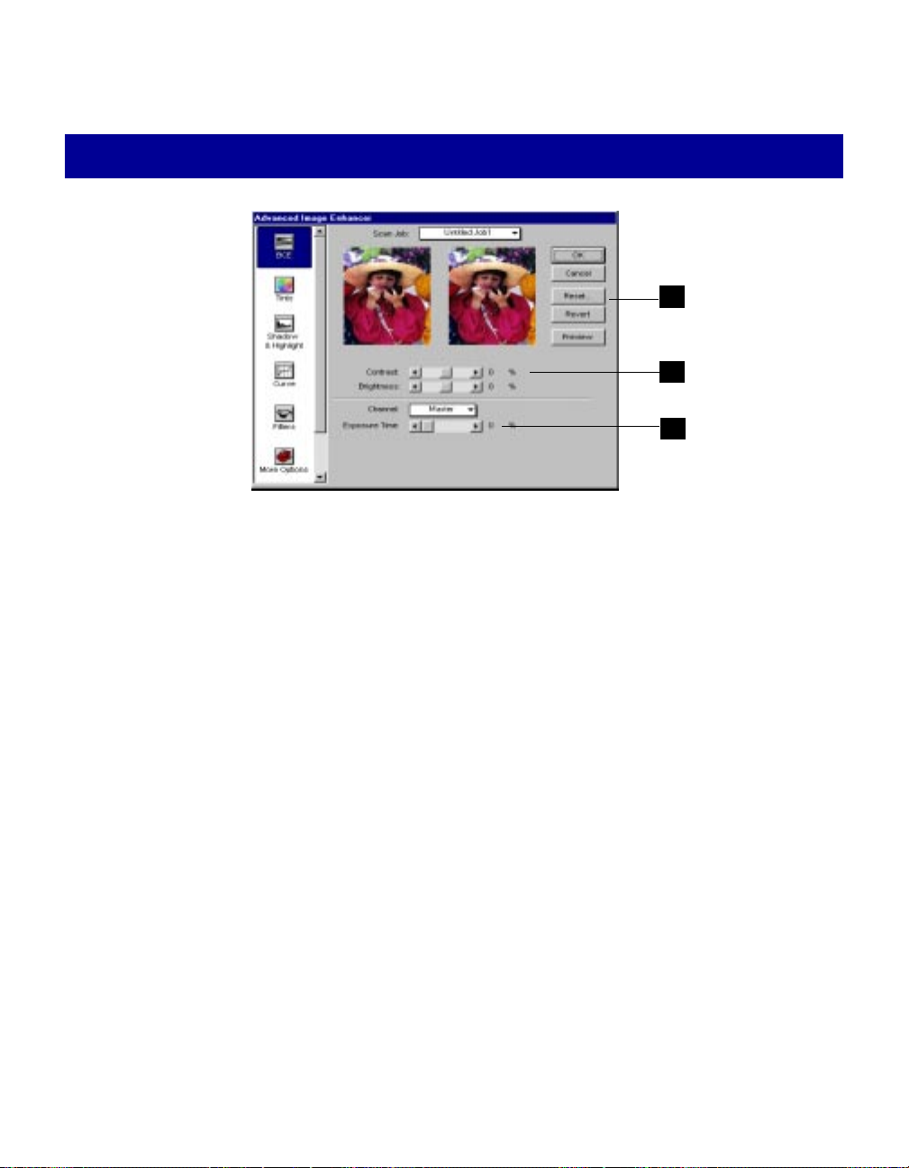
How to use the BCE tool
3
1
2
To change brightness or contrast, choose the Brightness or Contrast control. To change
1
values, drag on the slide bar or click on the arrows at either side of the bar.
2 T o change exposure:
• Click on the Channel box, and select the color channel to be modified.
• Drag on the Exposure slide bar or click on the arrows on either side of the bar.
3 Click on an action button.
• Click OK to accept changes and exit the AIE dialog box.
• Click Cancel to abandon all changes and exit the AIE dialog box.
• Click Reset to restore settings to original default values.
• Click Revert to cancel the effect of the current image-enhancement tool.
For more details, see the section The Action Buttons in the AIE Dialog Box.
53Reference
Page 59
Tints tool
Usage
To change the hue or
saturation of an image.
The Tints tool adjusts the hue or saturation of colors. This tool applies
only to color images and is not available for use with grayscale or blackand-white images.
Hue is the aspect of color that distinguishes one color from another
(whether it is red, green, or blue). In the RGB color model, hue can be
distinguished by its position in the color wheel.
Saturation, on the other hand, refers to the intensity of a color (more red
in an apple, more green in the grass). Increasing saturation can have a
dramatic effect on the colors of an image, but beware of increasing
saturation too much, as it creates artificial-looking, overly bright colors.
The Tints tool is useful when your image has a particular color cast and
you wish to remove the cast to make the image look more natural. The
Tints tool is also related to the Scan Material command in the Preferences
menu. For reflectives or positives, the Tints tool lets you adjust hue and
saturation. For negatives, the Tints tool provides additional controls for
selecting film type and adjusting exposure.
To use the Tints tool:
1 Select the correct scan material for your image in the Scan Material
command in the Preferences menu. The options available to you will
depend on the scanner equipment you're using and certain modules
(like DCR) that need to be installed. For more details, refer to the
Scan Material section.
2 Click on the Tints tool. When the dialog box comes up, make the
adjustments to hue and saturation.
54 Microtek Scanner User's Guide (PC version)
Page 60

The Tints screen
1
2
3
4
1 Color Wheel shows you the position of colors — green is across magenta, and red is
across cyan. By moving the pointer (a small dot) to a place in the color wheel, the hue of
the image is altered. For instance, if you move the pointer towards the green area of the
wheel, the image will acquire a greenish cast.
2, 3 are available only when scan material chosen is negative.
2 Film Type Selection bar allows you to select the type of film you used for your negative.
Choosing the correct film type is important in maintaining image quality, and you should
choose the film type that's indicated on the packaging that came with your film.
The Film Type Selection box provides several choices for you to choose from. If your
type of film is not in the list but a similar film type from the same company is available,
you may choose from one of them. Very often, similar films from the same company use
identical film types. For example, Kodak 135, ASA 100, ASA 200, and ASA 400 are
grouped as the same type — ASA 100.
If your film type is not in the selection list and you cannot find its family group, choose
Generic Negative Film.
3 Exposure Correction bar lets you adjust the exposure of a negative. An overexposed
negative looks dark (with the image itself in the dialog box appearing bright), while an
underexposed negative appears light (with the image itself appearing dark).
• If your film is overexposed (image is too bright), drag the bar to the left; this will make
the image darker.
• If your film is underexposed (image is too dark), drag to the bar to the right; this will
make the image lighter.
4 Saturation bar lets you change the intensity of the hues (colors) in your image. Use Saturation
selectively, because increasing saturation will intensify all hues in the image.
55Reference
Page 61

How to use the Tints tool
5
1
3
4
2
1 To change the hue of an image, move the pointer in the color wheel to its new color position
in the wheel.
2 To change the saturation of an image, drag on the saturation bar. Dragging the slide bar to
the left decreases saturation; dragging it to the right increases saturation.
3, 4 For negatives only:
• To choose the correct film type for your negative, click on the Film Type Selection box
and make your selection. If your film type is not in the list, select Generic Film Type.
• To correct the exposure of a film, use the Exposure Correction bar. To correct
overexposure and make the film darker, drag the triangle to the left. To correct
underexposure and make the film lighter, drag the triangle to the right.
5 Click on an action button.
• Click OK to accept changes and exit the AIE dialog box.
• Click Cancel to abandon all changes and exit the AIE dialog box.
• Click Reset to restore settings to original default values.
• Click Revert to cancel the effect of the current image-enhancement tool.
For more details, see the section The Action Buttons in the AIE Dialog Box.
56 Microtek Scanner User's Guide (PC version)
Page 62
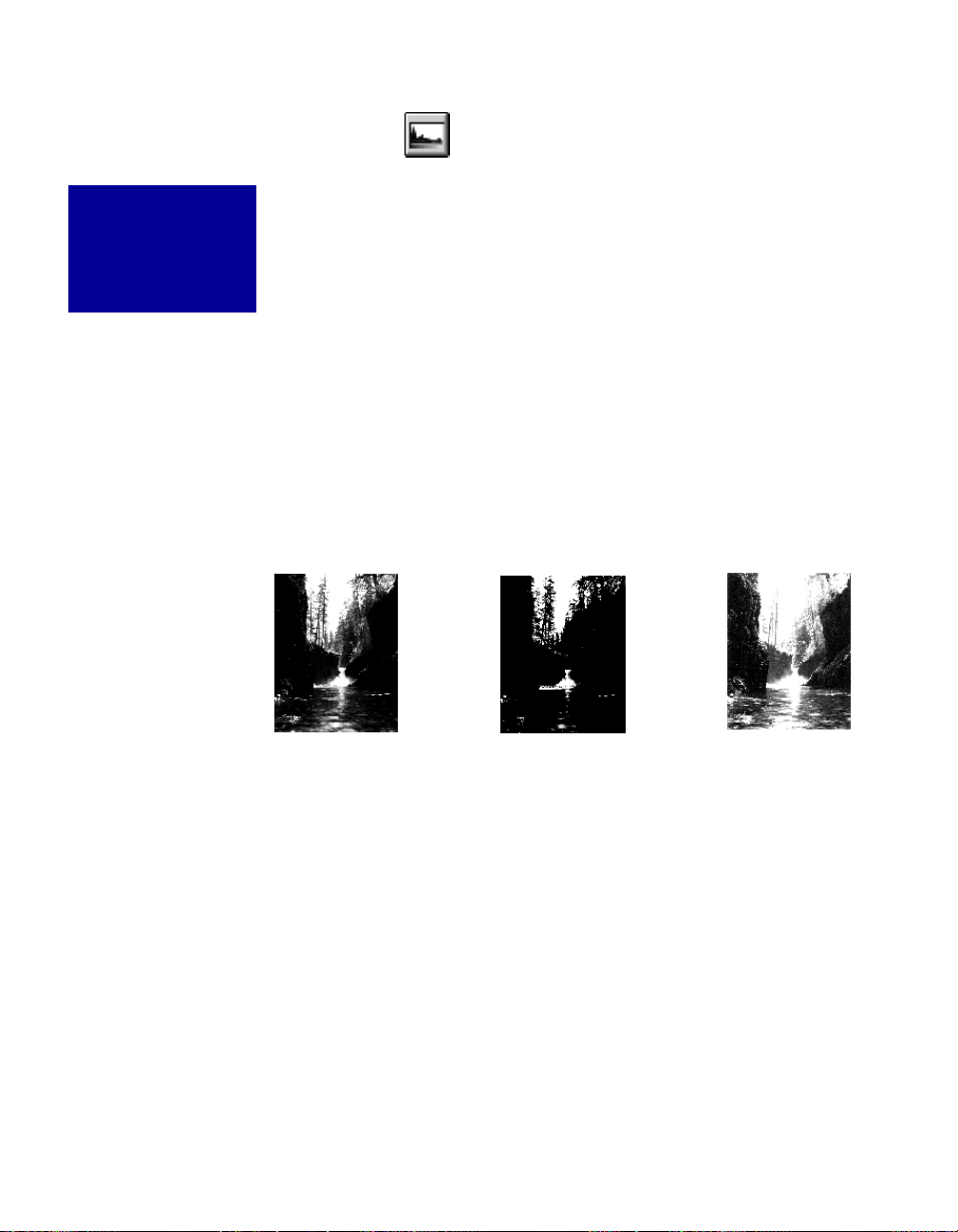
Shadows and Highlights tool
Usage
To change the shadow
and highlight points of
an image.
The Shadows and Highlights tool lets you change the shadow and highlight
points of an image.
By using this tool, you can manipulate shades so that the Shadow point
becomes the new darkest value and the Highlight point becomes the new
lightest value. Shades that are darker than the shadow then become black,
and shades lighter than the highlight become white. For example, if you set
the highlight point to 200, all points in the image with a value greater than
200 will be mapped to a value of 255, since 255 represents the "whitest"
white.
The Shadows and Highlights tool can be used for both grayscale and color
images. If you have a limited range of grays between your lightest and
darkest point, using shadows and highlights will have the effect of extending the range of grays and make more detail in the image visible. This tool
is not available for use with line art or halftone scan modes.
Emphasize shadows
Emphasize highlightsOriginal image
57Reference
Page 63

The Shadows and Highlights screen
6
1
2
3
4 5
1 The Histogram is a graphic representation of how all the pixels in an image are distributed across
brightness and darkness levels. The darkest pixels are at the left; the lightest pixels are at the
right.
• A histogram skewed heavily to the left indicates that the image has many more dark pixels than
light.
• A histogram skewed heavily to the right will indicate a light image as it has more light pixels
than dark.
• The height of the histogram indicates the number of pixels at that point in the histogram.
7
8
2 The Triangles (indicators) below the histogram adjust the Shadow, Midtone, and Highlight
settings.
• The black (left) triangle controls the shadows. Moving this triangle to the right will emphasize
shadows and create a darker image.
• The gray (middle) triangle controls the midtones. Moving it to a value less than 1.0 will have the
effect of darkening the image. Moving it to a value greater than 1.0 will have the effect of
lightening the image.
• The white (right) triangle controls the highlights. Moving this triangle to the left will emphasize
highlights and create a lighter image.
Note: The gray and white triangles will change in color if a color channel (not Master) is selected
in the Channel box.
58 Microtek Scanner User's Guide (PC version)
Page 64

3 Input edit boxes show how pixels are distributed over the 0-to-255 pixel scale.
The input values are related to the position of the indicators along the histogram. For example,
if you move the left triangle in from 0 to 30, the input range becomes 30 to 255, and pixels in
the range of 0 to 30 are then set to 0. In a process called mapping, the new range (30 to 255)
is stretched back to become 0 to 255. The image then becomes darker, since all pixels from 0
to 30 are now mapped to black (whereas 0 to 30 before had subtle gradations from black that
lightened gradually). The same principle applies when you move in the right triangle, and the
highlights in the image become more pronounced.
Moving in any of the triangles above the input boxes will change the values in the boxes. You
can observe how the values in the boxes are affected by moving the triangles, or you can enter
values into the boxes directly. In both cases, the histogram will change accordingly.
4 The Histogram bar shows the distribution of shades from dark to light (left to right). The
distribution of shades changes as you move any of the triangles.
5 Output edit boxes show the 0-to-255 pixel range to where the Input levels are mapped. For
example, if you modified input values to 30 and 255 and then change output values to 0 to
250, the input values of 30 to 255 will be "stretched" to fit the output range of 0 to 250. This
means you have a total of 250 shades (250-0=250).
Unless you have very specific effects in mind, users are advised to leave this feature alone, so
everything is always mapped to 255 shades (255-0). You can experiment with this feature to
see what it does, however, and how it interacts with the input levels.
6 The Original / Enhanced box lets you choose which histogram to see: the original, before the
image was modified; or enhanced, after the image had been modified (with shadows and
highlights or any other tool).
7 The Channel button lets you control the Shadow and Highlight settings for a particular color
channel (red, green or blue) or for the Master channel (red, green, and blue simultaneously).
8 Input / Count / Percent figures provide information about the histogram. The figures will
appear only when the cursor is inside the histogram or if a triangle is being moved.
• Input value indicates the color value of the data displayed in the histogram.
• Count value indicates the number of pixels at the Input value. If Input value is 2 and Count
value is 1300, then there are 1300 pixels in the image at the input value of 2.
• Percent value is the percentage of all pixels in the image where color value is less than or
equal to the input value. If Percent is 15% and Input value is 2, it means that 15% of all
pixels in the image have a value of 2 or less.
59Reference
Page 65

How to read and correct a histogram
A histogram shows how the brightness and
darkness levels are distributed in an image. The
darkest pixels are at the left, and the lightest pixels
are at the right.
An image with good contrast will have a histogram
with vertical lines spread across the scale from left
to right. Here, the histogram is heavily skewed to
the left, where the darkest pixels are, indicating a
dark image.
To change the histogram (and thus the image), use
the three triangles below the histogram.
In the original histogram, the pixels are mostly to
the left where the black triangle is, indicating a
dark image. The range of spread is also broad and
Original image and histogram
Pixels are
concentrated
indicating a
dark image.
flat, with almost no pixels for the midtones and
highlights where the gray and white triangles
are.
In the corrected image, the triangles have been
moved to new locations. The net effect is to
narrow the distribution range of the pixels and
lighten the image.
Generally, the best thing to do is to move the
black and white triangles to the start and end of
the curve.
For example, if your graph starts at about value
20 and ends at 240, then move the black
triangle to 20 and the white triangle to 240.
Move the gray triangle to somewhere in the
middle between the black and white triangle.
here,
Histogram has a broad and flat spread, with almost all
pixels in the shadow range (near the black triangle).
Corrected image and histogram
More highlights visible
More detail shows up
in shadow areas
60 Microtek Scanner User's Guide (PC version)
Triangles moved to
new positions
Page 66
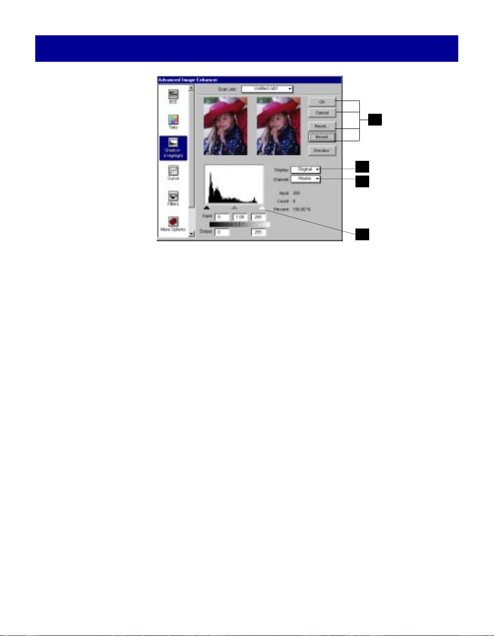
How to use the Shadows and Highlights tool
4
3
1
2
1 Choose the channel in which the histogram will be modified.
• Select Master to modify the histogram in the red, green, and blue color channels
simultaneously.
• Select color channels individually (red, green, blue) to modify the histogram in that particular
channel.
• For grayscale scanners, only the gray channel is available.
2 Move the black, gray, and white triangles to change shadows, midtones, and highlights,
respectively. The values in the input edit boxes will change accordingly.
• To make the image darker, move in the black triangle to the right.
• To make the image lighter, move in the white triangle to the left.
• To change the midtones, move in the gray triangle. If the midtone value is less than 1, the
image becomes darker. If the midtone value is greater than 1, the image becomes lighter.
For more details, see additional information in previous page
.
3 Click on the Display box to view histograms of the original image and the resulting (Enhanced) image.
• Select Original to see the histogram before changes were made to the image.
• Select Enhanced to see the histogram after changes were made to the image.
4 Click on an action button.
• Click OK to accept changes and exit the AIE dialog box.
• Click Cancel to abandon all changes and exit the AIE dialog box.
• Click Reset to restore settings to original default values.
• Click Revert to cancel the effect of the current image-enhancement tool.
For more details, see the section
The Action Buttons in the AIE Dialog Box.
61Reference
Page 67

Curve tool
Usage
To control the midtones, or mid-level
grays, of an image.
How to Read the Curve
Original curve: Straight
The Curve tool lets you control the gamma, which measures the intensity
affecting the mid-level grays (midtones) of an image. Adjusting the gamma lets
you change the values of the middle range of gray tones without dramatically
altering the shadows and highlights.
In many ways, the Curve tool gives you the most control for adjusting an
image's values, but novice users may take some time to master its intricacies.
The Curve tool applies to grayscale and color images and is not available for
use with line art or halftone scan modes.
Modified curve with
diagonal line
points moved up
The Curve shows the relationship of the
brightness changes across the middle pixels
between the resulting image and the original.
When you open the Curves dialog box, the line
on the graph is diagonal because the Input
and Output values are the same.
The x axis of the graph represents the original
brightness values of the pixels, from 0 to 255;
the y axis represents the new brightness
values. Clicking on the diagonal line then plots
a point that can be adjusted.
62 Microtek Scanner User's Guide (PC version)
When the curve is moved up or down, the
relationship between input value and output value
changes accordingly.
• In areas where the curve is moved down, pixels
in that portion of the image are darkened.
• In areas where the curve is moved up, pixels in
that portion of the image are lightened.
Contrast in an image can be seen by the angle of
the line. The steeper the slope, the higher the
contrast. The closer the line is to horizontal, the
lower the contrast.
Page 68

Sample images and their curves
Here, the original curve is
a straight diagonal,
indicating that input and
output values are equal.
Here, points along the curve
have been moved up, so that
pixels are lightened as they are
plotted to new points. The net
effect creates a lighter image.
Here, points along the curve
have been moved down, so that
pixels are darkened as they are
plotted to new points. The net
effect creates a darker image.
63Reference
Page 69

The Curve screen
2
3
4
1
5
1 Curve is a graphic representation of the gamma showing scanner input from dark on the left to
light on the right.
2 Method sets the kind of curve you wish to have. Select from Line, Curve, or Gamma.
Line
Curve
Gamma
3 Channel allows you to choose the color or gray channel in which the gamma will be affected.
4 Input / Output / Zoom:
• Input shows the input value of wherever the cursor is pointing on the horizontal axis of the
curve. In the example above, the cursor is pointing to the middle of the curve, with a value of
136 on the 0-to-255 pixel scale.
• Output shows the output value of of wherever the cursor is pointing on the vertical axis of the
curve. In the example above, the cursor is pointing to the exact middle of the curve, with a
value of 119 on the 0-to-255 pixel scale.
• Zoom indicates the magnification level of the curve box. At 100% zoom, the curve is seen in its
entirety. Using the zoom frame tool (discussed below) to magnifiy the curve will zoom in or
enlarge your view of the curve, resulting in a higher zoom percentage (ex. 200%).
5 Curve Buttons let you modify the curve. The tools are (left to right) the Pointer, Zoom Frame,
and Pane.
64 Microtek Scanner User's Guide (PC version)
Page 70

Using the Curve buttons
The Curve buttons allow you to modify the curve in the Curve dialog box. The buttons are the Pointer,
Zoom Frame, and Pane.
• Use the Pointer button to define points in the curve that will be modified. When you
click on any point in the curve, a control point appears to mark your position. To
Pointer
remove a control point, drag it off the graph.
Original
curve
New control
points
• Use the Zoom Frame button to zoom in on a particular point in the curve. Once the
area is zoomed in, you can then use the pointer button to define new points for more
Zoom
Frame
precision. This is particularly useful for working with 12-bit images, as more detail can
be seen in such images. The zoom level can be seen in the Zoom column (item #4 in
preceding page).
• Use the Pane button to scroll through the curve if the curve has been zoomed in. The
Pane button can be used only if the curve has been zoomed in with the Zoom Frame
Pane
button (above). Otherwise, the Pane button will be dimmed.
65Reference
Page 71

How to use the Curve tool
5
2
1
4
3
6
1 Choose the channel in which the curve will be modified.
• Select Master to modify gamma in the red, green, and blue color channels of the image
simultaneously.
• Select color channels individually (red, green, blue) to modify gamma in that particular color
channel.
• For grayscale scanners, only the gray channel is available.
2 Choose the Method in which the curve will be modified; select from Line, Curve, or Gamma.
There is no difference in the method you select, and the choices are provided to give you more
flexibility in adjusting the curve.
3 Choose a Curve button; select from Pointer, Zoom Frame, or Pane. (See previous section
a curve button
for more details.)
Using
4 Click on the curve to define the points where the curve will be modified. You can then either raise
or lower the curve at that point and see changes to the image accordingly.
5 Click on an action button.
• Click OK to accept changes and exit the AIE dialog box.
• Click Cancel to abandon all changes and exit the AIE dialog box.
• Click Reset to restore settings to original default values.
• Click Revert to cancel the effect of the current image-enhancement tool.
For more details, see the section
The Action Buttons in the AIE Dialog Box
.
6 To save a curve, click on the Save button. A dialog box will appear.
• Save the curve in either Microtek or Photoshop format. The Microtek format allows you to have
as many as 64 control points in the curve for more precision; Photoshop allows a maximum of
19.
• Choose the Channel. Select All if your channel (in #1) is Master; select Current if you selected
one of the three color channels (red, green or blue).
To use a previously saved gamma curve for another image, click on the Load button, then
specify the curve to be loaded. Photoshop-saved curves can be loaded.
66 Microtek Scanner User's Guide (PC version)
Page 72

Filters tool
Usage
To create special
effects for images.
The image you
obtain in the
preview when you
use the Filters tool
may differ from the
way the image will
appear when you
scan it in. This
depends on your
resolution, and the
higher the setting,
the less obvious
certain filters (like
Blur) will have.
The Filters tool lets you apply or create special effects to your images. This tool
is disabled when your image type is set to billions of colors, 1,000 shades of
gray (grayscale), line art, and halftone.
The filters include Blur and Blur More, Sharpen and Sharpen More, Edge
Enhancement, Emboss, and Unsharp Mask.
To use the filters:
1 In the Advanced Image Enhancer (AIE) dialog box, select the filter to be
used (choose None if no filter is desired).
2 To preview filters and see their effects immediately, click on this box.
3 Click on an action button.
• Click OK to accept changes and exit the AIE dialog box.
• Click Cancel to abandon all changes and exit the AIE dialog box.
• Click Reset to restore settings to original default values.
• Click Revert to cancel the effect of the current image-enhancement tool.
For more details, see the section The Action Buttons of the AIE Dialog Box.
3
1
2
67Reference
Page 73

Blur Filters
The Blur filters eliminate noise in the parts of the image where significant color transitions occur. The Blur filters decrease the contrast between adjacent pixels, making the
image appear hazy and out of focus.
• Blur smooths out the transitions by lightening pixels next to the hard edges of defined
lines and shaded areas.
• Blur More produces an effect three or four times stronger than Blur.
Original
Sharpen Filters
Blur
Blur More
The Sharpen filters do the opposite of the Blur filters and increase the contrast of
adjacent pixels, making images appear sharper and more focused.
Both Sharpen and Sharpen More filters improve clarity. The Sharpen More filter has a
stronger sharpening effect than the Sharpen filter.
Original
Sharpen
Sharpen More
68 Microtek Scanner User's Guide (PC version)
Page 74

Edge Enhancement filter
The Edge Enhancement filter gives greater contrast to edges. The filters can do this
because edges are usually areas in an image where gray or color levels change abruptly.
Original
Emboss filter
Edge Enhancement
The Emboss filter makes a selection appear raised or stamped by suppressing the color
within the selection and then tracing its edges with black.
Original Emboss
69Reference
Page 75
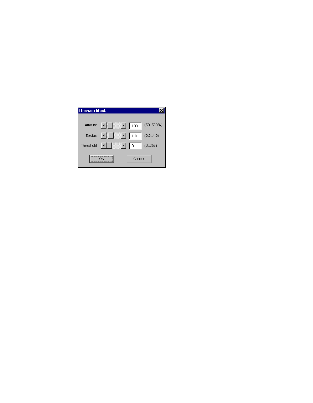
Unsharp Mask
The Unsharp Mask filter adjusts the contrast of edge detail and creates the illusion of
more image sharpness. This filter can be useful for refocusing an image that has become
blurry from interpolation or scanning.
To use Unsharp Mask:
1 Choose Unsharp Mask from the Filters menu. The Unsharp Mask dialog box
appears.
2 Enter a value in the Amount box to specify the percentage of the filter's effect. The
higher the percentage, the stronger the effect of the filter.
3 Enter the Radius value in pixels. The radius determines the depth of pixels that will
be affected at the edge.
• With a high value, more of the pixels surrounding the edge pixels are sharpened.
• With a low value, only the edges are sharpened.
4 Enter a value in the Threshold box.
This option allows you to specify a tolerance range to prevent overall sharpening
that might generate noise or cause other unexpected results.
The Threshold defines the required range of contrast between adjacent pixels before
sharpening is applied to an edge. A lower value produces a more pronounced effect.
70 Microtek Scanner User's Guide (PC version)
Page 76

More Options tool
Usage
For additonal controls
in adjusting your
scanner and image.
The More Options tool provides you with additional scanner and image
controls. These controls include:
• Descreen
• Scan Quality
• Gray Scan CCD Filter
• Using the linear gamma curve
To use the controls in the More Options tool:
1 In the Advanced Image Enhancer (AIE) dialog box, click on the More
Options tool.
2 When the More Options dialog box appears (shown below), select the
particular control to be modified and its option, then click OK.
Select the control to
be modified and its
particular option.
71Reference
Page 77
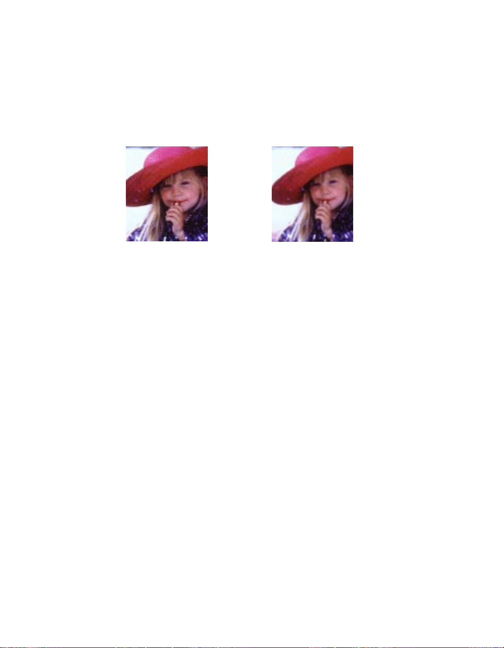
Descreen
Descreen allows you to remove moiré patterns in images. A moiré is an undesirable
pattern in printing that results from incorrect screen angles of overprinting halftones.
Moirés usually result when you scan images taken directly from a magazine (instead of
scanning a continuous glossy photographic original or a transparency).
Before Descreen
After Descreen
To use Descreen:
1 Choose the correct Descreen option.
• Choose Newspaper if the original image has a coarse dot pattern (like images in a
newspaper).
• Choose Magazine for images with a finer dot pattern.
• Choose Art Magazine for images with near-photographic quality with a very tight
dot pattern.
2 Remeber to reset the Descreen option to None after using the feature. Leaving the
Descreen feature on will slow down your future scans, in some instances significantly especially if you're scanning a big file.
72 Microtek Scanner User's Guide (PC version)
Page 78

Scan Quality
This option allows you to select the quality of your scans.
• Choose Draft if you're outputting images as drafts. This option speeds up the
scanning process, but the image may be a little coarse (compared to the Final
option).
• Choose Final if you wish to have a scanned image of better quality. This option,
however, is slower than Draft.
Gray Scan CCD Filter
This option allows you to select a particular color channel when scanning grayscale
images and is useful for obtaining certain effects. When scanning grayscale images,
one of the color channels of the CCD is usually used for scanning; this could be the
red, green, or blue color channel.
Use Linear Gamma Curve
This control allows the scanning software to read only raw image data, so that no color
adjustment (not even the generic color correction profile) is applied to your image
when it is scanned.
This control is helpful for professional graphic designers who wish to create very
specific effects and are thoroughly familiar with the scanning process. If you are not
familiar with this feature, leave this option turned off.
73Reference
Page 79
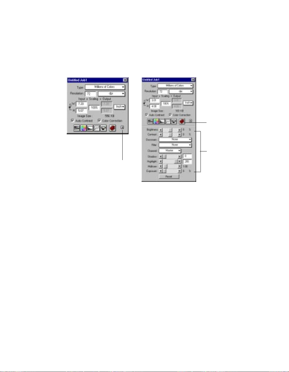
The Window Expansion button
The Window Expansion button lets you expand the Untitled Job1 (Settings) window to its
full size, with the bottom half of the window revealing the image-enhancement controls.
Image
enhancement
tools
Untitled Job1
window before
expansion
Click here
to expand
window
Untitled Job1 window
after expansion
Image
enhancement
controls
When the bottom half of the Untitled Job1 window is open, you can use the imageenhancement functions directly by dragging on the slide bars for each control. This is like
clicking on the image-enhancement button, which takes you to a dialog box where you
can change the controls.
Using the slide bars to adjust images may be faster, but using the image-enhancement
buttons gives you greater control over adjusting images and shows you "before-and-after"
images in a dialog box.
To close the bottom half of the window, click on the Window Expansion button again.
74 Microtek Scanner User's Guide (PC version)
Page 80

The Information Window
The Information window provides information on the cursor and the preview image.
It also allows you to change zoom levels directly, in much the same way like using
the Magnifying Lens tool in the Preview window.
The Information window is a "floating window" and does not appear when you start
up the scanning software. To display the information window, click on the Show Info
window command in the View menu (in the Preview window).
Elements of the Information window
The Zoom Level Display shows the magnification levels
1
possible — from 100% to a maximum 800% view.
The Cursor Locator shows where the cursor is on the
2
coordinates along the x (horizontal) and y (vertical) axis,
based on the unit of measurement selected for the rulers.
The Color Meter Display indicates the values of the red,
3
green, and blue (RGB) color channels of that part of the
image to where the cursor is pointing. The numbers
represent the values in the 0-to-255 pixel range.
The Sample Size button lets you choose how extensively
4
the color information will be read — whether it will apply to a
single pixel or an averaged area.
The Pixel Display shows the pixel and color information of
5
the image part where the cursor is resting.
75Reference
Page 81

Using the Zoom Level Display
The Zoom Level Display magnifies your view of an image, much like the Magnifying
Lens tool in the Preview Window.
The magnification factor in both Zoom Level Display and the Magnifying Lens tool is
by a factor of 2. Thus, the magnification levels increase from 100% to 200%, to 400%,
to 800% and to the maximum 1600%.
To use the Zoom Level Display:
Click on the Zoom Level box. From the drop-down menu that appears, select your zoom
or magnification level.
Click here to
display the dropdown menu, and
then select your
zoom level.
Using the Cursor Locator
The Cursor Locator shows you where the
cursor is on the x (horizontal) and y
(vertical) coordinates of the axis. This
feature is useful for operations that require
very precise measurements and alignment.
76 Microtek Scanner User's Guide (PC version)
Cursor
Locator
Page 82

Using the Color Meter Display
The Color Meter Display is useful if you wish to adjust the shadow and highlight points
of an image.
As you pass over a point in the image, the Color Meter Display will show the appropriate
RGB values of that point in the image. The significance of the numbers is explained
below.
• There are two numbers shown in the Color Meter Display. The first number represents the raw color data taken by the scanner; the second number represents the
resulting value after color correction or image enhancement is applied to the image.
• The values can be anywhere from 0 to 255, with 0 as the black point, 255 as pure
white, and all other values in between corresponding to shades from black to white.
• The values as a whole represent color information for the sample size selected in the
Sample Size button (discussed below). For instance, if you chose 3 x 3 as your
sample size and your R value reads 23, that shows your red value of 23 is the
average of a 3-pixel by 3-pixel area.
The numbers in the Color
Meter Display represent
color information.
The numbers can be from
0 to 255, with 0 as the
black point, 255 as white,
and all values in between
corresponding to shades
from black to white.
Pixel-value information is useful especially if you are making color corrections based on
color values. Knowing this, you can modify the shadow and highlight points of an
image, then come back to the same point in the image, and verify through the Color
Meter Display that the RGB values have indeed changed.
The Color Meter Display can also be used in conjunction with the Color Picker tool. For
more details, see the Color Picker topic in the Preview Window section of the Reference.
77Reference
Page 83

Using the Sample Size button
The Sample Size button provides options for choosing how extensively the color
information will be read — whether the color information will apply to a pixel, a 2-pixel
by 2-pixel area, or a wider expanse (maximum 5-pixel by 5-pixel area).
When you click on the Sample Size button, the drop-down menu below appears:
Determines how the numbers in
the Color Meter Display are
shown — in absolute values or
in percentages
Determines the size of the
sampling area
Value and Percent
• If you choose Value, the numbers in the Color Meter Display represent the values in
the 0-to-255 pixel scale. For instance, an R value of 23 indicates that the sampling size
selected has a red color value of 23. Value is calculated by multiplying the percentage
by the constant 255 (value = 255 x percent).
• If you choose Percent, the numbers represent the percentage of the maximum intensity
of the pixel. For instance, a G value of 35% indicates that the sampling size selected
has a green color value to be 35 percent intense (out of 100 percent). Percent is
calculated by dividing the constant 255 by the value (percent = 255 ÷ value).
Numbers
here are
in
Values
78 Microtek Scanner User's Guide (PC version)
Numbers
here are in
Percentages
Page 84

Sample Size Options
This determines the expanse of color information to be made available. For instance, if
you choose 5 x 5 as your sample area, this means your RGB values will represent color
information for a 5-pixel by 5-pixel area. If you choose 1 x 1, the color information
pertains to a single pixel — the one in the middle of the Pixel Display.
The 1 x 1 sample size means
the RGB numbers represent the
color value of a single pixel —
the one in the middle of the
Pixel Display.
The 5 x 5 sample size means
the RGB numbers represent
the average value of a 5-pixel
by 5-pixel area. This would
include the whole of the Pixel
Display (which is 5 pixels long
and 5 pixels wide).
Pixel
Display
Using the Pixel Display
The Pixel Display helps you see how color pixels are organized and distributed. The
display can then help you make an informed judgment on how best to modify image
characteristics such as shadows and highlights, and also allow you to verify any changes
that are made.
79Reference
Page 85

The Scan Job Window
The Scan Job window is an important feature of ScanWizard and provides several key
functions in processing your scans.
A scan job is simply a task that you designate the scanner to process and scan. For
instance, when you first preview an image, the image as a whole has its own parameters
(its own brightness and contrast setting, resolution, etc.). The whole image can be treated
as one scan job.
From that one image, you can designate several other scan jobs. For instance, you could
select a portion of the image and assign a set of parameters to it (color mode, 300 dpi
resolution). That would constitute a second scan job. If you select yet another portion of
the image and give it different settings (grayscale mode, 100 dpi), that will make up a
third scan job.
The above example makes use of one single image to create three different scan jobs. By
the same token, you can use three different images and create three scan jobs.
The number of scan jobs is indicated by the number of titles in the Scan Job window.
Scan jobs marked with a check are the ones designated to be scanned, and the jobs are
scanned in the order that they appear in the window.
Elements of the Scan Job window
1
2
80 Microtek Scanner User's Guide (PC version)
1 The Title area shows the number of
jobs that have been created. In this
example, there are two scan jobs.
Check marks indicate which job or jobs
are to be scanned; a dot before the
title indicates the current scan job. To
rename a scan job, double click on the
title and type over a new name.
2 The function buttons allow you to
create or manipulate the settings for a
scan job. These buttons include the
Up and Down position arrows;
Duplicate button; New button; Add
button; Save button; Delete button;
and Check button. See next page for
more details.
Page 86

How to read the Scan Job window
1
2
1 The example above shows three scan jobs (three different scan frames).
• The first scan job, Untitled Job1, is a color image, as denoted by a color icon
right beside the title.
• The second scan job, Untitled Job2, is a grayscale image, as denoted by a
grayscale icon beside the title.
• The third scan job, Untitled Job2-1, is a duplicate of the second scan job.
2 The current scan job is the first scan job, as it is highlighted.
3 All three scan jobs will be scanned, as each is marked with a check. To change the
order in which the jobs will be scanned, use the Up and Down position arrows to
change the sequence of the titles.
Rrelation between the Scan Job and Untilted Job (Settings) window
Throughout this chapter, the Settings window has been called the Untitled
Job1 window — and that is because the assumption was there was only
one Scan Job at the time.
If you have multiple scan jobs, however, selecting another scan job will
cause the settings of that scan job to be reflected in the Settings window
as well. The title of that window will then be Untitled Job 2, 3, 4 — as the
case may be.
81Reference
Page 87

New button
The New button creates a new scan job, which will have default settings. This feature
allows you to create as many scan jobs as you wish, and each scan job can then have its
own settings.
In the following example, we will use a single image and then divide it into two parts:
the left half of the image will comprise one scan job and will be in color; the other half
of the image will make up the second scan job and will be in grayscale.
To use the New button:
1 Click on the Preview button to see a preliminary view of the image.
2 When the preview image appears, draw a scan frame that covers the left half of the
image. At this time, your scan job area shows the title of the current scan job
(Untitled Job1). Make sure the image type selected (in the Untitled Job1 or Settings
window) for this scan job is Millions of colors.
Scan frame around
left half of image. This
corresponds to the
current scan job in
Scan Job window.
82 Microtek Scanner User's Guide (PC version)
Page 88

3 Click on the New button in the Scan Job window; a new scan job is created called
Untitled Job2. At the same time, a new scan frame will appear in the preview image.
To rename the scan job, double-click on the title and give it a new name..
Two titles now
appear in the Scan
Job window.
4 Move the second scan frame to somewhere around the right half of the image. In this
case, confine the second scan frame to the upper right half, leaving the lower right
half of the image free. The reason why will become apparent in the next step.
Draw second scan
frame around upper
right half of image.
83Reference
Page 89

5 With the second scan job (Untitled Job2) highlighted in the Scan Job window, go to
the Untitled Job2 or Settings window, then choose 256 shades of gray in the Type
box. Next, go to the Preferences menu in the Preview window and enable the
Smoked Glass Background command.
You will now see the following:
• The second scan job (the upper right half of your image) is in grayscale.
• The lower right half of the image (the part not included in any scan frame) is
hidden behind the smoked glass background. The smoked glass command is not
essential for doing a scan job, but it helps you distinguish scan frames more easily.
Upper right half of
image (second
Left half of
image is first
scan job
scan job) is in
grayscale.
Lower half of image is
not in any scan frame
6 To see how the scan jobs relate to the titles in the Scan Job window, try this.
• Click on the first scan job title. The scan job that becomes active will be the left
half of the image (in color). In the Scan job window, the title will have a dot in
front of it, indicating that it is the current scan job.
• Click on the second title, and the second scan job is activated (upper right-hand
part of image, in grayscale). The dot will now appear in front of the second title
because it will be the current scan job.
7 To designate the scan job to be processed and scanned, select the scan job and click
on the Check button. The checked scan job(s) will then be scanned in the order that
they appear in the Scan Job window, and they will be delivered separately to your
image-editing software.
84 Microtek Scanner User's Guide (PC version)
Page 90

More Applications
The above example shows how to use the New button to create different scan jobs.
While the example makes use of creating two scan jobs from a single image, with each
scan job being a different image type, you can use the same principle in different
applications.
For instance, you can:
• Create two or more scan jobs from a single image. The scan jobs may be the same
image type (all color or all grayscale), but each job could have different brightness
and contrast settings, resolution, etc.
• Create different scan jobs from multiple images. Instead of one, you can have two
or more images and designate each image as a separate scan job. Image 1 could be
color, image 2 could be grayscale, and image 3 could be line art. When the three
scan jobs are scanned, each is delivered into its own file.
When you have multiple scan jobs and designate all of them for scanning (all scan jobs
are checked), each job will be scanned once you activate scanning, and each job is
delivered to its own file in your image-editing software.
85Reference
Page 91

Duplicate button
The Duplicate button lets you duplicate the settings of a scan job. This function is
especially helpful if you have created optimal settings for a scan job and wish to use
these settings as a template for other scan jobs. This saves time, as you don't have to
create the settings repeatedly for every scan job you make.
Before using Duplicate, it is helpful to turn on the Smoked Glass Background feature.
This will allow you to see clearly the effects of duplication.
To use the Duplicate button:
1 Click on the Preview button to see a preliminary view of the image. To show the
principle of duplication clearly, choose image type (in the Settings window) as
Millions of colors. Also, turn on the Smoked Glass Background feature (in the
Preferences menu of the Preview window). Draw a scan frame around a part of an
image. This is your current scan job.
2 Draw a scan frame around a part of the image. This is your current scan job.
Draw scan
frame around
image part. This
is the current
scan job.
Shortcut to creating
duplicate scan jobs:
Hold down the Shift key
and drag the mouse. A
duplicate scan job is
created based on the
current scan job, and a
duplicate title is added in
the Scan Job window.
3 To see the effects of duplication clearly in the steps that follow, do this as an
experiment. Set the image type of the current scan job to 256 Grayscale.
4 Click on the Dup button in the Scan Job window . Draw another scan frame around a
different part of the image; this is your duplicate scan job. You will see that the duplicate
scan job will also be in grayscale, as it shares the settings of the current scan job. In the
Scan Job window, there will be two titles, and the duplicate scan job is the one with a
number and dash to it (ex. Untitled Job 2-1).
86 Microtek Scanner User's Guide (PC version)
Page 92

Save button
The Save button lets you save the settings in a scan job to a scan job template that can be
used for future scan jobs. To use the Save button:
1 Click on the Save button.
2 When a dialog box appears, give a name to the scan job template to be saved, then
click OK.
Add button
The Add button lets you add a scan job from a scan job template saved previously. To use
the Add button:
1 Click on the Add button.
2 When a dialog box appears, specify the name of the scan job template to be added,
then click Add. To close the dialog box, click Close.
Check button
The Check button allows you to select the scan jobs to be scanned. When you then click
on the Scan button to start scanning, the scan jobs marked by a check are the ones that
will be scanned. The Check button is a toggle. To use the Check button:
1 In the Title area of the Scan Job window, select the scan job to be scanned.
2 Click on the Check button. A check will appear next to the selected scan job.
3 To uncheck a selection, select the scan job to be unchecked, and click on the Check
button again. The scan job will be unchecked, and the scan job will not be scanned
when you click on the Scan button.
Delete button
The Delete button lets you delete a scan job from the list. To use the Delete button:
1 In the Title area of the Scan Job window, select the scan job to be deleted.
2 Click on the Del button. The scan job is deleted.
87Reference
Page 93

Up/Down Position Arrows
The Up/Down position arrows allow you to change the sequence in which jobs are
scanned through changing the order of the scan jobs in the Title area. To use the Up/
Down position arrows:
1 In the Title area of the Scan Job window, select the scan job to be moved up or
down.
2 Click on the Up or Down arrow to change the order of the scan job in the list. When
you start scanning, the scan jobs will be processed and scanned in the order that they
appear in the Scan Job window (i.e., the first scan job is scanned first; the second
scan job is scanned second, etc.).
88 Microtek Scanner User's Guide (PC version)
 Loading...