

Microtek SCANMAKER 3700, SCANMAKER 3750i, SCANMAKER 4600, SCANMAKER 4700, SCANMAKER 5600 Replacement Instructions
...Page 1
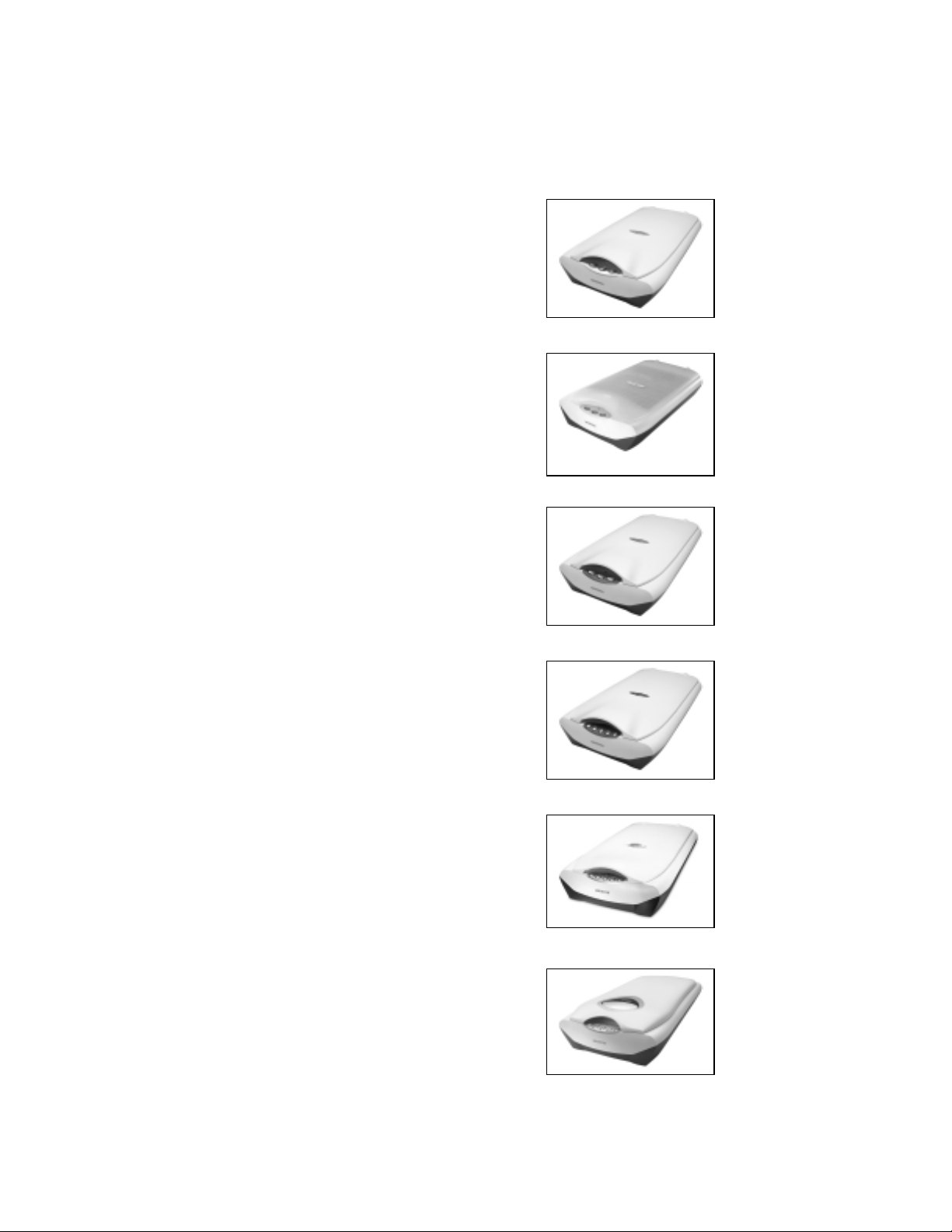
Lamp Replacement Instructions For:
SCANMAKER 3700
SCANMAKER 3750i
SCANMAKER 4600
SCANMAKER 4700
SCANMAKER 5600
SCANMAKER 5700
Last Updated 1-22-03 1 of 14 MI-0047-013
Revision 1.0
Page 2

A scanner is a precision optical instrument and changing a
lamp is not like changing a household bulb. We do not
recommend that you replace the scanner lamp on your own
because of potential problems that may come up during the
lamp replacement. Technical Support personnel are not
trained in repair; therefore, if you get in trouble, assistance
in replacing the lamp is not available. Proceed at your
own risk!
Tools Needed:
Phillips Screw Driver
Flat Screw Driver or small pry bar
Needle Nose Pliers
Recommended Materials
Glass Cleaning Cloth
Canned Air
:
Last Updated 1-22-03 2 of 14 MI-0047-013
Revision 1.0
Page 3
Selecting A Work Area
It is important that you begin by planning where you will lay your disassembled parts.
Locate an area with a workbench, table or desk with plenty of space.
Make sure that th e area is clear of any other parts from other devices, as the many
screws and nuts can be easily confused.
We recommend that you lay a sheet or tablecloth on the surface you will be
working on. This will prevent tools, parts and screws from sliding around and
falling to the floor. This will also prevent any parts from scratching the surface of
the work area.
Before You Start
In order to prevent any short-circuiting of the electronic chips on the scanners
motherboard, it is very important that you ground yourself by simply touching the
metal part or parts of your PC.
Make sure that the area you touch on your PC is bare metal and not coated with paint or
plastic. This will allow for any static electricity to discharge from your body.
Note: Make sure that the scanner power cable is disconnected from the back of
the scanner at this point.
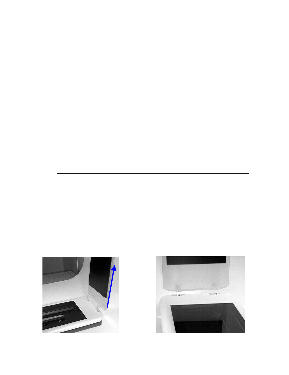
Removing the Scanner Lid
Removing the scanner lid is probably the easiest part of these instructions. Simply open
the scanner lid to a 90-degree angle and lift upward to remove the lid. (See illustration
below.)
Last Updated 1-22-03 3 of 14 MI-0047-013
Revision 1.0
Page 4
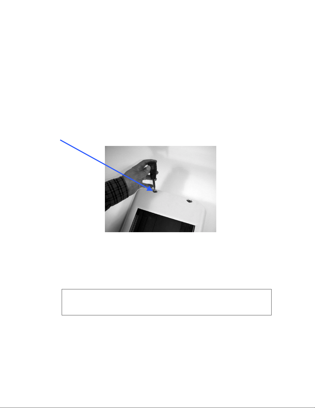
Removing the Scanner Upper Outer Housing
Most of our scanner models have two phillips head screws holding down the
upper housing.
You will notice the phillips screws inside of the receptacles where the scanner lid posts
(hinges) are inserted. (See illustration below.)
1. Remove the Phillips head screws inside of the receptacles where the sc anners lid posts
(hinges) were inserted.
Note: Do not use screwdrivers with magnetic or magnetized tips.
Using magnetized tools around the scanners circuit boards may
damage the circuitry, therefore rendering your scanner useless.
Last Updated 1-22-03 4 of 14 MI-0047-013
Revision 1.0
Page 5
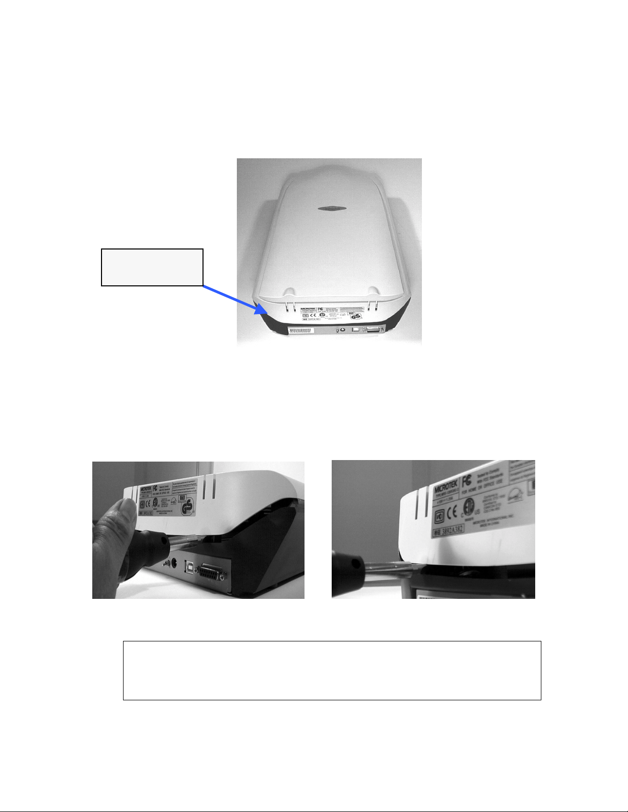
2. You will need to pry open the scanners upper housing. In order to do this without
damaging the scanner we will need a flat head screw driver or a very small pry bar.
Position the front of the scanner facing away from you on the workbench. (See
illustration below.)
Back of the
Scanner
3. Take your flat head screw driver or small pry bar and locate the area immediately
below the lid hinge receptacles. Take your flat head screwdriver and insert it between the
upper and lower housing. (See illustration below.)
Warning: Make sure to select an area where the scanner’s motherboard is not in
the way when you insert the screwdriver or pry bar. If you insert your prying tool
into the motherboard of the scanner you may damage the circuitry, rendering the
scanner useless.
Last Updated 1-22-03 5 of 14 MI-0047-013
Revision 1.0
Page 6

4. Once the flat head screwdriver has been inserted between the upper and lower
housing, rotate the screwdriver or pry bar clo ckwise and counter clock wise in order to
pry open or separate the upper scanner housing from the lower scanner housing.
Note: A good indication that this has happened is that you will here a clicking or
snapping sound as the interior plastic clips are released by the force being used
to pry the scanners upper housing with the screwdriver or pry bar.
5. Once the scanner’s upper housing has been released lift the scanner’s upper housing (at
the rear of the scanner) upward about 1 to 2 inches. (See illustration below.)
This will allow the scanner’s upper housing to clear the two plastic posts at the rear of the
scanner. Then simply pull the upper housing forward or towards you about an inch. Then
lift the upper housing upward to remove. See illustration below:
Plastic Post
Last Updated 1-22-03 6 of 14 MI-0047-013
Revision 1.0
Page 7

Removing The Scanner Lamp Assembly
1. Drag the scanner carriage to the c enter of the scanner as it off ers more room to work
and maneuver. (See illustration below.)
Scanner Carriage
2. Remove the carriage shaft bar guide. You ca n easily achieve this b y locating the clip
post towards the front of the scanner. Pull the metal shaft upward until it dislodges from
the clip post. Then simply remove the metal shaft by sliding the shaft out of the shaft
guides. (See illustration below.)
Front of Scanner
Last Updated 1-22-03 7 of 14 MI-0047-013
Revision 1.0
Pull Shaft Guide
Upward
Page 8

N
Scanner Carriage
Note: Be careful not to pull to hard or do not lift t he carriage to high, as th is may
break some of the ribbon cable connections. (See illustration below.)
Lift Shaft about 1 inch and pull outward
Note: Notice how the scanner’s lamp wire connector is inserted into a specially
designed groove. This is done to avoid the scanner carriage roller from being
blocked or from running over the wires while the carriage is moving during
operation. (See illustration below)
Scanner Lamp
Groove – Notice how the scanner
lamps wire is inserted through the
specially designed groove. Also
notice how it sits above the carriage
roller where it cannot interfere with
Scanner Carriage Roller –
otice how the roller wheel
sits below the scanner lamp
wires.
any moving parts.
Last Updated 1-22-03 8 of 14 MI-0047-013
Revision 1.0
Page 9

N
p
N
3. Remove the scanners lamp carriage belt. Simply grab the belt on both ends of the
carriage assembly and steadily push downward until the belt has slid off the belt grip arm
on the scanner’s carriage assembly. (See illustration below.)
Running Belt Carriage Clip
otice how the scanner’s running motor
belt is held in place by a specially
designed clip that allows the belt to be
inserted and dislodged without having to
ut tension on the belt. The teeth on the
motor belt and carriage clip interlock to
create a solid grip.
4. Locate the connector that connects the florescent lamp to the scanner’s carriage
mechanism. You will need to remove the connector. If it is too tight or difficult to
remove manually use the needle nose pliers to remove the connector. (See illustration
below)
ow notice how the scanner’s running
motor belt is dislodged or removed from
the carriage clip by simply sliding the
motor belt downward. Once the belt is
dislodged you will be able to move the
scanner carriage assembly freely and you
will be able to turn it around in order to
work on removing the lamp.
Scanner Lamp
connector
wires leading
to lamp
connector on
circuit board.
Scanner Lamp
connector
wires
(side view)
Last Updated 1-22-03 9 of 14 MI-0047-013
Revision 1.0
Page 10

N
p
Note: If the Scanner lamp Assembly Connector is too difficult to remove manually
use a set of needle nose pliers to remove it. (See illustration below)
eedle Nose
liers pulling
the Scanner
Lamp
connector off
the circuit
board.
5. Once the florescent lamp connector has been disconnected you need to remove the
lamp assembly. Flip the scanner carriage lamp over to locate the Philip screws that hold
lamp assembly in place. Remove the two Philip head screws. (See illustration below.)
Two Phillip screws hold
scanner Lamp Assembly.
Last Updated 1-22-03 10 of 14 MI-0047-013
Revision 1.0
Page 11

6. Use a small flat screwdriver and dislodge the lamp assembly from the scanner
carriage. (See illustration below.)
7. Once scanner lamp assembly is disassembled from the scanner carriage, simply lift
the lamp assembly upward to remove. (See illustration below.)
Warning: Do not touch the mirrors or any other parts inside of the scanner
carriage assembly after you remove the scanner lamp assembly. If any dust
particles land on the mirrors or touching the mirrors may affect the quality of the
scanned output.
Last Updated 1-22-03 11 of 14 MI-0047-013
Revision 1.0
Page 12

N
N
Connecting the new Lamp Assembly
1. Check new lamp or lamp assembly and make sure that the lamp & assembly are not
physically damaged.
2. Align the new lamp assembly directly over the open area of your scanner carriage.
Once the lamp assembly has lined up just right firmly press downward in order to
successfully clip the lamp assembly to the scanner’s carriage.
3. Replace the two small Phillips screws that hold the lamp assembly secure to the
scanner carriage and connect the lamp assembly connector to the carriage assembly
circuit board. (See illustration below.)
Note: Check to make sure there are no loose wires, disconnected conn ectors and
also make sure that the scanner’s running motor belt is connected and did not
come loose. Also take your canned air at this point and blow out any dust or
particles within the scanners lower housing.
4. Make sure that the scanner lamp assembly wire is inserted through the proper
groove. If you connect the wire outside the scanner lamp assembly groove it will
jam the scanner carriage during scans. (See illustration below.)
otice the roller
on the carriage
guide. This
roller helps the
scanner carriage
glide across the
scanner bed. No
otice how the
scanner lamp
assembly wire is
inserted through
the groove.
wiring should be
connected higher
than this roller.
Last Updated 1-22-03 12 of 14 MI-0047-013
Revision 1.0
Page 13

5. Replace the carriage shaft bar guide. You can easil y achieve this by locati ng the clip
post towards the front of the scanner. Push the metal shaft downward until it snaps into
the clip post. (See illustration below.)
Insert Shaft
through the
shaft bar
receptacles on
the Scanner
lamp assembly.
Push the
metal shaft
downward
until it snaps
into the clip
post.
Assembling the Upper Housing
1. Before putting the upper housing assembly together, it may be a good time for you to
clean the interior side of the scanne rs glass bed. Clear glass cleaners and a soft cotton
cloth are the recommended materials to clean the scanners glass bed. Using a clear
solution will prevent streaks from forming on your scanners glass bed.
Last Updated 1-22-03 13 of 14 MI-0047-013
Revision 1.0
Page 14

2. Now take the upper housing and align with the bottom part of the scanner housin g.
Then lift the rear of the scanner’s upper housin g about one inch and slide forward until
the front of the upper housing drops about half an inch. Then, pull the upper housing
backward until it comes flush with the scanner’s lower housing. Once the upper and
lower housing are aligned press firmly downward to allow the plastic clips to fasten and
connect the upper and lower scanner housing. (See illustration below.)
3. To fasten the scanner’s upper and lower housing repla ce the two Phillips screws that
were removed from the lids receptacles at the back of the scanner. Then position the
scanner lid to a 90 angle over the lid receptacles at the rear of the scanner and insert t he
lid back in place. (See illustration below.)
Note: Prior to reconnecting the scanner to you computer, make sure to inspect the
interior of the scanner through the scanne rs glass bed and check for an y loose or
pinched wires.
Last Updated 1-22-03 14 of 14 MI-0047-013
Revision 1.0
 Loading...