

Page 1
Page 1 of 18
No.
Article no.
Article designation
IC
1
2.850.3040
850 Professional IC AnCat - MSMHC - MCS
2
2.850.9010
IC Conductivity Detector
1
6.6059.232
MagIC Net™ 2.3 Professional CD 1 License
VA 1 2.797.0010
797 VA Computrace
1
2.843.0140
843 Pump Station
2
2.800.0010
800 Dosino
1
6.2148.010
Remote box MSB
1
6.2141.290
Cable 843 - 838
1
6.2055.100
Double flask holder
2
6.1608.050
Glass bottle GL45 100 mL
2
6.1618.060
Thread adaptor GL45/GL45
2
6.1819.010
PTFE tube
2
6.3032.120
2 mL Dosing Unit 807 glass
Sample
processor &
Liquid handling
1
2.858.0020
858 Professional Sample Processor
Pump
1
6.1826.020
PVC pump tubing (blue/blue)
1
6.1602.150
Bottle neck attachment / GL 45 – 3
× UNF 10/32
1
6.1608.070
Eluent bottle / 2 L / GL 45
2
2.800.0010
800 Dosino
2
6.3032.210
10 mL Dosing Unit 807 glass
1
6.2057.040
Dosino holder for 838
1
6.2846.000
ZrO2 needle 1/8 in for IC/VA 151
mm
2
6.2148.050
USB RS converter for 900
1
6.2134.100
Cable RS232 (DB9)-IBM PC (DB9)
5 m
1
6.2841.100
Rinsing station for IC
1
6.2041.450
Sample Rack 56x11 mL+56x50 mL:
VA 1 6.2747.010
Sample tubes 50 mL 25x
Application Bulletin 356
Installation instruction for «VoltIC pro I»
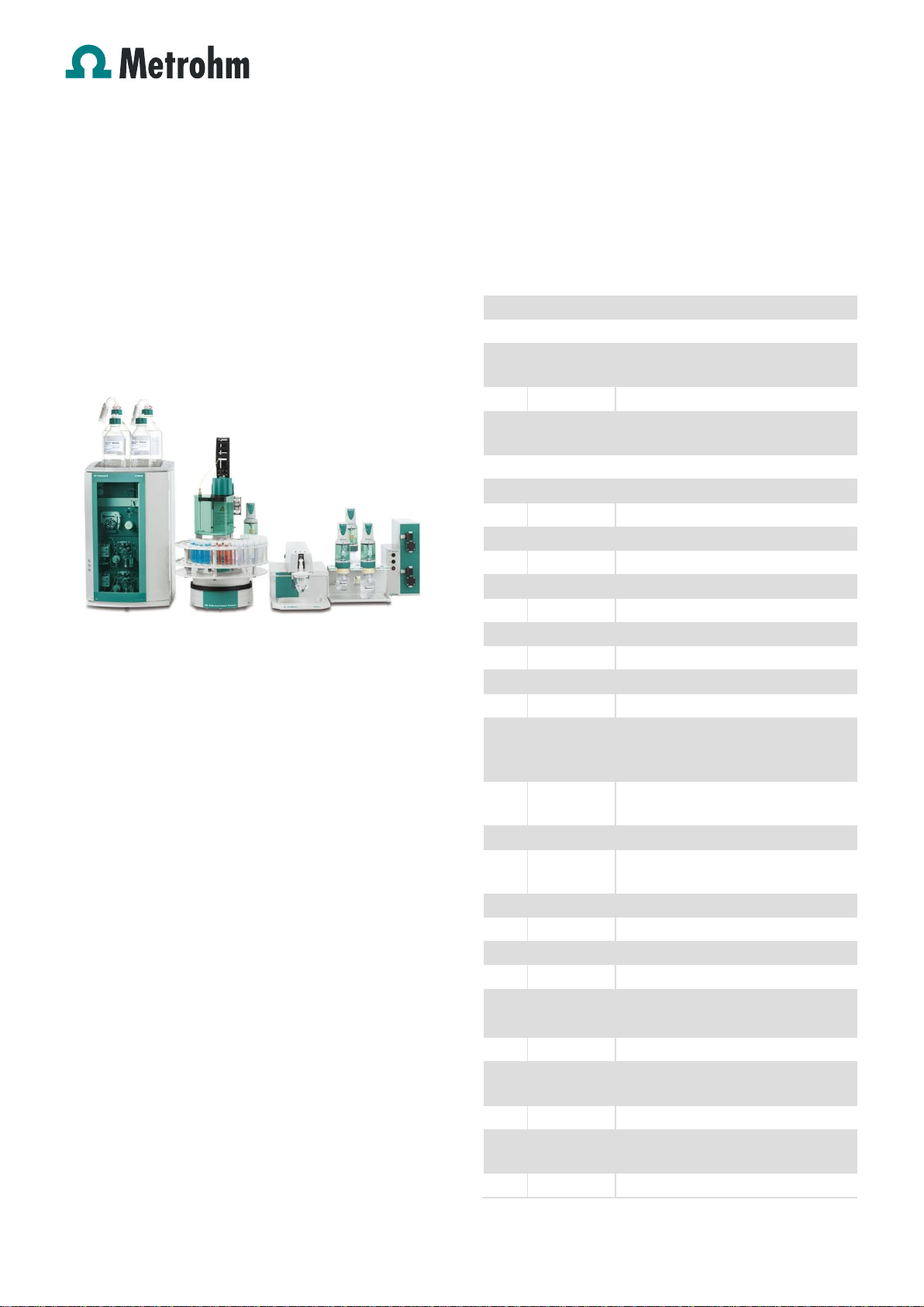
The «VoltIC pro I» combines a Professional AnCat IC
system with an automated VA system and shared sample
handling. «VoltIC pro I» is an all-in-one solution for the fully
automated analysis of anions, cations and heavy metals.
1. Scope of delivery
Fig.: VoltIC pro I system
Table of contents
1. Scope of delivery ...................................................... 1
2. Installation ................................................................ 2
2.1 Electrical connections ............................................... 2
2.2 850 Professional IC .................................................. 3
2.3 797 VA Computrace ................................................. 5
2.4 858 Professional Sample Processor ......................... 6
2.5 Connection of devices .............................................. 7
3 Software ................................................................... 8
3.1 Installation of an Serial port (RS) printer ................... 8
3.2 Installation of MagIC NetTM ..................................... 11
3.3 Configuration of MagIC NetTM ................................. 11
3.4 Installation of 797 VA Computrace software ........... 13
3.5 Configuration of 797 VA Computrace software ....... 13
3.6 Starting a determination ......................................... 14
4 Exemplary measurement ........................................ 15
5 Appendix ................................................................ 17
5.1 Time Program ......................................................... 17
Page 2

Application Bulletin 356
Installation instruction for «VoltIC pro I»
Page 2 of 18
1
6.2743.057
Sample tubes 11 mL 200x
1
6.2743.077
Stopper with perforation 200x
1
6.1808.280
Adapter Dosino Port 4 / M6
1
6.1805.530
FEP tube connection M6 200
1
6.1831.070
PEEK Cap. 1/16 In/0.75 mm 70 cm
1
6.1803.150
PTFE capillary 1/16 In/0.25 mm 1 m
1
6.1822.410
PEEK connection capillary
1
6.5620.000
Connecting set to Dosing Unit: port
4 1 6.1608.030
Bottle Colourless Glass 1 L / GL 45
1
6.2744.034
Coupling nozzle – UNF 10/32, 2
pieces
1
6.2744.070
Pressure screw short, 5 pieces
3
6.2744.080
Coupling Outer M6/UNF
1
6.1803.030
PTFE capillary 0.5 mm i.d. / 3m
Optional
1
6.6059.208
MagIC Net™ 2.x Progessional
Upgrade Multi - 3 licenses
1
6.1006.520
Metrosep A Supp 5 - 150/4.0
1
6.1006.500
Metrosep A Supp 4/5 Guard/4.0
1
6.1050.410
Metrosep C 4 - 100/4.0
1
6.1050.500
Metrosep C 4 Guard/4.0
2. Installation
We strongly recommend that the individual steps are carried
out in the order given below.
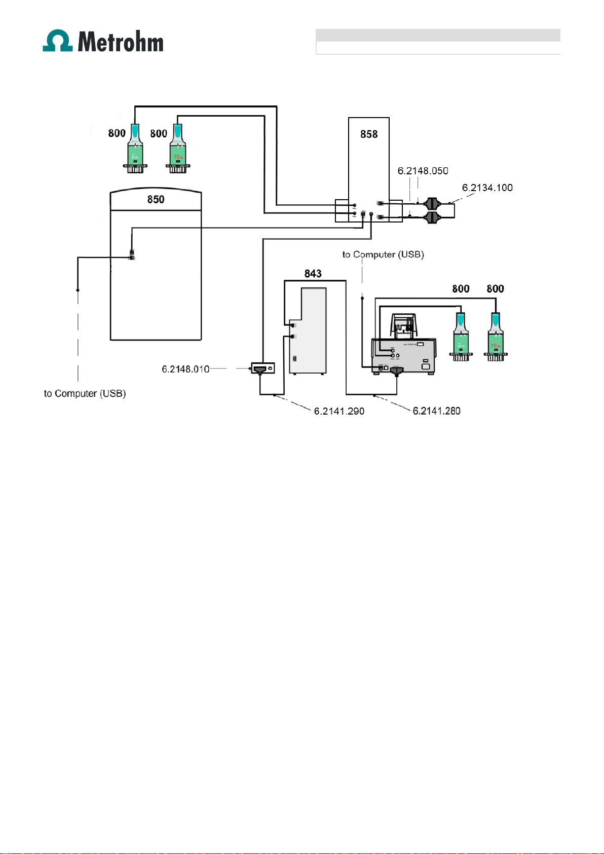
2.1 Electrical connections
In order to install the VoltIC pro I you have to establish
following connections mentioned below:
858 to 850: Connect «controller» output of 858 to USB
serial port of 850
800 Dosino (10 mL) to 858: Connect by MSB (Port 2)
800 Dosino (10 mL) to 858: Connect by MSB (Port 3)
2 x 800 Dosinos (2 mL) to 797 VA Computrace:
Connect by MSB (Port 1, Port 2)
797 VA Computrace to 843 Pump Station: Connect by
remote cable 6.2141.280
843 Pump Station to Remote box: Connect by remote
cable 6.2141.290
Remote box to 858: Connect to MSB 1
850 to computer: Connect 850 to USB serial port of PC
797 VA Computrace to computer: Connect USB serial
port of 797 VA Computrace to USB serial port of PC
Null modem cable: Attach the two USB RS converters
(6.2148.050) to the available USB ports of the 858 and
connect both using the RS232 cable (6.2134.100)
Page 3
Application Bulletin 356
Installation instruction for «VoltIC pro I»
Page 3 of 18
Fig.: Electrical connection diagram for the VoltIC pro I system
2.2 850 Professional IC
In order to install the Professional IC you have to perform
the following steps: Remove rollers and handle, place the
detector blocks in the instrument and connect the detector
cables, remove transport locking screws, connect the leak
sensor cable, connect the drainage tubing, and set up the
eluent bottles. Please refer to the 850 Professional IC
manual for a detailed description (chapters 2.6 and 2.8).
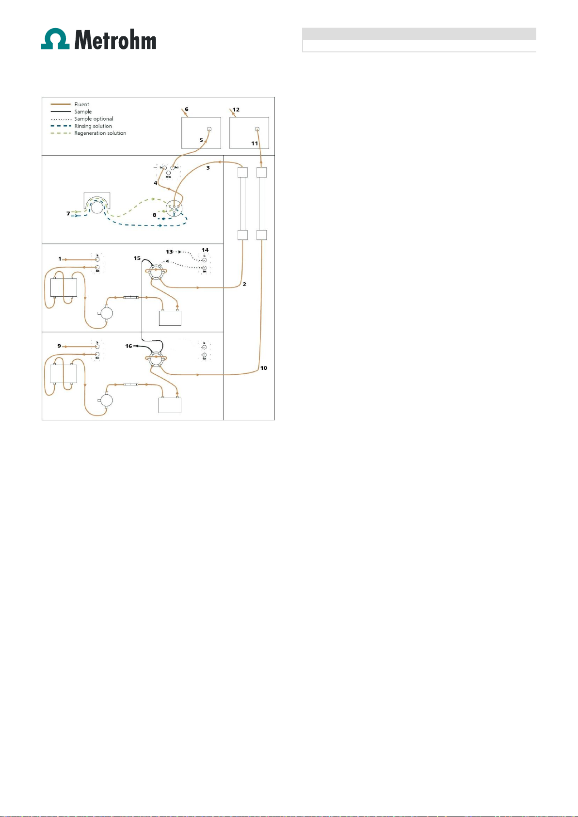
Capillaries are connected according to the following list and
the diagram below (also see manual chapters 2.14 to 2.18)
1. Connection to the eluent bottle for anion determination
2. Capillary to anion separation column
3. MSM inlet capillary – labeled with Eluent
4. MSM outlet capillary – labeled with Detector, which can
be connected to the MCS or directly to the detector.
The MCS air aspiration capillary is connected to the
CO2-absorber cartridge.
5. Capillary from MCS to anion detector, long PEEK
pressure screws (6.2744.090) are used for the MCS
connection
6. Detector outlet capillary to waste
7. Regeneration solution aspiration capillaries (PTFE, 0.97
mm ID), connected to two bottles with ultrapure water
and 50 mmol/L sulfuric acid respectively via peristaltic
pump tubing with orange/yellow stoppers (6.1826.320)
8. MSM regeneration solution outlet capillaries – labeled
with Waste – to waste
9. Connection to the Eluent bottle for cation determination
10. Capillary to cation separation column
11. Capillary from cation separation column to cation
detector
12. Detector outlet capillary to waste
13. Sample inlet capillary (PTFE, 90 cm, d=0.25 mm),
connected to the anion valve (position 1)
14. Optional sample degasser
Capillary connection (PTFE, 40 cm, d=0.5 mm) between
anion valve (position 2) and cation valve (position 1)
15. Connection capillary anion channel valve to cation
channel valve
16. Capillary to the waste
Page 4
Application Bulletin 356
Installation instruction for «VoltIC pro I»
Page 4 of 18
Prepare and degas two eluents suitable for the anion and
cation columns you want to use (see column manuals). For
Metrosep A Supp 5 a solution of 3.2 mmol/L Na2CO3 / 1.0
mmol/L NaHCO3 is adequate. For Metrosep C 4 a solution
of 1.7 mmol/L HNO3 / 0.7 mmol/L dipicolinic acid (DPA, 2,6Pyridinedicarboxylic acid) is adequate.
Provide regeneration solutions for the MSM Suppressor
(ultrapure water and 100 mmol/L sulfuric acid).
Page 5
Application Bulletin 356
Installation instruction for «VoltIC pro I»
Page 5 of 18
2.3 797 VA Computrace
Following steps have to be done to install the MVA-3
system:
a) Establish the following tubing connections between the system components
b) Establish the tubing connections for 800 Dosinos for the addition of solutions:
Page 6
Application Bulletin 356
Installation instruction for «VoltIC pro I»
Page 6 of 18
c) Establish the tubing connections at the measuring
head of the 797 VA Computrace:
2.4 858 Professional Sample Processor
For a detailed description, please refer to the 858
Professional Sample Processor manual. In general, you will
have to do the following: Plug in the Swing Head connection
cable, and plug in the power supply cable. The sample
processor initializes and lifts its Swing Head, once it is
connected to the IC device and the MSB connection is
recognized. Afterwards, it is possible to mount the retaining
plate (manual chapters 3.2 - 3.4).
Mount the Dosino holder (6.2057.040) on the side of the
tower and attach a 10 mL Dosing Unit (6.3032.210) and a
800 Dosino (2.800.0010) to it.
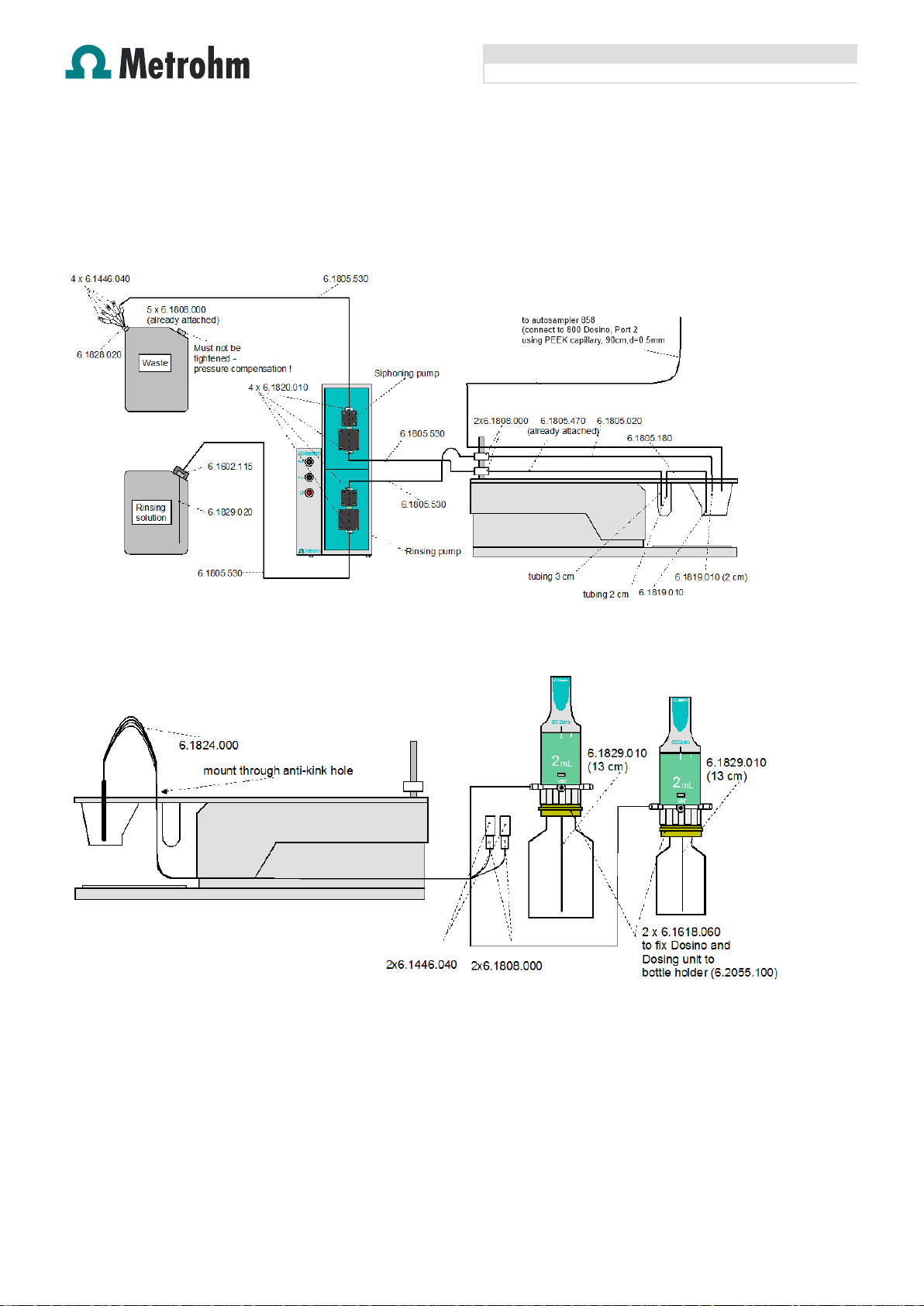
A rinsing station is mandatory for this setup.
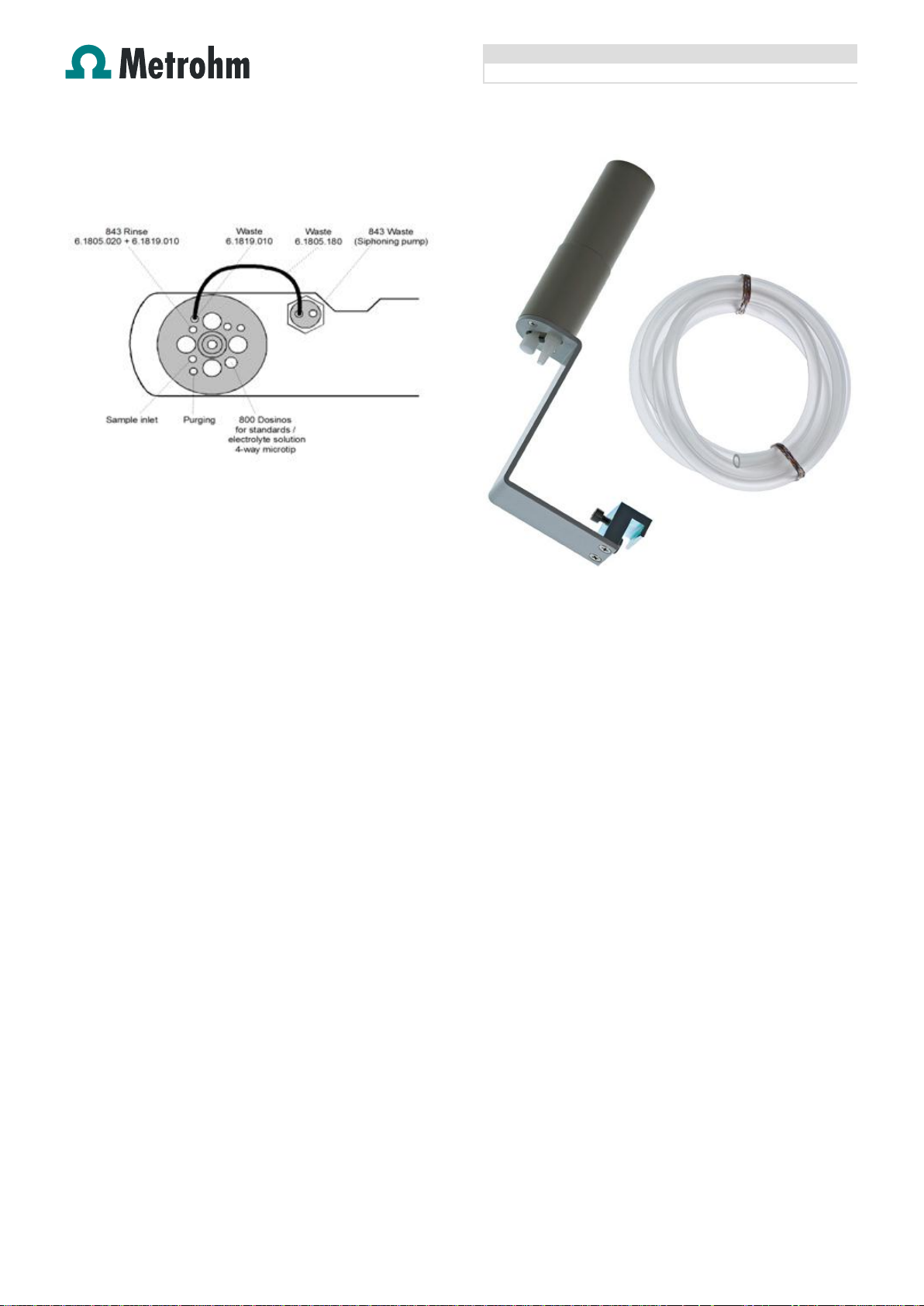
The rinsing station is mounted onto the sample processor,
which is easiest when the rack is temporarily removed. The
exact position can be adjusted by directing the needle into
the rinsing station with the manual control (in the window
manual). The inner compartment approximately relates to a
swing head angle of ~116°, the outer one approximately
relates to ~110°. Memorize your angle settings.
Fig.: Rinsing station parts
A tubing is fixed at the bottom of the rinsing station to drain
the waste water. A bottle of ultrapure water is needed as
reservoir for the rinsing solution. The rinsing solution is
transported by one channel of the peristaltic pump of the
sample processor.
Mount the rinsing station on the sample processor.
Connect ultrapure water reservoir with the peristaltic pump
(via pump tubing (6.1826.360) and PEEK screws / tubing
olives) using a PTFE capillary (part of 6.1803.030). Then
connect the peristaltic pump (via pump tubing and PEEK
Screws / tubing olives) to the inner compartment of the
rinsing station also using a PTFE capillary (part of
6.1803.030).
The outer compartment of the rinsing station is connected to
the waste container.
Page 7

Application Bulletin 356
Installation instruction for «VoltIC pro I»
Page 7 of 18
2.5 Connection of devices
The 858 Professional Sample Processor, the 850
Professional IC AnCat system and the 797 VA Computrace
are connected with each other via the 800 Dosino with a 10
mL Dosing Unit mounted on the 858 Professional Sample
Processor.
Connect the sample needle to Port 3 of the 10 mL Dosing
Unit at the 800 Dosino using a PEEK capillary (70 cm,
d=0.75 mm, 6.1831.070). The 850 Professional IC AnCat
system is connected to the Dosing Unit at Port 1 using a
PTFE capillary (90 cm, d=0.25 mm, part of 6.1803.150). The
sample inlet capillary (PEEK, 90 cm, d=0.5 mm, part of
6.1822.410) of the 797 VA Computrace is connected to the
Dosing Unit at Port 2. Port 4 of the Dosing Unit is equipped
with an adapter (6.1808.280) and a FEP tube (6.1805.530)
and connected to the waste.
The second 10 mL Dosing Unit with an 800 Dosino is
connected to one capillary of the fourfold micro tip and is
used to dilute the sample for the VA measurement
automatically (solution j).
Fig.: Capillary connections to and from rinsing station
Page 8

Application Bulletin 356
Installation instruction for «VoltIC pro I»
Page 8 of 18
Fig.: schematic configuration of the VoltIC pro I system
a) PEEK, 70 cm, d=0.75 mm, 6.1831.070 / b) PTFE, 90 cm, d=0.25 mm, part of 6.1803.150 / c) PEEK, 90 cm, d=0.50 mm, part of 6.1822.410 /
d) FEP tube, 6.1805.530 / e) Fourfold micro tip, 6.1824.000 / f) FEP tube, 6.1805.530 / g) PTFE, 40 cm, d=0.50 mm, part of 6.1803.030 / h)
Heavy metal multistandard solution / i) buffer solution pH 4.6 / j) ultrapure water / k) rinsing solution for VA / l) anion eluent / m) cation eluent / n)
rinsing solution for rinsing station
3 Software
3.1 Installation of an Serial port (RS) printer
The data generated in the VA Computrace software is being
transferred to MagIC Net™ via a generic text printer. The
following steps describes how a generic text printer is being
installed under Windows 7.
Check the newly created COM-ports in your system after
connecting the null modem cable and USB RS adapters
(refer 2.1): Start Control Panel Device Manager
Under Ports (COM&LPT) the newly created USB serial ports
are visible (e.g. COM14 and COM15):
Page 9

Application Bulletin 356
Installation instruction for «VoltIC pro I»
Page 9 of 18
Check and – if necessary – adjust the «Port Settings» to the
following parameters of both COM ports under «Properties»
by double-clicking on each COM port:
Create a generic text printer under: «Start» «Devices and
Printers» «Add a Printer»
Add a local printer by using the first newly created COM port
(e.g. COM 14) and select the «Generic / Text only» printer
driver. Use the current version of the driver. Rename the
printer to «RS Printer».
Page 10

Application Bulletin 356
Installation instruction for «VoltIC pro I»
Page 10 of 18
Do not share this printer, do not print a test page and finish
the printer wizard.
Configure the newly created «RS Printer» go to «Start»
«Devices and Printers», right-click on the «RS printer» and
select «Printer properties»
Check the selected COM-port and the settings under
«Ports» and «Configure Port…»
Check the settings under «Advanced»:
Page 11

Application Bulletin 356
Installation instruction for «VoltIC pro I»
Page 11 of 18
Enter «stopp» in the field «End Print Job» under «Printer
Commands»
3.2 Installation of MagIC NetTM
All programs must be shut down first. Install MagIC NetTM
(MagIC NetTM CD). All the standard directories proposed by
the program should be accepted. Restart windows.
Connected USB devices are automatically recognized when
MagIC Net™ is started. The Microsoft Installation Wizard is
accepted and executed. After confirmation of the
automatically generated request, the devices are stored in
the configuration. The devices are predefined as «850
Professional IC 1» and «858 Professional Sample
Processor 1». Name them accordingly, if other names
appear in your configuration (e.g. due to changed setting on
your computer).
3.3 Configuration of MagIC NetTM
In the window configuration, the 850 Professional IC, the
858 Professional Sample Processor and the columns
Metrosep A Supp 5 - 150/4.0 and Metrosep C 4 - 100/4.0
are visible. Add and define the eluents and the suppressor
solutions.
The settings for the rack require a «work position» fitting to
the respective rack (e.g. 125 mm for rack 6.2041.450).
Click «Apply» and «OK».
Also define an «External 1» position to access the rinsing
station for rinsing the needle. The needle position is in the
inner compartment which corresponds to an angle of ~116°
and a work position of 120 mm. The exact angle depends
on your installation (see chapter 2.4).
For the outer compartment, an external position 2 can be
defined with an angle of ~110° and a work position of 60
mm. The external position 2 could be used as drain position
(e.g. to expel sample directly to the waste), however, it is
not carried out during the time program of method VoltIC pro
I.
Page 12

Application Bulletin 356
Installation instruction for «VoltIC pro I»
Page 12 of 18
For the data transfer from the VA Computrace software to
MagIC Net™ an RS 232 device must be added to the device
list as follows:
Go to the Configuration window in MagIC Net™ and select
«New» from the «Edit» button in the Device window. Select
the «RS 232 Device» from the «Miscellaneous» list:
Rename the device «797 RS232 Printer». Enter «1» in the
field «serial number».
Make the following settings under «RS 232»:
(Attention: the second newly generated COM port by the
null modem cable has to be selected as «COM Port», e.g.
COM 15 !)
Enter «stopp» in the field «Terminator for receive».
In the window method, import the method for VoltIC pro I
from the installation CD: Go to File → method manager and
choose your method group. Afterwards, click on edit →
import and choose the pathway on the installation CD
(MagICnet\examples\methods\VoltICpro.imet).
The method carries out a parallel determination of cations
and anions. Immediately after starting the anion
determination, the cation determination (of the same
sample) is initialized. Samples could be taken from the
same vial, or from two vials with one of them containing the
acidified sample solution for cation determination. Both
measurements are recorded in the same data file. In order
to measure samples from two different vial please select
method «VoltICpro_mod.imet» from the same folder.
In the window method, open the VoltICpro method and
assign the following equipment: Assign the column
Page 13

Application Bulletin 356
Installation instruction for «VoltIC pro I»
Page 13 of 18
Metrosep A Supp 5 - 150/4.0 to the analysis anion, assign
the column Metrosep C 4 - 100/4.0 to the analysis cation,
assign the two eluents to their respective IC pump, match
the two suppressor solutions to the IC peristaltic pump, and
define the rack of the connected sample processor. Adjust
the temperature of the column oven to 30°C. Save the
method.
In order to start the equilibration, go to the window work
place, load your method, and press «Start HW». Before
inserting the columns, flush the system for about 10 minutes
and get rid of air bubbles (by using the purge valve and
syringe), then insert and rinse the precolumns for 10
minutes, and only afterwards put the analytical columns into
the flow (see also 850 manual).
3.4 Installation of 797 VA Computrace software
Install the software. All the standard directories proposed by
the program should be accepted. Restart windows.
Connected USB devices are automatically recognized when
VA Computrace software is started.
3.5 Configuration of 797 VA Computrace software
Make the following general settings in the main window
under «Settings» «General Settings»s” and click «OK»:
Load method «Det of Zn Cd Pb Cu_IC_VA.mth», modify or
create a new method.
Click on «Dosinos» in the «Working Method Specifications»
window and make following settings:
Page 14

Application Bulletin 356
Installation instruction for «VoltIC pro I»
Page 14 of 18
3.6 Starting a determination
The hyphenated analysis of IC and VA follows the cycle
described below:
All sample information (sample ID, dilution factor, etc…) is
programmed in MagIC NetTM.
MagIC NetTM triggers VA Computrace software by remote
signal.
VA Computrace software will feeds back information to
MagIC NetTM after preparing the measuring cell (before
sample transfer) and after VA analysis has been finished
and the cell has been prepared for the next analysis.
Please follow the steps below for system startup:
Close all applications
Turn on all instruments (843 Pump Station should be
switched on after the 797 VA Computrace, otherwise
pumps start pumping)
Start MagIC NetTM and check if all hardware
components have been recognized and available in the
configuration window.
Load method «VoltICpro.imet» in MagIC NetTM
Start VA Computrace and check if hardware
components have been recognized
Load «Det of Zn Cd Pb Cu_IC_VA.mth» in VA
Computrace software
Under «Settings» «General Settings»
«Automation» activate «Remote Start» and «End of
Sample» and click «OK» (This must be done with
every restart of VA Computrace software as these
settings are not saved!)
Prepare both systems:
Ion chromatograph
o Equilibrate the system («Start HW»)
o Check for stable system pressure (+/- 0.1
MPa) on both channels; remove air bubbles
manually if necessary
o Check for stable baselines (anion channel:
~0.9 µS/cm, cation channel: ~680 µS/cm for
the mentioned eluents, refer 2.2)
VA
o Check working electrode and reference
electrode; refill if necessary
o Check nitrogen pressure, performance of
working electrode (create new drops)
o Perform electrode check
Start the VA method (VA will wait for trigger signal from
MagIC NetTM)
Enter the amount of standards and standard
concentrations in MagIC NetTM
Enter sample table in MagIC NetTM
For quantitative analysis, samples subjected to cation
analysis are normally acidified, whereas anion analysis is
normally carried out with unmodified samples. Method
«VoltICpro.imet» includes only one sample for anion, cation
and heavy metal analysis. Method «VoltICpro_mod.imet»
includes 2 sample vials on the rack for each sample (an
unmodified one for anion determination and an acidified one
for cation and heavy metal determination). According to the
method «VoltICpro_mod.imet» the position of the vial for
anion determination should be defined in the column
«sample position» and the position of the vial for cation and
heavy metal determination is the subsequent one.
Both methods «VoltICpro.imet» and «VoltICpro_mod.imet»
include variable sample volume for VA analysis (0.2 mL –
10 mL). The desired sample volume is entered as «Value 1»
(see sample table below).
As the VA Computrace software calculates with a fixed
sample volume of 10 mL, the difference to 10 mL is dosed
by the optional Dosino (ultrapure water) directly into the VA
vessel.
Page 15

Application Bulletin 356
Installation instruction for «VoltIC pro I»
Page 15 of 18
Correlation
coefficient
Relative standard
deviation [%]
Lithium
0.999984
0.761
Sodium
0.999947
1.347
Ammonium
0.999939
1.371
Potassium
0.999776
2.904
Calcium
0.999864
1.813
Magnesium
0.999973
0.890
Correlation
coefficient
Relative standard
deviation [%]
Fluoride
0.999954
1.594
Chloride
0.999988
0.786
Nitrite
0.999992
0.650
Bromide
0.999993
0.584
Nitrate
0.999993
0.587
Phosphate
0.999997
0.408
Sulfate
0.999992
0.616
The recalculation to the actual sample volume used (Value
1) takes place after the VA analysis in MagIC NetTM.
Therefore, your sample table might look like the following
one:
Fig.: Sample table excerpt showing the use of «VoltICpro.imet»
For evaluation and after recording the first chromatogram,
check the retention times of your compounds. Since they
depend on the performance of your column, you may have
to adjust them in your method.
4 Exemplary measurement
An exemplary measurement was performed, including the
ions fluoride, chloride, nitrite, bromide, nitrate, phosphate,
sulfate, lithium, sodium, ammonium, potassium, calcium,
and magnesium (1000 µg/L each), zinc, cadmium, lead and
copper. Anions and cations were measured from separate
sample vials with the sample for cation measurement being
acidified with 50 µL nitric acid (2 mol/L) per 50 mL sample.
The two following chromatograms were recorded in parallel.
For the calibration, the average peak areas of 3 injections
were evaluated. Within the concentration range of 20 – 1000
µg/L, a quadratic curve type was used for evaluation of
anions, and a linear curve type was used for evaluation of
cations. Correlation coefficients and standard deviations are
listed in the following table. The calibration curves for
chloride and sodium are shown as examples.
Fig.: Statistical data of a six-point cation calibration from 20 µg/L to
1000 µg/L
Fig.: Standard chromatogram cations, 1000 µg/L
Fig.: Standard chromatogram anions, 1000 µg/L
Fig.: Statistical data of a six-point anion calibration from 20 µg/L to
1000 µg/L
Fig.: Chloride calibration curve from 20 µg/L to 1000 µg/L
Page 16

Application Bulletin 356
Installation instruction for «VoltIC pro I»
Page 16 of 18
Fig.: Sodium calibration curve from 20 µg/L to 1000 µg/L
Fig.: Example of a combined report for IC and VA results in the
MagIC Net™ database
Fig.: Example voltammogramm of Zn, Cd, Pb and Cu determination
Fig.: Standard addition graphs of Zn, Cd, Pb and Cu determination
(sample: table water, Add 1)
Page 17

Application Bulletin 356
Installation instruction for «VoltIC pro I»
Page 17 of 18
5 Appendix
5.1 Time Program
Time program «VoltICpro.imet»
Page 18

Application Bulletin 356
Installation instruction for «VoltIC pro I»
Page 18 of 18
 Loading...