

Page 1
IC Equipment set
Variocell for Bioscan – 6.5331.1X0
Manual
8.110.8009EN
Page 2

Page 3

Metrohm AG
CH-9101 Herisau
Switzerland
Phone +41 71 353 85 85
Fax +41 71 353 89 01
info@metrohm.com
www.metrohm.com
IC Equipment set
Variocell for Bioscan – 6.5331.1X0
Manual
8.110.8009EN 10.2009 zst
Page 4

Teachware
Metrohm AG
CH-9101 Herisau
teachware@metrohm.com
This documentation is protected by copyright. All rights reserved.
Although all the information given in this documentation has been
checked with great care, errors cannot be entirely excluded. Should you
notice any mistakes please send us your comments using the address
given above.
Page 5

■■■■■■■■■■■■■■■■■■■■■■
Table of contents
1 Introduction 1
1.1 Description ............................................................................ 1
1.2 About the documentation ................................................... 1
1.2.1 Symbols and conventions ........................................................ 1
2 Components and connectors 3
3 Installation 5
3.1 Installing the Variocell ......................................................... 5
3.2 Exchanging the auxiliary electrode ..................................... 6
4 Maintenance - Taking out of operation 9
4.1 Maintaining the Variocell ..................................................... 9
Table of contents
4.2 Taking the cell out of operation ....................................... 11
5 Technical specifications 12
5.1 General ................................................................................ 12
5.2 Gold Variocell ...................................................................... 12
5.3 Glassy-Carbon Variocell ..................................................... 13
5.4 Platinum Variocell .............................................................. 13
5.5 Silver Variocell .................................................................... 14
6 Accessories 15
6.1 Scope of delivery ................................................................ 15
6.1.1 Equipment with Au Variocell for Bioscan ................................ 15
6.1.2 Equipment with GC Variocell for Bioscan ............................... 16
6.1.3 Equipment with Pt Variocell for Bioscan ................................. 18
6.1.4 Equipment with Ag Variocell for Bioscan ................................ 19
Index 21
IC Equipment set Variocell for Bioscan
■■■■■■■■
III
Page 6

Table of figures
Table of figures
Figure 1 Components and connectors of the Variocell .................................... 3
Figure 2 Remove the working electrode .......................................................... 7
■■■■■■■■■■■■■■■■■■■■■■
■■■■■■■■
IV
IC Equipment set Variocell for Bioscan
Page 7
■■■■■■■■■■■■■■■■■■■■■■
1 Introduction
1.1 Description
The Variocell is an electrochemical flow cell with an exchangeable working electrode for usage in Bioscan instruments.
The Variocell is constructed in such a way that both of the eluent outlets
can serve as either inlets or outlets.
The Variocell is available in four versions:
■ Gold Variocell 6.1254.110
■ Glassy-Carbon Variocell 6.1254.120
■ Platinum Variocell 6.1254.130
■ Silver Variocell 6.1254.140
A more detailed description of the specifications and areas of application
for the individual cells can be found in the chapter Technical specifica-
tions, page 12.
1 Introduction
1.2 About the documentation
Caution
Please read through this documentation carefully before putting the
instrument into operation. The documentation contains information
and warnings which the user must follow in order to ensure safe operation of the instrument.
1.2.1 Symbols and conventions
The following symbols and styles are used in this documentation:
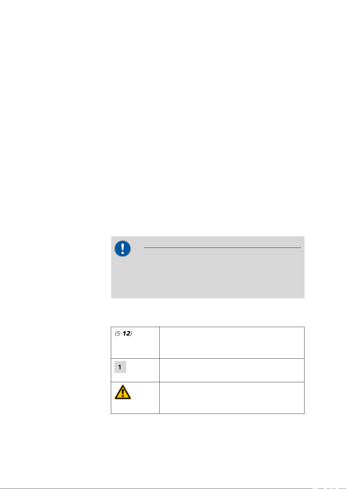
Cross-reference to figure legend
The first number refers to the figure number, the
second to the instrument part in the figure.
Instruction step
Carry out these steps in the sequence shown.
Warning
IC Equipment set Variocell for Bioscan
This symbol draws attention to a possible life hazard
or risk of injury.
■■■■■■■■
1
Page 8
1.2 About the documentation
■■■■■■■■■■■■■■■■■■■■■■
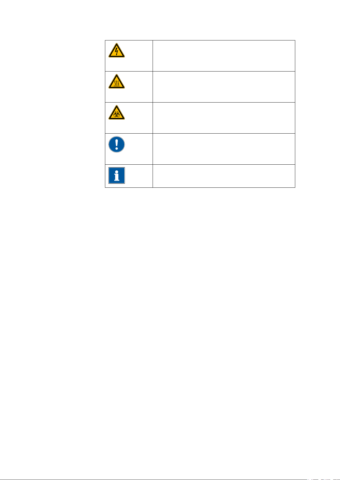
Warning
This symbol draws attention to a possible hazard due
to electrical current.
Warning
This symbol draws attention to a possible hazard due
to heat or hot instrument parts.
Warning
This symbol draws attention to a possible biological
hazard.
Caution
This symbol draws attention to a possible damage of
instruments or instrument parts.
Note
This symbol marks additional information and tips.
■■■■■■■■
2
IC Equipment set Variocell for Bioscan
Page 9
■■■■■■■■■■■■■■■■■■■■■■
1
2
3
4
5
6
7
8
9
10
11
12
2 Components and connectors
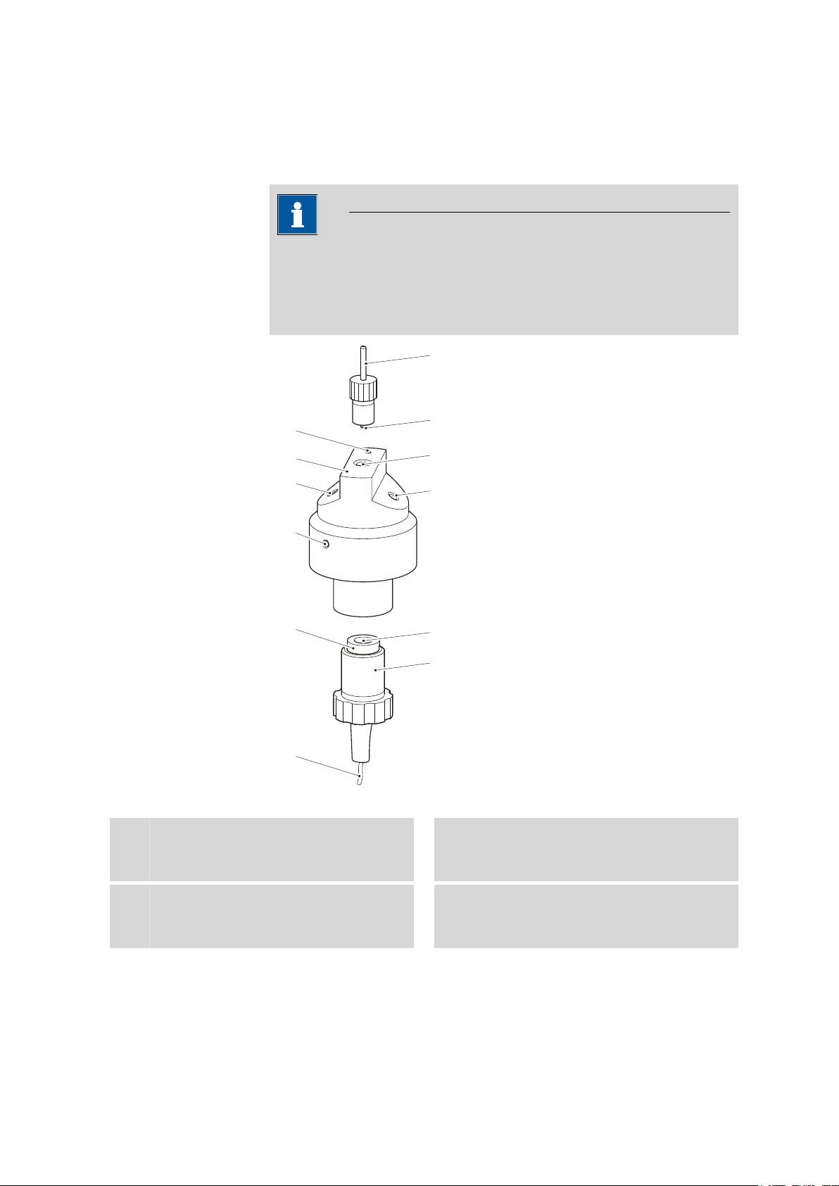
Note
The Variocell is supplied fully mounted. Immediately after receipt, check
whether the shipment has arrived complete and without damage by
comparing the delivery note with the list of accessories (see Chapter
6.1, page 15).
2 Components and connectors
Figure 1 Components and connectors of the Variocell
1
3
IC Equipment set Variocell for Bioscan
Reference electrode connector
For connecting the black 6.2156.000 electrode cable.
Auxiliary electrode
Reference electrode
2
Auxiliary electrode connector
4
For connecting the blue 6.2156.000 electrode cable.
■■■■■■■■
3
Page 10

■■■■■■■■■■■■■■■■■■■■■■
Reference electrode reservoir
5
Eluent outlet
7
For connecting the 6.1803.030 PTFE capillary using one of the 6.2744.014 pressure
screws provided.
Can also be used as eluent inlet. The PTFE
capillary must however always be connected to the eluent outlet.
Working electrode (exchangeable)
9
Exchangeable electrode platelet.
Fastening ring
11
For fastening the working electrode holder.
Eluent inlet
6
For connecting the connection capillary
using one of the 6.2744.014 pressure
screws provided.
Can also be used as eluent outlet.
Clamping screw
8
For adjusting the auxiliary electrode holder
when inserting the working electrode.
Auxiliary electrode holder
10
Holder for working electrode.
Working electrode connector
12
For connecting the red 6.2156.000 electrode cable.
■■■■■■■■
4
IC Equipment set Variocell for Bioscan
Page 11

■■■■■■■■■■■■■■■■■■■■■■
3 Installation
3.1 Installing the Variocell
Caution
Never switch the Variocell on, when...
■ … it is not completely connected, or
■ … if it is not simultaneously being rinsed by a conductive eluent.
The working electrode or other electronic components may be damaged.
Installing the Variocell
3 Installation
1
Removing the reference electrode
Unscrew the reference electrode.
Removing the reference electrode prior to the filling of the cell prevents air bubble formation while the reservoir is being filled.
2
Connecting the eluent inlet
Use a pressure screw 6.2744.014 to attach the column connection
capillary (attached to the separation column) to the eluent inlet (1-6)
of the Variocell.
In order to avoid dead volume while doing so, slide the capillary up
to the stop in the cell and then rotate the pressure screw in until the
capillary is fixed in place. Do not however tighten the pressure screw
too much, as this could cause damage to the thread.
3
Connecting the eluent outlet
■ Use a pressure screw 6.2744.014 to attach one end of the sup-
plied PTFE capillary 6.1803.030 to the eluent outlet (1-7) of the
Variocell.
In order to avoid dead volume while doing so, slide the capillary
up to the stop in the cell and then rotate the pressure screw in
until the capillary is fixed in place. Do not however tighten the
pressure screw too much, as this could cause damage to the
thread.
IC Equipment set Variocell for Bioscan
■■■■■■■■
5
Page 12

3.2 Exchanging the auxiliary electrode
4
5
■■■■■■■■■■■■■■■■■■■■■■
■ Guide the free end of the drainage capillary into a sufficiently
large waste container and fasten it there.
Inserting the reference electrode
■ Switch on the high pressure pump of the chromatography system.
This will cause the reservoir of the reference electrode (1-5) to fill
up.
Note
The reservoir will overflow when the reference electrode is inserted. Keep paper towels close to hand.
■ Insert the reference electrode into the filled reservoir and screw it
on. Take care to allow air bubbles to escape from the reservoir.
Installing the Variocell
Place the Variocell into the measuring cell holder of the Bioscan.
Rotate the cell in its holder in such a way that the eluent outlet is
located as high up as possible. This will allow any air bubbles which
may appear to escape from the cell.
6
Connecting the electrode cable
■ Connect the electrode cable 6.2156.000 to the Variocell using the
three connector plugs (red - working electrode,
blue - auxiliary electrode, black - reference electrode).
■ Connect the other end to the connector of the 871 Advanced
Bioscan.
3.2 Exchanging the auxiliary electrode
The Variocell is constructed in such a way that it can be utilized for a multitude of different applications. It need only be ensured that the correct
working electrode is being utilized for the desired application.
Working electrodes have a front side and a rear side. The front side is polished smooth and glossy, while the rear side is more matte. "Au", "Ag" or
"Pt" is also engraved on the rear side of working electrode plates made of
gold, silver or platinum, respectively.
■■■■■■■■
6
The working electrode must always be inserted with the smoothly polished, glossy side facing outward.
Proceed as follows to exchange the working electrode:
IC Equipment set Variocell for Bioscan
Page 13

■■■■■■■■■■■■■■■■■■■■■■
1
2
Dismantling the Variocell
1
Dismantling the Variocell
■ In the software, switch off the Variocell and the high pressure
pump.
■ Dismantle all three electrode cables.
■ Remove the Variocell from the holder in the instrument.
■ Unscrew the eluent inlet and eluent outlet.
2
Removing the auxiliary electrode holder
■ Unscrew the fastening ring (1-11) on the working electrode
holder and remove it.
■ Carefully pull the working electrode holder (1-10) out of the
Variocell.
Exchanging the working electrode
3 Installation
Mounting ring
1
1
Removing the old working electrode
Figure 2 Remove the working electrode
Silicone holder
2
Pull back the mounting ring (2-1) and use the tips of your fingers to
remove the electrode from the silicone holder (2-2).
Note
IC Equipment set Variocell for Bioscan
Do not use any tools to remove the working electrode.
Using tools could cause the edges of the working electrode to
become damaged, which might have an influence on the measuring results.
■■■■■■■■
7
Page 14

3.2 Exchanging the auxiliary electrode
2
Reinstalling the Variocell
1
2
■■■■■■■■■■■■■■■■■■■■■■
Inserting new working electrode
■ Insert new working electrode (1-9) into the silicone holder (2-2)
of the working electrode holder (1-10) with the polished side facing outward.
■ Remove fingerprints with acetone or methanol.
■ Secure the working electrode with the mounting ring (2-1).
Mounting the working electrode holder
■ Guide the working electrode holder into the Variocell aligning it
with the clamping screw (1-8).
■ Pull the fastening ring (1-11) over the electrode cable and screw
on just tightly enough to ensure that the working electrode
holder is held firmly in place.
Installing the Variocell
Reinstall the Variocell in accordance with the instructions Installing
the Variocell, page 5.
■■■■■■■■
8
IC Equipment set Variocell for Bioscan
Page 15

■■■■■■■■■■■■■■■■■■■■■■
4 Maintenance - Taking out of operation
4 Maintenance - Taking out of operation
In principle, the Variocell is maintenance-free.
Contamination appearing after prolonged utilization could however influence the measuring result. If the measuring signal should exhibit excessive
noise, then you can quite easily remove the Variocell and clean it. To do
so, proceed in accordance with the following instructions:
4.1 Maintaining the Variocell
Caution
The Variocell may not be unscrewed as long as the working electrode is
still mounted.
The spacer could become damaged.
Proceed as follows to dismantle the Variocell:
Dismantling the Variocell
In the software, switch off the Variocell and the high pressure pump.
1
Dismantle all three electrode cables.
2
Remove the Variocell from its holder in the instrument.
3
Unscrew the eluent inlet and eluent outlet.
4
■ Unscrew the fastening ring (1-11) on the working electrode
5
holder and remove it.
■ Carefully pull the working electrode holder (1-10) out of the
Variocell.
Only now, unscrew the two pieces of the variocell.
6
IC Equipment set Variocell for Bioscan
■■■■■■■■
9
Page 16

4.1 Maintaining the Variocell
■■■■■■■■■■■■■■■■■■■■■■
Cleaning the components of the Variocell
1
Cleaning the spacer
■ Remove the spacer.
■ Rinse with ultra pure water and dry.
2
Clean the auxiliary electrode
■ Carefully clean the auxiliary electrode (1-3) with a soft cloth
soaked with acetone or methanol.
Avoid any use of force while doing so; the electrode could
become damaged.
■ Rinse off the interior side of the cell with ultra pure water and dry
thoroughly.
3
Cleaning the working electrode
See also (see Figure 2, page 7).
■ Remove the working electrode (1-9) from the working electrode
holder (1-10).
To do so, pull back the mounting ring (2-1) and use the tips of
your fingers to remove the electrode from the silicone holder
(2-2).
Do not use any tools to remove the working electrode. Using
tools could cause the edges of the working electrode to become
damaged, which might have an influence on the measuring
results.
■ For the cleaning sequence, please follow the instructions con-
tained in the chapter entitled Cleaning the working electrode in
the 871 Advanced Bioscan manual.
Mounting the Variocell
1
Assembling the Variocell
Caution
Make sure that ...
■■■■■■■■
10
■ … the spacer is undamaged and
■ … the surfaces of the spacer are dry and free of dust.
Remove fingerprints with acetone or methanol.
IC Equipment set Variocell for Bioscan
Page 17

■■■■■■■■■■■■■■■■■■■■■■
4 Maintenance - Taking out of operation
■ Insert spacer.
■ Screw together the two pieces of the Variocell.
2
Inserting the working electrode
Note
Working electrodes have a front side and a rear side. The front
side is polished smooth and glossy, while the rear side is more
matte. "Au", "Ag" or "Pt" is also engraved on the rear side of
working electrode plates made of gold, silver or platinum, respectively.
The working electrode must always be inserted with the smoothly
polished, glossy side facing outward.
■ Insert the working electrode (1-9) into the silicone holder (2-2) of
the working electrode holder (1-10) with the polished side facing
outward.
■ Remove fingerprints with acetone or methanol.
■ Secure the working electrode with the mounting ring (2-1).
■ Guide the working electrode holder into the Variocell aligning it
with the clamping screw (1-8).
■ Pull the fastening ring over the electrode cable and screw on just
tightly enough to ensure that the working electrode holder is held
firmly in place.
3
Installing the Variocell
Install the cleaned Variocell back in the 871 Advanced Bioscan. To do
so, follow the instructions in chapter Installing the Variocell, page 5.
4.2 Taking the cell out of operation
Caution
The Variocell should be cleaned and stored in its original packaging
when not in use.
IC Equipment set Variocell for Bioscan
■■■■■■■■
11
Page 18

5.1 General
5 Technical specifications
5.1 General
■■■■■■■■■■■■■■■■■■■■■■
Structure
Cell volume
Working tempera-
Flow cell with working, reference and auxiliary electrode.
0.7 µL with the supplied 50 µm spacer.
The cell should not be operated continuously over 45 °C.
ture
Reference electrode
Type
Conversion to
Solid phase reference electrode
E
Hy-REF
/mV = E
Ag/AgCl
5.2 Gold Variocell
Working electrode
Material
Applications
Gold
Sugar and amino acids
■ Mono-, di-, oligo- and polysaccharides
■ Sugar alcohols
■ Sugar amines
■ Sugar acids
■ Amino acids
■ Antibiotics
/mV – 328 + 29.9 pH (mV)
Ag/AgCl
Working area
Acid medium
Alkaline
medium
■■■■■■■■
12
-0.35 V…+1.1 V
-1.25 V…+0.75 V
IC Equipment set Variocell for Bioscan
Page 19

■■■■■■■■■■■■■■■■■■■■■■
5.3 Glassy-Carbon Variocell
Working electrode
Material
Glassy-Carbon
5 Technical specifications
Applications
Aromatics and amines
■ Catecholamines, aromatic amines
■ Inorganic ions (nitrite, sulfite, ...)
■ Phenols
■ Vitamins
■ Some amino acids
Working area
Acid medium
Alkaline
-0.8 V… +1.3 V
-1.5 V… +0.6 V
medium
5.4 Platinum Variocell
Working electrode
Material
Applications
Platinum
Special applications
■ Alcohols
■ Glycols
■ Hydrogen peroxide
■ Hydrazine
■ Arsenite, hypochlorite
Working area
Acid medium
Alkaline
-0.2 V… +1.3 V
-0.9 V… +0.65 V
medium
IC Equipment set Variocell for Bioscan
■■■■■■■■
13
Page 20

5.5 Silver Variocell
5.5 Silver Variocell
Working electrode
Material
Silver
■■■■■■■■■■■■■■■■■■■■■■
Applications
Working area
Acid medium
Alkaline
medium
Applications relevant to the environment
■ Halogenides
■ Cyanide, sulfide
■ Thiosulphate
■ Pharmaceutics
-0.55 V… +0.4 V
-1.2 V… +0.1 V
■■■■■■■■
14
IC Equipment set Variocell for Bioscan
Page 21

■■■■■■■■■■■■■■■■■■■■■■
6 Accessories
6.1 Scope of delivery
6.1.1 Equipment with Au Variocell for Bioscan
6.5331.110 IC Equipment set Variocell for Bioscan
Qty. Order no. Description
1 6.1254.110 Gold Variocell for Bioscan
Gold measuring cell with exchangeable working electrode.
6 Accessories
1 6.1254.410 Spacer washer for Variocell, 50 µm
50 µm spacer washer for 6.1254.1X0 Variocell
1 6.1803.030 PTFE capillary 0.5 mm i.d. / 3 m
Capillary for Inline Dialysis, for Dialysis Unit, IC Dialysis Sample Processor, IC Liquid Handling Unit Dialysis
Material: PTFE
Outer diameter (inches): 1/16
Inner diameter (mm): 0.5
Length (m): 3
IC Equipment set Variocell for Bioscan
■■■■■■■■
15
Page 22

6.1 Scope of delivery
Qty. Order no. Description
1 6.2744.014 Pressure screw 2x
With UNF 10/32 connection. For the connection of PEEK capillaries
Material: PEEK
Length (mm): 26
1 8.110.8009DE Manual for 6.5331.1X0 equipment with
Variocell for Bioscan, English
■■■■■■■■■■■■■■■■■■■■■■
6.1.2 Equipment with GC Variocell for Bioscan
6.5331.120 IC Equipment set Variocell for Bioscan
Qty. Order no. Description
1 6.1254.120 Glassy-Carbon Variocell for Bioscan
Glassy-Carbon measuring cell with exchangeable working electrode.
■■■■■■■■
16
IC Equipment set Variocell for Bioscan
Page 23

■■■■■■■■■■■■■■■■■■■■■■
Qty. Order no. Description
1 6.1254.410 Spacer washer for Variocell, 50 µm
50 µm spacer washer for 6.1254.1X0 Variocell
1 6.1803.030 PTFE capillary 0.5 mm i.d. / 3 m
Capillary for Inline Dialysis, for Dialysis Unit, IC Dialysis Sample Processor, IC Liquid Handling Unit Dialysis
Material: PTFE
Outer diameter (inches): 1/16
Inner diameter (mm): 0.5
Length (m): 3
6 Accessories
1 6.2744.014 Pressure screw 2x
With UNF 10/32 connection. For the connection of PEEK capillaries
Material: PEEK
Length (mm): 26
1 8.110.8009DE Manual for 6.5331.1X0 equipment with
Variocell for Bioscan, English
IC Equipment set Variocell for Bioscan
■■■■■■■■
17
Page 24

6.1 Scope of delivery
6.1.3 Equipment with Pt Variocell for Bioscan
6.5331.130 IC Equipment set Variocell for Bioscan
Qty. Order no. Description
1 6.1254.130 Platinum Variocell for Bioscan
Platinum measuring cell with exchangeable working electrode.
1 6.1254.410 Spacer washer for Variocell, 50 µm
50 µm spacer washer for 6.1254.1X0 Variocell
■■■■■■■■■■■■■■■■■■■■■■
1 6.1803.030 PTFE capillary 0.5 mm i.d. / 3 m
Capillary for Inline Dialysis, for Dialysis Unit, IC Dialysis Sample Processor, IC Liquid Handling Unit Dialysis
Material: PTFE
Outer diameter (inches): 1/16
Inner diameter (mm): 0.5
Length (m): 3
■■■■■■■■
18
IC Equipment set Variocell for Bioscan
Page 25

■■■■■■■■■■■■■■■■■■■■■■
Qty. Order no. Description
1 6.2744.014 Pressure screw 2x
With UNF 10/32 connection. For the connection of PEEK capillaries
Material: PEEK
Length (mm): 26
1 8.110.8009DE Manual for 6.5331.1X0 equipment with
Variocell for Bioscan, English
6 Accessories
6.1.4 Equipment with Ag Variocell for Bioscan
6.5331.140 IC Equipment set Variocell for Bioscan
Qty. Order no. Description
1 6.1254.140 Silver Variocell for Bioscan
Silver measuring cell with exchangeable working electrode.
IC Equipment set Variocell for Bioscan
■■■■■■■■
19
Page 26

6.1 Scope of delivery
Qty. Order no. Description
1 6.1254.410 Spacer washer for Variocell, 50 µm
50 µm spacer washer for 6.1254.1X0 Variocell
1 6.1803.030 PTFE capillary 0.5 mm i.d. / 3 m
Capillary for Inline Dialysis, for Dialysis Unit, IC Dialysis Sample Processor, IC Liquid Handling Unit Dialysis
Material: PTFE
Outer diameter (inches): 1/16
Inner diameter (mm): 0.5
Length (m): 3
■■■■■■■■■■■■■■■■■■■■■■
1 6.2744.014 Pressure screw 2x
With UNF 10/32 connection. For the connection of PEEK capillaries
Material: PEEK
Length (mm): 26
1 8.110.8009DE Manual for 6.5331.1X0 equipment with
Variocell for Bioscan, English
■■■■■■■■
20
IC Equipment set Variocell for Bioscan
Page 27

■■■■■■■■■■■■■■■■■■■■■■
Index
Index
A
Assembly .................................. 10
Auxiliary electrode ...................... 3
Holder .................................. 4
C
Cleaning ................................... 10
Auxiliary electrode .............. 10
Spacer ................................ 10
Working electrode .............. 10
D
Dismantling ............................ 7, 9
E
Electrode
Exchanging ........................... 6
G
Glassy-Carbon Variocell
Accessories ......................... 16
Gold Variocell
Accessories ......................... 15
I
Installation ................................. 5
M
Maintenance .............................. 9
P
Platinum Variocell
Accessories ......................... 18
R
Reference electrode .................... 3
S
Scope of delivery ...................... 15
Silver Variocell
Accessories ......................... 19
T
Temperature ............................. 12
W
Working electrode ...................... 4
Connector ............................ 4
IC Equipment set Variocell for Bioscan
■■■■■■■■
21
 Loading...