

Page 1
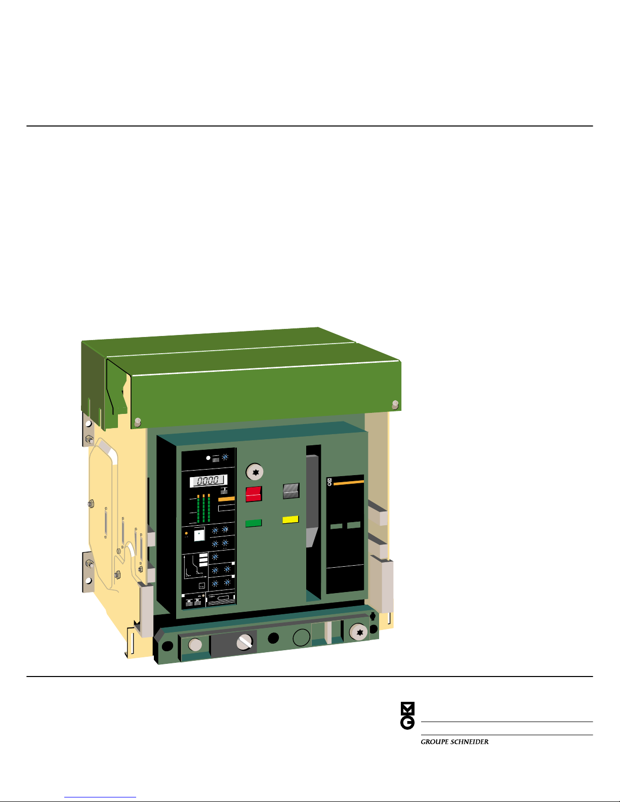
Masterpact
installation
instructions
universal power
breaker
TM
O
push OFF
MERLIN GERIN
MP20
H1
m
a
s
te
rp
a
c
t
connected
test
disconnected
O OPEN
discharged
I
push ON
circuit breaker
3 pole
600V 50/60Hz
frame size 2000A
suitable for continious operation
at 100% rating in a minimum cubical
space H17.5 by W21 by D14.1/4 inches
ventilation is not required
interrupting rating
max RMS sym amps
Volts
240
480
600
short time rating 75KA
Amps
75K
75K
75K
IE
C
9
5
7
-
2
6
9
0
V
5
0
/6
0
H
z
in
te
r
r
u
p
tin
g
r
a
tin
g
Ic
u
3
8
0
/4
4
0
V
7
5
K
A
6
6
0
V
7
5
K
A
I
c
u
3
8
0
/4
4
0
V
7
5
K
A
6
6
0
V
7
5
K
A
s
h
o
r
t tim
e
r
a
tin
g
Ic
w
=
7
5
K
A
0
.5
s
e
c
.
push to reset
I
I1 I2
I3
90%
50%
20%
STR 58 U
Ir
90
105
%
Ir
.
8
8
.
9
.
9
2
.
9
5
.
9
8
1
.
8
.
8
5
xIo
Im
tm
3
4
5
6
8
1
0
1
.
5
2
xIo
.
3
.
4.
3
.
1
.
1
.
2
o
n
I
2
t
o
f
f
.
2
0
I
r
f
a
u
lt
t
r
I
m
f
a
u
lt
t
m
I
f
a
u
lt
I
h
t
h
t
i
test
+ S
–
– T +
T
F
Ih
th
4
0
0
5
0
0
6
0
0
8
0
0
1
0
0
0
1
2
0
0
2
5
0
3
2
0
A
.
3
.
4.4
.
2
.
1
.
2
o
n
I
2
t
o
f
f
.
3
.
1
I
o
f
f
2
xIn
Ir :
Im
:
th :
I
I
GL
I
G
L
L
G
L
I
G
o
f
f
reset V
tr
6
0
1
2
0
2
4
0
4
8
0
1
5
3
0
a
t
1
,
5
I
r
4
6
8
1
2
1
7
2
2
Ic1 Ic2
.
8
6
.
9
.
9
3
.
9
5
.
9
8
1
.
8
.
8
5
.
7
.
8.
8
5
.
9
5
.
5
.
6
x
I
r
.
9
1
R
x
I
r
test
Io=3000A
c
a
t
.
n
o
.
5
4
7
7
5
f
o
r
m
a
s
t
e
r
p
a
c
t
w
i
t
h
s
e
n
s
o
r
s
I
n
=
6
0
0
0
A
E
6
3
3
3
5
U
N
D
.
L
A
B
. O
L
is
t
.
C
I
R
C
U
IT
B
R
E
A
K
E
R
D
o
l
e
s
.
Is
s
u
e
N
°
L
M
-
8
7
9
2
0
0
0
0
0
MERLIN GERIN
mastering electrical power
Page 2

689 994B - 15/10/94
1MERLIN GERIN
Masterpact MP-MC circuit breaker
TM
page
table of contents
installation
introduction 2
tools needed 2
recommendation for storing 2
identifying your Masterpact 3
unpacking 4
handling 6
attaching rear terminals 9
control wiring 11
operation
disconnecting instructions 13
installing the breaker in its stationary assembly 15
connecting instructions 16
charging instructions 17
closing instructions 17
opening instructions 17
resetting instructions 17
locking 18
refer to technical manual for :
■ control units
■ time-current curves
■ wiring diagrams
■ dimensions
■ maintenance
■ endurances
Page 3

Masterpact MP-MC circuit breaker
689 994B - 15/10/94
MERLIN GERIN2
TM
introduction
Instructions are to be followed when
receiving the breaker and before installing it.
tools needed
■ hex key wrenches
■ straight blade scewdriver (large and
small)
■ wire stripper
recommendations for storing
it is not recommended to store the breakers
in corrosive or salt laden environment.
Temperature limits :
from -60°F (-50°C) min to +160°F
(+70°C)max
Breaker status :
■ main contacts open
■ spring discharged
■ connected position
Do not store breaker without its original
shipping carton or any protective covering.
2
Stacking :
maximum permitted :
MP08 to MP30
MP40 to MP63
Page 4

689 994B - 15/10/94
3MERLIN GERIN
Masterpact MP-MC circuit breaker
TM
3
identifying your Masterpact
location of markingsTM
circuit breaker frame
stationary assembly
electrical accesories
identification label
(fixed mounting)
name label giving rating,
interrupting ratings
and rated voltage
order number - position - date
standard or specific diagram
no.
sensor rating
instantaneous pickup
electrical accesories
identification label
frame size
standard or specific diagram no.
order number - position - date
Page 5

Masterpact MP-MC circuit breaker
689 994B - 15/10/94
MERLIN GERIN4
TM
unpacking
MP08 to MP30
Breakers are screwed on their palett by
means of 4 bolts.
With drawout mounting, it is necessary to
withdraw and remove the breaker to have
access to the bolts.
fixed mounted
4
drawout mounted
disconnect the breaker (see page 12)
and remove it from its stationary assembly
(see page 13)
remove bolts, nuts and washers
drawout mounted without stationary assembly
pull the two handgrips to extract the breaker
remove the four bolts
remove the 4 shipping bolts
breaker is delivered upside down. Place
another palett next to shipping palett. Rotate
breaker onto terminals, then onto its bottom
on second palett
Page 6

689 994B - 15/10/94
5MERLIN GERIN
Masterpact MP-MC circuit breaker
TM
5
unpacking (cont'd)
MP08 to MP30
stationary assembly only
MP40 to MP63 drawout mounted
∂ remove the 4 shipping bolts
∑
position another wooden palett and rotate the frame
∏ remove the plastic
caps
breaker is delivered upside down. Place
another palett next to shipping palett. Rotate
breaker onto terminals, then onto its bottom
on second palett
circuit breaker frame
remove the 4 shipping bolts
stationary assembly
remove the tape holding the clusters (if any)
Page 7

Masterpact MP-MC circuit breaker
689 994B - 15/10/94
MERLIN GERIN6
TM
frame alone
handling
MP08 to MP30 - MC08 to MC20
The Masterpact frame and its stationary
assembly are provided with lateral handles
in order to facilitate lifting.
Before handling it is suggested to remove
the breaker from its stationary assembly.
See page 13 for operation.
External or overhead lifting device can use
the lateral handles for lifting the circuit
breaker as shown.
Weights (lbs/kg)
stationary frame terminals
assembly
MP08 51 /
23
102 /
46
13 / 6 ➀
MP12 51 /
23
102 /
46
13 / 6 ➀
MP16 51 /
23
102 /
46
13 /
6
MP20 60 /
27
121 /
55
36 /
16
MP25 110 /
50
176 /
80
89 /
40
MP30 110 /
50
176 /
80
89 /
40
MC08 51 /
23
102 /
46
13 /
6
➀
MC16 51 /
23
102 /
46
13 /
6
MC20 60 /
27
121 /
55
36 /
16
➀ optional terminals
using the lateral handles
frame alone
caution:
to avoid damage to the stationary assembly
do not let the forks of the fork lift protrude
past the rear of the breaker.
stationary assembly alone
using a lifting sling
slings :
.40 dia max.
Ø 10 mm max.
frame alone
stationary assembly alone
using a fork lift
Page 8

689 994B - 15/10/94
7MERLIN GERIN
Masterpact MP-MC circuit breaker
TM
handling (cont'd)
MC32
An external or overhead lifting device can
use the lateral handles for lifting the circuit
breaker as shown.
Weights (lbs/kg)
stationary frame
assembly
MC32 254 /
115
198 /
90
frame alone (compensation bar not supplied-hooks can be supplied on request)
stationary assembly alone (compensation bar not supplied-hooks can be supplied on request)
using a lifting sling
slings :
.40 dia max.
Ø 10 mm max.
stationary assembly alone
caution:
lift the stationary assembly enough to avoid
any shock between the load terminals and
the cubicle cell.
using a fork lift
2 slings : .40 dia max.
Ø 10 mm max.
1 sling : .40 dia max. 58.8 long max.
Ø 10 mm max. lg = 1500 mm max.
Page 9

Masterpact MP-MC circuit breaker
689 994B - 15/10/94
MERLIN GERIN8
TM
30" min.
800mm min.
handling (cont'd)
MP40 to MP63
An external or overhead lifting device can
use the lateral handles for lifting the circuit
breaker as shown.
Weights (lbs/kg)
stationary frame terminals
assembly
MP40 198 /
90
264 /
120
88 /
40
➀
MP50 198 /
90
264 /
120
177 /
80
MP63 242 /
110
308 /
140
177 /
80
➀ optional terminals
7
using a lifting sling
slings :
.40 dia max.
Ø 10mm max.
frame alone
stationary assembly alone
using a fork lift
frame alone
caution:
to avoid damage to the stationary assembly
do not let the forks of the fork lift protrude
past the rear of the breaker.
stationary assembly alone
caution:
to avoid capsizing the stationary assembly
place a chock as shown. Remove it as soon
as the ends of forks lean on the cubicle floor.
.
30" min.
800mm min.
2"
50 mm
1,2"
30 mm
Page 10

689 994B - 15/10/94
9MERLIN GERIN
Masterpact MP-MC circuit breaker
TM
8
drawout mounted
drawout mounted
drawout mounted
MP08 - MP12 - MP16
fixed mounted
MP20
fixed mounted
MP25 - MP30
fixed mounted
TM
screws M10, 60mm long
11/16 hex head wrench may be used
attaching rear terminals
The terminals provided with the Masterpact
shall be mounted as indicated below :
MP08 - MP20
screws M10, 60mm long
tightening torque = 375 lb.in.
11/16 hex head wrench may be used
MP25 - MP30
fixed mounted
drawout mounted
Page 11

Masterpact MP-MC circuit breaker
689 994B - 15/10/94
MERLIN GERIN10
TM
attaching rear terminals
(cont'd)
MC32
drawout mounted
MP40 - MC40
drawout mounted
MP40
fixed mounted
oror
MP50 - MP63 - MC50
drawout mounted
MP50
fixed mounted
Page 12

689 994B - 15/10/94
11MERLIN GERIN
Masterpact MP-MC circuit breaker
TM
1
control wiring
Each terminal may be connected by one
stranded copper wire 18 to 14 AWG (0.6 to
2.5 mm2)
Cable strip length : 3/8" /
9mm
fixed mounting
1 install the connector
2 remove the transparent shield
3 connect the control wires according to
the wiring diagrams shown on the label and
using a small screwdriver
4 replace the transparent cover
warning : do not route the control wires
close to the arc chutes
3
4
2
10
Page 13

Masterpact MP-MC circuit breaker
689 994B - 15/10/94
MERLIN GERIN12
TM
control wiring (cont'd)
drawout mounting
1 remove the front terminal cover
2 determine the terminal number ➀
according to the wiring label ➁
3 connect the control wires using a small
screwdriver and replace the front terminal
cover
4 warning : do not route the control wires
close to the arc chutes
1
11
2
3
4
location of terminals
note : Z = Z - W Control unit (left hand side) Accessories (right hand side)
Page 14

689 994B - 15/10/94
13MERLIN GERIN
Masterpact MP-MC circuit breaker
TM
12
disconnecting
and connecting instructions
All Masterpact circuit breakers have four
drawout positions and can be operated in
these four positions. The circuit breaker is
captive in all positions except "withdrawn".
To connect or disconnect the Masterpact
circuit breaker, first insert the of racking
crank.
Insertion of the racking crank can be
prevented by the following stationary
assembly accessories:
■ padlock
■ key-lock
■ racking interlock
note : Disconnecting and connecting
instructions are summarized on a sticker
provided with the installation instructions .
The sticker must be affixed to the door of the
CONNECTED position
TEST position
DISCONNECTED position
WITHDRAWN position
cubicle .■ In the CONNECTED
position, the primary and secondary
disconnecting terminals are engaged, and
the circuit breaker is ready for service.
■ In the TEST position, the primary
terminals are disengaged; however, control
contacts are connected to permit operation
of the circuit breaker. The TEST position is
used for testing circuit breaker operation and
control system functions as provided. In this
position, the circuit breaker is not suitable for
internal inspection or any maintenance
function.
■ In the DISCONNECTED position, the
primary and secondary disconnect terminals
are disengaged and separated by a safe
distance from the corresponding stationary
terminals
■ In the WITHDRAWN position, both
primary and secondary contacts are
disconneted. The circuit breaker may be
removed for complete accessibility.
note: a racking crank maintened inserted or
breaker not completely disconnected
prevents the extraction of the right rail.
notes :
■ a closed circuit breaker is automatically
opened prior to being connected or
disconnected during a racking in or racking
out operation.
■ the circuit breaker may be operated in all
four positions.
Page 15

Masterpact MP-MC circuit breaker
689 994B - 15/10/94
MERLIN GERIN14
TM
1
2
disconnecting instructions
note: open the breaker before disconnecting
it. Otherwise it will open automatically during
disconnection.
3
5
13
1 remove the racking crank from its
storage hole and engage it in the racking
slot
note : in case of racking interlock, press the
"compartment door closed" sensor located at
the front of the drawout mechanism to
simulate a closed door.
2 to reach the test position then
disconnected position turn the racking crank
anticlockwise until the test and disconnected
indication are shown on the position
indicator
3 caution : The racking handle must be
removed before pulling out the breaker,
otherwise the right rail will not fully extend
4 pull the two handgrips to extract the
breakers
5 use the two lateral handles to remove
the frame from its stationary assembly. See
other means of handling page 6
4
Page 16

689 994B - 15/10/94
15MERLIN GERIN
Masterpact MP-MC circuit breaker
TM
1
2
3
14
installating the breaker in
its stationary assembly
note : a racking handle remaining inserted
in its racking slot or a breaker not fully
disconnected prevents the extraction of the
right rail
1 pull the two extension rails by their
handles
2 install the breaker on the two extension
rails making sure that the four breaker
supports located on the two sides of the
circuit breaker are correctly engaged in the
slots. See page 6 for other means of
handling
3 to move the breaker from the WITHDRAWN position to the DISCONNECTED
position, push the breaker into the stationary
assembly until it stops.
As a safety feature, the racking crank cannot
be engaged if the breaker is not in the
DISCONNECTED position.
caution : do not press on the control unit
while pushing the breaker in.
Page 17

Masterpact MP-MC circuit breaker
689 994B - 15/10/94
MERLIN GERIN16
TM
1
32
15
connecting instructions
1 engage racking crank into its racking slot
note : the operation is possible only if :
❑breaker is in DISCONNECTED position
❑drawout mechanism padlocks have been
removed
❑Kirk key lock has been unlocked
❑compartment door is closed
note : in case of racking interlock, press the
"compartment door closed" sensor located at
the front of the drawout mechanism to
simulate a closed door
2 turn the racking crank clockwise until the
CONNECTED position is reached on the
position indicator
warning : as the fully connected position is
neared, more force will be necessary to turn
the crank. Continue cranking until two "click"
sounds are heard (locking the breaker in the
connected position)
3 remove the racking crank and put it back
in its storage hole
Page 18

689 994B - 15/10/94
17MERLIN GERIN
Masterpact MP-MC circuit breaker
TM
charging instructions
All basic breaker and drawout operations
can be performed from the front of the
breaker.
Suitable electrical and mechanical interlocks
are provided to prevent incorrect operation
of the breaker. Manually operated breakers
have multiple charge-close provisions which
allow the following possible operating
sequence : charge-close-recharge-openclose-open.
To manually charge an electrically or
manually operated breaker, push or pull
down on the charging handle. The handle is
shaped to make manual charging easy,
when the breaker is located in either a low or
high position within a switchboard enclosure.
Six full strokes can be used. When the
spring is fully charged, the yellow "charged"
indicator will appear in the stored energy
window on the breaker front cover.
When the mechanism is fully charged, the
handle stops and will return to normal
position when released.
Manually Electrically
closing instructions
All that is required to close the breaker
locally is to push the mechanical "Push-toclose" pushbutton. Pre-charged breakers
may be closed remotely via a spring release
solenoïd which is standard for electrically
operated breakers and optional for manually
operated breakers.
Before attempting to close the breaker
locally, the yellow stored energy window
indicator must read "charged".
note :
■ The closing coil (XF) withstands a
continuous voltage, providing antipumping
function. If the breaker is not ready to close
when the closing order is intended, inhibit it
and try again as soon as the breaker is
ready to close
■ to inhibit the antipumping function, wire in
series the ready-to-close switch (terminals
251 - 252) with the closing coil.
opening instructions
Opening the breaker locally is accomplished
with the mechanical "Push to open"
pushbutton on the breaker front cover .
Breakers may be opened remotely via either
a shunt trip or an undervoltage trip device
depending upon the application require-
ments.
16
resetting instructions
The mechanical fault indicator indicates
that an overcurrent has occured and
prevents reclosure of the circuit breaker until
reset.
caution : in case of tripping due to overcurrent or ground fault, the fault must be
cleared before any attempt of resetting
Breaker can be closed only if :
■ it is opened
■ charged
■ pop-out type fault indicator is correcly
reset
■ no opening order is intended
Page 19

123456789101112131415161718
19 20 21 22 23 20 20 20 20
page 2
tools needed
■ hex key wrenches
■ straight blade scewdriver (large and
small)
■ wire stripper
page 5
remove the tape holding the clusters (if any)
page 6
handling
MP08 to MP30 - MC08 to MC20
The Masterpact frame and its stationary
assembly are provided with lateral handles
in order to facilitate lifting.
Before handling it is suggested to remove
the breaker from its stationary assembly.
See page 13 for operation.
External or overhead lifting device can use
the lateral handles for lifting the circuit
breaker as shown.
page 7
rod .48 dia.
Ø 12 mm
Weights (lbs/kg)
stationary frame
assembly
MC32 254 /
115
198 /
90
2 slings : .40 dia max.
Ø 10 mm max.
1 sling : .40 dia max. 58.8 long max.
Ø 10 mm max. lg = 1500 mm max.
stationary assembly alone
caution:
lift the stationary assembly enough to avoid
any shock between the load terminals and
the cubicle cell.
page 9
screws M10, 60mm long
tightening torque = 375 lb.in.
11/16 hex head wrench may be used
screws M10, 60mm long
11/16 hex head wrench may be used
1 remove the racking crank from its
storage hole and engage it in the racking
slot
note : in case of racking interlock, press the
"compartment door closed" sensor located at
the front of the drawout mechanism to
simulate a closed door.
2 to reach the test position then
disconnected position turn the racking crank
anticlockwise until the test and disconnected
indication are shown on the position
indicator
3 caution : The racking handle must be
removed before pulling out the breaker,
otherwise the right rail will not fully extend
4 pull the two handgrips to extract the
breakers
5 use the two lateral handles to remove
the frame from its stationary assembly. See
other means of handling page 6
page 14
Shackle diameter : 1/4" to 5/16"
page 18
couverture
MERLIN GERIN
mastering electrical power
sommaire
8 9 10111213141516171819202020202020
Page 20

MERLIN GERIN
12
page 5
remove the tape holding the clusters (if any)
Page 21

MERLIN GERIN
18
Masterpact MP-MC circuit breaker
TM
■ by padlocking device (standard)
stationary assembly
■ by Kirk key lock (VSKC)
locking
■ padlocking using a device (VBP).
Access to opening ➀ and/or closing ➁ of
the circuit breaker can be prevented by a
padlock.
Shackle diameter : 1/4 to 5/16
circuit breaker frame
■ by Kirk lock (VSKA)
locking in open position :
➀ push the OFF button
➁ turn the lock
➂ remove the key
note : this locking inhibits the insertion of the racking handle. This will prevent racking the
breaker into its stationary assembly
Shackle diameter : 1/4" to 5/16"
note : locking in disconnected position or in
all positions : connected - test and disconnected (on request)
locking in the disconnected position :
➀ disconnect the breaker
➁ turn the lock
➂ remove the key
Page 22

MERLIN GERIN
19
Masterpact MP-MC circuit breaker
locking (cont'd)
Door
by door interlock (VDP)
Prevents the door from opening when the breaker is in the connected and test positions.
note : the hook can be mounted on either side.
To change location :
12
3
Page 23

MERLIN GERIN
20
Masterpact MP-MC circuit breaker
TM
locking (cont'd)
Shutters
by padlocking device
storage lock in closed
position position
lock in open padlocking
position
Spring charged
When the closing springs are charged, this interlock prevents the breaker from being disconnected by-catching it in its stationary assembly
Before pulling out the circuit breaker, discharge the spring by pressing the ON pushbutton then
the OFF pushbutton
caution : not suitable with undervoltage trip device
Page 24

Idaho
Boise ........................ (208) 376-0552
Idaho Falls ............... (208) 522-6274
Illinois
Champaign............... (217) 356-0211
Lombard (Chicago) .. (708) 916-9550
Peoria....................... (309) 688-0508
Rockford................... (815) 965-2060
Springfield
(Sangamon) ............. (217) 546-1477
Indiana
Evansville .................(812) 493-3900
Fort Wayne .............. (219) 483-3194
Highland (Hammond) (219) 972-9600
................................. (312) 721-6031
Indianapolis .............. (317) 469-8800
Mishawaka (So. Bend)
(219) 259-8521
Iowa
Cedar Rapids ........... (319) 366-0736
Davenport ................ (319) 386-6897
Des moines .............. (515) 280-1011
Kansas
Shawnee (Kansas City)
(913) 599-3000
Wichita ..................... (316) 264-9338
Kentucky
Lexington ................. (606) 278-0308
Louisville .................. (502) 425-8363
Paducah ................... (502) 554-5515
Louisiana
Baton Rouge ............ (504) 924-9923
Metairie (New Orleans)
(504) 837-9022
Shreveport ............... (318) 865-4267
Maine
Portland.................... (207) 774-1409
Maryland
Easton ...................... (410) 819-0001
Hagerstown .............. (301) 739-5760
Towson (Baltimore) .. (410) 337-8448
Massachusetts
Baintree (Boston) ..... (617) 848-1110
Michigan
Flint .......................... (313) 230-6622
Grand Rapids ........... (616) 459-3529
Kalamazoo ............... (616) 342-2117
Lansing .................... (517) 337-2835
Traverse City............ (616) 946-3773
Troy (Detroit) ............ (313) 680-4444
Minnesota
Duluth....................... (218) 723-1010
Plymouth
(Minneapolis) ........... (612) 476-6909
Mississipi
Jackson .................... (601) 982-1031
Tupelo ...................... (601) 842-3398
Missouri
Jefferson City ........... (314) 893-4426
Springfield ................ (417) 887-2307
St. Louis ................... (314) 849-6330
Montana
Billings...................... (406) 252-5587
Nebraska
Omaha ..................... (402) 330-3753
Nevada
Las Vegas ................ (702) 798-7811
New Hampshire
Manchester .............. (603) 668-1204
New Jersey
Pine Brook
(New Jersey) ............ (201) 575-7000
New Mexico
Albuquerque............. (505) 828-1018
New York
Albany ...................... (518) 452-2590
Binghamton .............. (607) 723-7337
Buffalo ...................... (716) 836-5800
Mineola
(New York City) ........ (516) 248-0080
Rochester................. (716) 424-4171
Syracuse .................. (315) 455-5324
White Plains ............. (914) 428-7790
North Carolina
Asheville................... (704) 254-5987
Charlotte .................. (704) 529-1533
Greensboro .............. (919) 292-8995
Greenville ................. (919) 756-2117
Raleigh ..................... (919) 782-1338
Wrightsville Beach
(Wilmington) ............. (919) 256-9956
North Dakota
Fargo........................ (701) 235-7223
Ohio
Brecksville (Cleveland)
(216) 526-9070
Cincinnati ................. (513) 793-6811
Columbus ................. (614) 486-4329
Dayton...................... (513) 297-7771
Toledo ...................... (419) 535-1293
Oklahoma
Oklahoma City ......... (405) 942-7334
Tulsa ........................ (918) 622-2800
Oregon
Portland.................... (503) 684-1090
Pennsylvania
Altoona ..................... (814) 942-1966
Bethlehem (Allentown)
(215) 694-9600
Kingston (Wilkes-Barre)
(717) 288-1461
Media (Philadelphia) (215) 565-8750
Pittsburgh ................. (412) 921-3810
York (Harrisburg) ..... (717) 845-1041
Rhode Island
Cranston (Providence)
(401) 943-3380
South Carolina
Charleston................ (803) 556-0773
Columbia .................. (803) 799-8903
Greenville ................. (803) 288-6384
South Dakota
Sioux Falls ............... (605) 334-2151
Tenessee
Brentwood (Nashville)
(615) 371-8069
Chattanooga ............ (615) 877-1381
Kingsport .................. (615) 239-7948
Knoxville................... (615) 524-7477
Memphis .................. (901) 682-8866
Texas
Amarillo .................... (806) 372-1938
Austin ....................... (512) 346-7120
Beaumont................. (409) 866-7726
Corpus Christi .......... (512) 883-5566
Dallas/Ft.Worth ........ (817) 858-0001
El Paso..................... (915) 592-8813
Harlingen.................. (210) 423-1694
Houston.................... (713) 493-1300
Longview .................. (903) 297-1267
Lubbock ................... (806) 794-4754
Midland .................... (915) 694-8430
San Antonio ............. (512) 829-7771
Sherman .................. (903) 868-2720
Waco ........................ (817) 776-3432
Wichita Falls............. (817) 322-5589
Utah
Murray
(Salt Lake City) ........ (801) 266-2096
Vermont
See Manchester, NH
Virginia
Charlottesville .......... (804) 973-7069
Norfolk...................... (804) 461-1290
Richmond ................. (804) 285-7508
Roanoke................... (703) 989-1250
Washington
Mercer Island (Seattle)
(206) 232-9702
Spokane ................... (509) 535-3685
West Virginia
Barboursville
(Huntington) ............. (304) 736-8944
Charleston................ (304) 342-3211
Wisconsin
Green Bay ................ (414) 494-3313
Madison ................... (608) 271-2600
Milwaukee ................ (414) 359-0959
Wyoming
See Denver, CO
Pleasanton, CA ........ (415) 462-0986
Miami, FL ................. (305) 591-9716
White Plains, NY ...... (914) 682-0667
Smyrna, TN .............. (615) 459-5026
Houston, TX ............. (713) 493-1300
London ..................... (519) 434-4012
Mississauga ............. (416)678-7000
Moncton ................... (506) 587-0719
Montreal ................... (514) 697-4790
Ottawa...................... (613) 596-2190
Quebec City ............. (418) 682-6020
Saskatoon ................ (306) 242-0262
Sudbury.................... (705) 560-9516
Vancouver ................ (604) 436-0094
Windsor .................... (519) 966-7674
Winnipeg .................. (204) 632-4477
Mexico
Cancun..................... 52-988-49454
Coatzacoalcos ......... 52-921-24043
Guadalajara ............. 52-362-51633
Hermosillo ................ 52-621-24555
Juarez ...................... 52-16110032
Leon ......................... 52-471-23550
Merida ...................... 52-992-61723
Mexico City .............. 525-686-3000
Monterrey ................. 52-837-29845
Nuevo Laredo .......... 52-871-30010
Tampico ................... 52-122-84255
Tijuana ..................... 52-668-47704
Torreon .................... 52-172-00422
Veracruz................... 52-293-15677
Schneider Electric SA
united states
international
locations
other north
american
sales offices
Canada
Calgary..................... (403) 279-2100
Edmonton................. (403) 453-3561
Halifax ...................... (902) 450-5337
Hamilton ................... (416) 578-3398
sales offices
in the united states
Alabama
Birmingham .............. (205) 967-1110
Dothan ..................... (205) 793-2177
Huntsville ................. (205) 539-2465
Mobile ...................... (205) 342-7747
Montgomery ............. (205) 271-0230
Alaska
Anchorage................ (907) 278-6048
Arizona
Phoenix .................... (602) 231-8694
Tucson ..................... (602) 795-3600
Arkansas
Ft. Smith................... (501) 452-7312
Little Rock ................ (501) 225-3648
California
Bakersfield ............... (805) 833-1985
City of industry
(Los Angeles)........... (310) 699-7008
Fresno...................... (209) 268-6268
Pleasanton
(San Francisco)........ (510) 462-0986
Riverside .................. (714) 784-3661
Sacramento.............. (916) 369-2495
San Diego ................ (619) 569-8953
Stockton ................... (209) 944-5633
Ventura .................... (805) 658-2566
Colorado
Englewood (Denver) (303) 799-9003
Connecticut
Wetherfield (Hartford)(203) 529-7472
Delaware
Northern one-third see Philadelphia, PA
Southern two-thirds see Easton, MD
District of columbia
Rockville (Wash. D.C.)
(301) 921-0083
................................. (301) 921-2064
Florida
Altamonte Springs
(Orlando) .................. (407) 774-5151
Deerfield Beach
(Miami) ..................... (305) 698-9400
Ft. Myers .................. (813) 936-5573
Jacksonville.............. (904) 348-3150
Tallahassee.............. (904) 744-7881
Tampa...................... (813) 286-0227
Georgia
Columbus (Muscogee)
(706) 561-7825
Macon ...................... (912) 471-9033
Savannah................. (912) 356-9546
Smyrna (Atlanta) ...... (404) 333-3660
Hawaii
Honolulu................... (808) 422-0567
689 994A ind. B
We Respond
®
design by AMEG - DBTP - 12/94 - Poncet SA imprimeur
As standards, specifications and designs develop from time
to time, always ask for confirmation of the information given
in this publication.
 Loading...