

Page 1

Meridian 1
Meridian Link/Customer Controlled Routing
Installation and Upgrade Guide
Publication number: 553-3202-210
Product release: Meridian Link Release 5C/Customer Contolled Routing Release 3C
Document status: Standard 1.0
Date: October 1998
© 1998 Northern Telecom
All rights reserved
Printed in the United States of America
Northern Telecom reserves the right to make changes in equipment, design, or components as progress in
engineering or manufacturing may warrant.
Meridian 1, SL-1, and Nortel are trademarks of Northern Telecom. UNIX is a trademark of AT&T. Motorola is a
trademark of the Motorola Corporation. MVME products are trademarked by the Motorola Corporation.
Ethernet is a trademark of the Xerox Corporation. Reflection is a trademark of Walker Richer & Quinn, Inc.
DEC, VT220, VT320, and VT420 are trademarks of Digital Equipment Corporation. UDS is a trademark of
Motorola Incorporated.
Page 2

ii
553-3202-210 Standard October 1998
Page 3

Publication history
October 1998
Standard 1.0
iii
Meridian Link Release 5C/CCR Release 3C Installation and Upgrade Guide
Page 4

iv Publication history
553-3202-210 Standard October 1998
Page 5

Contents
v
About this guide xv
References xviii
Chapter 1: Meridian Link/CCR 1
Co-residency overview 1
Keycode 4
Ethernet LAN-based PC 5
Module address and module name 7
Chapter 2: Overview of Meridian Link 9
Meridian Link application 13
Operating system overview 13
New with Meridian Link Release 5C 14
Link overview 15
AML and the Host Link (or Meridian Link) 15
Meridian Mail Link 16
Diagnostic tools 16
System console and maintenance console 17
Meridian Link administration and maintenance 17
Host support service requirements 18
Meridian 1 18
Hardware overview 18
Software overview 21
Host 23
Meridian Link service requirements 23
Host connection considerations 24
Ethernet LAN-based host 24
Meridian Mail software requirements 26
Operations, Administration, and Maintenance (OA&M) 26
Meridian Link Release 5C/CCR Release 3C Installation and Upgrade Guide
Page 6

vi Contents
Chapter 3: Overview of Customer Controlled
Routing 27
CCR application 30
An example of CCR call handling 30
Key CCR concepts 31
Operating system 31
New with CCR Release 3C 32
Application Module Link 32
Diagnostic tools 32
System console and maintenance console 32
CCR administration and maintenance 33
Consoles/printers 33
Meridian 1 34
Hardware overview 34
Software overview 36
Chapter 4: Meridian Link/CCR hardware 39
IPE Module 39
Connector panel and I/O connectors (Option 11) 42
Connector panel and I/O connectors (Options 21Ð81) 45
IPE Module components 46
Application Module 50
AEM power 53
Application Module components 54
Single board computer card (Application Module) 58
MVME333-2 X.25 communication controller (XCC) card 66
MVME332XT or MVME332XTS asynchronous
communication controller (ACC) card 68
Transition cards 70
P2 adapter board 78
Power supply 79
Disk/tape unit 80
VME bus backplane (Application Module) 82
Power sense card (Application Module) 82
I/O connectors (Application Module) 82
Input/output panel 83
553-3202-210 Standard October 1998
Page 7

Contents vii
Chapter 5: Hardware installation overview 87
Preparing for installation 87
Installing an IPE Module or an Application Module 88
Chapter 6: Site survey/installation checklist 91
General information 91
End user 91
Distributor 92
Nortel support representative 92
Delivery information 93
Customer site 93
Freight company 93
Loading equipment required 94
Meridian 1 software checklists 94
Requirements for Meridian Link 95
Requirements for CCR 97
Requirements for Meridian Mail to support Meridian Link 99
Meridian Mail hardware checklist to support Meridian Link 100
IPE Module and Application Module: Meridian Link/CCR
software 101
IPE Module and Application Module: Meridian Link/CCR
software current status 101
Changes to IPE Module and Application Module 101
Meridian Link/CCR tapes and keycode 102
Documentation 103
Hardware 104
Equipment room information 105
Power and ground considerations 106
Equipment cabling 107
Input/output device cabling 107
Peripheral device cabling 108
Telephony connections 111
Equipment room cooling conditions 112
Additional considerations 112
Comments and recommendations 113
Meridian Link Release 5C/CCR Release 3C Installation and Upgrade Guide
Page 8

viii Contents
Chapter 7: Unpack and inspect hardware 115
Receiving the IPE Module and Application Module
components 116
Unpacking the IPE Module and Application Module
components 117
Chapter 8: Hardware installation procedures 119
Installing the IPE Module 120
Installing the Application Module 125
Installing the power supply and disk/tape unit 127
Checking the card option settings (Application Module) 129
Installing an NTAK02 SDI/DCH card 142
Installing an ESDI or MSDL card 145
Chapter 9: Meridian Link/CCR interface cabling 151
IPE Module cabling 151
IPE Module cables 151
External I/O cables 154
External I/O cable pinouts (IPE Module) 155
Cabling the Option 11 IPE Module to external equipment 177
Cabling to external equipment 177
Backplane cable rerouting for Options 21Ð81 CE/PE and IPE
backplanes 185
Backplane cable rerouting for the NT8D11 CE/PE Module
backplane 187
Backplane cable rerouting for NT8D37 IPE Module 195
Cabling the Options 21Ð81 IPE Module to external equipment 209
Application Module cabling 216
Power cables 216
Input/output cables 219
Cabling the Application Module to external equipment 227
Installing Ethernet LAN support 256
553-3202-210 Standard October 1998
Page 9

Contents ix
Chapter 10: Installing peripheral devices 261
VT220, VT320, and VT420 terminals 261
Personal computer running Reflection 4+ 266
Meridian Terminal Emulator (MTE 8) 267
Dot-matrix printer switch settings 268
LaserJet series II printer switch settings 269
LaserJet series III printer switch settings 270
LaserJet series IV printer switch settings 271
DeskJet and DeskJet 500 printer switch settings 272
Chapter 11: Peripheral device cabling interface 273
DCE and DTE connections 273
Using an A/B switchbox to share system consoles 276
Connecting the A/B switchbox 276
Using the A/B switchbox to switch applications 277
Modems 278
Limited-distance modem 278
USRobotics Sportster modem 279
Gandalf LDS 120E limited-distance modem 280
Dial-up modem 282
Chapter 12: Meridian 1 configuration 293
Conventional notation 293
Configuration overview 295
Configuring the VSID, HSID, and AML prompts 296
Configure ESDI port (X11 Release 17) 299
Options 21Ð81 ESDI configuration 299
Enable ESDI port (X81 phase 7 or X11 Release 17) 302
Configure ESDI or MSDL port (X11 Release 18 or later) 305
Option 11 ESDI configuration 305
Option 21Ð81 ESDI or MSDL configuration 308
Enable ESDI or MSDL port (X11 Release 18 or later) 312
Configure SDI port for conshare (X11 Release 17) 315
Configure SDI port for conshare (X11 Release 18 or later) 317
Enable SDI port 318
Configuring DNIS to use auto-terminating trunks 319
LD 15ÑCustomer data block 319
LD 16ÑRoute data block 320
LD 14ÑTrunk data block 322
Configuring DNIS to use Incoming Digit Conversion 324
Meridian Link Release 5C/CCR Release 3C Installation and Upgrade Guide
Page 10

x Contents
Configure devices for status change host notification 330
Define status message groups 333
Assign telephones to status message groups (Meridian
Link) 335
Configure ACD DNs 344
Configure Control DNs (CCR) 346
Configuring a Phantom Loop 349
Configuring a Phantom Superloop 350
Creating a Phantom Set 351
Configuring Dual VAS ID 353
Traffic statistics 354
Chapter 13: Meridian Mail configuration 355
Meridian Mail call processing 357
Configuring Meridian 1 for Meridian Mail 358
Creating a Meridian Mail ACD queue 358
Defining virtual agent DNs for voice channels 360
Configuring Meridian Mail for Host Enhanced Voice
Processing (HEVP) 363
Adding the Meridian Mail ACD DN to the Voice Service DN
(VSDN) Table 363
Defining voice channels in the Channel Allocation Table
(CAT) 366
Defining a new mailbox for the application 368
Chapter 14: Software installation, upgrade, and
update procedures 371
To configure the software after installing a new IPE Module
or Application Module 375
Section 1: To upgrade Meridian Link from Release 2 to
Release 5C or Co-residency using a Release 2 backup
tape 376
Section 2: To upgrade Meridian Link from Release 3 to
Release 5C or Co-residency using a Release 3 backup
tape 377
Section 3: To upgrade Meridian Link from Release 4 to
Release 5C 378
Section 4: To upgrade Meridian Link from Release 4 to 379
Section 5: To upgrade Meridian Link from Release 4B to
Release 5C 380
553-3202-210 Standard October 1998
Page 11

Contents xi
Section 6: To upgrade Meridian Link from Release 4B to
Release 5C and Co-residency 381
Section 7: To update Meridian Link from Release 5 to
Release 5C 382
Section 8: To update Meridian Link from Release 5 to 382
Section 9: To upgrade CCR from Release 2 to Release 3C
or 383
Section 10: To update CCR from Release 3 to Release 3C 384
Section 11: To update CCR from Release 3 to Co-
residency 384
Section 12: To update CCR Release 3B to Release 3C 385
sSection 13: To update CCR from Release 3B to Co-
residency 385
Section 14: To update Co-residency from one issue to
another issue of the same release 385
Section 15: Activating or de-activating a Meridian Link or
CCR feature 386
Section 16: To install or reinstall the software from tape 386
Procedure 1: Application configuration and start-up 388
Procedure 2: Start the update process 397
Procedure 3: Load application software from tape 399
Procedure 4: Power down the IPE Module or the
Application Module 411
Procedure 5: Load the operating system tape on an
Application Module with an MVME147 card 413
Procedure 6: Load the operating system tape on an IPE
Module or an Application Module with an MVME167
card 429
Procedure 7: Reboot and go through setup 448
Procedure 8: Load the application software from tape 458
Procedure 9: Restore configuration files and data files from
the backup tape 471
Procedure 10: Verify the installation 475
Procedure 11: Back up configuration files and data files 476
Meridian Link Release 5C/CCR Release 3C Installation and Upgrade Guide
Page 12

xii Contents
Chapter 15: Link configuration 479
Default configuration 479
Link 0ÑApplication Module Link 479
Link 1ÑX.25 protocol 480
Link 1ÑTCP/IP host link protocol 481
Link 2ÑMeridian Mail Link 481
Changing your configuration 482
Procedure 12: Verifying the link status 483
Procedure 13: Changing AML (link 0) parameters 484
Procedure 14: Changing Meridian Link (link 1) parameters 489
Procedure 15: Changing Meridian Mail Link (link 2)
parameters 497
Procedure 16: Replacing the default configuration file 499
Procedure 17: Creating a configuration file 500
Chapter 16: Additional application configuration503
Procedure 18: Turn off auto-start 505
Procedure 19: Change the Meridian 1 customer number 506
Procedure 20: Schedule regular backups 507
Procedure 21: Change the default system languages 509
Procedure 22: Configure terminal ports 511
Procedure 23: Configure printer ports 513
Chapter 17: Hardware upgrade 517
To upgrade an Application Module SBC card from an
MVME147 card to an MVME167 card 517
To upgrade an Option 11 IPE Module to an Options 21Ð81
IPE Module 517
Procedure 24: Software powerdown 518
Procedure 25: Hardware powerdown 520
Procedure 26: Upgrading the Application Module from an
MVME147 card to an MVME167 card 521
Procedure 27: Upgrading an Option 11 to an Options
21Ð81 IPE Module 522
Procedure 28: Installing the cables for Ethernet LAN
support (Application Module) 524
Procedure 29: Installing the MVME332XT or
MVME332XTS ACC card 526
553-3202-210 Standard October 1998
Page 13

Contents xiii
Chapter 18: Acceptance testing 527
Meridian Link/CCR 527
Meridian Mail 529
Using Edit Voice to create voice segment files 529
Recording and trimming voice segments 530
Creating a header file 530
Using Edit Voice for the first time 531
Example of customer account balance query 531
Chapter 19: Single Terminal Access 533
Hardware and software requirements 533
Before you begin 534
Setting up STA 537
Chapter 20: Ordering 545
List of terms 553
Index 559
Meridian Link Release 5C/CCR Release 3C Installation and Upgrade Guide
Page 14

xiv Contents
553-3202-210 Standard October 1998
Page 15

About this guide
This document details the steps and procedures required to successfully
install the hardware and software for your Meridian Link and/or Customer
Controlled Routing (CCR) system.
Meridian Link enables the call and voice processing capabilities of a
Meridian 1 system to be integrated with a customerÕs computer-based
business applications. Through Meridian Link, an application can place and
answer calls, route calls, and even implement Interactive Voice Response
applications.
CCR enables you to control and route Automatic Call Distribution (ACD)
calls entering your Meridian 1 system. For example, for an incoming ACD
call, you can provide a specific recorded announcement, music, or both,
before assigning the call to an agent.
The hardware for both applications can be either an Intelligent Peripheral
Equipment (IPE) Module or an Application Module.
The software consists of a base operating system (BOS) and application
programs, referred to as the Meridian Applications.
xv
This guide contains the following main areas of information:
Chapter 1: Meridian Link/CCR co-residency The first chapter provides an
overview of Meridian Link/CCR co-residency and describes the keycode
and the Ethernet LAN-based PC features.
Chapter 2: Overview of Meridian Link This chapter provides an overview
of Meridian Link, describes its concepts, and lists required hardware and
software.
Meridian Link Release 5C/CCR Release 3C Installation and Upgrade Guide
Page 16

xvi About this guide
Chapter 3: Overview of Customer Controlled Routing This chapter
provides an overview of CCR, describes its concepts, and lists required
hardware and software.
Chapter 4: Meridian Link/CCR hardware This chapter provides an
overview of hardware components.
Chapter 5: Hardware installation overview This chapter lists the tools and
provides tables to describe the installation of an IPE Module or an
Application Module.
Note: If you intend to install an IPE Module or an Application
Module, refer to Table 11 (IPE Module) or Table 12 (Application
Module) in this chapter.
Chapter 6: Site survey/installation checklist This chapter provides a
checklist to ensure that all hardware and software requirements are met for a
successful installation.
Chapter 7: Unpack and inspect hardware This chapter provides
information on receiving, unpacking, and inspecting the IPE Module and
Application Module hardware components.
Chapter 8: Hardware installation procedures This chapter contains all of
the main hardware installation procedures, with references to surrounding
chapters for further information.
Chapter 9: Meridian Link/CCR interface cabling This chapter describes
the cabling requirements. Two following chapters describe how to set up
terminals, and how to configure the Meridian 1 system.
Chapter 10: Installing peripheral devices This chapter describes the
procedures for how to set up and configure video display terminals and
printers supported by the Meridian Link and CCR appplications.
Chapter 11: Peripheral device cabling interface This chapter provides
information on installing and configuring modems and the A/B switchbox.
Chapter 12: Meridian 1 configuration for Meridian Link/CCR This
chapter shows how to use various software programs to configure the
Meridian 1 to support Meridian Link and CCR.
553-3202-210 Standard October 1998
Page 17

About this guide xvii
Chapter 13: Meridian Mail configuration This chapter shows how to
configure the Meridian 1 to support Meridian Mail.
Chapter 14: Software installation, upgrade, and update procedures
This chapter describes procedures for
¥ configuring the IPE Module and the Application Module, along with
start-up information
¥ upgrading the software from one release to another (for example, from
Meridian Link Release 4B to Release 5C)
¥ updating the software from one issue of a release to another issue of the
same release (for example, from issue 4.17 to issue 4.25)
¥ reinstalling software (for example, after replacing a hard disk)
Chapter 15: Link configuration This chapter describes the configuration
procedures for the links used by the applications.
Chapter 16: Additional application configuration This chapter describes
the procedures used for scheduling backups and configuring terminal and
printer ports.
Chapter 17: Hardware upgrade This chapter describes the procedures for
upgrading from an MVME147 card to an MVME167 card and upgrading an
Option 11 IPE Module to an Options 21Ð81 IPE Module.
Chapter 18: Acceptance testing This chapter describes the various
acceptance tests you can perform.
Chapter 19: Single Terminal Access This chapter describes how to
configure the Meridian 1 system to support Single Terminal Access.
Chapter 20: Ordering This chapter lists field-replaceable items for both the
IPE Module and Application Module.
Note: The term ÒMeridian 1Ó is used throughout this document, and
refers to Meridian 1 and ÒMeridian 1-readyÓ systems (such as Meridian
SL-1 style cabinets that have been upgraded).
Meridian Link Release 5C/CCR Release 3C Installation and Upgrade Guide
Page 18

xviii About this guide
References
Refer to the following related documents:
¥ Application Equipment Module Installation Guide (NTP 553-3201-200)
¥ Application Module and Intelligent Peripheral Equipment Module
¥ Application Module and Intelligent Peripheral Equipment Module
¥ Meridian Link/Customer Controlled Routing Engineering Guide
¥ Customer Controlled Routing User Guide (P0747008)
Diagnostic and Maintenance Guide (NTP 553-3211-510)
Advanced Maintenance Guide (NTP 553-3211-512)
(NTP 553-3211-520)
553-3202-210 Standard October 1998
Page 19

Chapter 1: Meridian Link/CCR co-residency
Co-residency overview
With Meridian Link Release 5C and CCR Release 3C, you can install both
Meridian Link and CCR in a single IPE Module or Application Module.
You should be aware that both applications use the same CPU, RAM, and
hard disk, so you cannot expect the same performance from a
co-resident application as you would get from a stand alone application.
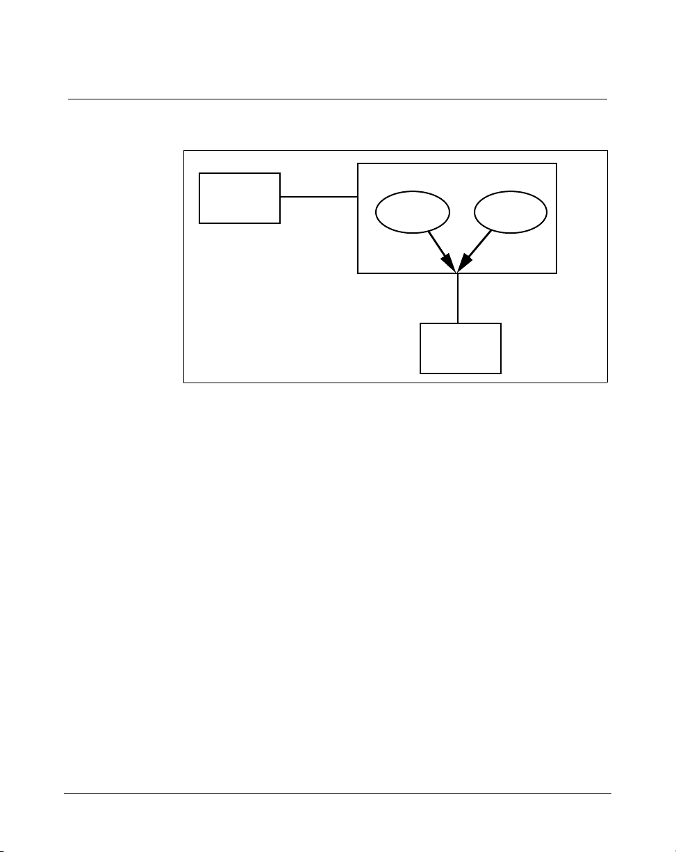
As shown in Figure 1, Meridian Link and CCR applications communicate
with the Meridian 1 through the same Application Module Link (AML), and
at the same time.
1
Meridian Link Release 5C/CCR Release 3C Installation and Upgrade Guide
Page 20
2 Chapter 1: Meridian Link/CCR co-residency
Figure 1
Meridian Link/CCR co-residency
Host
Host Link
IPE Module
Meridian
Link
CCR
AML
Meridian 1
553-3202-210 Standard October 1998
Page 21

Chapter 1: Meridian Link/CCR co-residency 3
This guide provides more detailed information on both the Meridian Link
and CCR applications in the following chapters:
¥ Chapter 2, ÒOverview of Meridian LinkÓ
¥ Chapter 3, ÒOverview of Customer Controlled RoutingÓ
If you intend to activate both Meridian Link and CCR in an Application
Module, the Application Module must have an MVME332XTS ACC card
and an NT6D51AA transition card installed. Refer to Chapter 4, ÒMeridian
Link/CCR hardwareÓ for descriptions of these cards.
If you intend to activate both Meridian Link and CCR in an IPE Module,
you should know that only two ports (7 and 8) will be available for CCR
terminals or printers. Port 6 will be used for the Host Link. However, you
can use LAN-based PCs as additional terminals. For more information, refer
to ÒEthernet LAN-based PCÓ later in this chapter.
Note: If you expect the maximum number of active CDN script
associations at any one time to be 20 or fewer, you should consider
installing CCR-S instead of the larger version (Large CCR). By doing
so, you will enhance the processing power available to Meridian Link
and CCR. Large CCR accommodates as many as 240 active CDN
script associations at any one time.
For more information about Meridian 1 configuration changes for coresident systems, refer to ÒConfiguring the VSID, HSID, and AML
promptsÓ in Chapter 12, ÒMeridian 1 Configuration for Meridian
Link/CCR.Ó
Meridian Link Release 5C/CCR Release 3C Installation and Upgrade Guide
Page 22

4 Chapter 1: Meridian Link/CCR co-residency
Keycode
IPE or Application Module software may or may not be pre-loaded:
¥ If the module is shipped to the United States, Europe, or Japan, the
software is likely to be already loaded.
¥ If the module is shipped to a Caribbean or Latin American location, to
Canada, or to the Asia Pacific region, the software may not be loaded.
If the software is preinstalled, a special keycode activates only the ordered
application or applications during installation. When the module is installed
at your site, you must enter a keycode to activate the correct application or
applications before you can configure the new module. You also need a
keycode anytime you upgrade to a new software release.
A keycode consists of 20 alphanumeric characters divided into five groups
of four characters each. This keycode is obtained from Northern Telecom
and defines the features and hardware configuration purchased by the
customer. A keycode label is attached to your application tape, and a label
is provided as a loose item. If you require new features or capacities, you
must obtain a new keycode.
In each system operation, the software prompts the operator for the
appropriate group of alphanumeric characters within the keycode necessary
to perform that operation. Keycodes are matched to serial numbers, and
only one keycode is necessary to perform multiple system operations. The
system software compares the parameters that the keycode defines with the
new configuration and the serial number during a system operation. If an
exact match is not found, the keycode will not work and will be rejected.
If the keycode is rejected, you may reenter the keycode (if it was entered
incorrectly) or reboot the system into service, because the system has not
been altered during the attempt to use the rejected keycode. However, if a
keycode is rejected during conversion, you must either complete the
operation or restore the old operating system. For more information, refer to
Chapter 14, ÒSoftware installation, upgrade, and update procedures.Ó
553-3202-210 Standard October 1998
Page 23

Ethernet LAN-based PC
Meridian Link and CCR co-residency also provides support for an Ethernet
LAN-based PC. This networking service is included for all Meridian Link
and CCR customers.
Note: Support for an Ethernet LAN-based PC should not be confused
with support for an Ethernet LAN-based host. For more information on
Ethernet LAN-based host connections, refer to ÒEthernet LAN-based
hostÓ in Chapter 2, ÒOverview of Meridian Link.Ó
This feature allows users to log in to an IPE Module or Application Module,
and work with CCR scripts or perform OA&M tasks remotely from a PC.
To use this feature, a local area network (LAN) must be installed between
the Ethernet LAN-based PC and the Meridian Link/CCR IPE Module or
Application Module. Each node must have the Network Service Extension
(NSE) software running to provide TCP/IP (Transmission Control
Protocol/Internet Protocol) service.
Although this feature is designed to meet CCR requirements, it provides a
networking option for the Meridian Link application. With the minimum
configuration offered by Northern Telecom, Meridian Link customers may
use the Ethernet LAN-based PC to perform administrative tasks remotely.
Chapter 1: Meridian Link/CCR co-residency 5
The Ethernet LAN-based PC connection is compatible with IEEE802.3
Ethernet Standards and Ethernet II Standards using 10-based T, 10-based 2,
10-based 5, and fiber optics.
Ethernet support is automatically enabled during application installation. All
NSE files will be loaded to the hard disk, but only those customers who
purchased the service option will be able to configure the NSE. To
configure the NSE, see Procedure 8 in Chapter 14, ÒSoftware installation,
upgrade, and update procedures.Ó
Note: If you do not intend to provide an Ethernet LAN-based PC on
your system, you should disable this support during application
installation (you do this by entering the appropriate keycode). By
disabling LAN-based PC support, you increase the processing power
available to Meridian Link and CCR.
Meridian Link Release 5C/CCR Release 3C Installation and Upgrade Guide
Page 24

6 Chapter 1: Meridian Link/CCR co-residency
The Ethernet LAN-based PC must
¥ be fully compatible with an IBM PC (AT or higher)
¥ have a 20-Mbyte hard disk or larger
¥ have 1 Mbyte of RAM with at least 384 Kbytes free
¥ contain an Ethernet LAN adapter card that is ODI, NDIS, ASI, or
packet driver compatible
¥ have a VGA or EGA color monitor and card with at least a 256-Kbyte
buffer
The PC must contain
¥ Microsoft MS-DOS, Version 5.0 or higher
¥ FTP Software Inc.Õs PC/TCP for DOS 2.05 or higher
In addition, the PC must contain one of the following terminal emulation
packages:
¥ Walker, Richer & Quinn Inc.Õs Reflection 2 for Windows (version 4.11
or later) with Telnet Connect for PC (version 1.1 or later)
¥ FTP Software Inc.Õs Wtnvt program (version 2.3 or later)
¥ Wollongong GroupÕs Pathway Access for Windows 3.0
Note: Windows applications also require Microsoft Windows; refer to
the Windows application for the version required.
Northern Telecom has tested and supports the following LAN adapter cards:
¥ 3COM Etherlink II/MC
¥ 3COM Etherlink II
¥ 3COM Etherlink III
Other cards supported by FTP Software Inc.Õs PC/TCP Kernel for DOS 2.05
or higher and compliant with Industry Standard Open Driver Specifications
may also work.
553-3202-210 Standard October 1998
Page 25

Chapter 1: Meridian Link/CCR co-residency 7
For Ethernet LAN support, Application Modules must contain:
¥ an MVME167-02 SBC card
¥ an MVME712M transition card
¥ a generic I/O panel
¥ NT7D47DA and NT7D47EA cables
For more information about installing the NT7D47DA and NT7D47EA
cables, refer to Procedure 28: Installing the cables for Ethernet LAN support
(Application Module) in Chapter 17, ÒHardware upgrade.Ó
For more information about the MVME167-02 card, the MVME712M
transition card, and the generic I/O panel, refer to Chapter 4,
ÒMeridian Link/CCR hardware.Ó
If an IPE Module or an Application Module is removed from the network,
the remaining modules and PCs that used to have access must be informed
of the disconnection. How to remove the IPE Module or Application
Module entry from the accessing database depends on the TCP/IP software
used on the PC.
When you disconnect the IPE Module or Application Module from the
network, you must use the maint command stopNSE to disable the NSE
software, or error messages will appear on the system console.
Module address and module name
Meridian Link allows a personal computer connected to an Ethernet LAN to
be used as a maintenance terminal for an IPE Module or Application
Module also connected to the LAN. To use this feature, you must tell
Meridian Link
¥ where the IPE Module or Application Module is located in the network
(the module address)
¥ how the IPE Module or the Application Module can be identified (the
module name)
Meridian Link Release 5C/CCR Release 3C Installation and Upgrade Guide
Page 26

8 Chapter 1: Meridian Link/CCR co-residency
The module address is a 4-byte (32-bit) address expressed as four decimal
numbers separated by dots (such as 123.45.68.8). The module name can
have as many as eight alphanumeric characters.
See your network administrator for more information on creating a module
address and a module name.
553-3202-210 Standard October 1998
Page 27

Chapter 2: Overview of Meridian Link
Meridian Link is an application that allows a Meridian 1 system to
exchange information with a host computer so that users can integrate the
capabilities of both into a business application. An order desk clerk, for
example, can see information about an incoming call (for example, the
callerÕs name, address, and calling history) on a computer screen while the
telephone is still ringing.
An optional connection to a Meridian Mail system enables the host to
control voice-processing applications. For example, the host application can
intercept a call and ask the caller for information before routing the call to
the appropriate order desk.
Principal hardware components used by Meridian Link are
¥ a Meridian 1 system
¥ a computer or network of computers that runs the business application
¥ an Intelligent Peripheral Equipment (IPE) Module or an Application
Module, which contains the Meridian Link application
¥ (optionally) a Meridian Mail system, to provide voice processing if
required
9
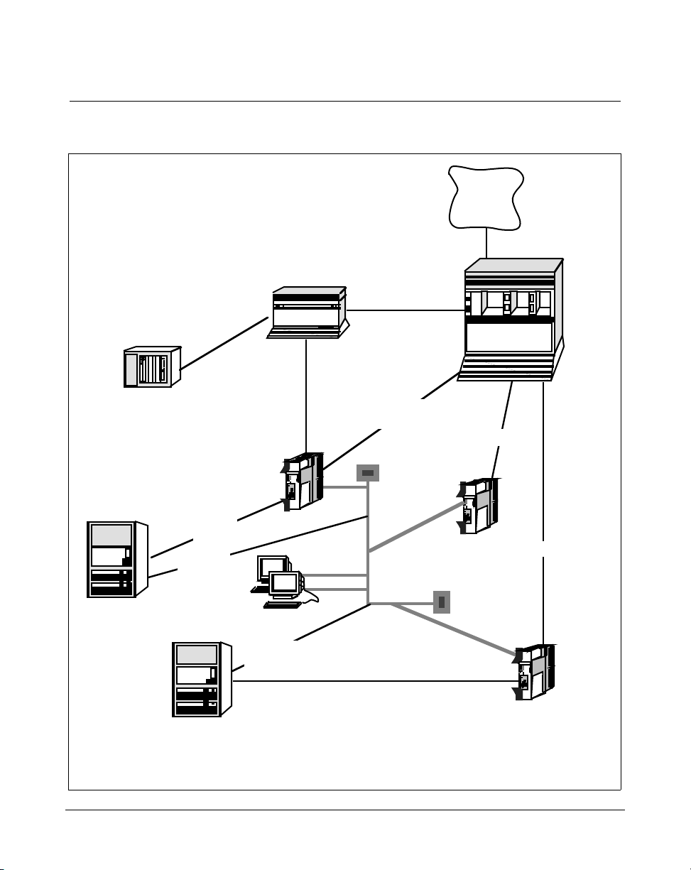
Figure 2 shows the hardware components for an IPE Module, while
Figure 3 shows the hardware components for the Application Module.
Meridian Link Release 5C/CCR Release 3C Installation and Upgrade Guide
Page 28
10 Chapter 2: Overview of Meridian Link
TP
TP
Figure 2
Meridian Link hardware connections (IPE Module)
Telephone
Network
Meridian 1
Universal
Equipment
Module (UEM)
Meridian IVR
AM
Host computer
Meridian Link
IPE Module (or AM)
Host Link
(X.25)
Host Link
(TCP/IP)
Remote system console
Host Link
(TCP/IP)
Host computer
Meridian Mail
Meridian Mail
Link (MML)
TP
Host Link (X.25)
Command and
Status Link (CSL)
Application Module
Link (AML)
Ethernet
(LAN)
Meridian Link/CCR
Co-residency
IPE Module (or AM)
AML
AML
Redundant
Meridian Link/CCR
Co-residency
IPE Module (or AM)
553-3202-210 Standard October 1998
Page 29
Chapter 2: Overview of Meridian Link 11
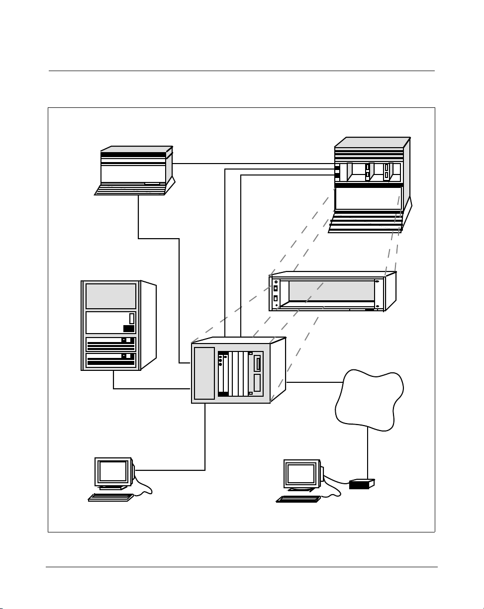
Figure 3
Meridian Link hardware connections (Application Module)
Meridian Mail
Command and
Status Link (CSL)
Meridian 1 Universal
Equipment Module (UEM)
Meridian Mail
Link (MML)
Host computer
Meridian Link
(X.25 or TCP/IP)
Application
Module Link
(AML)
Meridian Link
optional
Meridian 1
OA&M access
Application Equipment
Module (AEM)
to optional
modem
Telephone
network
Module
System console Remote
system console
Meridian Link Release 5C/CCR Release 3C Installation and Upgrade Guide
Modem
Page 30

12 Chapter 2: Overview of Meridian Link
Connecting these hardware components requires two (optionally three)
signaling links:
¥ Link 0 is an Application Module Link (AML), which connects the
Meridian 1 system to the IPE Module or the Application Module.
¥ Link 1 is a Host Link (or Meridian Link), which connects the host
computer to the IPE Module or the Application Module. This Host Link
can be implemented as a dedicated X.25 link supporting a single host
computer or as a TCP/IP Ethernet LAN link supporting as many as 16
Meridian Link applications.
Note 1: If both the Meridian Link (using TCP/IP) and CCR
applications are running, the Meridian Link third-party application can
support only up to 15 Meridian Link applications.
Note 2: Any mlusr administration sessions requiring association IDs
will reduce the number of association IDs available for Meridian Link
applications. For example, if your system has eight association IDs
registered to Meridian Link applications and then you register two
association IDs for mlusr administration, your system will have six
association IDs available (five, if CCR is running).
Note: If you have registered all 16 association IDs (15 if CCR is
running) to Meridian Link applications, two overflow association IDs
are available for mlusr administration only.
¥ Link 2 is (optionally) a Meridian Mail Link (MML), which connects a
Meridian Mail system to the IPE Module or the Application Module.
In addition, the IPE Module and the Application Module provide an
interface for a system console, which enables you to perform administration
and maintenance. A port that is designed to be connected to a modem
allows you to perform these activities from a remote location.
The key software required to make these hardware components and links
work together is the Meridian Link application, which resides in the IPE
Module or Application Module.
553-3202-210 Standard October 1998
Page 31

Meridian Link application
The Meridian Link application enables a host computer to control and
monitor telephone functions, such as making a call, answering a call,
tracking calls as they move through the Meridian 1 system, and conducting
Interactive Voice Response (IVR) sessions with a call.
To provide the required communication, Meridian Link passes messages
back and forth between a host computer and the Meridian 1 system, and
between a host computer and Meridian Mail system, through the Meridian
Link application in the IPE Module or the Application Module.
A customer application can use Meridian Link messages to
¥ monitor calls presented to, answered at, and released from phone sets,
including Automatic Call Distribution (ACD) agents
¥ set an agentÕs state (login, MSB, RDY)
¥ set CFWD (call forward all calls) for an associated set (AST)
¥ toggle a telephone message indicator (MWI)
¥ monitor the activity of an associated set
¥ make, answer, and release calls on behalf of an associated set
Chapter 2: Overview of Meridian Link 13
¥ transfer and set up conference calls on behalf of associated sets and
AST ACD agents
¥ control the routing of a call based on the number dialed (Dialed
Number Identification Service or DNIS) or the number from which the
call is placed (Automatic Number Identification or ANI, Calling Line
Identification or CLID), the time of day, the incoming trunk, and so on
¥ control a Host Enhanced Voice Processing (HEVP) session to play
voice prompts and collect Dual Tone Multi-Frequency (DTMF) touchtone digits to read the callerÕs response
Operating system overview
The IPE Module and the Application Module provide the base operating
system (BOS) software. BOS is release 3 version 7.1 of UNIX System V for
68000-family CPUs. For advanced users, the BOS tape contains online
operating-system information in the form of manual (MAN) pages.
Meridian Link Release 5C/CCR Release 3C Installation and Upgrade Guide
Page 32

14 Chapter 2: Overview of Meridian Link
New with Meridian Link Release 5C
The Meridian Link Release 5C introduces the following new features:
¥ redundant Meridian Link
¥ dual VAS ID
¥ expanded DNIS support
¥ SFN (login) message with agent ID
Redundant Meridian Link This feature implements a second Meridian
Link between the Meridian 1 and the host to increase the reliability of the
CTI interface. In normal operation, one of the Meridian Link modules is
active while the other is in warm standby mode. In the event of a failure (for
example, the AML goes down or the active Meridian Link crashes), a
switch-over to the redundant Meridian Link occurs automatically.
Dual VAS ID Meridian Mail (MMail) and Meridian Link communicate with
Meridian 1 through the Application Module Link (AML). In the ACD Data
Block, we associate the MMail ACD-DN with MMail through a VAS ID for
the corresponding AML. AML is defined per ACD DN basis. Currently,
only one VAS ID (for MMail) can be associated to an MMail ACD-DN.
Hence AML messages are communicated only to the MMail for any event
on MMail ports. The Dual VAS ID feature offers the facility to have MMail
and Meridian Link to be associated with an MMail ACD-DN so that AML
messages would flow to both MMail and Meridian Link.
Expanded DNIS support This feature allows an ACD agent to identify a
particular product the caller is interested in via the dialed number presented
to the agent. A third party application uses this DNIS number to display
product information on an agent's screen enabling the agent to answer the
call with correct responses. With Meridian Link 5C, up to 31 DNIS digits
are supported. X11 Release 24 is required to support greater than a sevendigit DNIS. Prior to Release 24, only seven digits were supported.
553-3202-210 Standard October 1998
Page 33

SFN (login) message with agent ID This feature sends an unsolicited
message to the host application when an AST/Acquired agent logs in by
manually pressing the MSB key on the ACD set or by invoking the ACD set
feature through the Set Feature Invocation (Login) message. The existing
SFN Login message has been enhanced to provide an optional four-digit
Agent ID at the time of logging, enabling the agent to log in at different
positions.
Link overview
Although Meridian Link effectively provides a single link between the host
computer and the Meridian 1 system, from an administrative and
maintenance standpoint there are actually three links.
Link 0 The link between the IPE Module or Application Module and
Meridian 1 is called link 0 or Application Module Link (AML).
Link 1 The link between the IPE Module or Application Module and the
host computer is called link 1, the Host Link, or the Meridian Link.
Link 2 The link between the IPE Module or Application Module and
Meridian Mail is called link 2 or the Meridian Mail Link (MML).
Chapter 2: Overview of Meridian Link 15
Note: X11 Release 24 is required to support this feature.
AML and the Host Link (or Meridian Link)
The AML (link 0) uses the LAPB protocol to transfer command and status
messages, primarily to perform call-processing functions. The Host Link or
Meridian Link (link 1) uses an X.25 switched virtual circuit or a TCP/IP
protocol to transfer application messages.
In data communication terms, the Meridian Link interface begins with the
physical (RS-232) layer, upon which the link (LAPB) and network (X.25 or
TCP/IP) layers are established. Messages are then sent across the link
between the host computer and Meridian 1 at the application layer level.
If the link uses an X.25 or TCP/IP connection, the host application
communicates with the Meridian 1 switch using Meridian Link formatted
messages.
Meridian Link Release 5C/CCR Release 3C Installation and Upgrade Guide
Page 34

16 Chapter 2: Overview of Meridian Link
Note: When setting up a redundant Meridian Link, two
communication paths must be set up to two separate Meridian Link
modules. This may involve two X.25 ports or two TCP/IP addresses.
Meridian Mail Link
The MML is an optional asynchronous link that connects the IPE Module or
Application Module to a Meridian Mail system running software version
MM8 (or later) with the Access Enable option. This link allows voice
processing messages to be used.
Diagnostic tools
For diagnosing link problems, you can use the loopback and continuity
commands to test link 0 and link 1. You can also use link traces, system
logs, console messages, and other tools to diagnose hardware, software, and
link problems. For more detailed information on diagnosing problems, refer
to the Application Module and Intelligent Peripheral Equipment Module
Diagnostic and Maintenance Guide (NTP 553-3211-510) and the
Application Module and Intelligent Peripheral Equipment Module
Advanced Maintenance Guide (NTP 553-3211-512).
If you are an advanced technical user of the IPE Module or Application
Module, you have access to the following diagnostic tools, which provide
extra maintenance capabilities:
¥ Remote maintenance access This enables a technician to dial into the
system from a remote site in order to perform troubleshooting
procedures.
¥ Standalone System Interactive Diagnostics (SSID) software This is
for testing many of the hardware components when the application
software is not running.
553-3202-210 Standard October 1998
Page 35

Chapter 2: Overview of Meridian Link 17
System console and maintenance console
You can use a customer-supplied console to enter OA&M commands to the
IPE Module or the Application Module. The console should be an
asynchronous ASCII terminal that is 100 percent compatible with ANSI and
DEC VT220. You can use an IBM-compatible personal computer running
Reflection 4+.
An NT1R03D cable connects the customer-supplied console to the IPE
Module. An NT7D61 External I/O cable or a customer-supplied 9-pin-to25-pin cable connects the customer-supplied console to the Application
Module. Refer to Chapter 9, ÒMeridian Link/CCR interface cablingÓ for
more information.
If you configure the optional conshare capability available to an IPE
Module or an Application Module, you can access the Meridian 1
input/output programs from the Meridian Link console.
Meridian Link administration and maintenance
As a Meridian Link administrator, you can use commands to do the
following:
¥ enable and disable the link between the host and the IPE Module or the
Application Module (link 1), the link between the IPE Module or the
Application Module and the Meridian 1 (link 0), and the link between
the IPE Module or the Application Module and Meridian Mail (link 2)
¥ configure link 0, link 1, and link 2
¥ display the status of a link or all links
¥ display protocol statistics for a link
¥ trace messages flowing on the links
¥ display messages flowing on the links on the system console
¥ filter particular messages
Meridian Link Release 5C/CCR Release 3C Installation and Upgrade Guide
Page 36

18 Chapter 2: Overview of Meridian Link
You can also use commands to do the following:
¥ back up and restore configuration and data files
¥ display how much disk space has been used up
¥ verify files
¥ delete files
¥ power down or reset the IPE Module or Application Module
Although the IPE Module and the Application Module arrive with the
software already installed, you can reinstall the software from tapes that are
supplied with the IPE Module or the Application Module (if it is necessary
to replace or reformat the hard disk).
Host support service requirements
The Meridian 1 system requires specific software to be installed in the
Meridian 1, and specific software to be installed in the IPE Module or
Application Module. Messages used by Meridian Link are divided into
related groups, called services in the IPE Module or Application Module.
The services required depend on the type of host computer. For more
specific information, refer to the ÒHostÓ section later in this chapter.
Meridian 1
This section provides overviews of the Meridian 1 hardware and software
required for Meridian Link.
Hardware overview
One of the following system types must be installed and operational:
¥ Meridian 1 system options 11, 11C, 21, 51, 51C, 61, 61C, 71, 81, or
81C (not all system options are supported in all markets)
¥ Meridian SL-1 systems (upgraded) capable of operating on Generic
X11 Release 16, or later, software
The Meridian 1 system must have particular cards installed:
¥ one of the following interface cards for the AML connection:
553-3202-210 Standard October 1998
Page 37

Chapter 2: Overview of Meridian Link 19
Ñ QPC513 Enhanced Serial Data Interface (ESDI) card (vintage G or
later)
Ñ NT6D80 Multi-purpose Serial Data Link (MSDL) card
Ñ (Option 11 only) NTAK02AB Serial Data Interface/D-Channel
Interface (SDI/DCH) card
Ñ If using a redundant Meridian Link, two AML connections are
required.
¥ a Serial Data Interface (SDI) card if conshare capability is desired
Note: Conshare capability, which gives you access to MeridianÊ1
input/output programs from the Meridian Link console, is
recommended to allow for more effective support for your system.
Option 11 systems support an SDI port on any of the following cards:
Ñ the CPU/CONF card (NTAK01AB)
Ñ the SDI/DCH card (NTAK02AB)
Ñ the TDS/DTR card (NTAK03AB)
¥ for optional voice-processing capability, a Meridian Mail system
¥ limited-distance modems for communications facilities if the IPE
Module or the Application Module is greater than 15 m (50 ft) from the
host computer
An Application Equipment Module (AEM), if present, must be installed in
one of the following configurations:
¥ a stand-alone AEM column or Meridian SL-1 style cabinet
¥ a module in a Meridian 1 column
Refer to Application Equipment Module Installation Guide
(NTP 553-3201-200) for AEM installation procedures.
The following table shows hardware supported for the Meridian Link and
CCR applications.
Meridian Link Release 5C/CCR Release 3C Installation and Upgrade Guide
Page 38

20 Chapter 2: Overview of Meridian Link
Table 1
Hardware supported for Meridian Link and CCR
Application MVME147 AM MVME167 AM IPE Module
Meridian Link 5C with X.25 Yes** Yes Yes
Meridian Link 5C with TCP/IP No Yes* Yes
Meridian Link 5C and CCR 3C No Yes* Yes
* This configuration is supported provided it is Ethernet accessible.
Upgrading the MVME147 AM with an MVME167 card is not equivalent to
an MVME167 AM therefore Meridian Link 5C using TCP/IP transport is
not supported.
** Refer to the Meridian Link/Customer Controlled Routing Engineering
Guide (NTP 553-3211-520) for details on the MVME147 CPU card.
553-3202-210 Standard October 1998
Page 39

Software overview
The Meridian 1 must be equipped with the following release of software:
¥ X11 Release 17 or later for Meridian 1 systems using Meridian Link
Release 4
¥ X11 Release 20 or later for all Option 11 systems (X11 Release 18 will
be supported in Europe)
¥ X11 Release 16.82G or later for Options 21Ð81 for international
markets
¥ X11 Release 19 or later for the Host Enhanced Routing, Host Enhanced
Voice Processing, and Unique Call ID features of Meridian Link
Release 4, and for Single Terminal Access (STA) support
¥ X11 Release 23 or later is required to support the Redundant Meridian
Link and Dual VAS ID features
¥ X11 Release 24 or later is required for the Expanded DNIS support and
Agent Login ID features
The following X11 software packages constitute Meridian Link:
¥ For Option 11:
Chapter 2: Overview of Meridian Link 21
Ñ Advanced Application Software (contains packages 153 and 209)
¥ For Options 21Ð81:
Ñ Application Module (package 209)
Prerequisites for Meridian Link operations are
¥ Meridian Mail Link (package 35)
¥ Command and Status Link (package 77)
These software options may be bundled in various marketing packages that
may vary by market and by X11 software release.
Following is a minimum software requirement compatibility matrix for the
Meridian Link/CCR application.
Meridian Link Release 5C/CCR Release 3C Installation and Upgrade Guide
Page 40

22 Chapter 2: Overview of Meridian Link
Table 2
X11 software compatibility matrix
Application Rls. 17 Rls. 18 Rls. 19 Rls. 20 Rls. 21 Rls. 22-24
Meridian Link 4B Yes Yes Yes Yes Yes Yes
Meridian Link 4B
and CCR 3B
Meridian Link 5 No No Yes Yes Yes Yes
Meridian Link 5
and CCR 3B
Meridian Link 5
Upissue and CCR 3B
Meridian Link 5C and
CCR 3C
Yes Yes Yes Yes Yes Yes
No No Yes Yes Yes Yes
No No Yes Yes Yes Yes
No No Yes Yes Yes Yes
Other software options may be required depending on specific application
needs. These may include options for ISDN and ACD, for example.
For information about software package prerequisites, refer to X11 Features
and Services (NTP 553-3001-305).
Meridian Link does not support pretranslation for outbound calls if the HVS
(Hospitality Voice Services), package 179, is installed.
553-3202-210 Standard October 1998
Page 41

Host
Chapter 2: Overview of Meridian Link 23
This section describes the services and software that Meridian Link requires
to support the connection to the host computer. Normally these services are
bundled in marketing packages that may vary by market.
Meridian Link service requirements
Meridian Link requires specific software services to be installed in the IPE
Module or Application Module to support the host connection. The services
required depend on the type of host computer.
X.25 and TCP/IP services are compatible with commonly available host
computers (including those from Hewlett Packard, IBM Corporation, and
Tandem Corporation). At least one of the following services is required:
Ñ Inbound Call Management (service 97) supports inbound call
applications such as telemarketing and customer service (includes
transfer and conference). This service does not support outbound
applications.
Ñ Outbound Call Management (service 98) supports outbound call
applications such as power or predictive dialing (includes transfer and
conference). This service does not support inbound applications.
Ñ Host Enhanced Routing (service 100) supports the RouteRequest and
RouteCall messages, giving the host application the ability to route
incoming calls.
Ñ Host Enhanced Voice Processing (service 101) supports voice-
processing capability for applications.
Service No. Description
95 Obsolete
96 Obsolete
97 Inbound Call Management
98 Outbound Call Management
100 Host Enhanced Routing
101 Host Enhanced Voice Processing
Meridian Link Release 5C/CCR Release 3C Installation and Upgrade Guide
Page 42

24 Chapter 2: Overview of Meridian Link
Host connection considerations
The link to the host computer should be installed and configured following
the host manufacturerÕs recommendations. The host may establish one of
the following, depending on the type of host computer:
¥ an X.25 Switched Virtual Circuit (SVC) connection over a serial
RS-232 (up to 19.2 kbps) physical interface
¥ TCP/IP connection over an Ethernet LAN
If the host computer is located more than 15 m (50 ft) from the IPE Module
or Application Module with an RS-232 connection, limited-distance
modems must be used at each end to carry the data signal (using standard
data communication techniques). You may select and install limiteddistance modems to connect the host computer and the IPE Module or
Application Module. Nortel neither supplies nor recommends a particular
make or model of modem for this purpose. If diagnostic activities indicate
that problems exist with the modems, Nortel support personnel will
recommend that the customer call in service representatives for the modem
equipment.
Note: When setting up a redundant Meridian Link, two host
connections are required, and two AML links must be configured on
the Meridian 1. Also, two communication paths (either two X.25 ports
or two TCP/IP addresses) must be set up to connect with two Meridian
Link modules.
Ethernet LAN-based host
To use an Ethernet LAN-based host computer, a local area network (LAN)
must be installed between an Ethernet LAN-based host computer and the
Meridian Link/CCR IPE Module or Application Module. Each IPE Module
or Application Module must have the Network Service Extension (NSE)
software running to provide TCP/IP service.
The Ethernet LAN-based host connection is compatible with IEEE802.3
Ethernet Standards and Ethernet II Standards using 10-based T, 10-based 2,
10-based 5, and fiber optics.
553-3202-210 Standard October 1998
Page 43

Chapter 2: Overview of Meridian Link 25
Ethernet support is automatically enabled during application installation. All
NSE files will be loaded to the hard disk for configuration by the customer
during installation. To configure the NSE, see Procedure 8 in Chapter 14,
ÒSoftware installation, upgrade, and update procedures.Ó
Note: If you do not intend to provide Ethernet LAN-based
communications on your system, you should disable the support during
application installation (you do this by entering the appropriate
keycode). By disabling this support, you increase the processing power
available to Meridian Link and CCR.
For Ethernet LAN support, Application Modules must contain
¥ an MVME167-02 SBC card
¥ an MVME712M transition card
¥ a generic I/O panel
¥ NT7D47DA and NT7D47EA cables
For more information about installing the NT7D47DA and NT7D47EA
cables, refer to Procedure 28: Installing the cables for Ethernet LAN support
in Chapter 17, ÒHardware upgrade.Ó
For more information about the MVME167-02 card, the MVME712M
transition card, and the generic I/O panel, refer to Chapter 4,
ÒMeridian Link/CCR hardware.Ó
If an IPE Module or an Application Module is removed from the network,
the remaining modules and PCs that used to have access must be informed
of the disconnection. How to remove the IPE Module or Application
Module entry from the accessing database depends on the TCP/IP software
used on the PC.
When you disconnect the IPE Module or Application Module from the
network, you must use the maint command stopNSE to disable the NSE
software, or error messages will appear on the system console. For more
information on the stopNSE command, refer to the Application Module and
Intelligent Peripheral Equipment Module Diagnostic and Maintenance
Guide (NTP 553-3211-510).
Meridian Link Release 5C/CCR Release 3C Installation and Upgrade Guide
Page 44

26 Chapter 2: Overview of Meridian Link
Meridian Mail software requirements
A Meridian Mail system can be connected to the IPE Module or Application
Module to provide voice-processing capability to an application based on
Meridian Link. The link between the IPE Module or Application Module
and the Meridian Mail system is called the Meridian Mail Link (MML).
The Meridian Mail system must be equipped with Release 8 (or later)
software with the Access Enable option, and Meridian 1 must be equipped
with X11 Release 19 (or later) software.
Operations, Administration, and Maintenance (OA&M)
The IPE Module and the Application Module also provide a basic
Operations, Administration, and Maintenance (OA&M) command interface,
which allows you to perform functions such as the following:
¥ access and configure applications (start or stop applications, configure
the application to start automatically and enter the application interface)
¥ power down the system safely
¥ schedule and perform system backup and restore operations
¥ run diagnostics
¥ change user passwords
¥ run traces on links
¥ access the Meridian 1 console, if console-sharing capability is
configured
¥ look at system information (system version, system logs)
553-3202-210 Standard October 1998
Page 45

Chapter 3: Overview of Customer Controlled Routing
Customer Controlled Routing (CCR) is a product that enables you to control
and route Automatic Call Distribution (ACD) calls entering your Meridian 1
system. For example, for an incoming ACD call, you can provide a specific
recorded announcement, music, or both, before assigning the call to an
agent.
Principal hardware components used by CCR are
¥ a Meridian 1 system
¥ an Application Module or Intelligent Peripheral Equipment (IPE)
Module (which contains the CCR application, service 99)
Connecting these hardware components is a signaling link called the
Application Module Link (AML), sometimes referred to as a Command and
Status Link (CSL).
In addition, the IPE Module or Application Module provides an interface
for a system console, which enables you to perform administration and
maintenance. A port that is designed to be connected to a modem allows
you to perform these activities from a remote location.
27
CCR also provides for as many as three terminals or printers on an IPE
Module (depending on the applications installed) or eight terminals or
printers on an Application Module. You can increase the number of
terminals by adding LAN-based PCs.
Figures 4 and 5 show how these hardware components are connected.
Meridian Link Release 5C/CCR Release 3C Installation and Upgrade Guide
Page 46

28 Chapter 3: Overview of Customer Controlled Routing
r
A
Figure 4
CCR hardware connections (IPE Module)
PC using
Printe
Reflection 4+
LAN
Printer
Terminal
Meridian 1
AML
Cable
NT1R03BA
IPE Module installed in a Meridian 1
Cable
NT1R03A
Maintenance
Console
553-3202-210 Standard October 1998
Page 47

Chapter 3: Overview of Customer Controlled Routing 29
Figure 5
CCR hardware connections (Application Module)
Remote
Diagnostics
PC using
Reflection 4+
Printer
Maintenance
Console
AML
LAN
Application Module installed in a Meridian 1
Meridian 1
PC using
Reflection 4+
The key software required to make these hardware components and links
work together is the CCR application, which resides in the IPE Module or
the Application Module.
Meridian Link Release 5C/CCR Release 3C Installation and Upgrade Guide
Page 48

30 Chapter 3: Overview of Customer Controlled Routing
CCR application
CCR works with the Automatic Call Distribution (ACD) feature on your
Meridian 1 to give you more control over the handling of incoming calls.
Each call coming through an ACD queue can be given individualized
handling and treatment. CCR provides specialized treatments for different
types of calls and, at the same time, pools your ACD resources to best
handle your call load.
CCR accomplishes this using a special kind of ACD Directory Number
(DN) called a Control DN (CDN), which is assigned to each incoming call.
Each CDN defined in Meridian 1 can have a unique series of call-handling
instructions applied to it. These instructions are contained in a script, which
is maintained using the CCR application.
The script determines how a call will be routed to the appropriate
destination and how that call is treated while waiting in an ACD queue.
Scripts can be as simple or as sophisticated as your application requires and
are not limited to a specific number of steps.
Using a script, you can, for example
¥ simultaneously queue a call to as many as eight ACD DNs, also
referred to as ACD queues
¥ simultaneously assign a call a different priority level for each queue
¥ change priority levels, depending on special conditions such as the age
of the call
¥ define recorded announcements, music, or both, for incoming calls
¥ determine how long a customer must wait before some action is taken
An example of CCR call handling
A customer service organization typically receives calls from a number of
different types of users. The organization may have different products that
they sell and support, and they may also have an elite client list to which
they provide special services.
These requirements can be handled using a single script that contains the
following types of instructions:
553-3202-210 Standard October 1998
Page 49

¥ For elite clients Any incoming call coming from telephone number
XXX or YYY goes into the ACD queue with a higher priority (using
the Calling Line Identification, or CLID, feature).
¥ Sales for all products Any incoming call to DN 1234 goes into the
ACD queue for the sales group.
¥ Support for product X Any incoming call to DN 2345 goes into the
ACD queue for the product X support group.
¥ Support for product Y Any incoming call to DN 3456 receives a
recorded announcement (RAN) regarding new product information
before going into the ACD queue for the product Y support group.
Key CCR concepts
This section describes terms used for CCR.
Script This is a collection of statements defining call routing and treatment.
CDN A Control DN is a special ACD DN, configured in Meridian 1, to
which no agents are assigned. You must create a script to control calls in the
CDN, otherwise the calls are put into the default mode. A script is
associated with a CDN, so all calls entering a CDN are handled by the same
script.
Chapter 3: Overview of Customer Controlled Routing 31
Association This is a mapping between a script and CDNs. The
Association Table tells the system which script controls the calls entering a
CDN.
Variable This is a user-defined name that represents a value or set of
values. Variables, such as Òafter_hoursÓ representing the value Ò17:00 to
06:00,Ó are defined in the Variable Table.
Profile All CCR application users have a profile that defines their level of
access to the system and the language they will use (French or English).
Operating system
The IPE Module and Application Module provide base operating system
(BOS) software. BOS is release 3 version 7.1 of UNIX System V for 68000family CPUs. For advanced users, BOS contains online operating system
information in the form of manual (MAN) pages.
Meridian Link Release 5C/CCR Release 3C Installation and Upgrade Guide
Page 50

32 Chapter 3: Overview of Customer Controlled Routing
New with CCR Release 3C
CCR Release 3C introduces the following new features:
¥ expanded DNIS support
¥ support for 8 "Queue to" commands
Expanded DNIS support CCR can route and treat calls based on the DNIS.
With CCR Release 5C, the DNIS digits supported have been expanded from
seven digits to a maximum of 31 digits. X11 Release 24 is required to
support more than seven digits.
Support for 8 "Queue to" commands" This feature allows a call waiting
for an available agent to be queued to up to eight different queues
simultaneously. A call can be queued at each of the eight ACD DNs at the
same priority or at different priorities, offering better customer service due
to faster response times.
Application Module Link
The Application Module Link (AML) (link 0) uses the LAPB protocol to
transfer command and status messages, primarily to perform call processing
functions.
Diagnostic tools
Advanced technical users of the IPE Module or Application Module have
access to the following diagnostic tools, which provide extra maintenance
capabilities:
¥ Remote maintenance access This enables a technician to dial in to the
system from a remote site to perform troubleshooting procedures.
¥ Standalone System Interactive Diagnostics (SSID) software This is
used for testing hardware components when CCR is not running.
System console and maintenance console
You can use a customer-supplied console to enter OA&M commands to the
IPE Module or Application Module. The console should be an
asynchronous ASCII terminal that is 100 percent compatible with ANSI and
DEC VT220. You can use an IBM-compatible personal computer running
Reflection 4+.
553-3202-210 Standard October 1998
Page 51

Chapter 3: Overview of Customer Controlled Routing 33
An NT1R03D cable connects the customer-supplied console to the IPE
Module. An NT7D61 External I/O cable or a customer-supplied 9-pin-to25-pin cable connects the customer-supplied console to the Application
Module. Refer to Chapter 9, ÒMeridian Link/CCR interface cablingÓ for
more information.
If you configure the optional conshare capability available to the IPE
Module or Application Module, you can access the Meridian 1 input/output
programs from the CCR console.
CCR administration and maintenance
CCR provides an interface for a system console user and as many as eight
other terminal users at one time. All users have access to basic OA&M
commands and to the CCR application itself. But only one user can create,
edit, install, associate, and access CCR data at a time.
CCR employs a full-screen, menu-driven interface that allows you to
¥ set up and maintain profiles for CCR application users
¥ create, modify, and verify scripts
¥ set up and maintain a list of variables that are used within scripts to
make script maintenance easier
¥ set up and maintain associations between scripts and the CDNs defined
on Meridian 1
Consoles/printers
In addition to the system console, CCR can support as many as eight
terminals or printers. The additional terminals allow as many as eight
application users to have access to the CCR user interface at the same time,
although only one user can change CCR data at a time.
Note: The IPE Module can support only a maximum of three
terminals or printers; only two if CCR is co-resident with Meridian
Link. However, you can increase the number of terminals by adding
LAN-based PCs.
Meridian Link Release 5C/CCR Release 3C Installation and Upgrade Guide
Page 52

34 Chapter 3: Overview of Customer Controlled Routing
Meridian 1
This section provides overviews of the Meridian 1 hardware and software
required for CCR.
Hardware overview
One of the following system types must be installed and operational:
¥ Meridian 1 system options 21, 51, 61, 71, or 81 (not all system options
are supported in all markets)
¥ Meridian 1 system option 11
¥ Meridian SL-1 systems (upgraded) capable of operating on generic X11
Release 17, or later, software
The Meridian 1 system must be up and running, and have the following
hardware installed:
¥ one of the following interface cards:
Ñ QPC513 Enhanced Serial Data Interface (ESDI) card (vintage G or
later)
Ñ NT6D80 Multi-purpose Serial Data Link (MSDL) card
Ñ (Option 11 only) NTAK02AB Serial Data Interface/D-Channel
Interface (SDI/DCH) card
¥ a Serial Data Interface (SDI) card if conshare capability is desired
Note: Conshare capability, which gives you access to MeridianÊ1
input/output programs from the IPE Module or Application Module
console, is highly recommended to allow for more effective support for
your system. If you want to access Meridian 1 and up to three other
applications, the Single Terminal Access (STA) feature is available
with X11 release 19 and greater. For more information on STA, refer to
Chapter 19, ÒSingle Terminal Access.Ó
553-3202-210 Standard October 1998
Page 53

Chapter 3: Overview of Customer Controlled Routing 35
Option 11 systems support an SDI port on any of the following cards:
Ñ the CPU/CONF card (NTAK01AB)
Ñ the SDI/DCH card (NTAK02AB)
Ñ the TDS/DTR card (NTAK03AB)
¥ limited-distance modems for communications facilities if the IPE
Module or Application Module is greater than 15 m (50 ft) from the
Meridian 1 or peripheral devices, such as terminals and printers
An Application Equipment Module (AEM), if present, must be installed in
one of the following configurations:
¥ as a stand-alone AEM column (the configuration used with Meridian
SL-1 style cabinets)
¥ as a module in a Meridian 1 column
Refer to Application Equipment Module Installation Guide
(NTP 553-3201-200) for AEM installation procedures.
The following table shows hardware supported for the Meridian Link and
CCR applications.
Table 3
Hardware supported for Meridian Link and CCR
Application MVME147 AM MVME167 AM IPE Module
CCR 3C No Yes Yes
Meridian Link 5C and CCR 3C No Yes* Yes
* This configuration is supported provided it is Ethernet accessible.
Upgrading the MVME147 AM with an MVME167 card is not equivalent to
an MVME167 AM therefore Meridian Link 5C using TCP/IP transport is
not supported.
Meridian Link Release 5C/CCR Release 3C Installation and Upgrade Guide
Page 54

36 Chapter 3: Overview of Customer Controlled Routing
Software overview
The Meridian 1 must be equipped with one of the following software
releases:
¥ Customer Controlled Routing: X11 Release 17 or later (Release 20 for
all Option 11 systems) or X81
¥ Customer Controlled Routing with access to Interactive Voice
Response (IVR) applications: X11 Release 18 (or later)
Following is a minimum software requirement compatibility matrix for the
Meridian Link/CCR application.
Table 4
X11 software compatibility matrix
Application Rls. 17 Rls. 18 Rls. 19 Rls. 20 Rls. 21 Rls. 22-24
Meridian Link 4B
and CCR 3B
CCR 3B Yes Yes Yes Yes Yes Yes
Meridian Link 5
and CCR 3B
Meridian Link 5
Upissue and CCR 3B
Meridian Link 5C and
CCR 3C
Yes Yes Yes Yes Yes Yes
No No Yes Yes Yes Yes
No No Yes Yes Yes Yes
No No Yes Yes Yes Yes
The following software packages (and their prerequisites) are required for
Customer Controlled Routing:
¥ Basic ACD (packages 40, 41, and 45)
¥ Command and Status Link (CSL) (package 77)
¥ Enhanced ACD Routing (package 214)
¥ Customer Controlled Routing (package 215)
553-3202-210 Standard October 1998
Page 55

Chapter 3: Overview of Customer Controlled Routing 37
¥ Interactive Voice Response (package 218) if the Hold In Queue for IVR
feature is to be used
¥ Call ID (package 247) (requires X11 Release 19 or later)
The following software packages (and their prerequisites) are optional for
Customer Controlled Routing:
¥ Dialed Number Identification Service (package 98)
¥ Automatic Call Distribution Package C (package 42)
¥ ACD Load Management (package 43)
¥ Automatic Call Distribution Package D (package 50)
¥ ACD Package D Auxiliary Link Processor (package 51)
¥ Integrated Services Digital Network Signaling (package 145)
¥ ISDN Primary Rate Access (package 146)
¥ ISDN Signaling Link (package 147)
¥ Multi-use Serial Data Link (package 222)
For information about software package prerequisites, refer to X11 Features
and Services (NTP 553-3001-305).
CCR may take advantage of many other software packages if they are
installed and configured.
Single Terminal Access (STA)
Single Terminal Access allows a single terminal (an STA terminal) to be
used as a maintenance terminal for the Meridian 1 system and for any
subsystem connected to it (including an IPE Module or an Application
Module) to perform all OA&M functions. For more information, refer to
Chapter 19, ÒSingle Terminal Access.Ó
The STA feature is supported on
¥ an IPE Module connected to a Meridian 1 Options 21Ð81 system
¥ an Application Module with an MVME167 card
Meridian Link Release 5C/CCR Release 3C Installation and Upgrade Guide
Page 56

38 Chapter 3: Overview of Customer Controlled Routing
553-3202-210 Standard October 1998
Page 57

Chapter 4: Meridian Link/CCR hardware
Meridian Link and CCR hardware consists of either an IPE Module or an
Application Module. This chapter describes both of these modules.
Note: If you require a redundant Meridian Link, an additional
Meridian Link Module (either an IPE Module or an Application
Module) must be installed.
Both the IPE Module and the Application Module use a base operating
system (BOS), which supports Meridian Link and CCR. BOS is release 3
version 7.1 of UNIX System V for 68000-family CPUs. For advanced users
who need more information, BOS provides operating system information in
the form of online manual (MAN) pages.
IPE Module
The IPE Module can be installed in a MeridianÊ1 Option 11 main cabinet or
expansion cabinet, or in a Meridian 1 Options 21Ð81 IPE shelf.
In a Meridian 1 Option 11 system, the IPE Module occupies three
consecutive slots in the main cabinet (Figure 6) or expansion cabinet
(Figure 7). Those three slots must not include slot 1 (reserved for the
SDI/TDS [NTAK03AA] card) or slots 10Ð12 in the main cabinet (reserved
for Meridian Mail).
39
Power for the IPE Module comes from the cabinetÕs IPE backplane and
consists of +5 V and Ð48 V.
Meridian Link Release 5C/CCR Release 3C Installation and Upgrade Guide
Page 58

40 Chapter 4: Meridian Link/CCR hardware
Figure 6 illustrates the IPE Module occupying slots 5Ð7 of the Option 11
main cabinet. Figure 7 illustrates the IPE Module occupying slots 14Ð16 of
the expansion cabinet.
Figure 6
Option 11 main cabinet
Meridian 1
Power
supply
AC/DC Pwr
Meridian Link
SCSI
0123456789
Pwr
Meridian Mail
Connector
panel
553-3202-210 Standard October 1998
Page 59

Figure 7
Option 11 expansion cabinet
Chapter 4: Meridian Link/CCR hardware 41
Meridian 1
Power
supply
AC/DC Pwr
Meridian Link
SCSI
11 12 13 14 15 16 17 18 19 20
Connector
panel
Meridian Link Release 5C/CCR Release 3C Installation and Upgrade Guide
Page 60

42 Chapter 4: Meridian Link/CCR hardware
Connector panel and I/O connectors (Option 11)
Underneath each cabinet of the Option 11 is a connector panel with ten
numbered connector ports. Each connector port connects to the
corresponding numbered slot directly above it, inside the cabinet. Figure 8
shows the connector panel for the main cabinet, and Figure 9 shows the
connector panel for the expansion cabinet.
The I/O connectors for the IPE Module installed in an Option 11 system are
standard, shielded, 50-pin tip-ring-type connector ports on the connector
panel, which is located under the cabinet containing the module. The
connector ports used depend on the slots occupied by the IPE Module.
Tables 5 and 6 show the connector ports used for each possible location of
the IPE Module. Figure 6 shows the IPE Module installed in slots 5, 6, and
7 of an Option 11 main cabinet. Table 5 shows that the cables are connected
to connector ports J5 and J7.
Figure 8
Option 11 connector panel (main cabinet)
012345678 9
Table 5
Option 11 IPE Module connectors used (main cabinet)
Slots occupied by IPE Module Connector ports used
2, 3, 4 J2 and J4
3, 4, 5 J3 and J5
4, 5, 6 J4 and J6
5, 6, 7 J5 and J7
6, 7, 8 J6 and J8
7, 8, 9 J7 and J9
553-3202-210 Standard October 1998
¥
Page 61

Figure 9
Option 11 connector panel (expansion cabinet)
11 12 13 14 15 16 17 18 19 20
Table 6
Option 11 IPE Module connectors used (expansion cabinet)
Slots occupied by IPE Module Connector ports used
11, 12, 13 J11 and J13
12, 13, 14 J12 and J14
13, 14, 15 J13 and J15
14, 15, 16 J14 and J16
Chapter 4: Meridian Link/CCR hardware 43
¥
15, 16, 17 J15 and J17
16, 17, 18 J16 and J18
17, 18, 19 J17 and J19
18, 19, 20 J18 and J20
Meridian Link Release 5C/CCR Release 3C Installation and Upgrade Guide
Page 62

44 Chapter 4: Meridian Link/CCR hardware
IPE Module Options 21Ð81
In a Meridian 1 Options 21Ð81 system, the IPE Module occupies four
consecutive slots on an IPE shelf (Figure 10). Power for the IPE Module
comes from the shelfÕs IPE backplane and consists of +5 V and Ð48 V.
Figure 10
Options 21Ð81 cabinet
!
--
--
--
--
---
---
--
--
--
--
---
---
--
--
----
----
---
---
--
--
TP
!
553-3202-210 Standard October 1998
Page 63

Connector panel and I/O connectors (Options 21Ð81)
The I/O connectors for the IPE Module installed in an Options 21Ð81 IPE
shelf are standard, shielded, 50-pin tip-ring-type connectors on one of the
I/O panels in the rear of the IPE shelf containing the module. Each panel has
ten connector ports. The I/O panel and connector ports used depend on the
slots occupied by the IPE Module. Figure 11 shows the connector ports used
for an IPE Module installed in slots 0Ð3 of an NT8D37 shelf. This figure is
illustrative only; for specific information about the relationship between
slots and connector ports, refer to Chapter 9, ÒMeridian Link/CCR interface
cabling.Ó
Note: Older CE/PE or IPE shelves (vintages AA and DC) do not have
fully cabled backplanes. They have one and a half cards per cable and
therefore you must reroute backplane cables inside the CE/PE or IPE
shelves before installing the IPE Module. For more information, refer
to the section on ÒBackplane cable rerouting for Options 21Ð81 CE/PE
and IPE backplanesÓ in Chapter 9, ÒMeridian Link/CCR interface
cabling.Ó
Figure 11
Options 21Ð81 IPE Module connectors (rear view)
Chapter 4: Meridian Link/CCR hardware 45
50-Pin connector
ABLK
SRNM
UT
IPE backplane
Left I/O panel Right I/O panel
Meridian Link Release 5C/CCR Release 3C Installation and Upgrade Guide
FEDC
HG
NT1R03BA
NT1R03AA
Ethernet
Page 64

46 Chapter 4: Meridian Link/CCR hardware
IPE Module components
The IPE Module (Figure 12) contains an SMM167 single board computer
(SBC) card, a 240-Mbyte disk drive, a 600-Mbyte tape drive, and a CPU
adapter card. Only the IPE Module as a whole is field-replaceable.
SMM167 single board computer (SBC) card
This card, one of the Motorola MVME167 family, consists of the following:
¥ MC68040 microprocessor operating at 25 MHz
¥ 16 Mbytes of dynamic random access memory (DRAM)
¥ MC68882 floating point coprocessor
¥ shared dynamic random access memory (DRAM) with parity
¥ time-of-day clock and calendar with battery backup
¥ 128 kbytes of static random access memory (SRAM)
The SBC card provides the following interfaces:
¥ Small Computer Systems Interface (SCSI) bus interface with direct
memory access (DMA) channel to control the disk/tape unit
¥ eight serial I/O ports with EIA-232-D buffers
¥ Ethernet transceiver interface
The SMM167 card is not field-replaceable.
The distance between the IPE Module and the terminals must be 15 m
(50 ft) or less due to the restriction of the RS-232 connections. Any
distances over 30 m (100 ft) require a limited-distance modem. See
Chapter 11, ÒPeripheral device cabling interfaceÓ later in this guide.
IPE Module faceplate
The IPE Module faceplate contains a SCSI connector, four light-emitting
diodes (LEDs), and three switches, as illustrated in Figure 12.
The SCSI connector must contain a SCSI terminator.
553-3202-210 Standard October 1998
Page 65

Chapter 4: Meridian Link/CCR hardware 47
The LEDs show the following conditions:
¥ PWR indicator This green LED is lit when power is turned on.
¥ Run indicator This yellow LED is lit almost continuously when an
application is running, but flickers every few seconds.
¥ SCSI indicator This yellow LED is lit almost continuously when in
use. The intensity varies according to the amount of data movement.
¥ Fail indicator This red LED is lit continuously when a hardware
failure occurs on the SBC card. It is normal for this indicator to flash
while diagnostics are being run (after power-on or during rebooting).
The switches perform the following functions:
¥ Power pushbutton This pushbutton turns power on and off the IPE
Module.
¥ ABORT button This button, when pressed, stops program execution
and returns control to the debugger. Do not press this button. If you
accidentally press it, all software operations will stop and you will be in
the firmware debugger. In this case, press the red RESET button
immediately to reboot the system. Software diagnostics during system
boot will attempt to repair possible file system damage caused by the
non-standard shutdown.
¥ RESET button This button invokes a cold restart. The system performs
a self test and then reboots. Do not press the button while an
application is running. Exit the application and prepare the system for
powering down before pressing the RESET button. If the SBC card is
the system controller, this button also generates a VME bus system
reset. The software powerdown procedure is provided in
Chapter 14, ÒSoftware installation, upgrade, and update procedures.Ó
CAUTION
Risk of data loss
!
Meridian Link Release 5C/CCR Release 3C Installation and Upgrade Guide
Do not press both the ABORT and RESET buttons at
the same timeÑyou risk losing device configuration
information.
Page 66

48 Chapter 4: Meridian Link/CCR hardware
Figure 12
IPE Module
Hard disk
External
SCSI connector
Tape drive
SCSI
!
PWR
RUN
SCSI
ABORT
RESET
FAIL
TP
!
Fits to the IPE
backplane for
power and I/O
CPU adapter
card
SMM167 CPU board
553-3202-210 Standard October 1998
Page 67

Table 7
Tape usage
Chapter 4: Meridian Link/CCR hardware 49
Tape drive (IPE Module)
The tape drive is a 600-Mbyte cassette tape drive, and cannot be replaced in
the field.
The following tapes are supplied with the IPE Module:
¥ a 155-Mbyte tape that provides the operating system for the IPE
Module
¥ a 155-Mbyte tape that provides the application software
¥ at least one blank tape for backups
Note: As shown in Table 7, the IPE Module cannot write to a
155-Mbyte tape, so you should only use a 600-Mbyte tape for backup.
(You cannot see through the sprocket holes of a 600-Mbyte tape.)
Module 600-Mbyte tape 155-Mbyte tape
IPE Module Read and write operations
(backup and program load)
Application Module with
155-Mbyte tape drive
(NT7D62)
Not compatible Read and write operations
Disk drive (IPE Module)
The disk drive is a 240-Mbyte drive, and cannot be replaced in the field.
Meridian Link Release 5C/CCR Release 3C Installation and Upgrade Guide
Read operation only
(program load only)
(backup and program load)
Page 68

50 Chapter 4: Meridian Link/CCR hardware
Application Module
An Application Module (AM) is a Versa Module Eurocard (VME) platform
that is packaged with the Application Equipment Module (AEM) of a
Meridian 1. The AEM is a modified Universal Equipment Module (UEM),
and can house two separate Application Modules.
The Application Module consists of a VME bus backplane, a single board
computer (SBC) card, one or more I/O cards and corresponding transition
cards, a hard disk and streamer cassette tape unit, and a power supply. The
Application Module chassis measures approximately 35.5 cm (14 in.) high,
32 cm (12-3/4 in.) wide and 32 cm (12-1/2 in.) deep.
An Application Module can co-reside with another Application Module in a
single Application Equipment Module.
If your Application Module contains Meridian Link but not CCR, it is
referred to as a Meridian Link Module and may have one of the five
configurations shown in Table 8. Table 8 shows the upgrade path for each
configuration. Notice that the second and fourth configurations are the first
and third configurations upgraded to an MVME167 card.
If your Application Module contains CCR but not Meridian Link, it is
referred to as a CCR Module and may have one of the five configurations
shown in Table 9. Table 9 shows the upgrade path for each configuration.
Notice that the second and fourth configurations are the first and third
configurations upgraded to an MVME167 card.
Your current module may have other hardware that varies from other
modules (for example, I/O panels, tapes, and disk drives), but these are not
important for determining upgrade paths.
The Application Module allows PC-based Meridian Link and CCR
maintenance consoles, CCR scripting consoles, and LAN-based host
computers to be connected to the Application Module through Ethernet.
553-3202-210 Standard October 1998
Page 69

Table 8
Hardware upgrade paths for Meridian Link Modules
Chapter 4: Meridian Link/CCR hardware 51
Meridian Link Module
configuration
MVME147 card
MVME712AM card
No NT6D51AA card
Internal modem
AC or DC power
MVME167 card
(Upgrade from above)
MVME712AM card
No NT6D51AA card
Internal modem
AC or DC power
MVME147 card
MVME712A card
No NT6D51AA card
No internal modem
DC power
MVME167 card
(Upgrade from above)
MVME712A card
No NT6D51AA card
No internal modem
DC power
Upgrade path to
Release 5C
None required.
Possible upgrade to
MVME167 card for
increased performance
(see below).
None required. No No
None required.
Possible upgrade to
MVME167 card for
increased performance
(see below).
None required. No No
Supports
co-residency?
No No
No No
Supports
Ethernet LAN?
MVME167 card
MVME712M card
NT6D51AA card
No internal modem
AC or DC power
None required. Yes.
Requires an
MVME332 card.
Meridian Link Release 5C/CCR Release 3C Installation and Upgrade Guide
Yes.
Requires
NT7D47DA
internal cable and
NT7D47EA drop
cable.
Page 70

52 Chapter 4: Meridian Link/CCR hardware
Table 9
Hardware upgrade paths for CCR Modules
CCR Module
configuration
MVME147 card
MVME712AM card
MVME332 card
NT6D51AA card
Internal modem
AC or DC power
MVME167 card
(Upgrade from above)
MVME712AM card
MVME332 card
NT6D51AA card
Internal modem
AC or DC power
MVME147 card
MVME712A card
MVME332 card
NT6D51AA card
No internal modem
DC power
MVME167 card
(Upgrade from above)
MVME712A card
No MVME332 card
No NT6D51AA card
No internal modem
DC power
Upgrade path to
Release 3C
None required.
Possible upgrade to
MVME167 card for
increased performance
(see below).
None required. Yes No
None required.
Possible upgrade to
MVME167 card for
increased performance
(see below).
None required. Yes No
Supports
co-residency?
Yes.
Requires an
MVME167 card
(see below).
Yes.
Requires an
MVME167 card
(see below).
No
No
Supports
Ethernet LAN?
MVME167 card
MVME712M card
MVME332 card
NT6D51AA card
No internal modem
AC or DC power
553-3202-210 Standard October 1998
None required. Yes. Yes.
Requires
NT7D47DA
internal cable and
NT7D47EA drop
cable.
Page 71

AEM power
Figure 13
AEMÑfront view
Module Power
Distribution Unit
(MPDU)
Breaker for
left-side module
Chapter 4: Meridian Link/CCR hardware 53
The AEM has an NT7D54AA (for AC power) or NT7D54AB (for DC
power) module power distribution unit (MPDU) on the left side (as you face
the AEM). The top circuit breaker in the MPDU controls power to the leftside Application Module (closest to the MPDU). The bottom breaker
controls power to the Application Module on the right side of the AEM.
Figure 13 illustrates an AEM viewed from the front.
Note: Only the NT7D54AB (DC power) AEM is available in Europe.
Application
Module
(left side)
Application
Module
(right side)
Breaker for
right-side module
Note: Either side of the AEM could house the Application Module
running Meridian Link and/or CCR. The other Application Module
could support another application.
Meridian Link Release 5C/CCR Release 3C Installation and Upgrade Guide
Page 72

54 Chapter 4: Meridian Link/CCR hardware
CAUTION
Risk of hardware damage
!
If you want to remove a card from an Application
Module, you must perform the required software and
hardware power-down processes. Hardware can be
damaged if a component is reseated on the VME bus
while the power is on, and the operating system can be
corrupted if the power switch is turned off before the
application performs a shutdown.
Application Module components
The Application Module chassis assembly houses the following basic
components (order codes for field-replaceable components are listed in
Chapter 20, ÒOrderingÓ at the end of this guide):
¥ an MVME147SA-1 or an MVME167-03 single board computer (SBC)
card
¥ an MVME333-102 X.25 Communication Controller (XCC) card
¥ an MVME332XTS transition card to support co-residency (present only
if CCR is installed)
¥ an MVME712M, MVME712A or MVME712AM transition card
¥ an MVME705B transition card
¥ an NT6D51AA transition card (required only if an MVME332XTS
card is present)
¥ a P2 adapter board
¥ a slide-in AC or DC power supply
¥ a slide-in disk-tape unit, which could be any of the following:
Ñ NT7D62AA: a 104-Mbyte hard disk drive and a 155-Mbyte tape
drive
Ñ NT7D62AB: a 172-Mbyte or a 180-Mbyte hard disk drive and a
155-Mbyte tape drive
553-3202-210 Standard October 1998
Page 73

Chapter 4: Meridian Link/CCR hardware 55
Ñ NT7D62AC: a 240-Mbyte hard disk drive and a 155-Mbyte tape
drive
¥ a six-slot VME bus backplane
¥ a power sense card
¥ a SCSI bus interface with direct memory access (DMA)
¥ an input/output (I/O) subpanel, a universal I/O panel, or a generic I/O
panel
CAUTION
Risk of system interruption
!
As shown in Figure 14, slots in the front of the Application Module house
the power supply, circuit cards, and the disk/tape unit as follows:
¥ the first card slot houses an MVME147 or MVME167 SBC card
It is recommended that suitable battery backup or
uninterruptible power supply (UPS) be installed so that
applications running on the Application Equipment
Module are not affected by commercial power outages.
¥ the second slot houses the MVME333-2 XCC card
¥ the third slot houses the MVME332XT or MVME332XTS card (for
CCR/Co-resident Module)
¥ the remaining slots are covered by blank faceplates to channel air flow
and thus maintain adequate cooling
CAUTION
Risk of hardware damage
!
Meridian Link Release 5C/CCR Release 3C Installation and Upgrade Guide
Do not operate the Application Module if the blank
faceplates have been removed; overheating may cause
equipment damage.
Page 74

56 Chapter 4: Meridian Link/CCR hardware
Figure 14
Application ModuleÑfront view
CCR/Co-resident Module (left side)
M
M
M
V
V
V
M
M
M
E
E
E
1
3
3
4
3
3
7
3
2
or
-
X
1
2
T
6
S
7
Power
supply
Disk/tape unit: topÑtape drive
bottomÑhard disk drive
Meridian Link Module (right side)
M
M
V
V
M
M
E
E
3
1
3
4
3
7
-
or
2
1
6
7
553-3202-210 Standard October 1998
Page 75

Figure 15
Application ModuleÑrear view
Chapter 4: Meridian Link/CCR hardware 57
Meridian Link Module
M
M
V
V
M
M
E
E
7
7
1
0
2
5
M
B
or
A
or
AM
J8
J9
CCR/Co-resident Module
M
M
N
V
V
T
M
M
6
E
E
D
7
7
5
0
1
1
5
2
A
B
M
A
or
A
or
AM
Transition cards
Part of chassis
(cannot be ordered)
Power sense card
As shown in Figure 15, slots at the rear of the Application Module house the
following cards:
¥ MVME712M (double-width), MVME712A, or MVME712AM
transition card
¥ MVME705B transition card
¥ NT6D51AA transition card (for CCR/Co-resident Module)
The power sense card and the adapter board are mounted in the rear of the
Application Module, either on the I/O subpanel, which is installed in the
AEM I/O panel in older installations, or on a central bracket at the bottom
of the AEM.
Meridian Link Release 5C/CCR Release 3C Installation and Upgrade Guide
Page 76

58 Chapter 4: Meridian Link/CCR hardware
Single board computer card (Application Module)
The first VME card slot (left-hand slot) of the Application Module is
occupied by the single board computer (SBC) card. One of two cards may
be installed, either the MVME147 or the MVME167 card.
MVME147SA-1
The MVME147 card consists of the following:
¥ MC68030 microprocessor
¥ 8 Mbytes of random access memory (RAM)
¥ MC68882 floating point coprocessor
¥ shared dynamic random access memory (DRAM) with parity
¥ time-of-day clock and calendar with battery backup
¥ 2 kbytes of static random access memory (SRAM)
¥ four read-only memory (ROM) sockets
¥ two 16-bit tick timers for periodic interrupts
¥ watchdog timer
The SBC card provides the following interfaces:
¥ SCSI bus interface with DMA channel to control the disk/tape unit
¥ four serial I/O ports with RS-232 interface
¥ Ethernet transceiver interface
The SBC card also provides the following functions:
¥ VME bus interrupter
¥ VME bus system controller functions
¥ VME bus master interface
¥ VME bus requester
553-3202-210 Standard October 1998
Page 77

Chapter 4: Meridian Link/CCR hardware 59
There are four light-emitting diodes (LEDs) and two switches on the
faceplate of the SBC card, as illustrated in Figure 16.
The LEDs show the following conditions:
¥ Fail indicator This red LED is lit continuously when a hardware or
software failure occurs on the SBC. It is normal for this indicator to
flash while diagnostics are being run (after power-on or during
rebooting).
¥ Status indicator This yellow LED is lit when the MC68030 Status
signal goes low. When steadily lit, the LED indicates that the processor
has stopped. When applications are running, the LED is lit almost
continuously but flickers every few seconds.
¥ Run indicator This green LED is lit when the microprocessor executes
a bus cycle. When applications are running, the LED is lit almost
continuously but flickers every few seconds.
¥ SCON indicator This green LED is always steadily lit to indicate that
the SBC card is the VME bus system controller.
The switches perform the following functions:
¥ ABORT switch This switch, when pressed, stops program execution
and returns control to the debugger. Do not press this switch. If you
accidentally press it, all software operations will stop and you will be in
the firmware debugger. In this case, press the red RESET switch
immediately to reboot the system. Software diagnostics during system
boot will attempt to repair possible file system damage caused by the
non-standard shutdown.
¥ RESET switch This switch invokes a cold restart. The system
performs a self test and then reboots. Do not press the switch while
applications are running. Exit all applications and prepare the system
for powering down before pressing the RESET switch. If the SBC card
is the system controller, this switch also generates a VME bus system
reset. The software power-down procedure is provided later in this
guide.
Meridian Link Release 5C/CCR Release 3C Installation and Upgrade Guide
Page 78

60 Chapter 4: Meridian Link/CCR hardware
CAUTION
Risk of data loss
!
The MVME712 transition card makes all serial I/O connections for the SBC
card. The SBC card communicates with the transition card through the
P2/J2 connector and the P2 adapter board. The SBC card connects to the
VME bus through the P1/J1 connector for address and data signals.
Do not press both the ABORT and the RESET switches at
the same timeÑyou risk losing device configuration
information.
553-3202-210 Standard October 1998
Page 79

Chapter 4: Meridian Link/CCR hardware 61
Figure 16
MVME147SA-1 single board computer (SBC) card (Application Module)
MVME
147SA-1
FAIL
STATUS
RUN
SCON
RMT RST
ABORT
RESET
Meridian Link Release 5C/CCR Release 3C Installation and Upgrade Guide
Page 80

62 Chapter 4: Meridian Link/CCR hardware
MVME167-03
This card, one of the Motorola MVME167 family, may be installed in place
of the MVME147 card in new modules running Meridian Link and/or CCR.
The MVME167 card consists of the following:
¥ MC68040 microprocessor operating at 25 MHz
¥ 16 Mbytes of dynamic random access memory (DRAM)
¥ MC68882 floating point coprocessor
¥ shared dynamic random access memory (DRAM), with parity
¥ time-of-day clock and calendar with battery backup
¥ 128 kbytes of static random access memory (SRAM)
The SBC card provides the following interfaces:
¥ SCSI bus interface with DMA channel to control the disk/tape unit
¥ four serial I/O ports with EIA-232-D buffers
¥ one parallel I/O port with an EIA-232-D buffer
¥ Ethernet transceiver interface
The SBC card also provides the following functions:
¥ VME bus interrupter
¥ VME bus system controller functions
¥ VME bus master interface
¥ VME bus requester
553-3202-210 Standard October 1998
Page 81

Chapter 4: Meridian Link/CCR hardware 63
There are eight light-emitting diodes (LEDs) and two switches on the
faceplate of the SBC card, as illustrated in Figure 17.
The LEDs show the following conditions:
¥ Fail indicator This red LED is continuously lit when a hardware or
software failure occurs on the SBC. It is normal for this indicator to
flash while diagnostics are being run (after power-on or during
rebooting).
¥ Status indicator This yellow LED is lit when the MC68040 Status
signal goes low. When steadily lit, the LED indicates that the processor
has stopped.
¥ Run indicator This green LED is lit when the microprocessor executes
a bus cycle. When applications are running, the LED is lit almost
continuously but flickers every few seconds.
¥ SCON indicator This green LED is always steadily lit to indicate that
the SBC card is the VME bus system controller.
¥ LAN indicator This green LED is lit when the LAN chip is the local
bus master.
¥ +12 V indicator This green LED is lit when power is available to the
transceiver interface.
¥ SCSI indicator This green LED is lit when the SCSI chip is the local
bus master.
¥ VME indicator This green LED is lit when the board is using the VME
bus, or when the board is accessed by the VME bus.
The switches perform the following functions:
¥ ABORT switch This switch, when pressed, stops program execution
and returns control to the debugger. Do not press this switch. If you
accidentally press it, all software operations will stop and you will be in
the firmware debugger. In this case, press the red RESET switch
immediately to reboot the system. Software diagnostics during system
boot will attempt to repair possible file system damage caused by the
nonstandard shutdown.
Meridian Link Release 5C/CCR Release 3C Installation and Upgrade Guide
Page 82

64 Chapter 4: Meridian Link/CCR hardware
¥ RESET switch This switch invokes a cold restart. The system
performs a self-test and then reboots. Do not press the switch while
applications are running. Exit all applications and prepare the system
for powering down before pressing the RESET switch. If the SBC card
is the system controller, this switch also generates a VME bus system
reset. The software power-down procedure is provided in Chapter 14,
ÒSoftware installation, upgrade, and update procedures.Ó
CAUTION
Risk of data loss
!
Do not press both the ABORT and the RESET switches at
the same timeÑyou risk losing device configuration
information.
553-3202-210 Standard October 1998
Page 83

Chapter 4: Meridian Link/CCR hardware 65
Figure 17
MVME167-03 single board computer (SBC) card (Application Module)
MVME
167
FAIL STAT
RUN SCON
LAN +12V
SCSI VME
ABORT
RESET
Meridian Link Release 5C/CCR Release 3C Installation and Upgrade Guide
Page 84

66 Chapter 4: Meridian Link/CCR hardware
MVME333-2 X.25 communication controller (XCC) card
The MVME333-2 X.25 communication controller (XCC) card occupies the
second card slot in the front of the Application Module. This card supports
the synchronous data links to the Meridian 1. The XCC card contains the
following:
¥ an MC68010 microprocessor
¥ an MC68450 DMA controller
¥ 512 kbytes RAM
¥ up to 128 kbytes of ROM
There is a single red LED (Fail indicator) on the faceplate, as illustrated in
Figure 18. The LED lights when a hardware or LAPB/X.25 communication
software error occurs.
553-3202-210 Standard October 1998
Page 85

Chapter 4: Meridian Link/CCR hardware 67
Figure 18
MVME333-2 X.25 communication controller (XCC) card (Application Module)
MVME
333-2
FAIL
Meridian Link Release 5C/CCR Release 3C Installation and Upgrade Guide
Page 86

68 Chapter 4: Meridian Link/CCR hardware
MVME332XT or MVME332XTS asynchronous communication
controller (ACC) card
The MVME332XT or MVME332XTS asynchronous communication
(ACC) card is used to provide extra terminal/printer ports. The card
provides an RS-232 interface between the VME system and the
asynchronous serial I/O peripheral devices like the RS-232 modems,
printers, and terminals. The ACC card is located in the third card slot in the
front of the Application Module.
There are three LEDs on the faceplate of the MVME332XT card and two on
the MVME332XTS card (Figure 19). The LEDs show the following
conditions:
¥ Fail indicator This red LED is lit when a hardware failure occurs on
the ACC card.
¥ Halt indicator This red LED is lit steadily when the on-board
processor halts, indicating an ACC card malfunction.
¥ Run indicator The Run indicator LED is found on the MVME332XT
card only. This green LED indicates the activity level of the ACC card
by lighting dimly, brightly, or in pulsing mode. A dimly lit LED
indicates that the system is idle, meaning that no terminal activities are
occurring. A brightly lit or pulsing LED indicates data transfer
activities such as keyboard input or display updates.
553-3202-210 Standard October 1998
Page 87

Chapter 4: Meridian Link/CCR hardware 69
Figure 19
MVME332XTS asynchronous communication controller (ACC) card
MVME
332XTS
FAIL
HALT
Meridian Link Release 5C/CCR Release 3C Installation and Upgrade Guide
Page 88

70 Chapter 4: Meridian Link/CCR hardware
Transition cards
The MVME system serial I/O uses various transition cards to route signals
to standard external connectors such as DB25, DB9, and RJ11 (teledapt).
The transition cards available are the MVME712M, MVME712A,
MVME712AM, MVME705B and NT6D51AA. These cards have specific
capabilities and hardware configurations. The descriptions and illustrations
of these cards follow.
MVME712M transition card
This new transition card (shown in Figure 20) provides an interface between
the SBC card and peripheral devices such as the system console. It connects
to the J2 connector of the SBC card through the P2 adapter board.
The MVME712M card faceplate provides four 25-pin connectors.
Connectors SP1-3 are for asynchronous serial ports 1Ð3; connector SP4 is
for synchronous/asynchronous serial port 4. The MVME712M card does
not contain an internal modem.
This transition card also provides an Ethernet connection.
553-3202-210 Standard October 1998
Page 89

Figure 20
MVME712M transition card (Application Module)
MVME 712 M
SERIAL PORT 3
SERIAL PORT 1 / CONSOLE
SERIAL PORT 4
SERIAL PORT 2 / TTY01
Chapter 4: Meridian Link/CCR hardware 71
ETHERNET
PRINTER
INTERFACE
SCSI
Meridian Link Release 5C/CCR Release 3C Installation and Upgrade Guide
Page 90

72 Chapter 4: Meridian Link/CCR hardware
MVME712A and MVME712AM transition cards
The MVME712A and MVME712AM cards provide four 9-pin connectors
(asynchronous serial ports 1Ð4) and a printer port connector. Additionally,
the MVME712AM card provides an RJ11 port.
The MVME712AM card (shown in Figure 21) has a built-in modem and is
used in countries in which that modem type is approved. The MVME712A
transition card, which does not provide a built-in modem, uses a locally
approved external modem for remote maintenance.
The built-in modem in the MVME712AM card provides full duplex
operation over two-wire Public Switch Telephone Networks (PSTNs). It
operates in asynchronous mode at data rates of 300, 600, 1200, or 2400 bps.
553-3202-210 Standard October 1998
Page 91

Figure 21
MVME712AM transition card (Application Module)
MVME
712AM
SERIAL PORT 1
CONSOLE
TTY01
SERIAL PORT 4SERIAL PORT 2 SERIAL PORT 3
Chapter 4: Meridian Link/CCR hardware 73
PRINTER
Meridian Link Release 5C/CCR Release 3C Installation and Upgrade Guide
Page 92

74 Chapter 4: Meridian Link/CCR hardware
MVME705B transition card
This transition card (shown in Figure 22) provides the transceivers that
convert the I/O signals from the XCC card to the RS-232 and/or RS-422
standard for serial data communications. A 64-conductor flat ribbon cable
connects the transition card to the XCC card.
The MVME705B transition card provides three serial ports. The ports SP1
and SP3 are synchronous ports. Each of these ports can be configured
independently to support DCE or DTE. Port SP5 is the debug port used only
by Nortel support personnel; it is not used in the field.
Note: The MVME705B transition card that is shipped with the
Application Module has port SP1 (ESDI) configured for DTE and port
SP3 (host) configured for DCE. When the card is shipped by itself as a
replacement card, all ports are configured for DTE (original factory
default configuration).
553-3202-210 Standard October 1998
Page 93

Figure 22
MVME705B transition card (Application Module)
MVME
705B
SP5
Chapter 4: Meridian Link/CCR hardware 75
SP3
SP1
Meridian Link Release 5C/CCR Release 3C Installation and Upgrade Guide
Page 94

76 Chapter 4: Meridian Link/CCR hardware
NT6D51AA transition card
This custom transition card (shown in Figure 23) provides extra
terminal/printer ports for CCR and Co-resident Modules. The card routes
signals among the ACC card, the asynchronous user terminals, and the
outside world. This card has no optional settings. The NT6D51AA card has
a DIN 96-pin connector for a cable that goes to the J2 connector on the
VME bus backplane. The card also has three DB25 (SP1, SP2, and SP3)
subminiature connectors for cables that go to the I/O panel. Each port
requires only eight pins per port, so serial ports 1, 2, and 3 are brought out
through SP1. Serial ports 4, 5, and 6 come through SP2, and serial ports 7
and 8 come through SP3. Serial port 9 is not used. Three NT7D95AA cables
are required to connect SP1, SP2, and SP3 to the I/O panel.
553-3202-210 Standard October 1998
Page 95

Figure 23
NT6D51AA transition card (Application Module)
NT6D51AA
SP3
Chapter 4: Meridian Link/CCR hardware 77
SP2
SP1
Meridian Link Release 5C/CCR Release 3C Installation and Upgrade Guide
Page 96

78 Chapter 4: Meridian Link/CCR hardware
P2 adapter board
The P2 adapter board (shown in Figure 24) mounts directly behind the SBC
card slot, and connects to the SBC card through the J2 connector on the
VME bus backplane. The adapter board provides the following:
¥ a 50-pin connector for SCSI cable connection to the disk/tape unit
¥ a 64-pin connector, which interfaces I/O port and printer port signals to
the MVME712 transition card through a 64-conductor ribbon cable
Figure 24
P2 adapter board
C1
B1
A1
2
1
2
1
F1
1
CR1
1
J3 J4
J2
J1
R3R2R1
11
11
33
P2
C3C2C1
J5
64
63
C4
8
C32
B32
A32
553-3202-210 Standard October 1998
Page 97

Power supply
The slide-in power supply (shown in Figure 25) is available in two versions:
¥ NT7D64AA for AC-powered systems
¥ NT7D64DC for DC-powered systems
The power supply converts incoming 220 V AC, or Ð48 V DC, to +5 V and
±12 V DC voltages, then distributes these voltages throughout the
Application Module.
Figure 25
Power supply (Application Module)
Chapter 4: Meridian Link/CCR hardware 79
Meridian Link Release 5C/CCR Release 3C Installation and Upgrade Guide
Page 98

80 Chapter 4: Meridian Link/CCR hardware
Disk/tape unit
The disk/tape unit (shown in Figure 26) is a slide-in assembly with both a
hard disk drive and a cassette tape drive and is used for software installation
and backup. A 50-conductor ribbon cable is an integral part of the disk/tape
unit, extending the SCSI bus from the SBC card by the P2 adapter board. In
the middle of this ribbon cable is an external SCSI connector.
The following disk/tape units are available:
¥ NT7D62AA a 104-Mbyte hard disk drive and a 155-Mbyte tape drive
(found in older systems; this unit is no longer available)
¥ NT7D62AB a 172-Mbyte or a 180-Mbyte hard disk drive and a
155-Mbyte tape drive (found in older systems; this unit is no longer
available)
¥ NT7D62AC a 240-Mbyte hard disk drive and a 155-Mbyte tape drive
The following tapes are supplied with the Application Module:
¥ one that provides the operating system for the Application Module
¥ one that provides the application software
¥ at least one blank tape for backups
Note: As shown in Table 10, an Application Module with a
155-Mbyte tape drive (NT7D62) cannot use a 600-Mbyte tape.
(You cannot see through the sprocket holes of a 600-Mbyte tape.)
Table 10
Tape usage
Module 600-Mbyte tape 155-Mbyte tape
IPE Module Read and write operations
(backup and program load)
Application Module with
155-Mbyte tape drive
(NT7D62)
553-3202-210 Standard October 1998
Not compatible Read and write operations
Read operation only
(program load only)
(backup and program load)
Page 99

Figure 26
Disk/tape unit (Application Module)
Chapter 4: Meridian Link/CCR hardware 81
Meridian Link Release 5C/CCR Release 3C Installation and Upgrade Guide
Page 100

82 Chapter 4: Meridian Link/CCR hardware
VME bus backplane (Application Module)
The six-slot VME bus backplane provides connections (at J1 and J2) for
circuit cards installed in the front of the Application Module. The upper
connector, J1, provides access to the VME bus for data signals. The J2
connector at the rear of the backplane provides connections for the
transition cards. These are not the J1 and J2 connectors on the I/O subpanel.
Power sense card (Application Module)
The power sense card monitors over-voltage and under-voltage conditions
for each output of the power supply. The power sense card is cabled to a
power monitor on the I/O subpanel or, in newer systems, to a central bracket
in the bottom of the AEM. Signals from the power monitor are extended to
the system monitor in the pedestal of the column. The system monitor
checks the status of all power- and cooling-related components in the
column.
Alarm cables must be extended from a stand-alone AEM column to the
Meridian 1 as described in ÒAlarm connectionsÓ in the Application
Equipment Module Installation Guide (NTP 553-3201-200).
I/O connectors (Application Module)
The I/O connectors are 9-pin and 25-pin subminiature D-type connectors.
External cables connect to the I/O panel on the AEM. All connectors are
shielded from RF and are integral parts of the external cables.
553-3202-210 Standard October 1998
 Loading...