

Page 1

user guide
Meridian 504 Stereo FM Tuner
Page 2

Preface
ii
Sales and service in the UK
Meridian Audio Ltd
Stonehill
Stukeley Meadows
Cambs
PE18 6ED
England
Tel (01480) 52144
Fax (01480) 459934
World Wide Web
http://www.meridian.co.uk
Sales and service in the USA
Meridian America Inc
3800 Camp Creek Parkway
Building 2400
Suite 112
Atlanta
GA 30331
Tel (404) 344 7111
Fax (404) 346 7111
Designed and
manufactured in the UK by
Digital Gramophone and Wireless Ltd
Stonehill
Stukeley Meadows
Cambs
PE18 6ED
England
Copyright © 1993–1996
Digital Gramophone and Wireless Ltd
Part no: 504/2
This guide was produced by
Human-Computer Interface Ltd,
Cambridge, England.
Page 3

Contents
Introduction 1
Introduces the 504 Stereo FM Tuner, and
provides an overview of the other products
available in the Meridian 500 Series.
Using the FM tuner 7
The Meridian 500 Series ........................ 2
Sample configurations ........................... 3
Specification and accessories ............... 6
Provides step-by-step instructions on how
to operate the FM tuner, using either the
front panel or the Meridian System
Remote.
Front panel............................................. 8
Selecting a station ................................. 9
Tuning manually..................................... 10
Selecting stereo or mono....................... 11
Defining preset stations ......................... 12
Choosing the display ............................. 14
Setting up the FM tuner ......................... 15
Setting up the FM
tuner 17
Describes how to unpack and install the
FM tuner, and explains what you should
do if your FM tuner requires servicing or
cleaning.
Unpacking.............................................. 18
Connecting the FM tuner ....................... 19
Troubleshooting ..................................... 23
Maintenance .......................................... 25
Service and guarantee ........................... 26
Preface
Index ...................................................... 27
iii
Page 4

Preface
iv
Page 5

Introduction
In choosing the 504 Stereo FM Tuner you have acquired a component that
combines major advances in audio and user interface design. The 504
Stereo FM Tuner uses dual-gate MOSFET RF amplifiers for high sensitivity,
together with a Walsh function stereo decoder for low distortion and extra
HF bandwidth. The eight-character display can be programmed to show
station names for ease of access, and all functions can be remotely
controlled from the Meridian System Remote.
This guide is designed to enable you to obtain the best possible results
from the unit, whether your requirements are simply to listen to music, or
to configure the unit to your preferences.
If you have just purchased the 504 Stereo FM Tuner, you should first turn
to the section Setting up the FM tuner, page 17, which explains how to
unpack and install the FM tuner correctly.
Page 6

The Meridian 500 Series
The Meridian 500 Series is a unique system of digital, analogue,
and video components designed to meet the demand for
absolute quality, ease of use, and lasting value.
The flexibility of the Meridian 500 Series is such that you can
assemble a system as simple or as complex as you need,
perfectly suited to your musical and environmental requirements,
and with the ability to add to it or change it at a later date should
your requirements change. The 500 Series is also compatible
with the existing Meridian 200 Series and 600 Series
components.
Each Meridian 500 Series component is housed in a matching
slim line case. Front panel controls provide access to the most
important functions, and the full range of functions is available
from the Meridian System Remote using a simple and intuitive
control interface.
500 Series communications
The Meridian 500 Series includes a sophisticated
communications link, to ensure that any configuration of units
will work together as a fully integrated system.
The 500 Series communications system allows you to control
any combination of units using a single remote, and ensures that
your commands from the remote are interpreted unambiguously.
The communications system also allows you to extend your hi-fi
system into two or three rooms, with the ability to control the
sources in one room from the controller in another room.
Professional features
The 500 Series also includes features for professional users,
including RS232 computer control and balanced connections.
The following pages give examples of four suggested
configurations to illustrate the flexibility of the Meridian 500
Series.
Introduction
2
Page 7
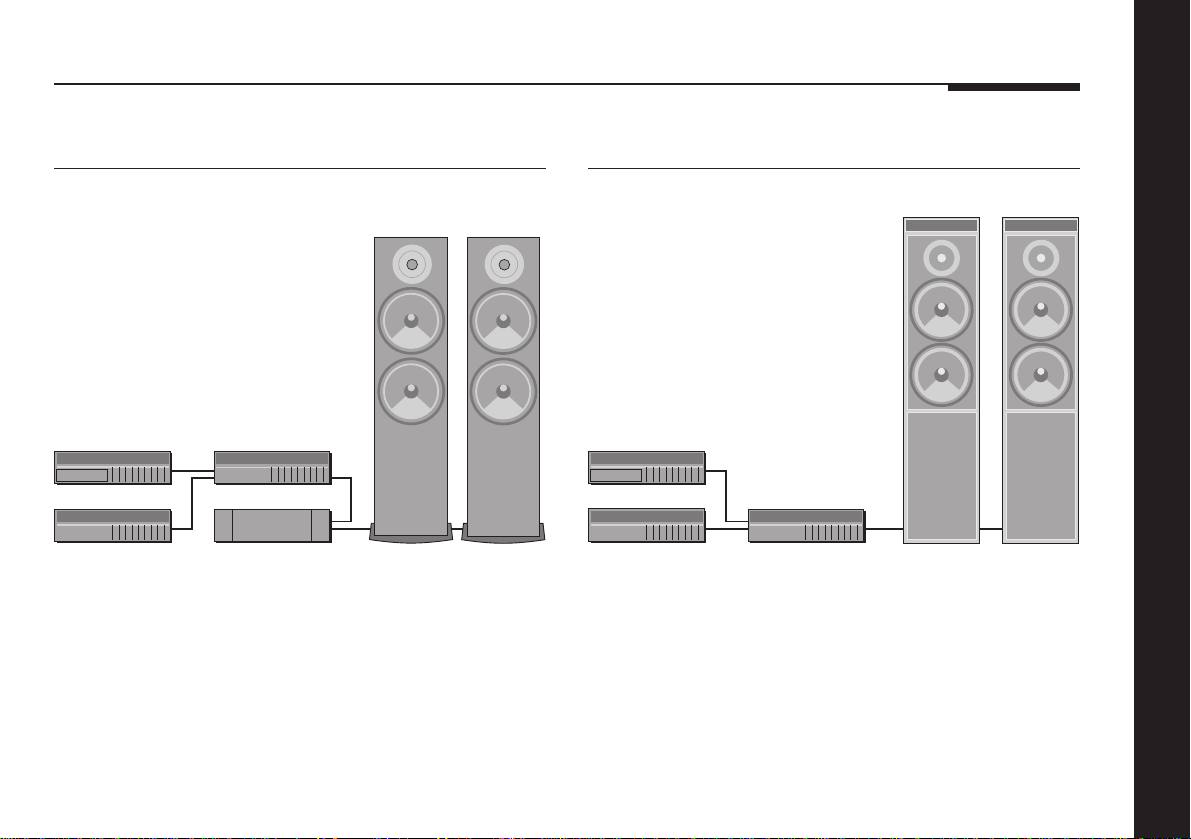
Sample configurations
506 20-Bit CD Player
A500
506
504
501
555
The 506 20-Bit CD Player is an integrated CD transport and
converter, providing both digital and analogue outputs.
The 506 20-Bit CD Player is ideally suited for use with the
Meridian 555 Stereo Power Amplifier and A500 Loudspeakers,
with control over the volume and source selection provided by
the 501 Control Unit. The 504 Stereo FM Tuner is an ideal
addition to the system if radio reception is required.
A500
500 Compact Disc Transport
DSP5000DSP5000
500
504
The 500 Compact Disc Transport provides a precision digital
output, and can drive DSP5000 Digital Loudspeakers directly.
A 562 Digital Controller can be added to cater for conventional
analogue sources, such as the 504 Stereo FM Tuner, and
provide source selection between up to 12 different analogue or
digital sources.
562
Introduction
3
Page 8
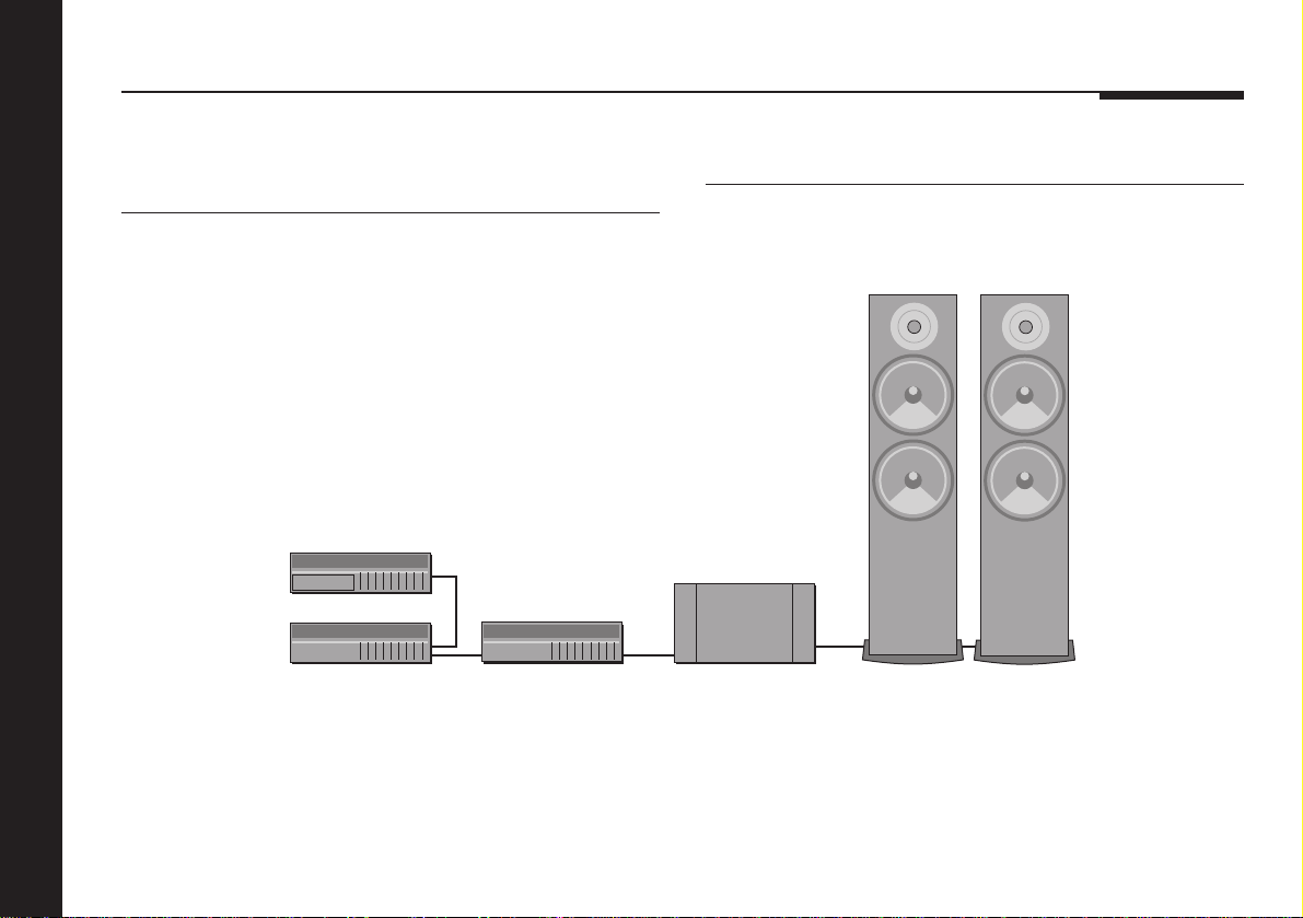
566 20-Bit Digital to Analogue Converter
502 Analogue Controller
Introduction
4
500
566
502
The digital output provided by the 500 Compact Disc Transport
can be decoded by the 566 20-Bit Digital to Analogue Converter
to provide a high-quality audio output for use with a
conventional audio preamplifier. The 566 20-Bit Digital to
Analogue Converter can also decode digital signals from other
sources, including LaserDisc players and Digital Audio Tape.
A500
557
A500
The 502 Analogue Controller is a full function preamplifier for use
with any analogue source, and includes balanced inputs to allow
you to take advantage of balanced sources, including the 566
20-Bit Digital to Analogue Converter. It provides balanced
outputs which are ideal for use with the 557 Stereo Power
Amplifier.
Page 9
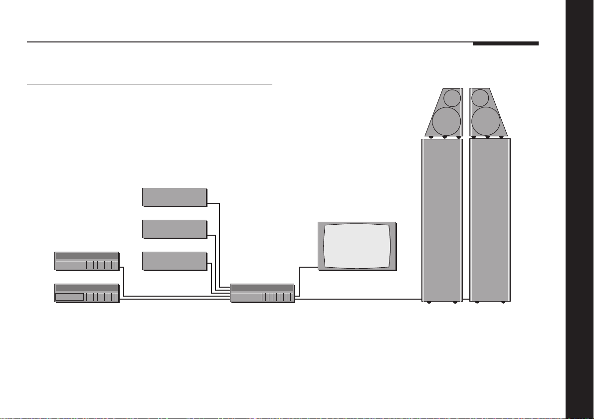
562V Multimedia Controller
DSP6000 DSP6000
Satellite
Video recorder
504
500
LaserDisc
562V
The 562V Multimedia Controller is the ideal control unit for use
with the Meridian DSP6000 Digital Loudspeakers.
It provides direct digital inputs for digital sources, such as the
500 Compact Disc Transport and LaserDisc sound, together
with precision Delta Sigma Analogue to Digital Conversion, for
Television
conventional analogue sources such as the 504 Stereo FM
Tuner and video sound.
It also includes video switching for CVBS and S-VHS signals,
such as from a satellite receiver, LaserDisc player, or video
recorder.
Introduction
5
Page 10

Specification and accessories
Introduction
Specification
Sensitivity 1.5µV mono, 23µV stereo, 100µV ult.
Distortion <0.2% mono, <0.4% stereo.
Noise -70dB.
Display Eight character alphanumeric dot
matrix display for station name,
frequency, and preset.
Stereo indicator.
Finish Black textured enamel and glass.
Dimensions 88mm x 321mm x 332mm
(3.46" x 12.64" x 13.07").
Weight 6.4kg (14lbs).
Input 87.0 – 108MHz.
FM 75Ω unbalanced.
Outputs Analogue: 2V.
Communications Two 5 pin 240° DIN sockets.
Consumption 20VA.
Meridian Audio reserves the right to amend product
specifications at any time.
Available accessories
The following accessories are available from your dealer:
❍Meridian System Remote.
❍Power cord Europe.
❍Power cord Canada and USA.
The Meridian System Remote provides access to all the facilities
provided by the 504 Stereo FM Tuner, including those available
from the front panel controls. In addition, it allows you to control
any other 500 Series units in your system.
If you have problems purchasing these items, you can order
them direct from Meridian Audio Limited, who can also supply a
range of digital cables suitable for connecting the 504 Stereo FM
Tuner to other equipment.
6
Page 11

Using the FM tuner
This chapter provides a visual summary of the functions of the FM tuner
in order to identify and help explain each of the controls which you will use
to operate the unit.
It also describes all aspects of using the FM tuner, beginning with
essential instructions such as switching on and selecting a station, to the
more advanced setup options.
Unless otherwise specified, each function is available from the front panel
or the remote.
Page 12
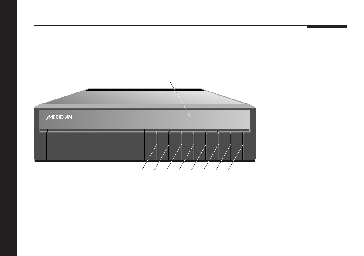
Front panel
1 V (Down)
Scans or steps down in
frequency.
Using the FM tuner
8
BOOTHROYD STUART
Stereo FM Tuner
504
Display
Radio 3
VA Display [Mono Store ]
12345678
2 A (Up)
Scans or steps up in
frequency.
3 Mono
Selects mono/stereo.
Off
4 Store
Stores a preset frequency.
5 Display
Selects the information
displayed.
6 [ (Previous)
Selects the previous
station.
7 ] (Next)
Selects the next station.
8 Off
Switches to standby.
Page 13

Selecting a station
During normal use the FM tuner should be left in the standby
state. This uses a negligible amount of electricity, but ensures
that the components of the FM tuner operate at maximum
efficiency from the moment you start listening to a station.
If you are not going to use the FM tuner for a period of several
days you should switch the unit completely off, at the back
panel, and disconnect it from the AC power supply.
To switch on from standby
● Press [ (Previous) or ] (Next).
● Switch on any other equipment connected to the FM tuner
which is not part of the Meridian 500 Series.
To select a preset station
● Press [ (Previous) or ] (Next) until the display shows the
station you want to listen to, or type the number of the preset
(remote only).
For example, for Radio 3
the display will show:
Radio 3
● Keeping either key held down will step through the preset
stations in turn.
Note that before using the FM tuner for the first time you may
need to set the preset frequencies for your area; see To
programme a preset, page 13.
To switch to standby
● Press Off.
The display will show:
If you have other Meridian 500 Series equipment connected to
the FM tuner, these units will also switch to standby.
.
Using the FM tuner
9
Page 14

Tuning manually
You use manual tuning to programme the preset stations, or to
select stations that you have not assigned to one of the presets.
The 504 Stereo FM Tuner is initially set up to use seek tuning. In
this mode it automatically searches for stations, and stops when
it finds one.
You can also select step tuning. In this mode you can step
through the frequencies in steps of 0.05MHz. To set step tuning
see To set up the FM tuner options, page 15.
You can adjust the criterion for adequate signal strength using
the Setup Stop Strength option; see To set up the FM tuner
options, page 15.
To search for a station
● Press A (Up) to seek upwards in frequency, or V (Down) to
seek downwards in frequency.
The FM tuner will switch to the frequency display, and then
search in the direction you have specified until a station is found.
The display will show the
station frequency.
93.O
Using the FM tuner
10
Page 15

Selecting stereo or mono
The 504 Stereo FM Tuner will automatically decode a stereo
transmission when one is received, and the front panel Stereo
indicator will appear.
You may wish to turn off the stereo decoder on a marginal
transmission, to reduce the background hiss or birdies.
The Mono setting can be stored with the station frequency in
presets; see Defining preset stations, page 12.
To switch to mono
● Press Mono.
The display will show the
current setting:
● Press Mono again.
The display will show:
The Stereo indicator will not be displayed.
Stereo
Mono
To switch to stereo
● Press Mono twice.
The display will show:
The Stereo indicator will be displayed if the transmission is
stereo.
Stereo
Using the FM tuner
11
Page 16
Defining preset stations
The FM tuner allows you to define up to 30 preset stations, so
that you can select them immediately from the front panel or
remote.
For convenience you can assign a label to the presets to make
them easy to identify. The 504 Stereo FM Tuner is supplied with
the following labels already set up:
Preset Label
1
2
3
4
Radio 1
Radio 2
Radio 3
Radio 4
Preset Label
5
6
7
8
You can also choose which preset station is selected when you
switch on the FM tuner; see To choose the station at switch-on
opposite.
Preset Label
Radio 5
Radio 6
Classic
Local 1
9
10
11
12
Local 2
ILR 1
ILR 2
ILR 3
Using the FM tuner
12
Page 17

To programme a preset
To choose the station at switch-on
● Press [ (Previous) or ] (Next) until the preset you want to
programme is displayed, or type the preset number (remote
only).
● Tune the station by pressing A (Up) or V (Down); see Tuning
manually, page 10.
● If the station is marginal, and you want it to be preset to
Mono, press Mono.
● Press Store.
The display will show:
The preset is now programmed to the station you tuned.
Stored
● Select the preset you want to choose.
● Press Store.
The display will show:
This station will now be selected when the tuner is turned on.
Stored
Using the FM tuner
13
Page 18
Choosing the display
To change the display
● Press Display.
Each time you press the key, the display will step between the
following display options:
Display Example
Preset label. This is the usual
display.
Blank.
Preset number and tuning
meter.
Preset number and frequency. This
is the usual display when tuning.
Using the FM tuner
Radio 3
3 ≤8≥
3 92.3
To use the tuning meter
● Press Display until the tuning meter is displayed.
This shows the preset number, the signal strength from 1 to 8,
and the tuning position.
The following table shows what the different displays mean:
Display What it means
≤≤5
≤8≥
5≥≥
≤≤1
● After tuning, revert to a normal preset or frequency display as
the tuning meter slightly degrades the output quality.
Below station; press A (Up) to
tune.
Strong station perfectly in tune.
Above station; press V (Down) to
tune.
No station.
14
Page 19
Setting up the FM tuner
For many users the only change they will want to make to the
standard operation of the 504 Stereo FM Tuner is to define the
preset stations.
However, the 504 Stereo FM Tuner contains several
customisable features that you can programme to suit your
requirements.
To set up the FM tuner options
● Turn off the FM tuner, using the power switch on the back
panel.
● Turn on the power again while holding down the Mono key on
the front panel.
The display will show:
It will then show the first setup option:
● Press Mono to move between the options.
● Press A (Up) or V (Down) to change the value of the current
option.
Setup
Max? 3O
The following table shows the options you can set up.
Option Initial value
Maximum number of
presets (1 to 30).
Tuning method
(Seektune or Steptune).
Stop strength (1 to 8).
Tuning meter (Y or N).
For more information about the tuning method and stop strength
see Tuning manually, page 10.
For more information about the tuning meter see To use the
tuning meter, opposite.
Max? 3O
Seektune
Stop= 4
Meter? Y
Using the FM tuner
15
Page 20

To set up the preset labels
If there was previously no label the display will be blank.
● Turn off the FM tuner, using the power switch on the back
panel.
● Turn on the power again while holding down the Store key on
the front panel.
The display will show:
It will then show the first preset
number…
…followed by the corresponding
preset label:
To alter a preset label
● Press ] (Next) or [ (Previous) to select the number of the
preset you want to alter.
After a short delay the existing
label is shown:
Using the FM tuner
Labels
1
•adio 1
•adio 3
A flashing block cursor shows which character you can change.
● Press A (Up) or V (Down) to change the character.
The character cycles through the symbols: 0 – 9, a – z, A – Z, .,
and space.
● Press Store to move on to the next character.
● When you have specified all eight characters press Store to
store the label.
The display will show:
● When you have finished defining labels, switch the power off
and on again to restore the FM tuner to normal operation.
Stored
16
Page 21

Setting up the FM tuner
This chapter explains how to install the FM tuner. It describes what you
should find when you unpack the FM tuner, how you should connect it to
your other audio equipment, and the siting constraints.
Before you begin installation, you should ensure that your FM tuner is the
correct voltage for your local AC supply. If it is not, do not try to install the
FM tuner, and contact your dealer.
You should not make any connections to the FM tuner or to any other
component in your system whilst the AC power supply is connected and
switched on.
Page 22

Unpacking
The 504 Stereo FM Tuner comes in a box containing the
following components:
❍504 Stereo FM Tuner.
❍1 power cord.
❍1 COMMS lead, to connect the FM tuner to another Meridian
500 Series unit.
❍1 RF connector.
❍This manual.
You are advised to retain the packing in case you need to
transport the unit.
To position the FM tuner
Do not place the FM tuner:
❍In direct sunlight.
❍Near heat sources, eg a radiator.
❍On top of a power amplifier, as the heat generated may
damage the FM tuner.
However, it can be stacked on a 500 Compact Disc Transport or
Setting up the FM tuner
18
506 20-Bit CD Player, if you have these Meridian components in
your system.
Radio interference
FCC Warning: This equipment generates and can radiate radio
frequency energy and if not installed and used correctly in
accordance with our instructions may cause interference to
radio communications or radio and television reception. It has
been type-tested and complies with the limits set out in Subpart
J, Part 15 of FCC rules for a Class B computing device. These
limits are intended to provide reasonable protection against
such interference in home installations.
EEC: This product has been designed to comply with the limits
set out in EN55013 and EN55020C.
Page 23
Connecting the FM tuner
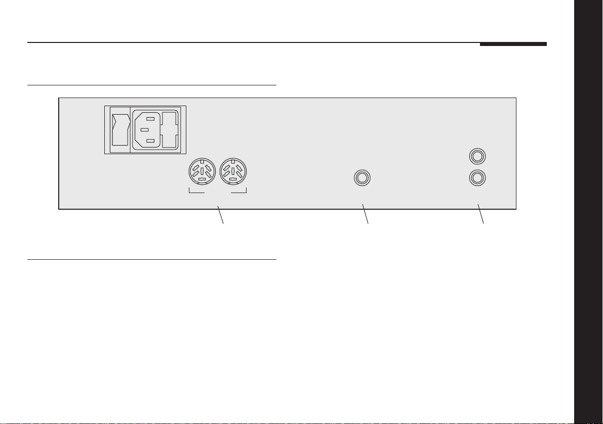
Back panel
OFF
ON
COMM
(Meridian Comms Only)
Comms
connections
To connect an antenna
A suitable VHF antenna or VHF cable signal must be connected
to the socket marked ‘RF input’ on the back of the tuner. You
are advised to use a high-quality, low-loss coaxial cable. Cables
which have a solid screen will give superior performance.
Please note that the antenna must be intended for unbalanced
(ie coaxial) connection. Antennas intended for, or connected
with ribbon cable are unsuitable. If your antenna uses a ribbon
cable then ask your dealer for a ‘balun’, or have it reconnected.
Ribbon cables are not acceptable proof against RF interference.
OUTPUT
L
R
RF Input, 75Ω
Antenna
input
Phono
outputs
The 504 Stereo FM Tuner is a very sophisticated unit, which will
deliver superb quality sound. However, unless the signal
delivered to the antenna socket of the 504 is of sufficient
strength and quality, you will not enjoy the maximum benefits of
your new tuner. We cannot emphasise enough the importance
of a good VHF antenna and downlead.
However, as reception conditions vary so much, it is impossible
to give more than broad advice, and we recommend, therefore,
that you consult your dealer or antenna supplier who will be
familiar with local conditions and will be able to advise you on
the right equipment for your installation.
Setting up the FM tuner
19
Page 24
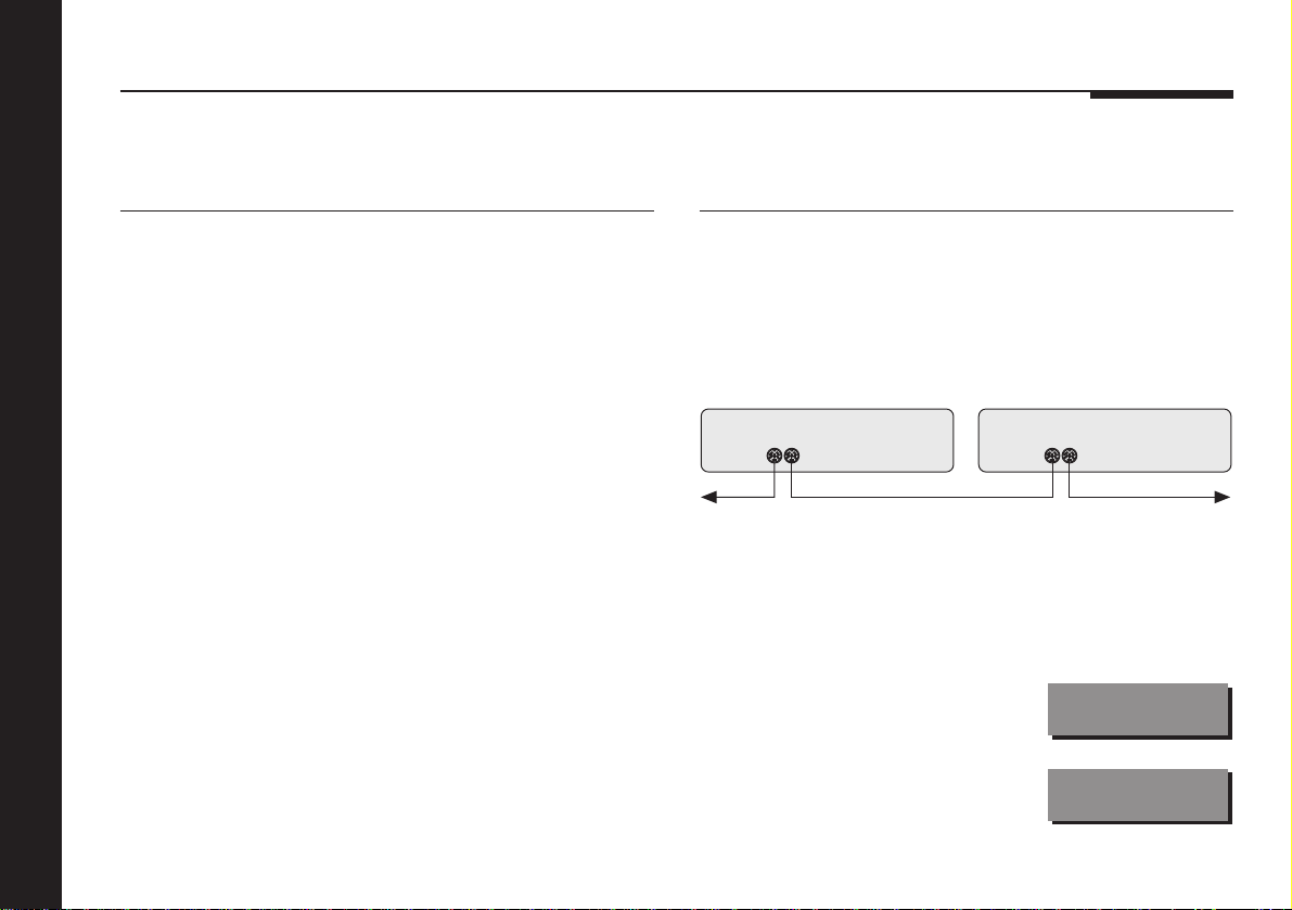
To connect to a conventional
preamplifier
To connect to other Meridian 500
Series equipment
● Connect the sockets marked OUTPUT L and R on the back
panel of the FM tuner to an appropriate input on your
preamplifier.
You should consult the manufacturer’s manual to determine
which input to use, but it will generally be labelled TUNER,
RADIO, or AUX.
You should either use a twin-screened audio cable, or a pair of
single-screened audio cables. These cables can have a
considerable effect on the quality of the sound, and you are
advised to seek your dealer’s advice on the best type of cables
for your system.
Setting up the FM tuner
20
● Connect one of the COMMS sockets on the back panel of the
FM tuner to one of the COMMS socket on another 500 Series
unit, using the 500 comms lead provided.
The sequence in which you connect the units is not important.
COMMS COMMS
Then configure the units with the following automatic setup
procedure:
● Switch all the units to standby.
● Press Clear on the remote.
Each unit will display:
One unit will then be designated as
the controller, and display:
Auto
Con.
Page 25

This is the unit that will respond to the remote.
All the other units will be configured
as non-controllers, and display:
Your system is now set up and ready for use.
● If for any reason the automatic setup does not give the
configuration you want, restore the default operation by
selecting Type 1 as described in To connect to Meridian 600
or 200 Series equipment, opposite.
● If you want to change the automatic setup configuration refer
to the Meridian 500 Series User Guide.
Note: Do not, under any circumstances, connect any equipment
other than Meridian 500, 600, or 200 Series to the socket
marked COMMS on the back of the FM tuner.
N.Con.
To connect to Meridian 600 or 200
Series equipment
If your system includes any Meridian 600 or 200 Series units,
with 600 COMMS or 200 COMMS sockets, you should set all
the 500 Series units to 200 COMMS operation using the
following procedure:
● Turn off the FM tuner, using the power switch on the back
panel.
● Turn on the power again while holding down the Off key on
the front panel.
The display will show the current
setup:
Press ] (Next) on the front panel
to change to Type 2:
● Switch the power off and on again to restore the FM tuner to
normal operation.
● To return to 500 COMMS operation repeat the above
procedure, and select Type 1.
Type 1
Type 2
Setting up the FM tuner
21
Page 26
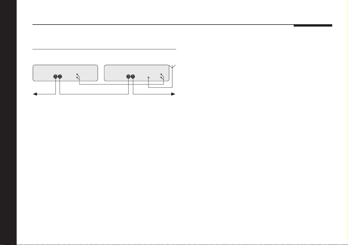
To connect to a 501 Control Unit
501 Control Unit
COMM COMMS
● Connect the sockets marked OUTPUT L and R on the back
panel of the FM tuner to the RADIO input on the back panel of
the 501 Control Unit.
Setting up the FM tuner
504 Stereo FM Tuner
RADIO OUTPUT
Audio lead
500 comms lead
RF
Antenna
22
Page 27

Troubleshooting
This section describes problems you may encounter when using
the FM tuner, and includes suggested solutions.
If these suggestions fail to cure the problem, please contact
your Meridian dealer for further assistance.
No standby display is shown
❍Check that your AC power supply is connected correctly.
❍Check that the ON OFF switch on the back panel is in the ON
position.
❍Check that the fuse on the FM tuner back panel and the fuse
in the unit’s power plug have not blown; see To change the
mains fuse, page 25.
Reception is poor
❍In many areas a particular transmission can be received on
several frequencies. Check to see if the same station can be
received with more signal-strength at a different frequency.
❍Check that the RF signal is of good quality.
❍Check that all the connections are correctly made.
❍Check that the antenna is of good quality, and has a coaxial
(unbalanced) output.
❍If the RF signal is coming from a head amplifier or distribution
amplifier, check that it is switched on.
There is a hum using the analogue
output
❍A ground-loop may be generated with associated equipment.
Check the grounding of associated units.
Setting up the FM tuner
23
Page 28

There is interference to radio and/or
television reception when the FM
tuner is switched on
Before following the steps below, ensure all units are switched
off first.
If this equipment does cause or suffer from interference to/from
radio or television reception then the following measures should
be tried:
❍Reorient the receiving aerial (or antenna) or route the antenna
cable of the receiver as far as possible from the 504 Stereo
FM Tuner and its cabling.
❍Ensure that the receiver uses well-screened antenna cable.
❍Relocate the receiver with respect to the FM tuner.
❍Connect the receiver and this product to different AC outlets.
Setting up the FM tuner
24
Page 29

Maintenance
Cleaning
When cleaning the FM tuner bear in mind that the front of the
FM tuner is plastic, and the display panel and lid are glass.
Disconnect the power cord before cleaning the unit.
Note: Do not use abrasive cleaners on any part of the FM tuner.
To clean the case, display panel, and
keypad
● Use a slightly damp cloth.
Ensure that no water is allowed to get inside the case, and do
not reconnect the power until you are certain that the FM tuner
is completely dry.
To clean the audio connections
The audio sockets on the back of the FM tuner are gold-plated
and need no cleaning if gold-plated phono plugs are used.
Otherwise, it is recommended that you unplug and reconnect
the plugs at least once a year. A proprietary contact cleaner can
be used to some advantage.
To change the mains fuse
Fuse
Spare
● Remove the mains connector, and pull out the drawer next to
the power input to access the fuses.
Before replacing a blown fuse, if possible ascertain the cause of
the failure.
The fuse drawer includes a spare fuse. This should be replaced
by one of the same rating.
Setting up the FM tuner
25
Page 30

Service and guarantee
Service
The Meridian 500 Series of hi-fi components have been carefully
designed to give years of untroubled service. There are no userserviceable parts inside the case, nor do the units require any
form of maintenance.
In the unlikely event that your FM tuner fails to function correctly,
it should be returned, in its original packaging, to your Meridian
dealer.
In case of difficulty within the UK or USA please contact the
appropriate sales and service address shown on page ii.
In case of difficulty outside the UK or USA, contact the importing
agent for the territory. A list of Meridian agents abroad is
available from Meridian Audio.
No responsibility can be accepted for the FM tuner whilst in
transit to the factory or an agent, and customers are therefore
advised to insure the unit.
When seeking service under guarantee, proof of the date of
Setting up the FM tuner
purchase will be required.
Guarantee
The 504 Stereo FM Tuner is guaranteed against defects in
material and workmanship for 2 years from the date of purchase.
The guarantee is void if the 504 Stereo FM Tuner has been
subject to misuse, accident, or negligence, or has been
tampered with or modified in any way without the written
authorisation of Meridian Audio Limited. Note that connecting
anything other than the correct network lead to the COMMS
sockets may cause damage to the 504 Stereo FM Tuner which
will not be covered by this guarantee. Attempted servicing by
unauthorised people may also invalidate this guarantee. Labour
and carriage charges are not covered unless by local agreement.
Outside the UK, local warranty liability is restricted to equipment
purchased within the territory. Our agents abroad are only under
contractual obligation to service under guarantee equipment
sold through them. They are entitled to make a non-refundable
charge for any service carried out on other equipment.
This guarantee does not limit your statutory rights within the
United Kingdom.
26
Page 31

Index
A
Accessories 6
C
Changing the display 14
Cleaning
the audio connections 25
the case 25
Components 18
Connecting
to a 501 Control Unit 22
to a conventional preamplifier 20
to an antenna 19
to Meridian 500 Series
equipment 20
to Meridian 600 and 200 Series
equipment 21
F
Front panel controls 8
Fuse, replacing 25
G
Guarantee 26
I
Installing 18
Introduction 1
L
Labels, defining 16
M
Maintenance 25
Meridian 500 Series 2
500 Compact Disc Transport 3, 4
501 Control Unit 3
502 Analogue Controller 4
504 Stereo FM Tuner 3
506 20-Bit CD Player 3
555 Stereo Power Amplifier 3
557 Stereo Power Amplifier 4
562 Digital Controller 3
562V Multimedia Controller 5
563 Digital to Analogue Converter 4
566 20-Bit Digital to Analogue
Converter 4
communications 2
Meridian 500 Series operation,
setting 20
Meridian 600 and 200 Series
operation, setting 21
Meridian A500 Loudspeakers 3, 4
Meridian DSP5000 Digital
Loudspeakers 3
Meridian DSP6000 Digital
Loudspeakers 5
Meridian System Remote 2
O
Outputs 19
P
Positioning 18
Preset stations
defining 12
labels 16
Programming presets 13
R
Radio interference 18
S
Searching for a station 10
Seektune 10, 15
Selecting
a preset station 9
a station 9
mono 11
stereo 11
Service 26
Setting up the FM tuner 15
for 500 Series operation 20
for 600 and 200 Series operation 21
Setting up the preset labels 16
Specification 6
Standby mode 9
Index
27
Page 32

Stations
defining presets 12
selecting 9
tuning 10
Steptune 10, 15
Stop strength 10, 15
Switching on from standby 9
Switching to standby 9
T
Troubleshooting 23
Tuning manually 10
Tuning meter 14
Tuning method 10, 15
U
Unpacking 18
28
Index
 Loading...