

Page 1

user guide
Meridian 555 Power Amplifier
Page 2

Preface
ii
Sales and service in the UK
Meridian Audio Ltd
Stonehill
Stukeley Meadows
Cambs
PE18 6ED
England
Tel (01480) 52144
Fax (01480) 459934
World Wide Web
http://www.meridian.co.uk
Sales and service in the USA
Meridian America Inc
3800 Camp Creek Parkway
Building 2400
Suite 112
Eastpoint
Atlanta
GA 30331
Tel (404) 344 7111
Fax (404) 346 7111
Designed and
manufactured in the UK by
Digital Gramophone and Wireless Ltd
Stonehill
Stukeley Meadows
Huntingdon
PE18 6ED
England
Copyright © 1993-1995 Digital
Gramophone and Wireless Ltd
Part no: 555/1
This guide was produced by
Human-Computer Interface Ltd,
Cambridge, England.
Page 3

Contents
Introduction 1
Introduces the 555 Stereo Power
Amplifier, and provides an overview of the
other products available in the Meridian
500 Series.
The Meridian 500 Series ........................ 2
Sample configurations ........................... 3
Specification and accessories ............... 6
Setting up the Stereo
Power Amplifier 7
Describes how to unpack, install, and use
the stereo power amplifier, and explains
what you should do if your stereo power
amplifier requires servicing.
Unpacking .............................................. 8
Connecting the stereo power amplifier .. 9
Troubleshooting ..................................... 12
Maintenance .......................................... 13
Service and guarantee ........................... 14
Index ...................................................... 15
Preface
iii
Page 4

Preface
iv
Page 5

Introduction
In choosing the 555 Stereo Power Amplifier you have acquired a
component that combines major advances in audio and engineering
design.
The 555 Stereo Power Amplifier uses a unique feedback topology and
precision local error correction system. It is designed and constructed in
dual mono format, including a massive twin wound toroidal transformer,
and the unit has full thermal, load, and DC protection.
This guide is designed to enable you to obtain the best possible results
from the unit in conjunction with the other units in your system.
Page 6

The Meridian 500 Series
Introduction
The Meridian 500 Series is a unique system of digital, analogue,
and video components designed to meet the demand for
absolute quality, ease of use, and lasting value.
The flexibility of the Meridian 500 Series is such that you can
assemble a system as simple or as complex as you need,
perfectly suited to your musical and environmental requirements,
and with the ability to add to it or change it at a later date should
your requirements change. The 500 Series is also compatible
with the existing Meridian 200 Series and 600 Series
components.
Each Meridian 500 Series component is housed in a matching
slim line case. Front panel controls provide access to the most
important functions, and the full range of functions is available
from the Meridian System Handset using a simple and intuitive
control interface.
500 Series communications
The Meridian 500 Series includes a sophisticated
communications link, to ensure that any configuration of units
will work together as a fully integrated system.
The 500 Series communications system allows you to control
any combination of units using a single handset, and ensures
that your commands from the handset are interpreted
unambiguously. Any unit can be designated as the controller for
the system, allowing you to position the other units out of range
from the handset beam if desired. It also allows all the units to
be switched off from the front panel of any unit in the system.
Professional features
The 500 Series also includes features for professional users,
including RS232 computer control (501, 562, and DSP5000), and
balanced outputs (563).
The following pages give examples of four suggested
configurations to illustrate the flexibility of the Meridian 500
Series.
2
Page 7
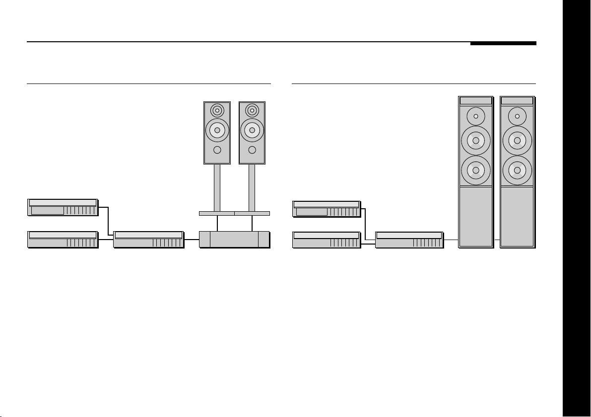
Sample configurations
506 Compact Disc Player
A2A2
506
501 M60 M60504 555
The 506 Compact Disc Player is an integrated CD transport and
converter, providing both digital and analogue outputs.
The 506 Compact Disc Player is ideally suited for use with the
Meridian 555 Stereo Power Amplifier and A2 Loudspeakers, with
control over the volume and source selection provided by the
501 Remote Control Preamplifier.
500 Compact Disc Transport
500
504
562
The 500 Compact Disc Transport provides a precision digital
output, and can drive DSP5000 Digital Loudspeakers directly.
A 562 Digital Controller can be added to cater for conventional
analogue sources, such as the 504 FM Tuner, and provide
source selection between up to 12 different analogue or digital
sources.
DSP5000 DSP5000
Introduction
The 504 FM Tuner is an ideal addition to the system if radio
reception is required.
3
Page 8
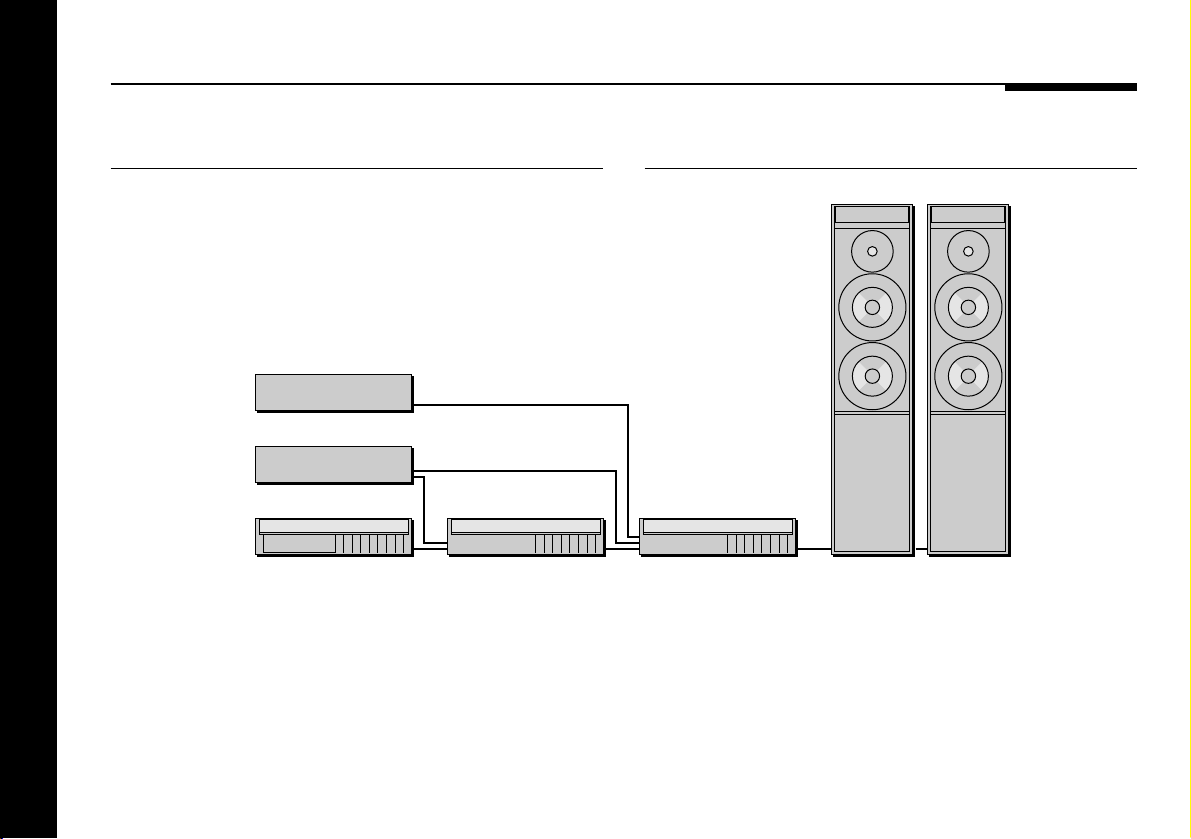
563 Digital to Analogue Converter
VIDEO
LASERDISC
501V Control Unit
Introduction
4
The digital output provided by the 500 Compact Disc Transport
can be decoded by the 563 Digital to Analogue converter to
provide a high-quality audio output for use with a conventional
audio preamplifier.
The 563 Digital to Analogue Converter can also decode digital
signals from other sources, including LaserDisc players and
Digital Audio Tape.
501V500 563
M60 M60
The 501V Control Unit is a full function preamplifier for use with
any analogue source, and includes video switching for complete
control of systems that include video sources such as a
LaserDisc player and video recorder.
It provides a high-quality audio output ideal for use with the
Meridian M60 Active Loudspeakers.
Page 9
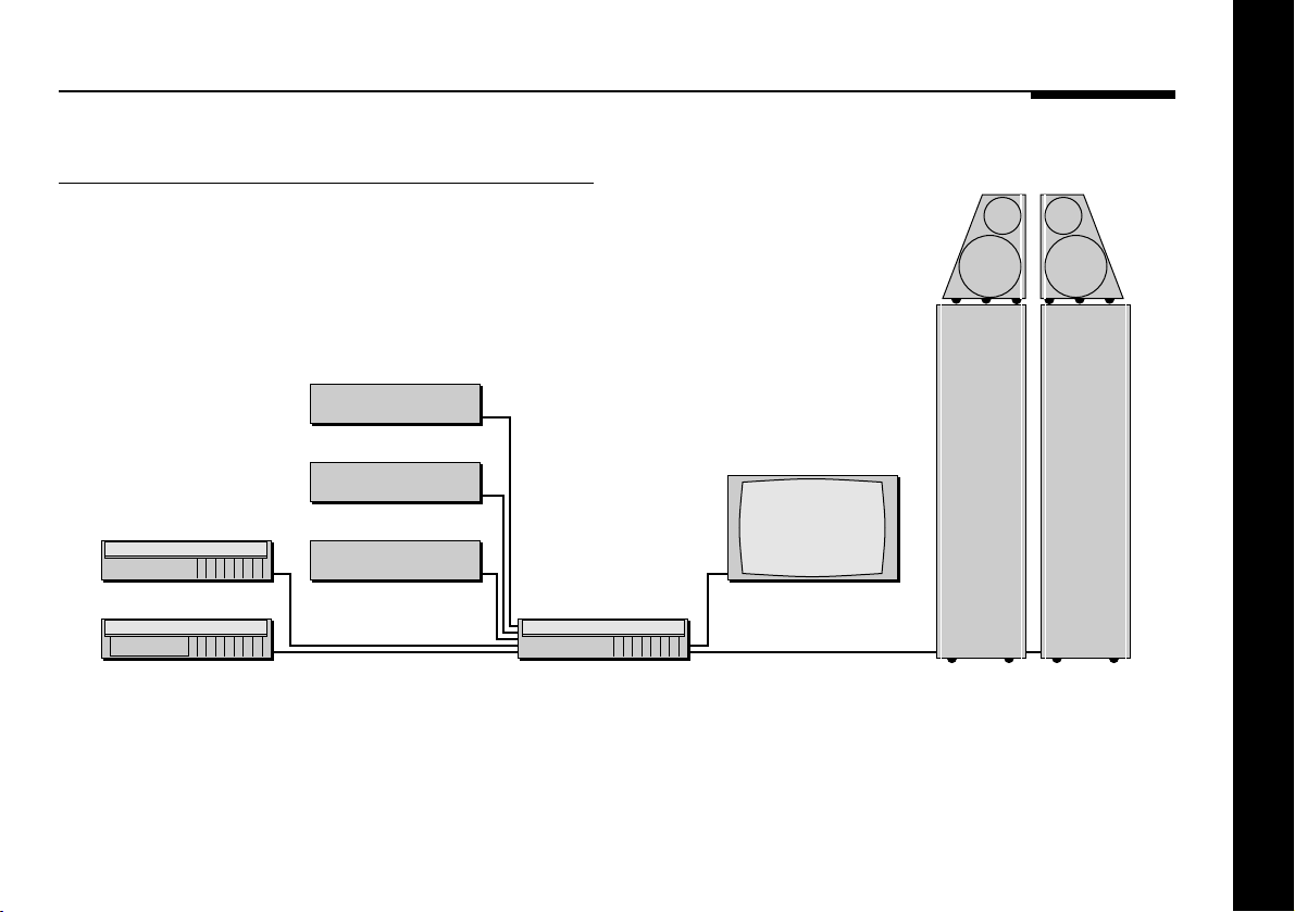
562V Multimedia Controller
SATELLITE
VIDEO
504
500 562V
LASERDISC
The 562V Multimedia Controller is the ideal control unit for use
with the Meridian D6000 Digital Loudspeakers.
It provides direct digital inputs for digital sources, such as the
500 Compact Disc Transport and LaserDisc sound, together
with precision Delta Sigma Analogue to Digital Conversion, for
TV
D6000 D6000
conventional analogue sources such as the 504 FM Tuner and
video sound.
It also includes video switching for CVBS and S-VHS signals,
such as from a satellite receiver, LaserDisc player, or video
recorder.
Introduction
5
Page 10

Specification and accessories
Specification
Input 1.4V RMS.
Output 65W per channel into 8Ω.
100W per channel into 4Ω.
Distortion Less than 0.05%.
Noise Less than -90dB.
Finish Black textured enamel and glass.
Heatsinks black painted aluminium.
Dimensions 88mm x 321mm x 320mm
(3.46" x 12.64" x 12.6").
Weight 9kg.
Consumption 30VA quiescent, 300VA max.
Meridian Audio reserves the right to amend product
specifications at any time.
Available accessories
The following accessories are available from your dealer:
❍Power cord Europe.
❍Power cord Canada and USA.
If you have problems purchasing these items, you can order
them direct from Meridian Audio Limited, who can also supply a
range of cables suitable for connecting the 555 Stereo Power
Amplifier to other equipment.
Introduction
6
Page 11

Setting up the Stereo Power Amplifier
This chapter explains how to install the stereo power amplifier. It
describes what you should find when you unpack the stereo power
amplifier, how you should connect it to your other audio equipment, and
the siting constraints.
You should not make any connections to the stereo power amplifier or to
any other component in your system whilst the AC power supply is
connected and switched on.
Page 12

Unpacking
The 555 Stereo Power Amplifier comes in a box containing the
following components:
❍555 Stereo Power Amplifier.
❍1 power cord.
❍This manual.
You are advised to retain the packing in case you need to
transport the unit.
Before connecting power
Before you begin installation you should ensure that your stereo
power amplifier is set to the correct voltage for your local AC
supply. If it is not, do not try to install the unit, and contact your
dealer.
Do not make connections, or insert or remove plugs, while
the unit is connected to the supply and switched on, as the
transients generated could damage the loudspeakers.
Once set up, the stereo power amplifier can be left switched on
as it consumes negligible power when not in use.
If you are not going to use the stereo power amplifier for a
period of several days you should switch the unit completely off,
at the rear panel, and disconnect it from the AC power supply.
To position the stereo power amplifier
During normal operation the heatsinks, ie the fins at each end of
the case, may become quite hot. The stereo power amplifier
should therefore be positioned to allow a free flow of air around
the fins.
Do not place the stereo power amplifier:
❍In direct sunlight.
❍Near heat sources, eg a radiator.
❍Stacked with any other audio products, as the heat it
generates may damage the other products.
Setting up the Stereo Power Amplifier
8
Page 13
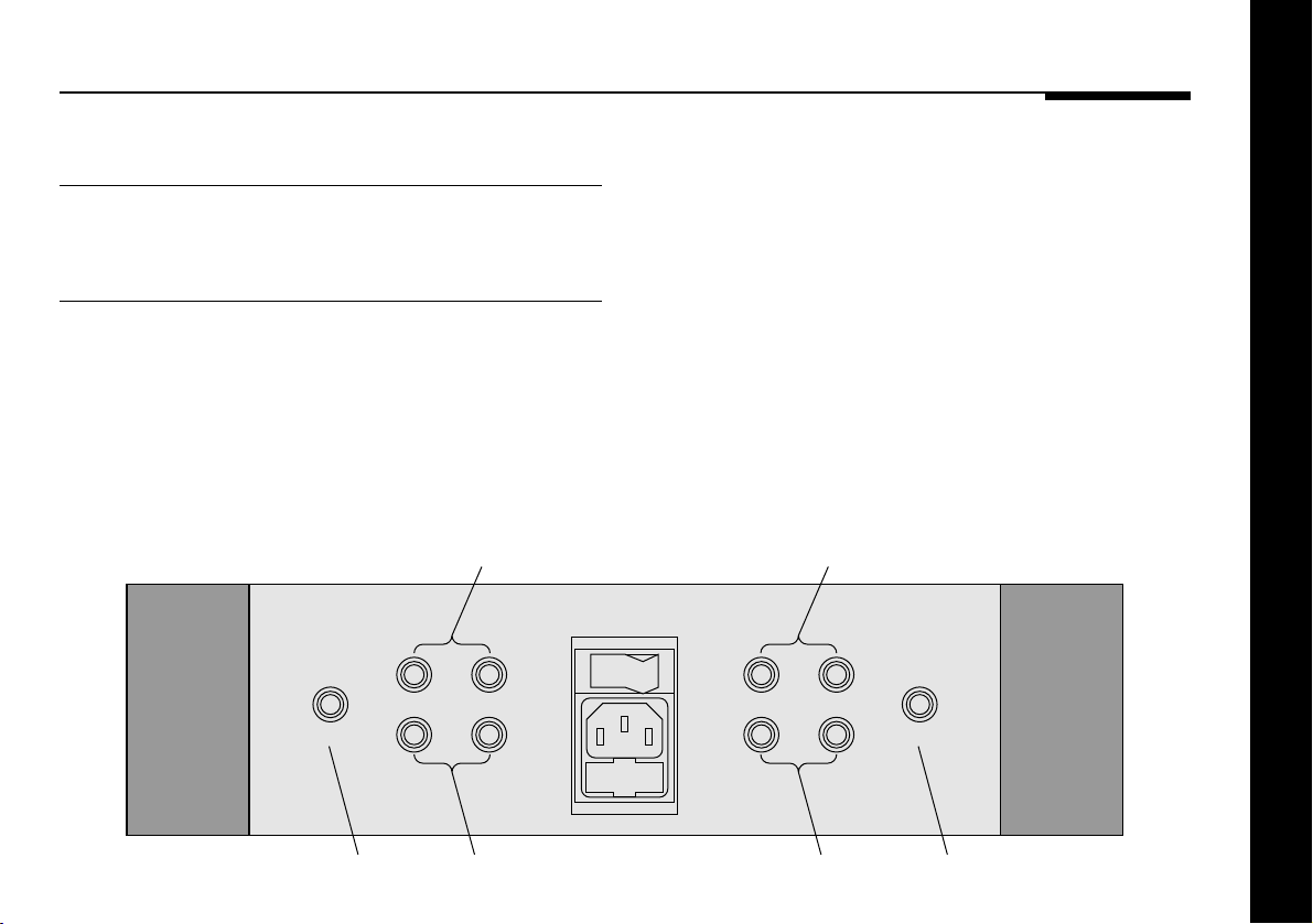
Connecting the stereo power amplifier
Rear panel
The diagram below shows the rear panel connections.
Outputs
The output terminals should be connected to loudspeakers of
4Ω to 15Ω, using either banana plug or bare wire connections.
Each channel of the 555 Stereo Power Amplifier provides twin
outputs for bi-wiring. On speakers that provide separate
Output + (L)
OFF ON
INPUT INPUT
connections to the bass/mid and tweeter units this allows the
units to be connected independently to the stereo power
amplifier, for optimum sound quality.
Alternatively, for loudspeakers providing a single pair of inputs,
either of the output terminals can be used.
Setting up the Stereo Power Amplifier
Output + (R)
Input (L)
Output - (L) Input (R)
Output - (R)
9
Page 14
To connect to a conventional
preamplifier
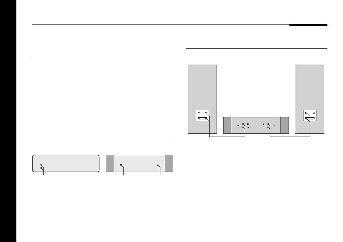
● Connect the sockets marked INPUT on the rear panel of the
stereo power amplifier to the outputs from your preamplifier.
You should either use a twin-screened audio cable, or a pair of
single-screened audio cables. These cables can have a
considerable effect on the quality of the sound, and you are
advised to seek your dealer’s advice on the best type of cables
for your system.
To connect to a 501 Control Unit
To connect to A2 Loudspeakers
A2 LoudspeakerA2 Loudspeaker
555 Stereo Power Amplifier
501 Control Unit 555 Stereo Power Amplifier
OUTPUT
● Connect the sockets marked OUTPUT L and R on the rear
panel of the 501 Control Unit to the INPUT sockets on the rear
panel of the 555 Stereo Amplifier.
Setting up the Stereo Power Amplifier
10
Audio lead
INPUT INPUT
● Use the links provided to bridge the BASS/MID and TWEETER
terminals on the rear of each loudspeaker.
● Connect one of each pair of the red and black terminals on
the rear panel of the 555 Stereo Power Amplifier to the red
and black terminals on the A2 Loudspeakers.
Page 15
To bi-wire to A2 Loudspeakers
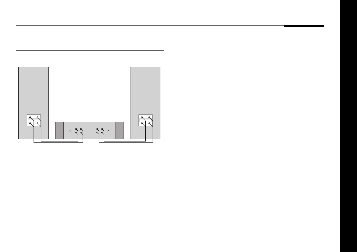
● Connect the TWEETER red and black terminals from each
loudspeaker to the other pair of red and black terminals on the
A2 LoudspeakerA2 Loudspeaker
appropriate channel of the stereo power amplifier.
555 Stereo Power Amplifier
● If necessary, remove the links bridging the BASS/MID and
TWEETER terminals on the rear of each loudspeaker.
● Connect the BASS/MID red and black terminals from each
loudspeaker to the red and black terminals on the appropriate
channel of the stereo power amplifier, using twin loudspeaker
cable.
Setting up the Stereo Power Amplifier
11
Page 16

Troubleshooting
This section describes problems you may encounter when using
the stereo power amplifier, and includes suggested solutions.
If these suggestions fail to cure the problem, please contact
your Meridian dealer for further assistance.
No front panel indicator is shown
❍Check that your AC power supply is connected correctly.
❍Check that the ON OFF switch on the rear panel is in the ON
position.
❍Check that the fuse on the stereo power amplifier rear panel
and the fuse in the unit’s power plug have not blown; see To
change the mains fuse, page 13.
The sound has cut out
The 555 Stereo Power Amplifier includes a thermal shutdown,
which mutes the output if the amplifier becomes too hot.
❍Leave the amplifier for a few minutes to cool down, and the
sound will come back on.
The 555 Stereo Power Amplifier also includes a power circuit
breaker to protect the loudspeakers.
❍Check the system for the cause of the cut out.
❍Switch off, wait 5 seconds, then switch on to reset the power.
Setting up the Stereo Power Amplifier
12
Page 17
Maintenance
Cleaning
When cleaning the stereo power amplifier bear in mind that the
front of the unit is metal, and the lid is glass.
Disconnect the power cord before cleaning the unit.
Note: Do not use abrasive cleaners on any part of the stereo
power amplifier.
To clean the case
● Use a slightly damp cloth.
Ensure that no water is allowed to get inside the case, and do
not reconnect the power until you are certain that the stereo
power amplifier is completely dry.
To clean the audio connections
The audio sockets on the rear of the stereo power amplifier are
gold-plated and need no cleaning if gold-plated phono plugs are
used. Otherwise, it is recommended that you unplug and
reconnect the plugs at least once a year. A proprietary contact
cleaner can be used to some advantage.
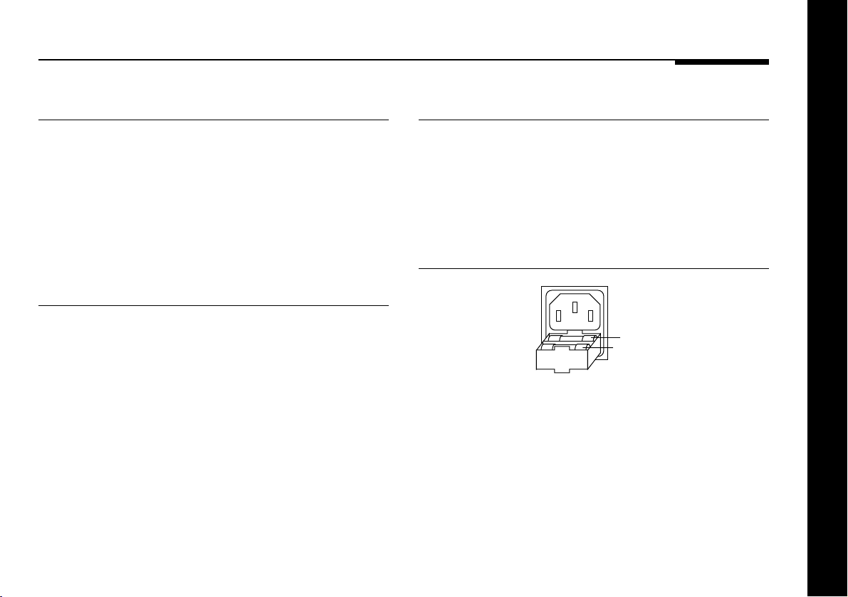
To change the mains fuse
Fuse
Spare
● Remove the mains connector, and pull out the drawer next to
the power input to access the fuses.
Before replacing a blown fuse, if possible ascertain the cause of
the failure.
The fuse drawer includes a spare fuse. This should be replaced
by one of the same rating.
Setting up the Stereo Power Amplifier
13
Page 18

Service and guarantee
Service
The Meridian 500 Series of hi-fi components have been carefully
designed to give years of untroubled service. There are no userserviceable parts inside the case, nor do the units require any
form of maintenance.
In the unlikely event that your stereo power amplifier fails to
function correctly, it should be returned, in its original
packaging, to your Meridian dealer.
In case of difficulty within the UK or USA please contact the
appropriate sales and service address shown on page ii.
In case of difficulty outside the UK or USA, contact the importing
agent for the territory. A list of Meridian agents abroad is
available from Meridian Audio.
No responsibility can be accepted for the stereo power amplifier
whilst in transit to the factory or an agent, and customers are
therefore advised to insure the unit.
When seeking service under guarantee, proof of the date of
Setting up the Stereo Power Amplifier
purchase will be required.
Guarantee
The 555 Stereo Power Amplifier is guaranteed against defects in
material and workmanship for 2 years from the date of purchase.
The guarantee is void if the 555 Stereo Power Amplifier has been
subject to misuse, accident, or negligence, or has been
tampered with or modified in any way without the written
authorisation of Meridian Audio Limited. Attempted servicing by
unauthorised people may also invalidate this guarantee. Labour
and carriage charges are not covered unless by local agreement.
Outside the UK, local warranty liability is restricted to equipment
purchased within the territory. Our agents abroad are only under
contractual obligation to service under guarantee equipment
sold through them. They are entitled to make a non-refundable
charge for any service carried out on other equipment.
This guarantee does not limit your statutory rights within the
United Kingdom.
14
Page 19

Index
A
Accessories 6
B
Bi-wire connection 9, 11
C
Cleaning
the audio connections 13
the case 13
Components 8
Connecting
to a 501 Control Unit 10
to a conventional preamplifier 10
to A2 Loudspeakers 10, 11
F
Fuse, replacing 13
G
Guarantee 14
H
Heat generated during
operation 8
I
Installing 8
Introduction 1
M
Maintenance 13
Meridian 500 Series 2
500 Compact Disc Transport 3
501 Remote Control Preamplifier 3
501V Control Unit 4
504 FM Tuner 3
506 Compact Disc Player 3
555 Stereo Power Amplifier 3
562 Digital Controller 3
562V Multimedia Controller 5
563 Digital to Analogue Converter 4
communications 2
Meridian A2 Loudspeakers 3
Meridian D6000 Digital
Loudspeakers 5
Meridian DSP5000 Digital
Loudspeakers 3
Meridian M60 Active
Loudspeakers 4
Meridian System Handset 2
O
Outputs 9
Overheating 8, 12
P
Positioning 8
S
Service 14
Sound has cut out 12
Specification 6
Switching on 8
T
Thermal protection 12
Troubleshooting 12
U
Unpacking 8
Index
15
Page 20

16
Index
 Loading...