

Page 1

user guide
Meridian 551 Integrated Amplifier
Page 2

Preface
ii
Sales and service in the UK
Meridian Audio Ltd
Stonehill
Stukeley Meadows
Cambs
PE18 6ED
England
Tel (01480) 52144
Fax (01480) 459934
World Wide Web
http://www.meridian.co.uk
Sales and service in the USA
Meridian America Inc
3800 Camp Creek Parkway
Building 2400
Suite 112
Atlanta
GA 30331
Tel (404) 344 7111
Fax (404) 346 7111
Designed and
manufactured in the UK by
Digital Gramophone and Wireless Ltd
Stonehill
Stukeley Meadows
Cambs
PE18 6ED
England
Copyright © 1993–1996
Digital Gramophone and Wireless Ltd
Part no: 551/2
This guide was produced by
Human-Computer Interface Ltd,
Cambridge, England.
Page 3

Contents
Introduction 1
Introduces the 551 Integrated Amplifier,
and provides an overview of the other
products available in the Meridian 500
Series.
The Meridian 500 Series ........................ 2
Sample configurations ........................... 3
Specification and accessories ............... 6
Using the integrated
amplifier 9
Provides step-by-step instructions on how
to operate the integrated amplifier, using
either the front panel or the Meridian
System Handset.
Front panel............................................. 10
Selecting a source ................................. 11
Adjusting the volume ............................. 12
Changing the display and balance ........ 13
Recording a source................................ 14
Customising the
integrated amplifier 15
Describes how to set up the integrated
amplifier in your preferred configuration.
Choosing standard settings................... 16
Configuring the sources......................... 18
Examples of configuring the
sources .................................................. 20
Programming levels ............................... 22
Specifying information about
your system ........................................... 24
Preface
iii
Page 4

Setting up the integrated
amplifier 25
Describes how to unpack and install the
integrated amplifier, and explains what you
should do if your integrated amplifier
requires servicing.
Unpacking.............................................. 26
Connecting the integrated amplifier ...... 27
Troubleshooting ..................................... 31
Maintenance .......................................... 33
Service and guarantee ........................... 34
Index ...................................................... 35
Preface
iv
Page 5

Introduction
In choosing the 551 Integrated Amplifier you have acquired a component
that combines major advances in audio and engineering design. It
combines a full function preamplifier with a high performance power
amplifier.
The preamplifier provides six audio inputs, each of which can be
individually adjusted for sensitivity, and identified on the four-character
alpha-numeric display. A very high quality MC or MM phono stage is
available as an option for the dedicated LP input.
The power amplifier uses a unique feedback topology and precision local
error correction system. It is designed and constructed in dual mono
format, including a massive twin wound toroidal transformer.
This guide is designed to enable you to obtain the best possible results from
the unit. If you have just purchased the 551 Integrated Amplifier you should
first turn to the chapter Setting up the integrated amplifier, page 25, which
explains how to unpack and install the integrated amplifier correctly.
Page 6

The Meridian 500 Series
The Meridian 500 Series is a unique system of digital, analogue,
and video components designed to meet the demand for
absolute quality, ease of use, and lasting value.
The flexibility of the Meridian 500 Series is such that you can
assemble a system as simple or as complex as you need,
perfectly suited to your musical and environmental requirements,
and with the ability to add to it or change it at a later date should
your requirements change. The 500 Series is also compatible
with the existing Meridian 200 Series and 600 Series
components.
Each Meridian 500 Series component is housed in a matching
slim line case. Front panel controls provide access to the most
important functions, and the full range of functions is available
from the Meridian System Remote using a simple and intuitive
control interface.
500 Series communications
The Meridian 500 Series includes a sophisticated
communications link, to ensure that any configuration of units
will work together as a fully integrated system.
The 500 Series communications system allows you to control
any combination of units using a single remote, and ensures that
your commands from the remote are interpreted unambiguously.
The communications system also allows you to extend your hi-fi
system into two or three rooms, with the ability to control the
sources in one room from the controller in another room.
Professional features
The 500 Series also includes features for professional users,
including RS232 computer control and balanced connections.
The following pages give examples of four suggested
configurations to illustrate the flexibility of the Meridian 500
Series.
Introduction
2
Page 7
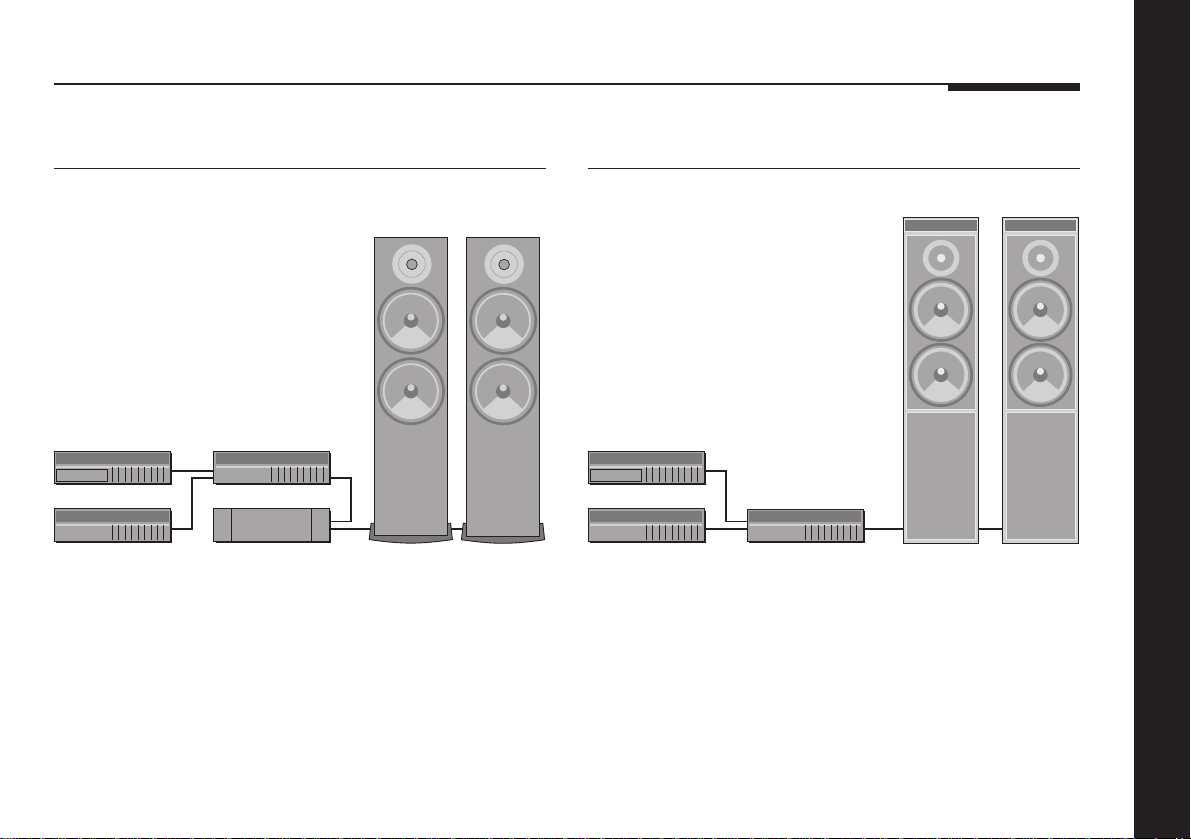
Sample configurations
506 20-Bit CD Player
A500
506
504
501
555
The 506 20-Bit CD Player is an integrated CD transport and
converter, providing both digital and analogue outputs.
The 506 20-Bit CD Player is ideally suited for use with the
Meridian 555 Stereo Power Amplifier and A500 Loudspeakers,
with control over the volume and source selection provided by
the 501 Control Unit. The 504 Stereo FM Tuner is an ideal
addition to the system if radio reception is required.
A500
500 Compact Disc Transport
DSP5000DSP5000
500
504
The 500 Compact Disc Transport provides a precision digital
output, and can drive DSP5000 Digital Loudspeakers directly.
A 562 Digital Controller can be added to cater for conventional
analogue sources, such as the 504 Stereo FM Tuner, and
provide source selection between up to 12 different analogue or
digital sources.
562
Introduction
3
Page 8
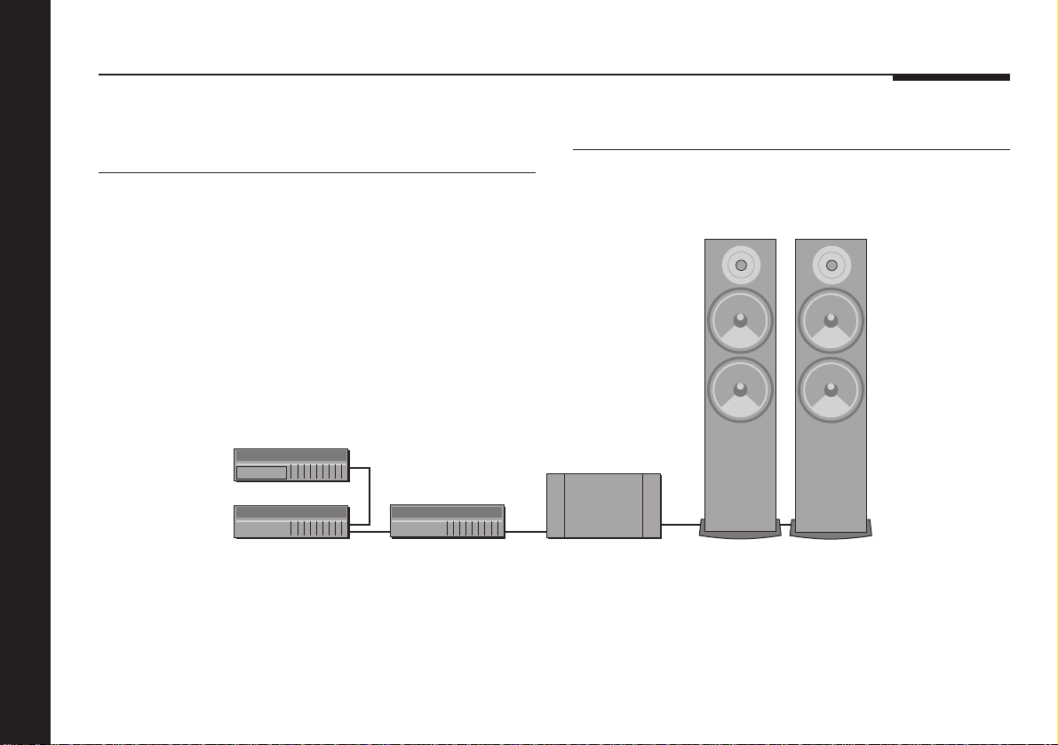
566 20-Bit Digital to Analogue Converter
502 Analogue Controller
Introduction
4
500
566
502
The digital output provided by the 500 Compact Disc Transport
can be decoded by the 566 20-Bit Digital to Analogue Converter
to provide a high-quality audio output for use with a
conventional audio preamplifier. The 566 20-Bit Digital to
Analogue Converter can also decode digital signals from other
sources, including LaserDisc players and Digital Audio Tape.
A500
557
A500
The 502 Analogue Controller is a full function preamplifier for use
with any analogue source, and includes balanced inputs to allow
you to take advantage of balanced sources, including the 566
20-Bit Digital to Analogue Converter. It provides balanced
outputs which are ideal for use with the 557 Stereo Power
Amplifier.
Page 9
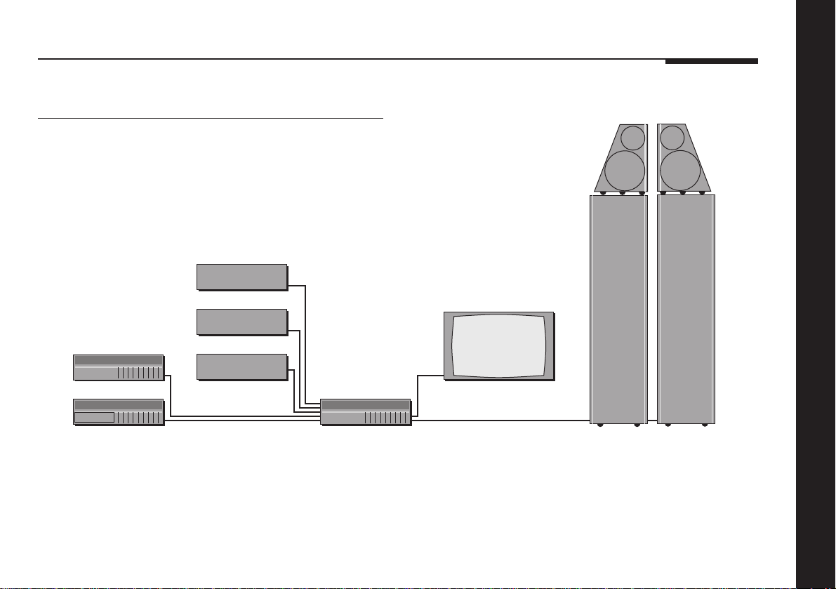
562V Multimedia Controller
DSP6000 DSP6000
Satellite
Video recorder
504
500
LaserDisc
562V
The 562V Multimedia Controller is the ideal control unit for use
with the Meridian DSP6000 Digital Loudspeakers.
It provides direct digital inputs for digital sources, such as the
500 Compact Disc Transport and LaserDisc sound, together
with precision Delta Sigma Analogue to Digital Conversion, for
Television
conventional analogue sources such as the 504 Stereo FM
Tuner and video sound.
It also includes video switching for CVBS and S-VHS signals,
such as from a satellite receiver, LaserDisc player, or video
recorder.
Introduction
5
Page 10

Specification and accessories
Introduction
6
Specification
MM input option Sensitivity adjustable 0.5 – 3mV for
5cm/s @ 1kHz.
Overload point 47mV @ 1kHz.
Cartridge load 47kΩ || 100pF.
MC input option Sensitivity adjustable 38 – 210µV for
5cm/s @ 1kHz.
Cartridge load 220Ω || 10nF.
A2 – A6 inputs Sensitivity adjustable 27 – 150mV.
Input impedance 20kΩ.
Output 65W per channel into 8Ω.
100W per channel into 4Ω.
Tape output Output 1.5V.
Pre-amp output Output 1.4V rms, 3V rms maximum.
Headphone output 2V maximum.
Distortion Less than 0.05%.
Noise and hum Less than -90dB for high-level
analogue inputs.
Less than -70dB for MM input.
Less than -60dB for MC input.
Display Four character display for current
source, volume, mute, and copy
source.
Communications Two 5 pin 240° DIN sockets.
Finish Black textured enamel and glass.
Heatsinks black painted aluminium.
Dimensions 88mm x 321mm x 332mm
(3.46" x 12.64" x 13.07").
Weight 10kg (20lbs).
Consumption 30VA quiescent, 300VA max.
Meridian Audio reserves the right to amend product
specifications at any time.
Page 11

Available accessories
The following accessories are available from your dealer:
❍MM phono module.
❍MC phono module.
❍Meridian System Remote.
❍Power cord Europe.
❍Power cord Canada and USA.
The MM and MC phono modules convert the LP audio input (A1)
for use with a moving magnet or moving coil pickup,
respectively.
The Meridian System Remote provides access to all the facilities
provided by the 551 Integrated Amplifier, including those
available from the front panel controls. In addition, it allows you
to control any other 500 Series units in your system.
If you have problems purchasing these items, you can order
them direct from Meridian Audio Limited, who can also supply a
range of cables suitable for connecting the 551 Integrated
Amplifier to other equipment.
Introduction
7
Page 12

Introduction
8
Page 13

Using the integrated amplifier
This chapter provides a visual summary of the functions of the integrated
amplifier in order to identify the controls which you will use to operate the
unit.
It also describes how to switch on the integrated amplifier, and use it with
your audio sources.
Unless otherwise specified, each function is available from the front panel
or the remote.
Page 14
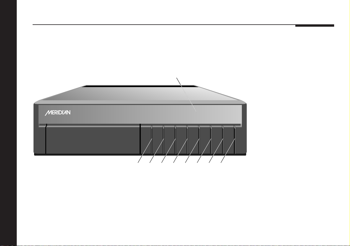
Front panel
BOOTHROYD STUART
551
Integrated Amplifier
Display
CD65
Source Display VCopy Spkrs Mute A Off
2345678
1
1 Source
Selects the source.
2 Copy
Copies a selected source
to the tape output.
3 Spkrs
Mutes the power amplifier.
4 Mute
Mutes the sound.
5 Display
Blanks the display.
6 V (Decrease)
Decreases the volume.
7 A (Increase)
Increases the volume.
8 Off
Switches to standby.
Using the integrated amplifier
10
Page 15

Selecting a source
During normal use the integrated amplifier should be left in the
standby state. This uses a negligible amount of electricity, but
ensures that the components of the integrated amplifier operate
at maximum efficiency from the moment you start.
If you are not going to use the integrated amplifier for a period of
several days you should switch the unit completely off, at the
back panel, and disconnect it from the AC power supply.
To switch on from standby
● Press Source (front panel), or select a source by pressing the
appropriate source key on the remote: eg CD.
If the 551 Integrated Amplifier is part of a Meridian system, it will
automatically switch on any other unit in the system, such as the
CD player.
To select a source
● Press Source (front panel) until the display shows the source
you require, or press the appropriate source key on the
remote: eg CD.
The display shows the source, and volume setting.
For example, if you select the
CD input the display will show:
By default, the following six sources are available:
Source Label Input
CD CD A2
Radio RD A3
LP LP A1
TV TV A5
Tape1 T1 A4
Tape2 T2 A6
CD65
To switch to standby
● Press Off on the front panel or the remote.
The display will show:
If you have other Meridian 500 Series equipment connected to
the integrated amplifier, these units will also switch to standby.
.
Using the integrated amplifier
11
Page 16

Adjusting the volume
The 551 Integrated Amplifier allows you to adjust the volume in
precise steps of 1dB, where 9dB is equivalent to doubling the
loudness.
The current volume setting is displayed in dB on the front panel
display, and can be varied in the range 1 – 99dB. When you first
switch on the integrated amplifier the volume is set to 65, which
is similar to the midway position of the rotary volume control on
a conventional preamplifier.
You can also mute the sound, or mute just the loudspeakers for
headphone listening.
To change the volume
● Press A or V (front panel), or the red A or V keys on the
remote.
As you adjust the volume setting the display will show the
current volume level.
For example:
Using the integrated amplifier
CD55
To mute the sound
● Press Mute.
The display will show:
Mute
To restore the sound
● Press Mute again.
Alternatively the sound will be restored if you adjust the volume.
To mute the loudspeakers
● Press Spkrs (front panel only).
The display will show:
Off
To restore the loudspeakers
● Press Spkrs again (front panel only).
12
Page 17
Changing the display and balance
To change the display
● Press Display.
Each time you press Display the display will step between the following options:
Display option Example
Source and volume.
This is the usual display.
Source only (full label).
Blank.
RD65
Rad
To change the balance
You can adjust the sound balance on the 551 Integrated
Amplifier using the following procedure.
Note: The balance can only be adjusted with the remote.
● Press < (remote) to move the sound to the left.
The display will show the number
of dBs added to the left channel:
● Press > (remote) to move the sound to the right.
The display will show the number
of dBs added to the right channel:
● Press V (remote) to centre the balance.
The display will show:
≤1
9≥
≤O≥
Using the integrated amplifier
13
Page 18

Recording a source
The 551 Integrated Amplifier allows you to copy any one of the
standard sources to the tape outputs, independently of the
source you are listening to.
To copy a source to the tape output
● Press Copy.
Each time you press Copy the integrated amplifier will step
between the following options:
Display Option
CSrc
CAtt
C CD
C RD
Copy Source. The current source is
fed to the tape output.
Copy Attenuate. The tape output is
muted.
Copies the first source to the tape
output.
Steps through each source in turn,
etc.
For example, to record a radio broadcast
press Copy until the display shows:
You can now listen to a CD, by selecting the CD source, without
affecting the recording.
C RD
Using the integrated amplifier
14
Page 19

Customising the integrated amplifier
This chapter explains how to customise the 551 Integrated Amplifier to
your preferred configuration.
The simplest way of configuring the integrated amplifier is to choose one
of the standard settings, which are designed to cater for the six most
common configurations of sources and inputs.
Alternatively, you can configure each source individually to suit the other
equipment in your system. You can choose the label used for each source,
and balance the input sensitivities so that the sound level remains the
same when you switch between sources.
Finally, the 551 Integrated Amplifier provides several settings that you can
alter to optimise the way in which it works with the other equipment in
your system.
Page 20

Choosing standard settings
The 551 Integrated Amplifier provides six alternative standard
settings, called Types, which configure all aspects of the
integrated amplifier into the six most commonly needed
configurations.
Choosing one of the six standard settings overrides any other
configuration you may have performed, and so can be used to
reset the configuration of the integrated amplifier.
By default, the integrated amplifier is supplied set to Type 1.
If you have a system containing only Meridian 500 Series units
then you should choose one of Types 5, 1, 4, or 3. These give
progressively larger numbers of inputs, as shown in the table
opposite.
If your system includes any Meridian 600 or 200 Series units you
should choose Type 2 or Type 6. For more information see To
connect to Meridian 600 or 200 Series equipment, page 30.
To select a standard setting
● Turn off the integrated amplifier, using the power switch on
the back panel.
● Turn on the power again while holding down the Off key on
the front panel.
The display will show:
It will then show:
VV
● Press
For example, to select Type 3
the display shows:
● Turn off the integrated amplifier using the power switch on the
back panel.
● Turn on again to use the standard settings you have selected.
AA
V or
A to change the type number.
VV
AA
Type
Ty 1
Ty 3
Customising the integrated amplifier
16
Page 21

Standard settings
The following table shows the options configured by the six standard Type settings on the 551 Integrated Amplifier:
Type
5143 Source Label Input Gain Comms
●●●● CD CD A2 0dB 1
●●●● Radio RD A3 2dB 2
●●●● LP LP A1 2dB –
●●● TV TV A5 8dB –
●●●● Tape1 T1 A4 2dB –
●●● Tape2 T2 A6 2dB –
● CDR CR A2 0dB –
● Cable Cb A5 8dB –
Customising the integrated amplifier
●● Text TX
●● VCR1 V1 A6 8dB –
● VCR2 V2 A4 8dB –
● LD LD A1 0dB –
= n/a –
= Last valid input, displayed as LV.
Types 2 and 6 have the same source configuration as Type 1.
17
Page 22

Configuring the sources
When the integrated amplifier is set to one of the standard
settings the twelve source selection keys on the remote select
the standard labels and inputs, as shown in the table on
page 17.
If the configuration you want is not catered for by one of the
standard settings, you can configure each source individually.
The 551 Integrated Amplifier provides 12 sources corresponding
to the 12 source selection keys on the remote:
CD, Radio, LP, TV, Tape1, Tape2, CDR, Cable, Text, VCR1,
VCR2, and LD.
For each source you can configure:
❍The label used for it on the front panel display, from 45
alternative labels.
❍The audio input it selects.
❍The comms type and address, to identify other Meridian 500
Series equipment.
The procedure for doing this is as follows.
Customising the integrated amplifier
To configure a source
● Turn off the integrated amplifier, using the power switch on
the back panel.
● Turn on the power again while holding down the Display key
on the front panel.
The display will show:
● Press Source until the left-hand pair of characters identifies
the source you want to configure.
For example, to configure the CD
source the display initially shows:
>>
● Press Copy (front panel), or
between options.
The right-hand pair of characters shows the current value of the
option.
The options are summarised in the table shown opposite.
<<
> and
< (remote), to step
>>
<<
Conf
CDCD
18
Page 23
To change an option
● Press A or V to step between the alternative values for the
option.
When you have finished programming sources:
● Switch off at the back panel, and then switch on again to
restore normal operation.
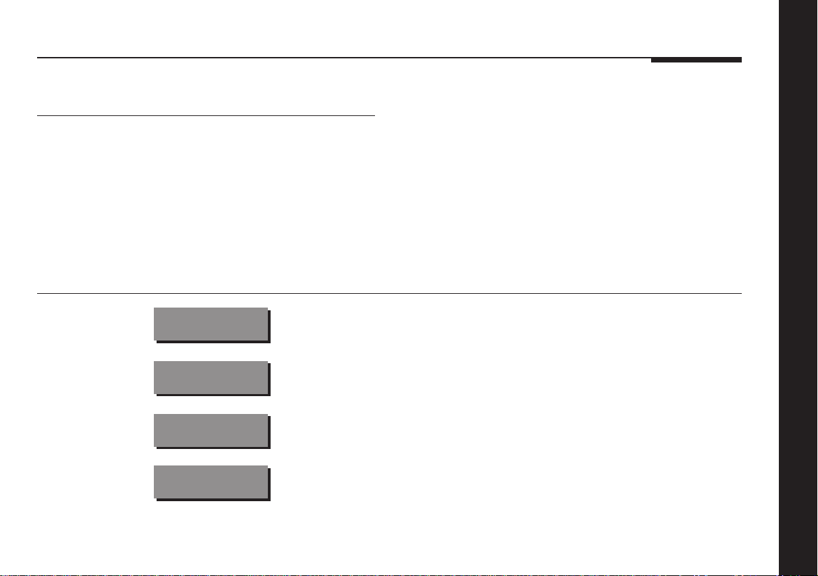
Option Initial value Alternative values Explanation
Customising the integrated amplifier
Label
Audio input
Comms type
Address
CDCD
CDA2
CD1C
CD1A
CD, RD, LP, etc. See page 20.
A1 – A6, or LV. Choose A1 to A6 to specify the input, or LV to use
the last valid input.
1C – 8C, or NC. Choose 1C for a Meridian CD player, 2C for a
Meridian FM Tuner, or NC otherwise.
1A – 8A. Allows you to have up to eight of each source type.
19
Page 24

Examples of configuring the sources
The following examples illustrate how you can configure the
source options to your own requirements.
To change a source label
● Display the source you want to configure, together with its
current label, as described in the previous sections.
For example, to configure the
Radio source label choose:
● Press A or V to step between the alternative labels.
For example, to use the label FM
for the Radio source set it to:
Over 50 alternative labels are provided to allow you to choose
the most appropriate ones for your sources. Selecting None
turns off the source.
RDRD
RDFM
To change the audio input for a
source
● Display the source you want to configure, together with the
current audio input, as described in the previous sections.
For example, to configure
the CD audio input choose:
● Press V or A to choose the audio input.
For example, if you want to use
input A3 for the CD set it to:
CDA2
CDA3
Customising the integrated amplifier
20
Page 25

To set up a system with two CD
players
● Configure the source you are going to use for the first CD
player.
For example: Source CD, Label C1, Audio input A2, Comms
type 1C, Address 1A.
● Configure the source you are going to use for a second CD
player, with a different address.
For example: Source CDR, Label C2. Audio input A3, Comms
type 1C, Address 2A.
The remote will now automatically control whichever of the CD
players you have selected with the CD or CDR source keys.
Customising the integrated amplifier
21
Page 26

Programming levels
The 551 Integrated Amplifier allows you to program the level of
each source independently, to suit your other equipment, so that
when you switch between sources the volume stays the same.
When you are programming levels the integrated amplifier
operates as a preamplifier with a fixed volume setting equivalent
to 65. This level is chosen to be comfortably loud on average
sources. You can switch between sources and adjust the
relevant input levels to achieve the setting you want.
You can increase the sensitivity of any source by up to 15 steps
of 1dB. The loudest source, usually CD, should therefore be
chosen as the reference.
To balance input levels
● Turn off the integrated amplifier, using the power switch on
the back panel.
● Turn on the power again while holding down the Mute key on
the front panel.
The display will show:
● Release the Mute key.
The display will show the
normal standby condition:
● Select the source that sounds loudest and make it your
reference.
● Switch to another source in the usual way.
Gain
.
Customising the integrated amplifier
22
Page 27

● Use the A and V keys to change the sensitivity.
For example, the display will show:
12dB
If you know the output level of your sources you can probably
set the gains by calculation. The following table shows the
correspondence between the gain and sensitivity on the
standard audio inputs and on the LP inputs:
● Switch between the source you are changing and the
reference source until they sound equally loud.
● Repeat the procedure for your other sources.
● When you have finished programming levels, switch the
power off and on again to restore the integrated amplifier to
normal operation.
Gain A2 – A6 LP MM LP MC
0dB 150mV 3mV 210µV
3dB 110mV 2.2mV 150µV
6dB 75mV 1.5mV 110µV
9dB 54mV 1.1mV 75µV
12dB 38mV 750µV54µV
15dB 27mV 550µV38µV
Customising the integrated amplifier
23
Page 28
Specifying information about your system
In addition to configuring the sources, and programming their
levels, you can configure many other aspects of the operation of
the 551 Integrated Amplifier to suit the way your system is set
up, and the way in which you want to use it.
Note that these settings are configured automatically to
appropriate values when you choose one of the standard Type
settings, and you should not normally need to alter them; see
Choosing standard settings, page 16.
To configure the integrated amplifier
● Turn off the integrated amplifier, using the power switch on
the back panel.
● Turn on the power again while holding down the Display key
on the front panel.
The display will show:
It will then show the first
configuration option:
Customising the integrated amplifier
24
● Press Copy to move between the options.
● Press A or V to change the value of the current option.
Conf
5OO
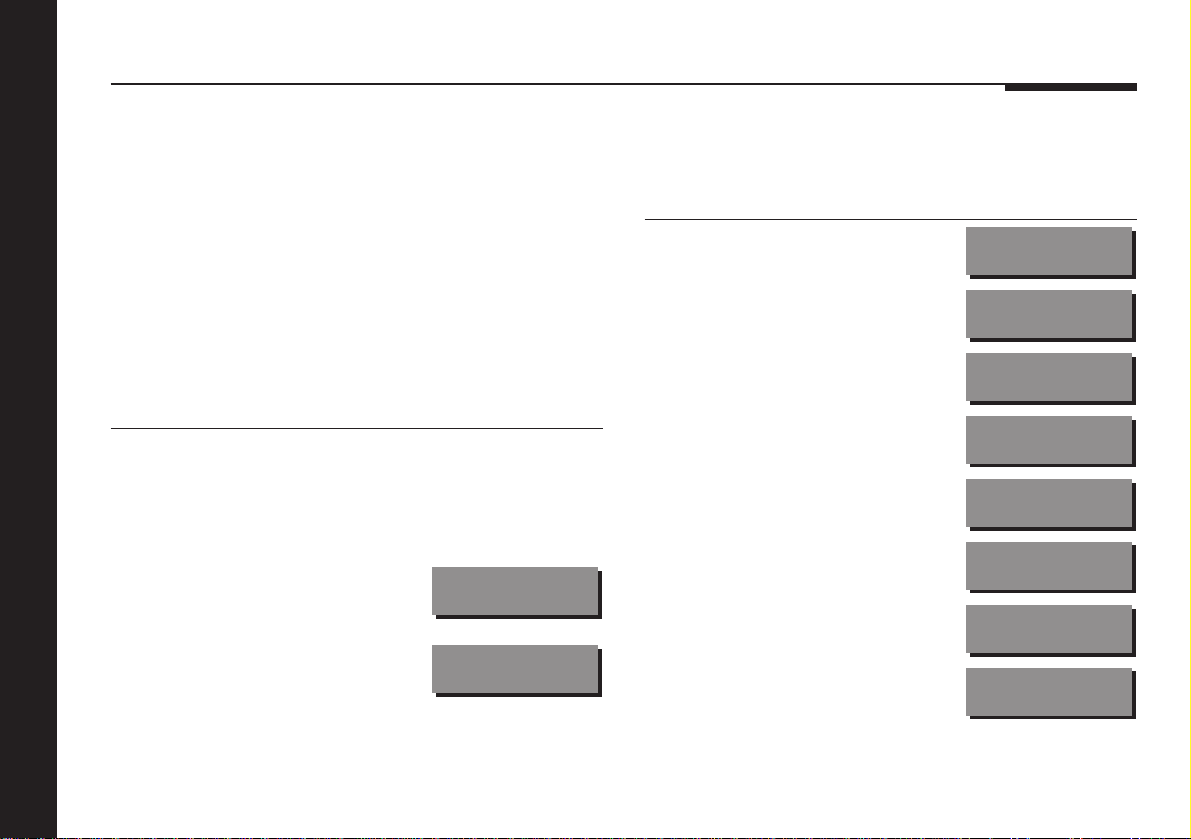
The following table shows the options you can configure:
Option Initial Value
Communications mode (500 or 200)
Controller mode (Auto, Con, or NCon)
System address (1–8)
Product address (1–8)
Volume control (Vout or Fout)
Volume mode (VolM or VolS)
Menu mode (N, 1, or 2)
200 Series CD player (N or Y)
5OO
Auto
SA=1
PA=1
Vout
VolM
≤≥N
CD?N
Page 29

Setting up the integrated amplifier
This chapter explains how to install the 551 Integrated Amplifier. It
describes what you should find when you unpack the integrated amplifier,
how you should connect it to your other audio equipment, and the siting
constraints.
You should not make any connections to the integrated amplifier or to any
other component in your system whilst the AC power supply is connected
and switched on.
Page 30

Unpacking
The 551 Integrated Amplifier comes in a box containing the
following components:
❍551 Integrated Amplifier.
❍1 power cord.
❍1 500 Series communications lead.
❍This manual.
You are advised to retain the packing in case you need to
transport the unit.
To position the integrated amplifier
During normal operation the heatsinks, ie the fins at each end of
the case, may become quite hot. The integrated amplifier should
therefore be positioned to allow a free flow of air around the fins.
Do not place the integrated amplifier:
❍In direct sunlight.
❍Near heat sources, eg a radiator.
❍Stacked with any other audio products, as the heat it
generates may damage the other products.
Before connecting power
Before installation you should ensure that your integrated
amplifier is set to the correct voltage for your local AC supply. If
it is not, do not try to install the unit, and contact your dealer.
Do not make connections, or insert or remove plugs, while
the unit is connected to the supply and switched on, as the
transients generated could damage the loudspeakers.
Radio interference
FCC Warning: This equipment generates and can radiate radio
frequency energy and if not installed and used correctly in accordance
with our instructions may cause interference to radio communications
or radio and television reception. It has been type-tested and
complies with the limits set out in Subpart J, Part 15 of FCC rules for a
Class B computing device. These limits are intended to provide
reasonable protection against such interference in home installations.
EEC: This product has been designed to comply with the limits
set out in EN55013 and EN55020C.
Setting up the integrated amplifier
26
Page 31
Connecting the integrated amplifier
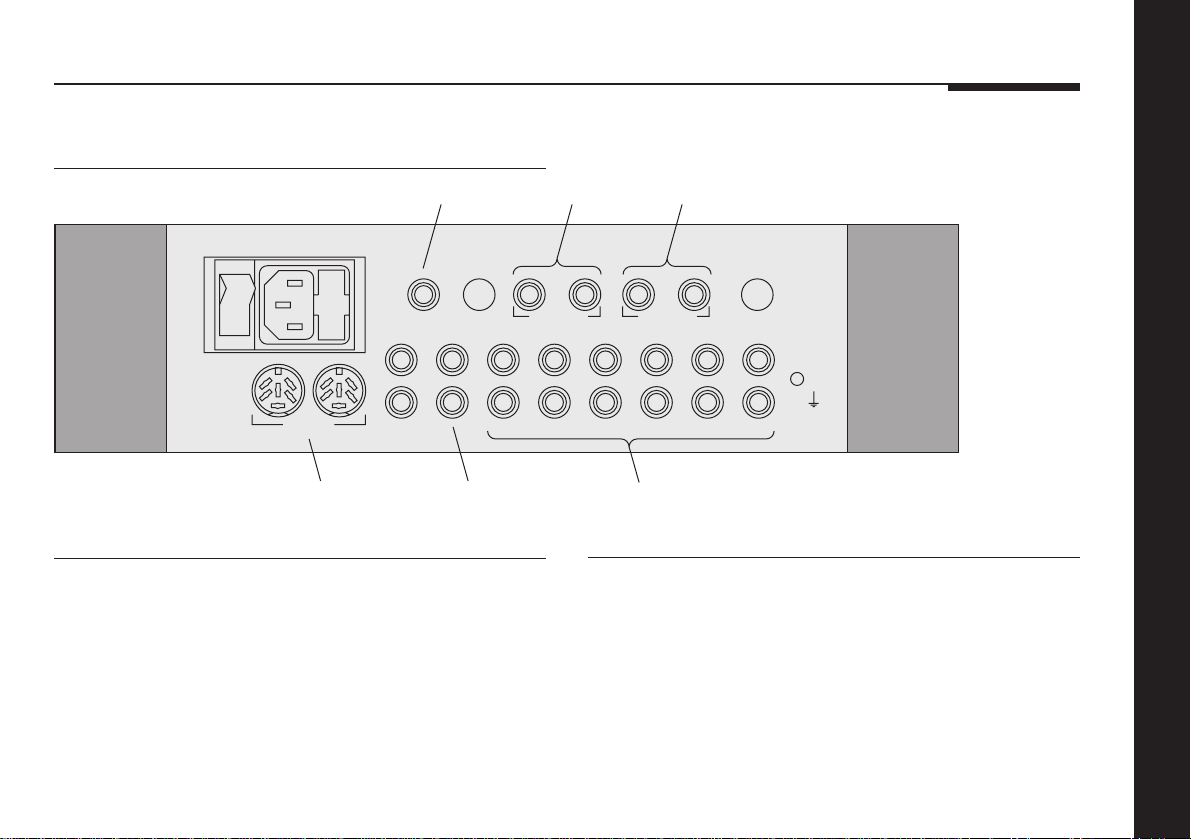
Back panel
Headphones
OFF
Headphones
ON
COMM
Pre-amp Out Tape 2 TV Tape 1 Radio CD LP
Comms
connections
Tape Out
Fuse
3.15A FST
Tape
outputs
Audio connections
The audio connections should be made using high-quality
screened cable, taking care to connect the left and right
channels correctly.
The following table gives details of the six audio inputs:
Output (R) Output (L)
Right Output
Min 8Ω Load
A6 A5 A4 A3 A2 A1
Left Output
Min 8Ω Load
3.15A FST
Audio
inputs
Use this input To connect to this
A1 A turntable pickup with optional
A2 to A6 Other audio sources.
Fuse
L
TECH
R
MM/MC module.
Setting up the integrated amplifier
27
Page 32
The following table gives details of the audio outputs:
Use this output To connect to this
Right/Left Output Loudspeakers of 4Ω to 15Ω, using
either banana plug or bare wire
connections.
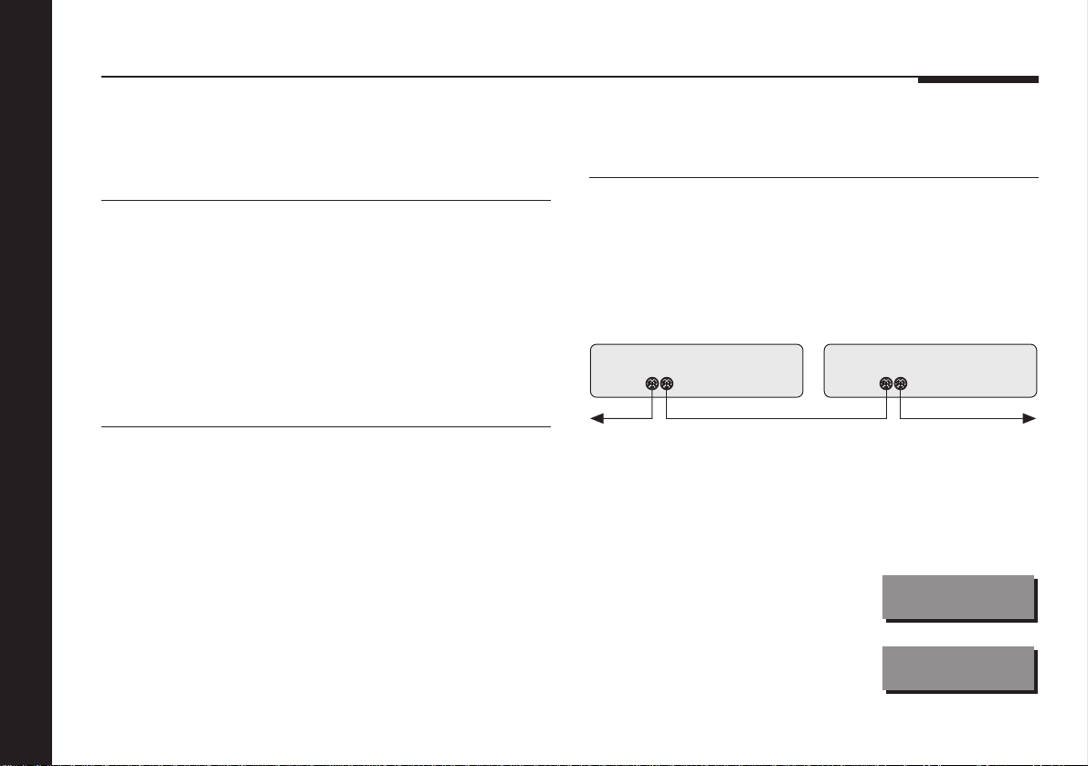
To connect to other Meridian 500
Series equipment
● Connect one of the COMMS sockets on the back panel of the
integrated amplifier to one of the COMMS socket on another
500 Series unit, using the 500 comms lead.
Pre-amp Out An additional power amplifier or active
Tape Out Tape recorder output.
To connect to a tape recorder
● Connect the analogue output from the tape recorder to the
Tape 1 input on the integrated amplifier (or another input if
you prefer).
● Connect the Tape Out from the integrated amplifier to the
analogue input on the tape recorder.
Setting up the integrated amplifier
28
loudspeakers.
The sequence in which you connect the units is not important.
COMMS COMMS
Then configure the units with the following automatic setup
procedure:
● Switch all the units to standby.
● Press Clear on the remote.
Each unit will display:
One unit will then be designated
as the controller, and display:
Auto
Con
Page 33
This is the unit that will respond to the remote.
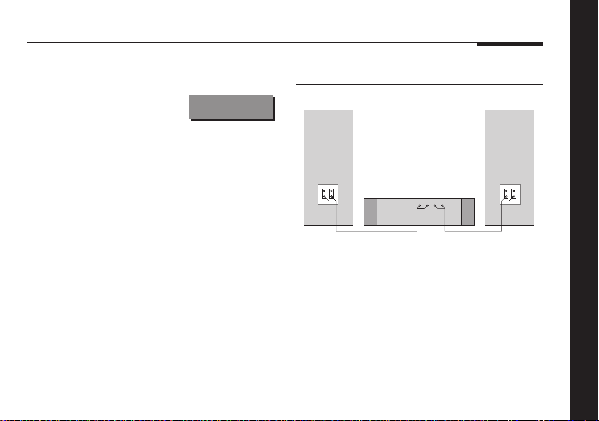
To connect to A500 Loudspeakers
All the other units will be configured
as non-controllers, and display:
Your system is now set up and ready for use.
● If, for any reason, the automatic setup does not give the
configuration you want, restore the default operation by
selecting Type 1 as described in To connect to Meridian 600
or 200 Series equipment, page 30.
● If you want to change the automatic setup configuration refer
to the Meridian 500 Series User Guide.
Note: Do not, under any circumstances, connect any equipment
other than Meridian 500, 600, or 200 Series to the socket
marked COMMS on the back of the integrated amplifier.
NCon
A500 LoudspeakerA500 Loudspeaker
551 Integrated Amplifier
Setting up the integrated amplifier
● Use the links provided to bridge the BASS/MID and TWEETER
terminals on the back of each loudspeaker.
● Connect one of each pair of the red and black terminals on
the back panel of the 551 Integrated Amplifier to the red and
black terminals on the A500 Loudspeakers.
29
Page 34

To connect to Meridian 600 or 200
Series equipment
● Switch the power off and on again to restore the integrated
amplifier to normal operation.
If your system includes any Meridian 600 or 200 Series units,
with 600 COMMS or 200 COMMS sockets, you should set all
the 500 Series units to 200 COMMS operation using the
following procedure:
● Turn off the integrated amplifier, using the power switch on
the back panel.
● Turn on the power again while holding down the Off key on
the front panel.
The display will show
the current Type setting:
● Press A or V on the front panel to change the Type setting.
If your system includes a Meridian CD player select Type 2;
otherwise select Type 6.
For example, if you select
Setting up the integrated amplifier
30
Type 2 the display will show:
● To return to 500 COMMS operation repeat the above
procedure, and select Type 1, 3, 4, or 5. For more information
see Choosing standard settings, page 16.
Ty 1
Ty 2
Page 35

Troubleshooting
This section describes problems you may encounter when using
the integrated amplifier, and includes suggested solutions.
If these suggestions fail to cure the problem, please contact
your Meridian dealer for further assistance.
No lights are displayed when
switching on
❍Check that your AC power supply is connected correctly.
❍Check that the ON OFF switch on the back panel
is in the ON position.
❍Check that the fuse on the integrated amplifier back panel and
the fuse in the unit’s power plug have not blown; see To
change the mains fuse, page 33.
The sound has cut out
The 551 Integrated Amplifier includes output fuses, which
protect the output if the connections are accidentally shorted.
❍Check the output fuses.
The sound has cut out and the display
shows DC
This indicates that the power amplifier has turned off due to a
DC offset on the output.
❍Unplug the source.
If this restores normal operation check the source. Otherwise
there may be a fault with the integrated amplifier, and you
should consult your dealer.
The sound has cut out and the display
shows Hot
This indicates that the power amplifier has turned off due to
overheating.
❍Allow the integrated amplifier to cool down.
If the problem continues to occur there may be a fault with the
integrated amplifier, and you should consult your dealer.
Setting up the integrated amplifier
❍If necessary, replace the fuse with one of the same rating.
31
Page 36

Communication is not working
between the 551 Integrated Amplifier
and other Meridian products
There is hum on other inputs
❍Check your other equipment.
❍Check that all products are interconnected using the correct
comms leads.
❍If the installation includes 200 Series or 600 Series units,
check that all 500 Series units are set to 200 mode.
There is hum on the LP input
The LP input is the most sensitive input on the integrated
amplifier.
❍Check that the tone arm is connected to the technical ground
of the integrated amplifier.
❍Check that the tone arm is connected to the power ground in
the turntable.
❍If you are using a magnetic pickup, check that there is not
another piece of equipment too near to the turntable or the
left-hand side of the integrated amplifier. If so, re-position the
Setting up the integrated amplifier
32
equipment to cure the problem.
❍If you are unable to cure the problem consult your dealer.
There is interference on the radio and/
or television when the integrated
amplifier is switched on
Before following the steps below, ensure all units are switched
off.
If this equipment does cause or suffer from interference to/from
radio or television reception then the following measures should
be tried:
❍Reorient the receiving aerial (or antenna) or route the antenna
cable of the receiver as far as possible from the 551
Integrated Amplifier and its cabling.
❍Ensure that the receiver uses well-screened antenna cable.
❍Relocate the receiver with respect to the integrated amplifier.
❍Connect the receiver and this product to different AC outlets.
Page 37

Maintenance
Cleaning
When cleaning the integrated amplifier bear in mind that the
front of the integrated amplifier is plastic, and the display panel
and lid are glass.
Disconnect the power cord before cleaning the unit.
Note: Do not use abrasive cleaners on any part of the integrated
amplifier.
To clean the case, display panel, and
keypad
● Use a slightly damp cloth.
Ensure that no water is allowed to get inside the case, and do
not reconnect the power until you are certain that the integrated
amplifier is completely dry.
To clean the audio connections
The audio sockets on the back of the integrated amplifier are
gold-plated and need no cleaning if gold-plated phono plugs are
used. Otherwise, it is recommended that you unplug and
reconnect the plugs at least once a year. A proprietary contact
cleaner can be used to some advantage.
To change the mains fuse
Fuse
Spare
● Remove the mains connector, and pull out the drawer next to
the power input to access the fuses.
Before replacing a blown fuse, if possible ascertain the cause of
the failure.
Setting up the integrated amplifier
The fuse drawer includes a spare fuse. This should be replaced
by one of the same rating.
33
Page 38

Service and guarantee
Service
The Meridian 500 Series of hi-fi components have been carefully
designed to give years of untroubled service. There are no userserviceable parts inside the case, nor do the units require any
form of maintenance.
In the unlikely event that your integrated amplifier fails to
function correctly, it should be returned, in its original
packaging, to your Meridian dealer.
In case of difficulty within the UK or USA please contact the
appropriate sales and service address shown on page ii.
In case of difficulty outside the UK or USA, contact the importing
agent for the territory. A list of Meridian agents abroad is
available from Meridian Audio.
No responsibility can be accepted for the integrated amplifier
whilst in transit to the factory or an agent, and customers are
therefore advised to insure the unit.
When seeking service under guarantee, proof of the date of
Setting up the integrated amplifier
34
purchase will be required.
Guarantee
The 551 Integrated Amplifier is guaranteed against defects in
material and workmanship for 2 years from the date of purchase.
The guarantee is void if the 551 Integrated Amplifier has been
subject to misuse, accident, or negligence, or has been
tampered with or modified in any way without the written
authorisation of Meridian Audio Limited. Note that connecting
anything other than the correct network lead to the COMMS
sockets may cause damage to the 551 Integrated Amplifier
which will not be covered by this guarantee. Attempted servicing
by unauthorised people may also invalidate this guarantee.
Labour and carriage charges are not covered unless by local
agreement.
Outside the UK, local warranty liability is restricted to equipment
purchased within the territory. Our agents abroad are only under
contractual obligation to service under guarantee equipment
sold through them. They are entitled to make a non-refundable
charge for any service carried out on other equipment.
This guarantee does not limit your statutory rights within the
United Kingdom.
Page 39

Index
A
Accessories 7
Adjusting
balance 13
volume 12
B
Back panel 27
Balance
adjusting 13
centring 13
Balancing input levels 22
C
CD players, using two 21
Changing the display 13
Cleaning 33
the audio and video connections 33
the case 33
Components 26
Configuration options
200 Series CD player 24
communications mode 24
controller mode 24
menu mode 24
product address 24
system address 24
Configuration options (continued)
volume control 24
volume mode 24
Configuring sources 18
address 19
audio input 19
comms type 19
label 19
Configuring the integrated
amplifier 24
Connecting
to a tape recorder 28
to A500 Loudspeakers 29
to Meridian 500 Series
equipment 28
to Meridian 600 and 200 Series
equipment 30
Copy Attenuate option 14
Copy Source option 14
Copying a source 14
Customising the integrated
amplifier 15
D
DC display 31
Digital output 27, 28
Display 13
changing 13
F
Front panel controls 10
Fuse, replacing 33
G
Guarantee 34
H
Heat generated during
operation 26
Hot display 31
Hum problems 32
I
Inputs, audio 27
Installing 26
Introduction 1
L
Labels 20
Last valid input 17
Levels, programming 22
Loudspeakers, muting 12
M
Maintenance 33
MC phono module 7
Index
35
Page 40

36
Index
Meridian 500 Series 2
500 Compact Disc Transport 3, 4
501 Control Unit 3
502 Analogue Controller 4
504 Stereo FM Tuner 3
506 20-Bit CD Player 3
555 Stereo Power Amplifier 3
557 Stereo Power Amplifier 4
562 Digital Controller 3
562V Multimedia Controller 5
566 20-Bit Digital to Analogue
Converter 4
communications 2
Meridian 500 Series operation,
setting 28
Meridian 600 and 200 Series
operation, setting 30
Meridian A500 Loudspeakers 3, 4
Meridian D6000 Digital
Loudspeakers 5
Meridian DSP5000 Digital
Loudspeakers 3
Meridian System Remote 2
MM phono module 7
Muting the loudspeakers 12
Muting the sound 12
O
Outputs, audio 28
Overheating 26
P
Phono modules
MC 7
MM 7
Positioning 26
Programming levels 22
R
Radio interference 26
Record a radio broadcast 14
Recording a source 14
S
Service 34
Setting up the integrated
amplifier 25
for 500 Series operation 28
for 600 and 200 Series operation 30
Sound
muting 12
muting the loudspeakers 12
Sound (continued)
restoring 12
restoring the loudspeakers 12
Sound has cut out 31
Source labels 20
Sources
changing label 20
configuring 18
copying 14
default 11
programming levels 22
recording 14
selecting 11
Specification, 551 6
Standard settings, selecting 16
Standby mode 11
Switching on from standby 11
Switching to standby 11
T
Tape recorder, connecting to 28
Troubleshooting 31
Types 30
selecting 16
Page 41

U
Unpacking 26
Using the integrated amplifier 9
V
Volume
changing 12
display 12
muting 12
restoring 12
Index
37
 Loading...