

Page 1
SL-1
System options
System overview
Standard
21,51,61,71
- :;..‘,
-:
‘\
I
i\
.’
Page 2

SL-1
System options
21,51,61,71
System overview
Publication number: 553-3001-I 00
Document release: 1 .O
Document status: Standard
Date: January
29,199O
0
1990 Northern Telecom
All right reserved
System overview 553-3001-l 00
-.
.:.
.:
.’
Page 3

ii
Revision history
January
29,199O
Standard,
release
1.0
System overview 553-3001-100
‘: :.“‘I
\
j
Page 4
About this document
This document describes the features and services, hardware and software
architecture, and the family of products that comprise Meridian 1.
References
See the SL-I planning & engineering guide
-
Master index
-
System overview
-
Installation planning
-
System engineering
-
Power engineering
-
Sparesplanning
-
Equipment identification and ordering
(553-3001-000)
(553-3001-100)
(553-3001-120)
(553-3001-151)
(553-3001-152)
(553-3001-153)
iii
for
(553-3001-154)
See the list of
line
and trunk circuit descriptions in
the Master index
(553-3001-000) for specific references to lines and trunks.
See the SL-1 installation and maintenance guide
-
System installation procedures
-
Circuit pack installation and testing
-
Installation procedures for telephone sets
and attendant consoles
-
Extended systems installation
-
Disk drive upgrade procedures
(553-3001-215)
(553-3001-210)
(553-3001-211)
(553-3001-250)
(553-3001-251)
for
System overview 553-3001-100
Page 5
iv About this document
-
-
-
General maintenance information
Fault clearing
Hardware replacement
(553-3001-510)
(553-3001-520)
(553-3001-500)
See the SL-1 XII software guide
for an overview of software architecture,
procedures for software installation and management, and a detailed
description of all Xl 1 features and services. This information is contained
in two documents:
-
XII software management (553-3001-300)
-
XII features and services
See the
SL-1
XII input/output guide
(553-3001-305)
(553-3001-400) for a description of all
administration programs, maintenance programs, and system messages.
System overview 553-3001-100
,. ‘; -.
‘.’
_......
_ .
.
j,
Page 6

Contents
V
Meridian 1
The Meridian 1 commitment
Advanced features
System architecture
Meridian 1 modular architecture
Control
Switching
Peripherals
Software architecture
Firmware
Software
Office Data
Resident Programs
Non-Resident Programs
Hardware architecture
Common equipment
Network equipment
Peripheral Equipment
Power equipment
Product description
Universal Equipment Modules
CPU module (NT8D34)
CPU/Network module (NT6D39)
Network module (NT8D35)
Common/Peripheral Equipment module
Intelligent Peripheral Equipment module (NT8D37)
Peripheral Equipment module (NT8D13)
(NTSDll)
1
2
5
9
9
9
9
10
10
11
11
11
11
11
13
13
17
31
32
37
37
39
41
43
45
48
50
System overview 553-3001-100
c
Page 7

vi Contents
Remote Peripheral Equipment Carrier module (NT8D47)
InterGroup module (NT8D36AA)
Meridian Mail module (NT6D44)
Pedestal (NT8D27AB)
Top cap
Expansion kit (NT8D49)
Meridian 1 system options
Meridian 1 system option 21A
Meridian 1 system option 21
Meridian 1 system option 51
Meridian 1 System option 61
Meridian 1 system option 71
(NT7DOO)
List of terms
52
54
55
57
57
57
60
60
62
64
66
68
71
System overview 553-3001-l 00
Page 8

1
,:
/:; ::
! . .
Meridian
1
Introduction
Meridian 1 Communication Systems are a family of digital multiplex voice
and data switching systems built upon a foundation of state of the art digital
switching equipment and advanced software program control. Meridian 1
systems provide a wide range of sophisticated voice and data services for
both Private Branch Exchange (PBX) and Central Office (CO) applications
ranging in size from 30 to 60,000 ports.
A Meridian 1 Communication System is a single source solution to the
complex requirements of today’s business communications environment. In
a single, integrated system, it provides advanced voice features, local
network communications, and sophisticated information services. A
comprehensive open architecture ensures continual growth in capacity and
the capability to address the ongoing needs of business communications and
information management.
The foundation for Meridian 1 Communication Systems is a voice and data
circuit-switched digital sub-system. It is comprised of a central processing
unit, memory store, and a digital switching network that uses time division
multiplexing and pulse code modulation techniques. Peripheral interfaces
are used to connect a wide array of telephones, trunks, and terminals.
Meridian 1 Communication Systems systems are also designed to
accommodate the rapidly expanding requirements for data communications.
.~.,.
..‘
)I
Building upon the strength of the original SL-1 architecture, significant
system enhancements have been developed for data communications,
including:
area
System overview 553-3001-100
Page 9

2 Meridian 1
Meridian Modular Telephones, a family of digital telephones that
utilize standard twisted pair wiring and support a wide range of data
communications options.
Meridian 1 LANSTAR, a 2.56 Mbps local area network (LAN) for
Macintosh II and IBM PC compatible computers.
The Meridian 1 commitment
Northern Telecom is committed to meet the needs of our customers by
providing systems which guarantee:
Continuing product compatibility
A high degree of component and system reliability
Cost effective, modular packaging
Advanced administration and maintenance capabilities
Ease of installation
Cost effective system expansion and upgrade
Product compatibility
All new products are compatible with the installed base of systems and can
be installed alongside existing equipment. For network enhanced Meridian
SL-1 systems, the upgrade consists of adding X11 release 15 software with
a new CPU ROM pack, Superloop Network cards in existing network slots,
and one or more Intelligent Peripheral Equipment Modules. For non-
network/GE enhanced Meridian SL-1 systems, an upgrade package is also
available. For more information about extending existing systems, see
Extended systems installation
(553-3001-250).
In addition, Meridian 1 systems now utilize the DS-30 signalling method
used by other Northern Telecom switching products, providing a common
signalling scheme throughout the Meridian 1 family and allowing for
system growth beyond 10,000 ports without requiring a change in peripheral
equipment.
System overview 553-3001-l 00
.i
Page 10
System reliability
Meridian 1 systems are designed and built to meet the highest standards for
reliability, resulting in less downtime and increased system availability. In
most systems, critical system elements are duplicated to guarantee system
reliability. There are two identical Central Processing Unit (CPU) and
memory circuits in most system configurations, and both CPUs can access
both memory circuits. If one CPU or memory circuit fails, the system
automatically switches to the standby CPU or memory circuit without
disrupting call processing.
Modular equipment packaging
Meridian 1 hardware is housed in modular equipment cabinets that are
common to all system elements. These cabinets are called Universal
Equipment Modules (UEM). Each UEM has removable front and rear
covers with locking latches for easy access to its contents.
UEMs are stacked one on top of another to form a column. Each column
may contain up to four UEMs. Systems are comprised of one or more
columns. An Expansion Kit is provided to interconnect the columns in a
multi-column system for compliance with FCC standards for EMI/RFI. At
the base of each column of UEMs is the pedestal The pedestal houses
cooling fans, air filters, a power distribution assembly (including the circuit
breakers and power switches) and a System Monitor circuit. At the top of-
each column is a Top Cap assembly which consists of two air exhaust
grilles and a thermal sensor assembly.
Meridian 1 3
Advanced administration & maintenance
An important feature common to all Meridian 1 systems is an advanced
administration and maintenance system. Administration and maintenance
functions can be performed locally or at a remote location. These functions
include service change, reassignment of features, and additions or deletions
of equipment. Meridian 1 systems also provide an automatic in-line
conversion feature which significantly simplifies upgrades of Xl 1 software.
Reconfiguration of system data structures occurs during system reload.
A System Monitor circuit card controls and monitors the status of all power-
related hardware and functions, including column thermal status, power
supply operation, blower operation, power fail transfer, circuit breakers,
external rectifiers, batteries, and Uninterruptable Power Supply (UPS)
systems. The same system monitor is used for AC and DC powered
System overview X3-3001 -100
L.
,.
.’
Page 11

4 Meridian 1
systems. A System Monitor is installed in.the pedestal of each column.
The System Monitor located in the column containing CPU0 acts as the
master system monitor; monitors located in other columns act as slaves.
The master polls the slaves and reports their status to the CPU. The master
System Monitor is connected to the CPU by an RS232C port located on an
SD1
card. Slave System Monitors are connected to the master in a daisy
chain fashion with an 8-conductor RJ type connector.
System messages reported to the CPU by the System Monitor are output to
the system terminal. System messages include the following types of
information: status or fault indication, hardware type, column number,
module number and power supply unit number.
Maintenance and traffic messages are also output to the system terminal.
Maintenance messages indicate the results of diagnostic routines and alert
maintenance personnel to fault conditions. Traffic messages indicate the
load on different areas of the system and the associated grade of service.,
Meridian 1 systems feature an advanced background diagnostic program
which reports system status and identifies detected faults. The program
automatically restarts where it stopped, following an interruption.
Diagnostic routines may also be initiated by maintenance personnel as
required.
_
A new series of circuit cards contain microprocessors which offload
processing functions previously performed by the CPU. The on-board
microprocessors significantly increase circuit card and system diagnostic
capabilities, resulting in improved maintainability. Where possible,
hardware switch selection has been replaced with software-controlled
selection of circuit card options. The on-board microprocessors also allow
for circuit card parameters to be changed without requiring hardware
revisions. Parameters are stored on the system disk drive unit, and are
downloaded to the circuit card at system reload or upon user command.
The new cards also make use of on-board intelligence by reporting their
product code, serial number, release number and manufacture location,
assisting maintenance and inventory control.
System overview 553-3001-100
.4
.
Page 12
Meridian 1 5
Ease
of installation
Every Meridian 1 system is shipped from the factory assembled and
equipped to order. Installation effort is reduced to unpacking and
positioning equipment, plugging in connectorized cables, ‘and adding
customer-specific programming where required.
Ease of expansion
The modular packaging scheme employed by the Meridian 1 family of
products accommodates growth by permitting easy expansion. System
expansion simply requires adding one or more UEMs. The modular
packaging scheme also provides for low cost, easy expansion from one
system type to another. For example, the card cage assembly of a UEM
containing CPU equipment for a small system may be removed and
replaced with the CPU card cage assembly designed for larger systems.
addition, peripheral equipment, which is the bulk of the system investment,
is common to all system types and may be retained when
Advanced features
By providing service capabilities defined by software, which can be
expanded as needs evolve, Meridian 1 systems offer advanced features and
capabilities in an economical, flexible, and maintainable form. In addition.to a wide range of standard voice and data services, Meridian 1 systems also
provide a number of sophisticated communications services and features,
including:
In
expandi&
ACD
Y
-
Automatic Call Distribution (ACD)
-
Electronic Switched Network (ESN)
-
Call Detail Recording (CDR)
-
Integrated Services Digital Network (ISDN)
-
Meridian Mail Voice Messaging
Automatic Call Distribution (ACD) is used when a large volume of
incoming calls must be answered by a group of telephones allocated for this
purpose. Incoming calls are served on a first-in, first-out basis and are
distributed among the available telephones. For more information on ACD,
refer to Northern Telecom Publication
features description
(553-2671-100).
Automatic Call Distribution Basic
System overview 553-3001-l 00
..:
Page 13
6 Meridian
1
ESN
CDR
The Electronic Switched Network (ESN) group of features supports voice
and circuit-switched voiceband data telecommunications for multiplelocation customer applications. ESN applications range from a single
network node (combined PBX and network switching system) to a widely-
dispersed network with up to 256 locations. For more information about
ESN, refer to the ESN Feature Document 6400-886 and to the following
Northern Telecom Publications:
-
ESN: 308-3001-100
-
BARSmARS: 553-2751-100,553-2751-101
-
CDP: 553-2751-102
Call Detail Recording (CDR) is a software package that gathers call
processing data and produces call records used for accounting and
administrative purposes. Call records provide information about the call,
such as the time and date the call was placed, the identity of the caller, and
the digits dialed. CDR is compatible with all Meridian 1 software generics.
For more information,
see Call Detail Recording general description
(553-2631-100).
ISDN
Integrated Services Digital Network (ISDN) is an international specification
of standards for digital communications. ISDN provides standard digital
interfaces between telephones, terminals, and telecommunication networks.
ISDN services are distinguished by two types of access: Primary Rate
Access (PRA) and Basic Rate Access (BRA). For more information on
PRA,
see ISDN Primary Rate Access product description
Meridian Mail Voice Messaging
Meridian Mail is a comprehensive electronic voice processing system
designed and developed to increase any organization’s productivity by
enhancing telecommunications activities. Meridian Mail provides a wide
array of sophisticated features, including: telephone call answering, voice
messaging, automated attendant service, call routing, information mailbox,
and interactive voice response applications.
System overview 553-3001-I 00
c
(553-2901-100).
L’..%‘.
,:.. :.:
::
55
.:_ $
i
:.
..:
.
..I
Page 14

Meridian 1 7
Meridian Mail voice messaging eliminates telephone tag and wasted calls
by allowing detailed messages to be exchanged when parties are unavailable
or busy.
Guided by easy to follow prompts, a user can leave messages for
others, retrieve messages, forward messages, and respond to messages with
the touch of a single button.
i
.
II:.,-;.
.: -.
.
“T’.’ :
‘Z..,
...:
-
System overview 553-3001-l 00
Page 15

8 Meridian 1
,
. . .
_ .’
h
r-
-*
System overview 553-3001-100
+
.
.
Page 16

System architecture
9
Meridian
Control
Switching
1 modular architecture
An important characteristic of Meridian 1 systems is a modular system
architecture. It utilizes an efficient and flexible approach, employing
modular construction in all areas of hardware and software, and state-of-the-
art commercial and custom components. The result is a system which is
highly flexible in terms of operational, maintenance, and administrative
characteristics. As demands dictate, any module may be enhanced,
singularly or in combination with other modules. Each system is organized
around three functional areas: Control, Switching, and Peripherals.
The Control complex provides the sequences required by the system to
process voice and data call connections, monitor call activity, and perform
system administration, maintenance, and testing. It is composed of two
elements: the central processing unit (CPU) which directs lower level
subsystems in the hierarchy, and the system memory which stores the
operating programs.
The switching function is performed by the network equipment, which
interconnects terminal devices for communication with each other. The
network architecture is based on the concept of a digital multiplexed loop.
A loop is a bidirectional path between Network and terminal device which
transmits voice, data and signalling information.
System overview 553-3001-100
.d
Page 17
10 System architecture
Peripherals
Peripheral equipment provides the analog and digital interfaces for all
peripheral devices, and performs analog to digital conversion of all input
signals before switching is performed by the Network. Additionally,
Peripheral equipment circuits provide the supervisory and transmission
functions needed for trunks connected to the external telecommunications
network.
Meridian 1 systems use a star topology for connecting peripheral devices to
the switching equipment, an approach which permits uniform distributed
wiring methods. This approach provides significant benefits in the area of
administration, installation, maintenance and reliability.
Figure 1
Meridian 1 modular architecture
Control
Software architecture
The adaptability of software control provides a complete array of services
and features tailored to meet changing requirements.
Call processing, maintenance and administration of Meridian 1 systems are
controlled by software programs stored either as firmware programs, as
software programs resident in system memory, or as non-resident programs
on disk. The information which describes system configuration and
associated peripheral equipment is termed office data. This data resides in
the system memory and on disk.
Switching
Network
Circuits
Peripherals
-yjgjJ
System overview 553-3001-I 00
. .
Page 18

.:;
::
j
.,..“.
_....~
,‘;-T.>g ->yy
I
:
;-“‘:
,
.
..~
. .
,’
:
Firmware
These are fundamental programs consisting of hard-wired logic instructions
stored in Programmable Read Only Memory (PROM) which manipulate
data in the central processor and control input/output operations, error
diagnostic and recovery routines.
Software
Software programs consist of instruction sequences that control call
processing, peripheral equipment, administration and maintenance
functions. These sequences are interpreted by the fiiware programs into
machine instructions. Several generic software programs with optional
feature packages are available to satisfy varying requirements.
Office Data
The office data describes the characteristics of the system in terms of
configuration and call dependent information such as features and services.
Office data is arranged into blocks defining peripheral equipment, system
configuration and transient data. These data blocks permit configuration of
Meridian 1 systems to specific customer needs.
Resident Programs
Resident Programs are programs always available in memory during system
operation. Firmware programs control other resident programs and provide
all CPU arithmetic operations. The other resident programs are those which
are automatically loaded into the system memory from the disk drive at
system power-up. Once loaded, these programs remain in memory.
System architecture
I I
Non-Resident Programs
Non-Resident Programs are the overlay programs stored on disk which are
loaded into the “overlay area” of system memory when required to perform
specific tasks. Only one overlay program may be loaded at a time and is
removed from the overlay area when no longer required. Overlay programs
can be loaded automatically, under program control, or manually, via an
administrative terminal.
Once the user has logged into the system, commands for specific overlay
programs are processed by the overlay loader program. When loaded, the
overlay program assumes control. Only one administrative terminal can
input into the overlay arca at a time. More than one device, however, can
System overview 553-3001-l 00
Page 19

12 System architecture
receive output simultaneously. A terminal may be configured as an input
only or
Overlay programs provide the system interface for maintenance, service
change, and traffic measurement. Each overlay program is independent and
has its own specific set of commands and formats. Overlay programs may
be run concurrently with normal call processing without interfering with
system traffic. There are five main categories of overlay programs:
Service Change and Print Routines
Service changes do not generally require hardware intervention. Instead,
the service administration programs are used to create or modify all aspects
of the system from individual feature key assignments to complete system
configurations. There are also programs and print routines for retrieving the
data from the system to check the status of office data assignments.
Maintenance Diagnostics
These programs are the primary instruments for maintenance purposes.
Individual programs are used for automatically or manually testing the CE
and PE. The programs may be loaded into the overlay area at the request of
maintenance personnel, or as part of a daily maintenance routine
automatically initiated by the system at a specified time. In addition,
background and signaling diagnostic routines can occupy the overlay area
when it is not in use.
output
only device.
-.-
Traffic
All systems are equipped with traffic data accumulation programs. There is
also a resident traffic print program which examines the schedules, transfers
data from accumulating to holding registers in accordance with schedules,
and prints the traffic data. In addition, there is a traffic overlay program
which is used to query and modify schedules, options, and thresholds.
Equipment Data Dump
After making service changes, the changes must be transferred to disk in
order to save them. When the equipment data dump program is invoked, all
the office data in the read/write memory is written to the system disk. The
data dump program is also used to install a new generic version or issue and
capture protected data store information which may be changed by the user,
such as speed call lists. The program may be invoked automatically during
System overview 553-3001-l 00
Page 20

a midnight routine or on a conditional basis (i. e. , data dump only occurs
if a software service change has been made). It may also be invoked
manually via the input/output (I/O) interface to the system.
Software Audit
This program monitors system operation and gives an indication of the
general state of the system operation. The program is concerned mainly
with the system software. When a software problem is encountered, the
program attempts to clear the problem automatically.
Hardware architecture
Each Meridian 1 system is composed of the following hardware
subsystems:
-
Common equipment (CE): Provides the device control, software
execution, and memory functions of the system.
-
Network equipment (NET): Performs the switching function under
CPU control.
-
Peripheral equipment (PE): Provides the interface for line and trunk
circuits.
-
Terminal equipment: Telephone sets and attendant consoles.
-
Power equipment Provides the electrical voltages required to operate
equipment.
System architecture 13
.:
‘:i
I.,
.:.,:,,
;---
Common equipment
Common Equipment (CE) consists of one or more Central Processing Units
(CPUs), memory circuits, and mass storage devices which control the
operation of the system. The CE communicates over a common control bus
which carries a constant flow of program instructions and data under direct
control of the CPU. The digitized speech signals follow a separate path on a
network switching bus which allows communications links to be established
between any of the peripheral devices.
-
The Central Processing Unit (CPU) provides the computing power
_.’
!
z
essential for entire system operation.
System overview 553-3001-l 00
Page 21

14 System architecture
-
-
-
-
-
Central Processing Unit (CPU)
The CPU performs the control and switching sequences required by the
system. The software that directs these functions is loaded into the system
memory from the mass storage unit by the CPU.
between the CPU, I/O devices, and the system memory over the CPU bus.
The data required by the CPU to perform its control and switching functions
is held during system operation in Random Access Memory (RAM) and fed
to the CPU via the CPU bus. The operating data is loaded into the RAM
from floppy diskettes on system power-up.
The system memory stores all operating software programs and data
unique to the particular Meridian 1 system, including switching
sequences, features, class of service information, and quantity and types
of terminals.
The Mass Storage Unit provides high speed loading of the operating
programs and data into memory.
The Digital Service Circuits provide functions such as dial and ringing
tones, and call conferencing capabilities.
The Serial Data Interface (SDI) provides a RS232C communications
link for administration and maintenance on either a local or remote
basis.
The Network Circuit Cards provide a digital matrix for circuit-switched
connections to associated peripheral devices.
Information flows
_
The CPU function is performed by circuit cards which include Read-Only-
Memory fiiware that contains fault clearing programs and instructions to
control the loading of system memory from the mass storage unit.
Meridian 1 systems incorporate a CPU design that is identical for most
system options.
-
24-bit data words plus l-bit parity
-
24-bit linear addressing that permits memory allocation to be assigned
on a contiguous basis instead of the 64K pages partitioning referenced
above
-
16M words - subdivided for up to 12M words of physical memory
space and a remainder of 4M words for I/O spaces
System overview 553-3001-100
Page 22
System architecture 15
-
asynchronous (handshake) bus operation
-
16 file registers used to hold address and data for all operations
-
a sense (interrupt) input line to indicate that a particular device (tape,
TTY, PE) requires action by the CPU
-
a trap facility which, when activated by an external signal,
causes the
CPU to immediately begin executing instructions starting at a particular
address; this facility is used to enter a recovery routine when a fault is
detected
Mass Storage Unit
A mass storage unit equipped with two floppy diskettes and/or a Winchester
hard disk is used for high speed loading of the resident operating programs
and office data into system memory. The loading process is controlled by
instructions held in the Read-Only-Memory (ROM) fiiware.
When
loading is complete, the diskettes remain in the mass storage unit to provide
a non-volatile store for automatic loading purposes in the event of software
being erased from memory during a power failure. Non-resident software is
loaded from the disk automatically or by manual request when required.
The Mass Storage Interface (MSI) card is designed to interface with
external devices that are compatible with the Small Computer System
.._
Interface (SCSI). This storage capability is provided by the following
hardware configurations:
-
NT8D68AA Floppy Disk Unit: two 3.5” 1.2 Mbyte floppy disk drives
(providing 2.4 Mbytes of formatted capacity) as a standard system
offering,
-
NTSD69 AA Multi Disk Unit: a Winchester Hard Disk with 10 Mbytes
of formatted capacity. When this option is equipped, the floppy disks
are used for backup and system loading.
System overview 553-3001-100
C.
Page 23
16 System architecture
Both types of Mass Storage Unit (MSU) are compatible with any Meridian
1 system running Software Generic Xl 1 Release 8 or later. The upgrade
procedure involves replacing the Magnetic Tape Transport and associated
tape interface with the desired Mass Storage Unit and equivalent Mass
Storage Interface card (MSI) or Floppy Disk Interface (FDI) card. The
Mass Storage Unit requires the identical space required for the magnetic
tape unit, See
information about disk drive upgrades.
Disk drive
upgrade procedures
(553-3001-251) for more
Input / Output (I/O)
llnterfaces
There are various methods of communicating with Meridian 1 systems. A
family of Serial Data Interface (SDI) circuit cards provides from one to four
communication channels which conform to EIA Data Interchange Standard
RS-232-C. I/O addressing is under switch control of the
SD1
card and
allows up to 16 RS-232-C compatible devices, such as a terminals, to
communicate with the system. The devices are used to input commands
and/or receive responses from the system during administration and
maintenance procedures.
Memory
Firmware, software, and data are stored in a read/write Random Access
Memory (RAM). The memory is a critical part of the stored program
control system. It contains the memory stores of all of the basic operating
instructions for the system, plus data on the configuration of the particular
application being served. Memory utilization is dependent upon what
features are programmed into the system and the number of peripheral
terminations being served. The memory is split into four segments to
facilitate processor address purposes and permit a functional separation of
programs.
-
Unprotected Data Store
(LIDS):
These pages hold the transient or
unprotected data that is required during call processing. Included are
the timing queues and call registers.
-
Protected Data Store (PDS) : This protected data store holds the office
data blocks that are particular to specific installations.
-
Program Store (PS): Allocations within the Program Store are as
follows:
i.
: .~
:., -..
a
: .-a
./
System overview 553-3001-I 00
c
Page 24
System architecture 17
I
‘.
!
_‘:I
. . .
_. . . .
2
.- . . . . . . >. .
: ::‘ ‘:<-i..,
‘,‘-.,--,: ‘: .A,,
‘J
!
I :
Firmware - This portion of the memory is a non-volatile Read
Only Memory (ROM) used for storage of all system fiiware.
The ROM is programmed during manufacture and the instructions
are permanent and indestructible. It stores the basic rules of
operation necessary to initialize the system
and
bring it into a
working state. A recovery or “trap sequence” is included in
fiiware which is automatically invoked in response to power-on,
system reset, or when certain faults are detected.
Overlay - This portion of the memory may be loaded with
various non-resident programs as required during automatic
diagnostics, service order change, traffic measurement, or
maintenance.
Software - The remainder of this memory page is reserved for all
of the system software such as the call processing and optional
programs. Additional software storage capability is provided by
the incremental addition of more memory pages within this
category.
Input / Output Addresses - There are no RAM modules utilized
for this page. Instead the address range is reserved for
Input/Output (I/O) device addresses. These devices include
._
signaling for peripheral equipment along with magnetic tape and
terminal assignments.
Network equipment
Network equipment consists of network circuit cards which perform the
digital switching of voice and data signals, peripheral signalling cards which
perform scanning and signal distribution. , and service circuit cards, such as
tone and digit switches, which provide call progress tones and outpulsing as
instructed by the CPU. Network circuits employ Pulse Code Modulation
(PCM) and Time Division Multiplexing (TDM) to perform the switching
function.
Loops and Superloops
Network equipment interfaces with peripheral equipment via digital
multiplexed loops. A loop is a bidirectional path between Network
equipment (NET) and Peripheral equipment (PE) for voice, data and
signalling information. Upon commands from the CE, the network
establishes a path, linking a specific input to a specific output.
System overview 553-3001-l 00
Page 25

18 System architecture
Meridian 1 systems provide two network circuit cards, the QPC414
Network Card which provides 2 loops per card, and the NT8DO4AA
Superloop Network Card which provides 4 loops per card, grouped together
in an entity called a Superloop. The Superloop permits all 120 ‘timeslots
provided by the network card to be shared among the peripheral devices
served by the superloop, providing higher traffic capacity and simplified
traffic engineering.
The flexibility of the network loop plays an important role in the Meridian 1
architecture. Besides the ability to increase circuit-switched bandwidth on
an incremental card basis for cost-effective growth, application may be
varied for
connectivity of all devices irrespective of how they connect to the system.
The network loop is a key element in the implementation of Computer to
PBX Interface (CPI) and Digital Trunk Interface (DTI). CPI provides an
integrated interface for connecting large numbers of host computer ports via
24 channels each supporting up to 19. 2 kbps for asynchronous data or up
to 56 kbps for synchronous data. DTI provides a digital link of 24 channels
each of which may be flexibly allocated for both voice and data
communications. Both CPI and DTI use the North American T-l standard
(DS-1 format) and each equipped link is assigned an associated network
loop.
value
added services. The network structure allows for the full
.-
Network organization
Network loops are organized into groups. Systems are configured as half,
full, or multiple group machines. A half network group machine provides a
up to 16 loops, a full group system provides from 17 to 32 loops, while a
multiple group system provides from 33 to 160 loops.
For applications beyond the traffic handling capability of the single network
group, additional switching stages are introduced to form a multi-group
arrangement. These connecting paths , provided by the InterGroup Module,
are merely an extension of the originating and terminating network loop
involved in a call. There are eight one way junctors from each group to all
others. Since each path provides thirty connecting channels, a total of 480
connection paths exist from one group to another - 240 in each direction.
Five network groups may be interconnected to constitute a fully configured
digital switching matrix.
System overview 553-3001-l 00
Page 26

System architecture 19
Network/Peripheral configuration
The allocation of peripheral equipment to the network loop determines the
traffic handling capability of the switching network. The lower the number
of terminations, the higher the loop traffic capacity. The quantity and type
of terminal assignments are allocated to optimize the traffic handling
capabilities of the switching network.
A universal PE bus structure permits any mix of PE card types to be located
in a PE module. Provisioning of PE cards and their associated density
(number of ports) determines the network loop to PE module configuration.
Complete modularity permits voice and data modules to be segregated so
that the specific traffic patterns of one may be met without impeding the
other.
Enhanced Network Configurations
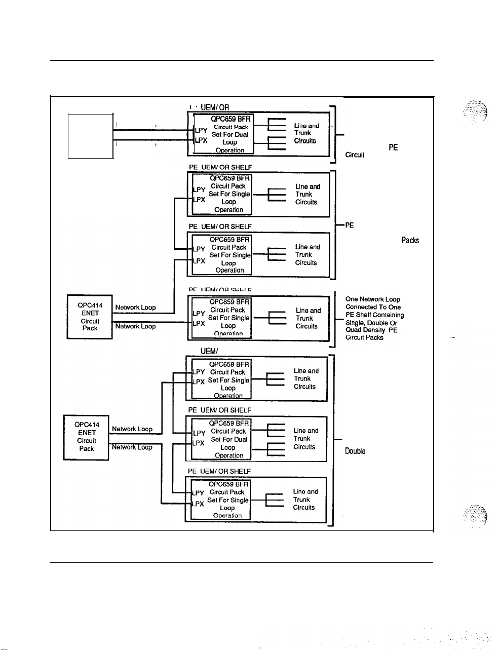
For peripheral equipment housed in NT8D13 PE modules, network capacity
may be allocated in single lcop mode and dual loop mode. In single-loop
mode, one peripheral equipment module is connected to one network loop,
yielding a maximum concentration of 160 terminations to 30 time slots. In
dual loop mode, half of the PE cards in a module use one loop, and the other
half use another loop, yielding two maximum concentrations of 80
terminations to 30 time slots.
System overview 553-3001-100
.
Page 27
20 System architecture
Figure 2
Single and dual loop configurations
QPc414
ENET
Circuit
Pack
Network Loop
Network Loop
PE UEMIOR SHELF
PE UEMI OR SHELF
$F[
PE UEMl OR SHELF
Two Network Loops
Connected To One
PE Shelf Containing
Single, Double Or
Quad Density PE
Ctrcuit Packs
One Network Loop
Connected To Two
-PE Shelves Containing
Single Or Double
Density PE Circuit
Pa&s
System overview 553-3001-l 00
Combined
Single And Dual
Loop Connections
To Three PE Shelves
Containing Single Or
Double Density PE
Circuit Packs
Page 28

System architecture 21
Superloop Network Configurations
The Superloop Network Card combines four regular network loops to make
120 timeslots available to PE cards housed in Intelligent Peripheral
Equipment Modules. This increased bandwiath and larger pool of timeslots
increases the network traffic capacity by 25% for each 120 timeslot bundle.
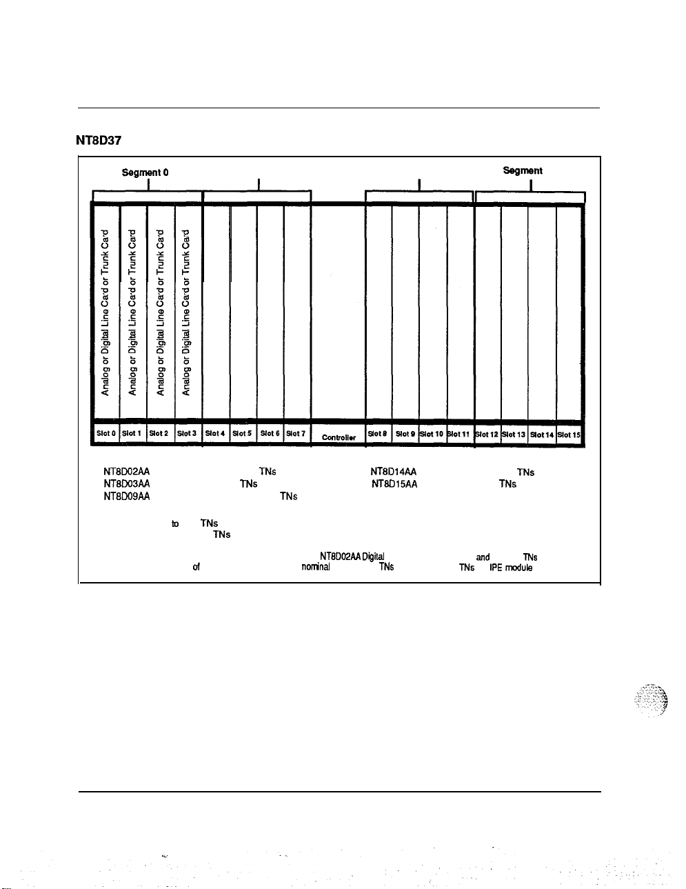
The NT8D37 Intelligent PE Module is divided into segments of 4 card slots.
These segments are numbered O-3. Segment 0 consists of PE slots O-3,
segment 1 consists of card slots 4-7, segment 2 consists of card slots 8-11,
and segment 3 consists of card slots 12-15.
A Superloop may be assigned from one to eight Intelligent PE segments. A
number of different superloop to segment configurations are possible. The
configuration chosen will depend upon system traffic requirements and the
specific PE cards used. Figures 4 through 9 illustrate different superloop to
segment configurations. Note that the TN to Timeslot concentration figures
(figure 3) are nominal, and may vary from segment to segment.
‘-
System overview 553-3001-100
Page 29
22 System architecture
Figure 3
NT8D37 lntellegent Peripheral Module segmentation
segment 0
Line Cards:
NTBWPAA Digital Line Card 16 to 32 TNs
NT8W3AA
NTBDOSAA Message Waiting Line Card 16 TNs
TN density:
Per segment 16 iu 128 TNs
Per IPE module 64 to 512 TNs
Note: Maximum TN density assumes ail slots equipped with
provisioned. Typical mix of line and trunk cards yields a
Analog Line Card 16
segment 1
MS
NT8DMM
nor&al
density of 64 TNs per segment. 256 TNs per
segment2 --
Trunk Cards:
NTBD14AA Universal Trunk Card 8 TNs
NT8DlMA
Diiital Line Cards with 16 voice and 16 data TNs
E&M Trunk Card 4 TNs
Segment 3
IPE
module
System overview 553-3001-l 00
Page 30
,.‘i‘...
:::.--:., ,\*
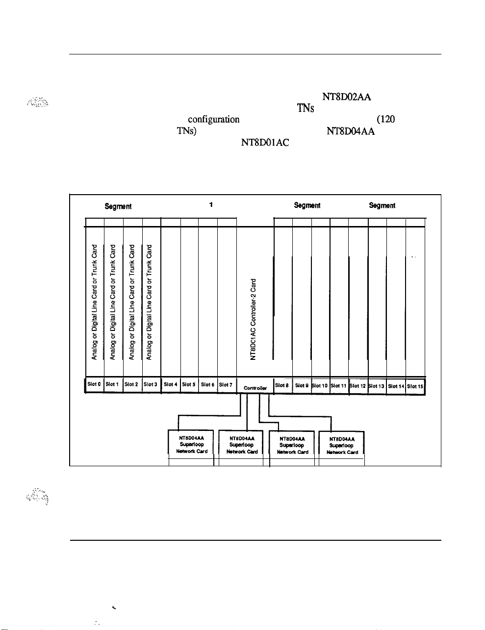
1 segment per Superloop
In this configuration, 1 segment is assigned to 1 Superloop (see Figure 4).
In cases where the segment is populated with NT8DO2AA Digital Line
Cards with all 16 voice and all 16 data TNs provisioned, the.1 segment per
superloop configumtion will provide a virtual non-blocking (120 Timeslots
to 128 TNs) environment (see Figure 2) Four NT8DO4AA Superloop
Network Cards and one NT8DOlAC Controller-4 Card are used to
implement a 1 segment per superloop configuration.
Figure 4
1 segment per Superloop configuration
Segment
segment
0
I
I
1
I I
System architecture 23
Ssgmem 2 Segment 3
I
I
.:-__
. ?. ,
.:.:y .:
- .. .*I
.-,
System overview 553-3001-l 00
c
:
.
.
Page 31

24 System architecture
2 segments per Superloop
In this configuration, 2 segments are assigned to 1 Superloop (see Figure 5).
In cases where the segment is populated with NT8DO2AA Digital Line
Cards with no data TNs enabled, NT8DO3 Analog Line Cards, NT8Do9AA
Message Waiting Line Cards, or NT8D14AA or NT8D15AA Tnmk Cards,
the 2 segment per superloop configuration will provide a virtual non-
blocking (120 Timeslots to 32-128 TNs) environment (see Figure 2). For
instances where half of the data TNs on NT8DO2AA Digital Line Cards are
enabled, this configuration still provides a low concentration of TNs to
timeslots (120 Timeslots to 1% TNs) and a very low probability of
blocking. Two NT8DO4A.4 Superloop Network Cards and one
NT8DOlAD Controller-2 Card are used to implement a 4 segment per
superloop configuration.
Figure 5
2 segments per Superloop configuration
System overview 553-3001-100
Page 32

4 segments per Superloop
In this configuration, 4 segments are assigned to 1 Superloop (see Figure 6).
In cases where the segment is populated with NT8DO2AA Digital Line
Cards, NT8DO3 Analog Line Cards, NT8DO!JAA Message Waiting Line
Cards, or NT8D14AA or NT8DlSAA Trunk Cards, the 4 segment per
superloop configuration will provide a medium concentration (120
Timeslots to 64-256 TNs) environment (see Figure 2). In instances where
half of the data TNs on NT8DO2AA Digital Line Cards are enabled, this
configuration provides a concentration of 120 Timeslots to 384
NT8DO4AA Superloop Network Card and one NT8DOlAD Controller-2
Card are used to implement a 4 segment per superloop configuration.
Figure 6
4 segments per Superloop configuration
System architecture 25
TNs.
One
System overview 553-3001-100
Y
:
Page 33

26 System architecture
8 segments per
SUperlOOp
In this configuration, 8 segments are assigned to 1 Superloop (see Figure 7).
ln
cases where the segment is populated with NT9IO2AA Digit& Line
Cards, NT8DO3 Analog Line Cards, NT8DO!JAA Message Waiting Line
Cards, or NT8D14AA or
NT8DlSAA
Trunk Cards, the 8 segment per
superloop configuration will provide a high concentration (120 Timeslots to
128-512 TNs) environment (see Figure 2). In instances where half of the
data TNs on NT8DO2AA Digital Line Cards are enabled, this configuration
provides a concentration of 120 Timeslots to 768 TNs. One NT8DO4AA
Superloop Network Card and two NT8DOlAD Controller-2 Cards are used
to implement an 8 segment per superloop configuration.
System overview 553-3001-l 00
. .
Page 34

..- _
.:.y;- _T.
,, ..:+
I
I,. .
: -:: :
..T .,
System architecture 27
Figure 7
8 segments per Superloop configuration
. . .
_:,
System overview 553-3001-100
Page 35

28 System architecture
1
segment per
Superloop
segmenis per Superloop
In this configuration, 1 segment is assigned to 1 Superloop and an additional
3 segments are assigned to another Superloop (see Figure 8). This
configuration provides a virtual non blocking environment for the single
segment served by the
fiist
Superloop and a medium concentration of
to Tiieslots for the 3 segments assigned to the additional Superloop, as
described in the preceding examples. Two NT8DO4AA Superloop Network
Cards and one NT8DOlAD Controller-2 Card are used to implement a 1
segment and 3 segment per superloop configuration.
Figure 8
1 segment per Superloop/ segments per Stiperloop configuration
TNS
r
segmsnt 0
Segment 1
ir
lot4 JotI
ssgmml2
I
Cmtrdlr
r
-
-Serves
I
nt,:
segments l-3
System overview 553-3001-I 00
.
Page 36

System architecture 29
2
segments per Superloop/ segments per Superloop
In this configuration, 2 segments are assigned to 1 Superloop and an
additional 6 segments are assigned to another Superloop (see Figure 9).
This configuration provides a virtual non blocking environment for the two
segments served by the first Superloop (or a very low concentration of TNs
to Timeslots when some data
T’Ns
are enabled) and a medium concentration
of TNs to Timeslots for the 3 segments assigned to the additional superloop,
as described in the preceding examples. Two NT8DO4AA Superloop
Network Cards and two
NTSWlAD
Controller-2 Card are used to
implement a 2 segment and 3 segment per superloop configuration.
:
System overview 553-3001-100
.
Page 37

30 System architecture
Figure 9
2 segments per
Superloop/
segments per Superloop configuration
System overview 553-3001-100
c
Page 38

Peripheral Equipment
Peripheral Equipment consists of peripheral controller cards which provide
the timing and control sequences for peripheral circuits, analog and digital
line and trunk cards, which provide the interfaces for terminal devices, and
circuit cards which provide Digital Trunk Interface (DTI),and Primary Rate
Access (PRA) services.
The peripheral controller performs the first stage of multiplexing signals
from the terminals, which are then passed on to the network for digital
switching. The peripheral controller also transmits timing signals, and
carries out other functions associated with the control of the peripheral
circuits.
The line card converts incoming analog signals into digital signals which
are then passed on to the peripheral controller. This conversion is
accomplished by an integrated encoder/decoder (codec) chip. There is a
codec for each port on the line card. Conversion from digital back to analog
is also performed by the codec for outgoing signals. For digital telephones,
the codec is located within the telephone set itself.
PCM
Pulse Code Modulation (PCM) is used to convert analog signals to digital
signals. The PCM method converts the analog signal to digital by samplin.g
the amplitude of the analog signal at a rate of twice the highest signal
frequency and converting the amplitude of each sample into a series of
coded pulses. The PCM sampling frequency standard for
telecommunications is 8 kHz.
System architecture
31
Companding (compressing - expanding) PCM is a standard technique for
using 8 bits words to efficiently represent the wide dynamic range of voice
and data signals. Two standards for companding are internationally
recognized:
Mu-255 law for North American applications
A-law for international service
Meridian 1 codecs conform to both standards and are software selectable (in
Intelligent Peripheral Equipment Modules) for use in North America and
internationally. The codecs are also designed to pass signals up to 3.4 kHz
System overview 553-3001-100
.
.
Page 39

32 System architecture
with minimum time delay and low phase distort&, a requirement for the
proper transmission of data signals.
Remote Peripheral Equipment (RPE)
In a local operating environment, the peripheral equipment may be housed
up to 50 feet from the common equipment. The RPE feature extends this
range to approximately 70 miles between local and remote facilities. This
extension is made possible by converting the multiplexed loop signals to a
form compatible with the commonly used T-l type digital transmission
system.
Any medium conforming to DS-1 format (1.544 Mbps) may be used to link
local and remote sites, including digital microwave radio and fiber optic
transmission systems.
DTVPRI
Allocation of circuit-switched bandwidth may also be made on a network-
loop basis to Primary Rate Access (PRA) or Digital Trunk Interface (DTI)
circuits. These optional services are based on the standard T-l format
(DS-1 24 channel) used in digital transmission networks.
DTI allows for the replacement of 24 conventional analog trunks by a single
T-l digital link. Each of 24 channels provides up to 56 Kbps for voice and
synchronous data transmission, or up to 19.2 Kbps for asynchronous data.
--
Power equipment
Meridian 1 systems feature a modular power distribution architecture which
parallels the modular design concept of the Universal Equipment Module.
Meridian 1 power systems provide the following features:
-
AC-powered and DC-powered system options, providing flexibility to
meet a wide range of customer requirements.
-
A distributed, modular power architecture, with power supplies located
in each Module, rather than in separate, centralized power shelves.
-
All DC systems are available as complete systems, with rectifiers
provided by Northern Telecom, or can be equipped for customer-
provided external power.
System overview 553-3001-100
Page 40

System architecture 33
-
A new System Monitor has been designed to provide enhanced power,
cooling, and general system monitoring capabilities. This new System
Monitor interfaces to the CPU via a Serial Data Interface card, for
intelligent error and status reporting.
-
Maintenance messages that indicate the location of power faults and
-
status down to the specific Column and Module.
-
Equipment modules that are truly Universal, in terms of power and
cooling. Meridian 1 systems are designed to eliminate power and
thermal limitations: any card can go in any slot, and all modules can be
filled to capacity with any logically valid combination of cards, with
virtually no engineering rules.
-
A universal quick-connect power wiring harness is used to distribute
input voltages and monitor signals to power supplies located in each
Module.
-
An advanced cooling system which employs forced air impellers. The
.-
velocity of the impellers is automatically adjusted to meet the cooling
requirements of the system.
-
Fuses are eliminated, as the system exclusively uses circuit breakers for
input power protection.
-
Modular backup capabilities.
AC and DC systems differ primarily in the power components external to
the UEM. See Figures 8 and 9 for block diagrams of the AC and DC
powering schemes. DC systems always require the use of rectifiers. This
can be a disadvantage in applications that do not require reserve power
backup in the event of a utility power failure.
The use of a rectifier in DC
powering is an advantage in applications that do require battery backup,
since all that is needed is to add batteries, as in the traditional central office
powering scheme.
AC-powered systems are especially well-suited for those applications that
do not require reserve power, as there are no external power components
required. There are a wide variety of Uninterruptible Power Supply (UPS)
systems available for AC systems that require reserve power, and the use of
a UPS is an effective method of providing backup power in many situations.
System overview 553-3001-100
Page 41

34 System architecture
The choice of which powering scheme to use is determined primarily by
reserve power requirements and preferences, and by existing power
equipment at the installation site.
Figure 10
AC power architecture
Battery
Bank
I
I
AC
inp
UPS
RkXXifkI
---
w
DC
AC POWERED SYSTEM
(with reserve power )
fgg
Required i --
0
Optional 1
,
‘
,.--,-..
,:,..: .i
:
.:
:
j
System overview 553-3001-100
Page 42

Figure 11
DC power architecture
DC POWERED SYSTEM
(with reserve power)
System architecture 35
System overview 553-3001-l 00
.d
:
Page 43

36 System architecture
System overview 553-3001-l 00
z..
:
:
Page 44

Product description
Universal Equipment Modules
The Meridian 1 System is comprised of Universal Equipment Modules
(UEMs), each containing everything needed (card cage assembly, power
supply, I/O cabling, etc) to support a specific system function. These UEMs
are assembled up to four high on a pedestal, to form a column. The pedestal
contains a central Power Distribution Unit (PDU), cooling fans, air filters,
and a System Monitor circuit. At the top of each column is a Top Cap,
which consists of two air exhaust grilles and a thermal sensor assembly that
works in conjunction with the System Monitor. Systems are comprised of
one or more columns. Each Universal Equipment Module is available in
AC or DC powered versions.
The Universal Equipment Modules are constructed of die cast aluminum,
providing strength and durability. For ease of access each module has
removable front and rear covers. All cable routing between the module and
the Main Distribution Frame (MDF) is handled through the rear of the
module. Cable exit can occur at the top, to access overhead cable racks, or
at the bottom to take advantage of raised floors. Universal Equipment
Modules are assembled on a pedestal that houses a central Power
Distribution Unit, cooling units and system monitor circuitry. The pedestal
can be equipped with either leveling feet or casters. UEMs may be
assembled in columns up to four high.
37
.:;
,_ \ .y’..
::: -:‘ .‘. :
The following Universal Equipment Modules are available:
-
1
.
CPU module
-
CPU/Network module (NT6D39)
-
Network Equipment module (NT8D35)
(NTSD34)
System overview
553-3001-l 00
Page 45

38 Product description
-
-
-
-
Common/Peripheral Equipment module
(NT8Dll)
Intelligent Peripheral Equipment module (NT8D37)
Peripheral Equipment module (NT8D13)
-
Remote Peripheral Equipment Carrier module (NT8D47)
.
- InterGroup
-
Meridian Mail module
Figure 12
Universal Equipment Modules
module
(NT8D36AA)
(NT6D44)
Universal Equipment
\
Univwbsl Equipment
Top-P
System overview 553-3001-l 00
Page 46

CPU module (NT8D34)
The NT8D34 CPU module houses the CPU and Memory cards used to
provide system control and storage of data and programs, for the Meridian 1
system option 71. Each NT8D34 CPU module houses one CPU; two are
required for the Meridian 1 system option 71. For configuration flexibility
the NT8D34 CPU module is available with an AC power supply option or a
DC power supply option. These power supplies provide the voltages to
operate the circuit cards located in the modules.
The NT8D34 CPU module contains 17 card slots which support the
following:
-
slots l-2 : Memory
-
slot 3: CMA
-
slot 4: CPU Interface
-
slot 5: CPU Function
-
slot 6:
SD1
-
slot 7:
MS1
-
slots 8-12: Segmented Bus Extender (SBE)
-
slot 14: Clock Controller
-
slot
15-
17: FDU/MDU or Digital Trunk Interface (DTI)jPrimary Rate
Interface (PRI)
Product description 39
-
--
System overview 553-3001-l 00
Page 47

40 Product description
Figure 13
NT8D34 CPU module -typical configuration
I
!
SL-1
CE
Module
~CPU/Mem
-
Common Equipment
System overview 553-3001-100
c
Page 48

Product description 41
CPU/Network module
The NT6D39 CPU/Network module houses the CPU and Memory circuit
cards used to provide system control and storage of data and programs for
Meridian 1 system option 51 and 61. Each NT6D39 module houses one
CPU and up to 16 network loops required for each Meridian 1 system
option 51 and 61.
For configuration flexibility the NT6D39 CPU/Network module is available
with an AC power supply option or a DC power supply option. These
power supplies provide the voltages to operate the circuit cards located in
the Modules.
For a half group, single CPU system (Meridian 1 system option 51) one
NT6D39 module is required. For a full group, dual CPU system (Meridian
1 system option 61) two NT6D39 Modules are required.
The NT6D39 contains 17 card slots which support the following:
-
slots 1 - 8: Network cards
-
slot 9 : Clock Controller or Serial Data Interface (SDI)
-
slot 10: Peripheral Signaling
-
slot 11: 3-Port Extender (3PE)
-
slot 12: Mass Storage Interface (MSI)/Floppy Disk Interface (FDI)
-
slot 13:
-
slot 14: CPU Function
-
slot 15: CPU Interface
SD1
-(NT6D39)
.-
-
slot 16: Changeover Memory Arbitrator (CMA)
-
slot 17: Memory
-
slot 18: FDWMDU
!
_:..
.,
: : ,
.:: ‘-1 .:
.;
: -.
1
System overview 553-3001-100
Page 49

42 Product description
Figure 14
NT8D39 CPU/Network module -typical configuration
;L-1
CE Module
1
Net
I CPUAkm
System overview 553-3001-l 00
Page 50

Network module (NT8D35)
The NT8D35 Network module houses the circuit cards which are used to
provide the digital multiplexed network loops of the switch.mg system,
along with the control and signalling cards
switching function with the CPU. The NTSD35 Network Module is used in
Meridian 1 system option 71 only. The NT8D35 module also supports
Digital Trunk Interface (DTI) and/or Primary Rate Interface
For configuration flexibility the NT8D35 Network module is available with
an AC power option or a DC power option. These power supplies provide
the voltages to operate the circuit cards located in the modules.
The NT8D35 Network module houses up to eight QPC414 (ENET) cards or
four NT8DO4AA SuperLoop Network cards, or any combination for a total
of 16 network loops per module. In a typical configuration, 14 voice/data
loops are available when one NT8D17 Conference/Tone and Digit Switch
card is configured in the module. Two NT8D35 modules are required to
make a full network group of 32 loops. A maximum of 10 NT8D35
Modules (5 network groups) may be configured.
The NT8D35 contains 15 card slots which support the following:
-
slots 1: 3PE
-
slots 2-3: InterGroup Switch (IGS) 1, DTWRI, or
-
slot 4: Peripheral Signaling
-
slots 5-12: Network Cards
-
slot 13: DTI/PRI or SDYQSDI
rquired
Product description
to interface the
@‘RI)
cards.
SD1
43
,i
1
j _:: ..i- ..
i:, ,,Y.. ..‘,,
. . . .
.
..‘.
!
,,. /’
:.
-
slot 14:
-
slot 15: not used
DTI/PRI
System overview 553-3001-100
Y
Page 51

Page 52

Product description 45
Common/Peripheral Equipment modute
The
NT8Dll
equipment circuit cards for Meridian 1 system options 21A and 21.
The
NT8Dll
These power supplies provide the voltages to operate the circuit cards
located in the modules.
The
NT8Dll
-
Common Equipment (CE)
-
Peripheral Equipment (PE)
There are 10 Common Equipment (CE) and 10 Peripheral Equipment (PE)
card slots. The CPU functions are provided by card slots 1-3. The Network
Equipment functions are provided by card slots 3-10.
The
NT8Dll
Meridian 1 System Options 21A and 21 only.
-
Memory/Signaling card (NT8D19AA) - provides the peripheral
signaling functions in addition to providing the memory and
miscellaneous CPU equipment functions.
-
Network/DTR card (NT8D18AA) - provides the Controller card
(NT8DOl) functions for the Intelligent PE cards installed in the
NT8Dll
Receiver functions.
module houses the common, network and peripheral
CE/PE module is available
CE/PE module is divided into two functional sections:
module will utilize two specially designed circuit cards for
module, along with a SuperLoop Network and Digitone
intwo
(NT8Dli)
versions, AC or DC power.
--
The NTSDl 1 module uses the new Intelligent Peripheral Equipment cards
to provide trunk and station interface in system options 21A and 21.
System overview 553-3001-100
Page 53

46 Product description
The
following:
-
-
-
-
-
-
-
NT8Dll
CE/PE Mod&e contains 20 card slots which support the
slot 1 : FDI
slot 2 : CPU
slot 3: Memory
slots 4-8: Network cards
slot 9: Conference/Tone and Digit Switch card (N’lXD17AA)
slot 10: Network/DTR card (NT8D18AA) (Always configured
as SuperLoop 28)
slots O-9: Intelligent Peripheral Equipment cards only
System overview
. .
5!53-3001-100
Page 54

.-.;
:,::,
,. ,:,_ ,:,:,+
,.. :(
.!
:
Page 55

48 Product description
Intelligent Peripheral Equipment module (NT8D37)
The Intelligent Peripheral Equipment module uses the new Peripheral
Equipment cards only and may be used with system options 21A,.21,51,
61,7
modules may be used with all existing systems.
The NT8D37 Intelligent PE module is available in two versions, AC or DC
power. These power supplies provide the voltages to operate the circuit
cards located in the modules.
The NT8D37 module may only be connected to a SuperLoop Network
(NT8DO4AA) circuit card. It houses one Controller card (NT8DOl) and up
to 16 Intelligent Peripheral Equipment circuit cards. The card slots are
numbered from 0 to 15, for a total of 16 PE card slots.
The NT8D37 Intelligent PE module supports 16 PE circuit cards, yielding a
capacity of 256 Integrated Voice/Data (IVD) lines (512 TNs), although a
typical configuration includes a mixture of Digital lines, Analog lines,
Trunks and Digitone Receiver (DTR) circuit cards.
All cable connections to the MDF are made in the rear of the module
through an I/O panel. To serve all 16 PE card slots, 12 PE cables are
required to the MDF.
1. With an upgrade assembly the Intelligent Peripheral Equipment
System overview 553-3001-100
.
Page 56

Figure 17
NT8D37
Intelligent PE module-typical configuration
1
IPE
0
@
PE Pwr Sup
LJ
II
Product description 49
.
System overview 553-3001-100
.
.
Page 57

50 Product description
Peripheral Equipment module (NT8D13)
The Peripheral Equipment module uses the PE circuit cards currently
housed in PE shelves for the Meridian SL-1 systems. It provides the
interface to the system for trunks and stations. The NT8D13 module may
only be connected to an ENET (QPC414) circuit card and maybe used in
system options 21A,
N, and XN systems. It houses one Peripheral Buffer circuit card (QPC659)
and up to ten existing peripheral equipment circuit cards.
When the Meridian Data Service ADM, SADM, ASIM or AIM are required
on system options 21A,
used.
For configuration flexibility the NT8D13 Peripheral Equipment module is
available with an AC power supply option or a DC power supply option.
These power supplies provide the voltages to operate the circuit cards
located in the Modules.
All cable connections to the MDF are made in the rear of the module
through an I/O panel. Seven PE cables are required to the MDF for all 10
card slots.
21,51,61,71
21,51,61,
and the Meridian SL-IXT, NT, RT, ST,
and 71, the NT8D13 PE module must be
System overview 553-3001-l 00
.
.
Page 58

$
It-l
F
?
5
I
Analog or Dgital Line Card or Trunk Card
*IAnalog or Dgilial Line Card cr Trunk Card
Analog or Dgital Line Card or Trunk Card
I
II 211
-II
Iill
I
B
$
ltlt
3
WC659 Peripheral Buffer Card
Analog or Dgillal Line Card or TrunkCard
Analog or Dgtial Line Card or Trunk Card
Analog or
Dgflial
Line Card or Trunk Card
Analog or Dgltial Line Card or TrunkCard
Analog or Dgltial Line Card or Trunk Card
I
I
Page 59

52 Product description
Remote Peripheral Equipment Carrier module (NT8D47)
The NT8D47AA/DC RPE Carrier module is used to extend the Network to
PE interconnection distance between local and remote sites. It,
accommodates two network loops. The number of modules required per
system depends on the number of stations in the remote site.
For configuration flexibility the Remote Peripheral Equipment Carrier
module is available with an AC power option or a DC power option. These
power supplies provide the voltages to operate the circuit cards located in
the modules.
The RPE backplane contains 12 card slots which support the following:
-
-
-
-
-
-
-
-
-
-
-
1
slot 1: DTI
slot 2: 1.5 Mb Converter
slot 3: 2 Mb Converter
slot 4: Carrier Interface
slot 5: Remote Peripheral
slot 6: Local Carrier Buffer
slot 7: Carrier Interface
slot 8: 2 Mb Converter
slot 9: 1.5 Mb Converter
slot 10: Carrier Maintenance
slots 1 l-12: DTI
System overview 553-3001-l 00
Page 60

Figure 19
NT8D47
RPE Carrier module -typical configuration
Product description
53
%.
System overview 553-3001-100
Page 61

54 Product description
InterGroup
The InterGroup module provides a path for the switching of traflic between
the network groups in system option 71. Faceplate cables from Segmented
Bus Extender (SBE), System Clock (SCG) and InterGroup Switch (IGS)
circuit cards are connected to the InterGroup module. These faceplate
cables are accessed from the front of the module.
The InterGroup module does not require any power card for operation.
Therefore it may be used with systems using the AC power option or the
DC power option.
Figure 20
NT6D36AA InterGroup
I I\
module
module
(NT8D36AA)
/II
System overview 553-3001-l 00
.
.
Page 62

Product description 55
;:. ..:,=-,
I./
._ ./
I.. .,
j! II --.--x..:~:;
-.
. .
. .
.
Meridian Mail module (NT6D44)
The NT6D44 Meridian Mail module houses the circuit cards currently used
by the Meridian Mail Option for Meridian SL-1 systems: The NT6D4.4
Meridian Mail module may only be connected to an ENET (QPC4 14)
circuit card and may be used in Meridian 1 system options 21A,
71 and the Meridian SL-1 XT, NT, RT, ST, N, and XN systems.
For configuration flexibility the NT6D44 Meridian Mail module is available
with an AC power supply option or a DC power supply option. These
power supplies provide the voltages to operate the circuit cards located iu
the Modules.
Meridian 1 system option 21A must be upgraded to Meridian 1 system
option 21 when the NT6D44 Meridian Mail module is equipped.
21,51,61,
System overview 553-3001-100
c
:
.
.
Page 63

56 Product description
Figure 21
Meridian Mail module
-typical configuration
\
Circuit breakers
for Power
sup+3
\I
Common Equipment
Power St&ply
MERIDIAN MAIL MODULE
V
Hard Disk
Modules: NT4G5QAG
155MB-NT6D46AA
2OOMBNT6D47AA
6OMB.NT6D46AA
smdr
corrputer
,;;;ym Bus
&h
Availabiliiy
Controller
NT4RO6M
(multiple
ncdes)
or
Random
AC-8
Memory CcmpMer Eloerd
NT4G5gAF
(sing* de)
NT6D44
/
Enhanced Single
/I
NT4ROBAA
. .
N.h!oJLe
PIDCWSU
NT4RolAA
(Maidan 1
or
GMWd
wrpo=
signal vcica
PfOWstuw
NT4RwAA
(Meridian tW
or DMS-loo)
RS-232
’
.setice
wle
NT4ROW
System overview 553-3001-100
Page 64

Pedestal (NT8D27AB)
The NT8D27AB pedestal is a base unit made of die-cast construction and
houses the power distribution unit, system monitor, blower unit, and fan
unit connector. One pedestal is required per equipment column.
The pedestal is approximately 31.5 inches wide by 25.50 inches deep by 10
inches high and weighs 30 lbs empty. Leveling feet are provided for up to
four tiers, while a caster option is provided for up to two tiers. Input power
for the system is brought into and distributed by the pedestal. A Power
Distribution Unit located in the pedestal contains an EMI filter and one 30
amp circuit breaker.
One pedestal distributes the input power for one column. Also located in
the pedestal are two forced air impellers and a reusable dust filter. The
impellers are protected by two 1 amp circuit breakers.
Product description
57
Top cap
(NT7DQO)
The top cap is mounted on the top module of each column. It provides
additional EM1 shielding, air exits, and I/O cable exits.
The top cap is approximately 31.5 inches wide by 22 inches deep by 3
inches high and weighs 8 lbs. It consists of a front and a rear air exhaust
grills, each secured by two clips underneath the edge of the grill.
Three versions of the top cap are available:
- NT7DOOAA AC systems
- NT7DOOBA DC systems
- NT7DOOAB Meridian 1 System option 21A only
Expansion kit (NT8D49)
The Expansion kit bolts modules together for side-by-side expansion when
in a contiguous row. The Expansion kits also maintain shielding against
EMI/RFl. See Figures 22 and 23.
.-
._
System overview 553-3001-100
Page 65

58 Product description
Figure 22
Multi-column system equipped with NTBD49 Expansion kits
NT8D49
Expansion
Kits
System overview 553-3001-l 00
Page 66

NT8D49 Expansion Kit
Product description 59
Spacer
System overview 553-3001-l 00
Page 67

60 Product description
Meridian 1 system options
Several system options are available. The use of the Universal Equipment
Modules allows for seamless growth from one option to another by adding
or replacing Universal Equipment Modules or card cages. The options are
selected depending upon the application, line size, and other customer
requirements:
-
Meridian 1 system option 21A - Single CPU-l module only
-
Meridian 1 system option
-
Meridian 1 system option
-
Meridian 1 system option
-
Meridian 1 system option
Meridian 1 system option 21A
The Meridian 1 system option 21A package includes the CE/PE base
hardware, 1 Network/DTR card, 1 Conf/TDS card, 1 Floppy Disk Unit
(FDU), 2
added. These assemblies include a Top Cap-21A, System Monitor-21A,
Pedestal, AC power cord and a power distribution Unit-21A. The Meridian
1 system option 21A supports only the AC power option.
SD1
paddle boards. The Pedestal and Top Cap assemblies must be
21-
Single CPU
51-
Single CPU, Half Network Group
61-
Dual CPU, Full Network Group
71-
Dual CPU, Multiple Network Groups
Figure 24
System option 21 A
System overview 553-3001-I 00
Page 68

Table 1
System
Product description 61
option 21A specifications
Power
Typical Number of Ports
Maximum Number of Ports
Maximum Number of Modules
AC Input Voltage
Number of CPUs
Number of Network Loops
l
Cooling
Memory
Data Storage
Software Generic
Hardware Features
Note:
Additional network loops require expansion modules
(Intelligent PE or Peripheral Equipment Modules).
AC only
160
320
1
208
V ac
1
7 SuperLoops or 12 ENET Loops plus two
service loops (Conf/TDS)
Fan in Top Cap
768K
Floppy Disk Unit
1011 Rls 15
No Power Distribution Unit Contains
System Monitor (NT7D15AA)
System overview 553-3001-100
Y
Page 69

62 Product description
Meridian 1 system option
21
The Meridian 1 system option 21 package includes the CEjPE base
hardware, 1 Network/DTR card, 1 Conf/TDS card, 1 Floppy Disk Unit
(FDU), 2
SD1
paddle boards. The Pedestal and Top Cap assemblies must be
added. Figure 25 illustrates a typical configuration with the shaded area
showing the base package.
Figure
25
System option 21
System overview 553-3001-100
Page 70

.;. _,
,‘)
2;:
‘,i,
,’ .” . ..’ ,y
-. :,
,-,z
Table 2
System option 21 spcifications
Power
Maximum Number of Ports
Input Voltage
Number of CPUs
Number of Network Loops
Cooling
Memory
Storage Media
Software Generic
Hardware Features
Product description 63
AC or DC
800
208Vacor-48Vdc
1
7 SuperLoops or 12 ENET Loops plus two
service loops (Conf/TDS)
Fan Impellers in pedestal
768K
Floppy Disk Unit
1011 Rls 15
Standard Power Distribution Unit Contains
System Monitor (NT8D22AB)
;..
‘:.
3
: .., ._,!
,::
.)
System overview 553-3001-l 00
c
Page 71

64 Product description
Meridian 1 system option 51
The Meridian 1 system option 51 package includes 1 CPU/Network module,
1 Conference and TDS card, 1 SuperLoop
boards, 1 Intelligent Peripheral Equipment module, 1 Pedestal assembly
and 1 Top Cap. The FDU or MDU assembly must be added. Figure 26
shows a typical system configuration with the shaded areas showing the
base package.
Figure 26
System option 51
I
I
Universal
Equipment
Module
NetworJc
u
card, 2
SD1
paddle
System overview 553-3001-l 00
r
Ufliversal
Equipment 1111
‘tlll
Page 72

Table 3
System option 51 specifications
Product description 65
Power
Maximum Number of Ports
Input Voltage
Number of CPUs
Number of Network Loops
Cooling
Memory
Storage Media
Software Generic
Hardware Features
AC
or DC
1000
208 V ac or -48 V
dc-
1
16
Fan Impellers in pedestal
768K
Floppy Disk Unit
or
Multi Disk Unit
1111 Rls 15
One Half Network Group, Standard Power
Distribution Unit Contains System Monitor
(NT8D22AB)
:, ..-:.- ‘:;.
-‘.,.
:
.;
‘L :,
‘: !
System overview 553-3001-100
Page 73

66 Product description
Meridian 1 System option-61
The Meridian 1 System option 61 package includes 2 CPU/Network
Modules,
paddle boards, 1 Intelligent Peripheral Equipment module, 1 Pedestal
assembly and 1 Top Cap. The FDU or MDU assembly must be.added.
Figure 27 shows a typical system configuration with the shaded areas
showing the base package.
Figure 27
System option 61
2 Conference and TDS cards, 1 SuperLoop Network card, 2
niversal
Universal
Equipment
SD1
~g”“‘&‘~y~~~
.................
........
r
::::::::i:;:::i:
........
I-~:::~~
........
.........
......... .
.......
......... ..
......
........
.
..
.:.~:...:...:.:.:.::::::::
.............................
. ii
. .
. .....
IY
..
:.: .....
.................
...........
............
........ ..................
--
h
~:( ._,
~
.. ..: .>
.........
..
............. .
........
......................
..
.. . .... ... .
::::.:.:.~.:.:.:.:.:.:.:.:.:.:.:
......................
.............................
..... .........
..:.:.:.:.:.:.: .: ........
................................
iiiiiiiiiii~~~~~~~~~~~~~~~~~~.~~~~~~~~~~~~~~~~
~CPl-
..........
.........
........
..........................
....................
.....................
....................
System overview 553-3001-l 00
.
.
.
Page 74

_I
‘,j
j
.<..:. 1 :;.‘.
;,:.:;,
2;
1
.
. .
Table 4
System option 61 specifications
:
Power AC or DC
;._,
(,
Maximum Number of Ports 2000
Input Voltage
Number of CPUs 2
Number of Network Loops
Cooling
Memory
Storage Media
Software Generic
Hardware Features
Product description 67
1208Vacor-48Vdc
32
1
Fan Impellers in pedestal
768K
Floppy Disk Unit or Multi Disk Unit
I1111
Rls 15
I
1
One Network Group, Standard Power
Distribution Unit and Contains System
Monitor (NT8D22AB)
I
I
I
I
I
.-
I
System overview 553-3001-100
‘...
Page 75

68 Product description
Meridian 1 system option 71
The Meridian 1 system option 71 package includes 2 CPU Modules, 1
InterGroup module, 1 Network Group assembly, 2 Conference and TDS
cards, 1 SuperLoop Network card, 2
Equipment Modules, 2 Pedestal assemblies and 2 Top Caps. The FDU or
MDU assembly must be added.
with the shaded areas showing the base package.
Figure 28
System option 71
SD1
cards, 2.Intelligent Peripheml
Figure 28 shows a typical configuration
System overview 553-3001-l 00
C.
:
Page 76

Table 5
System option 71 specifications
Product description 69
Power Distribution Unit and Contains
‘:
:;
:::‘:.:‘)
..-
. .
.
: :.: “C
, _. . -. A,
~
.,.E
:
.:::.::
::.
System overview 553-3001-100
Page 77

70 Product description
System overview 553-3001-l 00
.
.
Page 78

71
List
ACD
ADM
AIM
ALU
Architecture
ASIM
Analog
of
terms
Automatic Call Distribution.
Add-On Data Module.
Asynchronous Interface Module.
Arithmetic Logic Unit.
The interrelationship between the parts of a system. The framework of a
system.
Asynchronous/Synchronous Interface Module.
A process which models information in the form of a continuously varying
parameter such as current, voltage, or phase.
System overview 553-3001-100
Page 79

72 List of terms
Analog signal
ANI
Ampere
Backplane
Battery back-up
BISDN
A signal that varies in a continuous manner such as voice or music.
An
analog signal may be contrasted with a digital signal which represents only
discrete states.
The signal put out by a data set has both analog
.zuid
discrete
characteristics.
Automatic Number Identification.
A unit of electrical current or the rate of flow of electricity which is equal to
watts divided by volts.
A printed circuit board that extends throughout the length of the shelf and
connects to the circuit pack connectors.
Also known as a motherboard.
System power furnished by stand-by batteries that are charged by a charger.
If commercial power fails, the batteries will maintain service for a limited
period of time determined by the size of the batteries and the traffic on the
system.
Basic Rate Integrated Services Digital Network.
BTU
British thermal unit. The quantity of heat required to raise the temperature
of one pound of water one degree Fahrenheit at a specified temperature (as
39”
E).
Also means Bus Terminating Unit.
Capacity
The information-carrying ability of a telecommunications facility, group,
network, or system measured in Bits Per Second.
Cards
See circuit packs.
Card Cage
Also referred to as card chassis. A frame for holding circuit cards in a
microprocessor. A standard cage holds nine cards; units with motherboards
can hold up to 20 cards.
System overview 553-3001-l 00
Page 80

CAS
Centralized Attendant Service.
CASM
Centralized Attendant Service, Main.
CASR
Centralized Attendant Service, Remote.
cc
Clock Controller.
CDR
Call Detail Recording.
CE
Common Equipment.
Central Office (CO)
The site where the telephone companies terminate customer lines and locate
the switching equipment which interconnects those lines.
Central Processing Unit (CPU)
The main portion of a computer that contains the primary storage,
arithmetic and logic units, and the control unit; Mainframe.
List of terms 73
Centralized depot
A repair house for SL-1 systems that serves subdepots.
Centrex
Central Exchange. A telco PBX type of service incorporating Direct Inward
Dialing (DID) and Automatic Identification of Outward Dialed Calls
(AIOD).
Circuit packs
Also known as cards, circuit packs are individual circuit boards that carry
the necessary electronics for particular functions (memory, disk drive
control, etc. ). These cards lit into expansion slots provided by Apple,
IBM, Radio Shack, and other computer manufacturers.
ClwlA
Changeover and Memory Arbitrator.
. .
System overview
553-3001-100
Page 81

74 List of terms
co
Central Office.
CPU
Central Processing Unit.
Common equipment (CE)
A hardware subsystem that houses one or more Central Processing Units
(CPUs), memory circuits, mass storage devices, and service circuits.
Configuration
A group of machines (hardware) which are interconnected and are
programmed to operate as a system.
Data Terminal Equipment (DTE)
Equipment or devices which are capable of transmitting and/or receiving
data signals over a communications network commonly called a business
machine.
dB
Decibel
DCHI
D-Channel Handler Interface.
.-
Diagnostic programs
Software routines used to test equipment and pinpoint faulty components.
Digital
A process which models information as discrete values of some parameter
such as voltage, current, or phase. Compare with analog.
Digital Multiplex Switching System (DMS)
A family of switching systems using new technology that provides digital
circuit switched service for voice and data transmission. DMS is
characterized by the use of pulse code modulation (PCM) and time division
multiplexing (TDM) throughout the switched network. The system allows
the direct switching of PCM signals without their conversion to analog
format.
System overview 553-3001-l 00
Page 82

Digital signal
A signal made up of discrete, non-continuous pulses whose information is
contained in theirduration, periods, and/or amplitude.
Directory number
The four-digit number or extension given to a Meridian SL-1 telephone set.
Also known as DN.
DSL
Digital Subscriber Loop.
DTE
Data Terminal Equipment.
DTI
Digital Trunk Interface.
DTR
Digitone Receiver.
EIA
Electronics Industry Association.
EMI
Electromagnetic Interference. Unwanted electromagnetic coupling.
Examples are ham radio heard on electric organs and church music heard in
List of terms 75
hearing aids. Also known as QRM or “static.”
.i ,..:‘.(.. ..(
.;:,: ,._. .‘,’
_’
ESN
Electronic Switched Network.
Failure rate
The estimated number of failures for that item during one million (106)
hours of operation.
Firmware
A set of instruction sequences stored permanently in hardware (ROM).
FM
Frequency Modulation; A process whereby the frequency of a previously
single frequency carrier wave is varied in step with the amplitude of a
complex modulating wave. Also means Fully Modular.
System overview 553-3001-100
c
Page 83

76 List of terms
Frame
A distributing frame. The structure on which all distribution and trunk
cables into a central office are terminated (attached).
Frequency Division Multiplexing (FDM)
Combining two or more information channels into a single transmission
channel by assigning each information channel an exclusive frequency band
within the transmission channel bandwidth. (See “Multiplex” and “Time
Division Multiplex.
“)
I/O
Input/Output; Refers to devices that communicate with customer
The result equals a properly functioning communications channel or system.
I/O
Channel
Input/Output channel; A component in a computer system controlled by the
central processing unit that handles the transfer of data between main
storage and peripheral equipment.
I/O
Panel
A separation plane that prohibits RF (Radio Frequency) emissions from
passing through the cube and provides mounting for I/O cable connectors.
ISDN
Integrated Services Digital Network.
quipmcnt
‘-
IVD
Kbk
Line
Loop
MCDS
System overview
Integrated Voice and Data.
Kilobits
per second.
A communications channel or circuit an electrical path.
A bidirectional path between network equipment and peripheral equipment.
Multi-Channel Data System.
563-3001-100
. .
Page 84

MDF
List of terms 77
Main Distributing Frame. See “Frame” above.
::>;.. :::>
‘I
.>,
.
-“’ ..a -1
u :;.::
‘I.
,..:. .,
t
-.; >
MF
Multi-Frequency; A method of sending numerical address digits between
telephone company switching centers coded as two or more frequencies
between 300 and 3400 Hertz.
MFS
Multi-Frequency Signaling. Also means Multi-Frequency Sender.
MGS
Multi-Group Switch.
MSI
Mass Storage Interface.
MSL-1
Meridian SL- 1.
MSU
Mass Storage Unit.
Multiplex (MUX)
The process of combining two or more information channels into a single.
transmission channel. (See “Frequency Division Multiplexing” and “Time
Division Multiplexing.
Network equipment (NET)
A hardware subsystem that provides digital multiplexed switching for voice,
data, and signaling paths.
.-
“)
:
,.
:
:.:.-..1. :‘I
:
‘“< ._ -I / ,,
. . . . . .
.
.,
NFT values
NTP
..d
The number of spares required for a field-replaceable item. NFT is
calculated by multiplying the number (N) of that item in use by the failure
rate (F) for the item from Appendix 1 by the turnaround time
(T)
in hours.
(N X F X T = NFT value. ) See Appendix 1 for details.
Northern Telecom Publication.
System overview 553-3001-l 00
:.:
Page 85

78 List of terms
ODAS
Office data
PBX
PCM
PDU
PE
Pedestal
Office Data Administration System; provides a method of retrieving
administrative information stored in Meridian SL-1 memory.
Office data represents system configuration data, peripheral equipment data,
and transient data (temporary) used for call processing.
Private Branch Exchange.
Pulse Code Modulation,
Power Distribution Unit.
Peripheral Equipment.
Base assembly upon which Universal Equipment Modules are stacked; The
pedestal houses the Power Distribution Module, System Monitor, Blower
Module (and/or Fan assembly), Harnessing, and Air Grille and Filter units.
Peripheral equipment
A hardware subsystem that provides analog and digital telephone and trunk
interfaces and houses a combination of line, trunk, and receiver packs.
Population range
The quantity of each type of SL-1 switch in the area served by a repair-
house depot. See Appendix 1 for details.
Power supplies
Individual units that generate the different DC voltages required by
backplanes installed in a module. Their primary function is to provide
power to a shelf of cards housed within a UEM.
PRA
Primary Rate Access.
System overview 553-3001-100
:
Page 86

ISDN Primary Rate Interface.
Private Branch Exchange
PBX; A small telephone switching center enabling a customer’s telephone
stations to connect to the public switched network.
Private Exchange
A private (manual) telephone exchange that provides private telephone
service to an organization that does not allow calls to be transmitted to or
from the public telephone network.
PROPvl
Programmable Read-Only Memory.
Public Switched Network
The Direct Distance Dialing (DDD) telephone network; Any exchange type
of service that is made available for public use.
Pulse Code Modulation (PCM)
A modulation technique whereby the signal is converted from an analog to
digital format by sampling the signal at periodic intervals and digitizing the
amplitude into a finite number of discrete levels; Five-bit information code.
List of terms 79
. .
RAM
Redundancy
Retrofit
RF
Random Access Memory; Storage system or computer memory that is
accessible by the user for either storing or retrieving information. RAM is
volatile memory.
The duplication of software/hardware used as a standby in case one fails
(redundant CPUs).
To furnish with new parts or equipment not available at the time of
manufacture.
Radio Frequency; A group of electromagnetic energy waves whose lengths
are between the audio range and the light range.
System overview 553-3001-100
Page 87

80 List of terms
RFI
The disruption of radio signal reception caused by any source which
generates radio waves at the same frequency and the same path as the
desired wave.
RH
Relative Humidity.
ROM
Read Only Memory: Storage system or computer memory that is “burned
into” the microprocessor chip and can only be read, not written to or
modified. Non-volatile memory.
RPE
Remote Peripheral Equipment.
Satellite operation
The operation of a telecommunications system at a remote location as a‘
completely unattended system connected to the main system by special
point-to-point circuits. The two (or more) systems act as one total system
served by attendants at the main system.
SBE
Segmented Bus Extender.
SDI
Serial Data Interface.
SEQ
Sequencer.
Single depot
A repair house that services SL- 1 systems.
Software
A set of programmed instruction sequences stored either as resident
programs in the system memory or as non-resident programs on disk which
are loaded into memory when needed.
Software generic
A term used to describe the software package being used. Each software
generic (X11, for example), has a series of releases (like release 8).
System overview 553-3001-l 00
.
.
. .
:
. .I ,
i‘.-,-
.,-;9
Page 88

Spare stock size
The quantity of spares for a given stock item.
Sparing interval
The period of time that stocks of replaceable SL-1 items should last without
being replenished.
Stock confidence level
The allowed probability of not being out of stock when the sparing interval
of one year is greater than 99. 9 percent.
System hardware
Hardware configuration.
System monitor
A microprocessor-based circuit pack used to monitor the UEM (Universal
Equipment Module) power supplies, stack thermal status, and fan operation
status. Each system monitor reports its status to the system CPU, and the
head (master) system monitor checks their statuses. The master system
monitor will trip the stack circuit breaker in the event of a problem
(excessive temperature, for example).
TCM
Time Compression Multiplexing.
List of terms 81
.‘!;
^....
;. :
.;,.: ,‘j
._ ..,
v
. .
TDS
Tone and Digit Switch.
Time Division Multiplex (TDM)
Combining two or more information channels into a single transmission
channel by assigning each information channel an exclusive periodic
transmission time interval. (See “Multiplex: and “Frequency Division
Multiplex.
Top cap
A drip-proof cover for the UEM (Universal Equipment Module). It
provides airflow exits, RF/EM1 shielding, I/O cable entries/exits, and
overhead cable-rack mounting.
.
3PE
Three-Port Extender.
Y
“)
System overview 553-3001-100
Page 89

List of terms
82
Trunk
2DFi
Turnaround time
UEM
UPS
VAC
A single circuit between two points, both of which are switching centers or
individual distribution points.
Teletype machine.
Two-Way Tie, Dial Repeating.
The number of days it takes to replace a failed item and to return a useable
item to stock.
Universal Equipment Module; a modular, self-contained hardware cabinet
(or cube) that houses a card cage assembly, its associated circuit packs,
power supplies, and I/O panels.
A Meridian SL-1 system may consist of
stacks of UEMs.
Uninterrupted Power Supply.
Voltage
Alternating Current.
VDC
Voltage Direct Current.
VDT
Video Display Terminal; monitor.
System overview 553-3001-100
Page 90

Page 91

SL-1
System options
System overview
21,51,61,71
Copyright 0 1990 Northern
All rights reserved.
information subject to change without notice.
Release 1
Standard
January 29, 1990
Printed in U.S.A.
.O
northern
tolocom
T&corn
nit
Page 92

SL-1
System options 21,51,6.1,71
Installation planning
Standard
:
.,.. -... .
;
‘. .::. :-/
:,“.:
i;.:
:’
: .,I’
Page 93

-3
:
:..
““..
Page 94

,i
i.’
d
:
!
S-1
System options
21,51,61,71
Installation planning
Publication number: 553-3001-l 20
Document release: 1 .O
Document status: Standard
Date: January
29,199O
0
1990 Northern Telecom
All rights reserved.
installation planning 553-3001-120
Page 95

ii
Revision history
January 29,199O
Standard, release 1.0
Installation planning 553-3001-120
.
.
,
Page 96

Preface
Notice
iii
The Canadian Department of Communications label identifies certified
equipment. This certification means that the equipment meets certain
telecommunications network protective, operational and safety
requirements. The Department does not guarantee the equipment will
operate to the user’s satisfaction.
Before installing this equipment, users should ensure that it is permissible to
be connected to the facilities of the local telecommunications company.
The equipment must also be installed using an acceptable method of
connection. In some cases, the company’s inside wiring associated with a
single line individual service may be extended by means of a certified
._
connector assembly (telephone extension cord). The customer should be
aware that compliance with the above conditions may not prevent
degradation of service in some situations.
Repairs to certified equipment should be made by an authorized Canadian
maintenance facility designated by the supplier. Any repairs or alterations
made by the user to this equipment, or equipment malfunctions, may give
the telecommunications company cause to request the user to disconnect the
equipment.
.-:
.;
:.. 11 ;,
(. .;., .: .
,,.. .
. . . . . .
., -,.
. . . . .,
. . .
..I
.;
Installation planning 553-3001-l 20
.
I
Page 97

iv Preface
Users should ensure for their own protectjon that the electrical ground
connections of the power utility, telephone lines and internal metallic water
pipe system, if present, are connected together. This precaution may be
J
particularly important in rural areas.
CAUTION
Proper electrical ground connections
Users should not attempt to make electrical ground
connections themselves, but should contact the
appropriate electrical inspection authority, or
electrician, as appropriate.
Installation planning 553-3001-120
c
Page 98

About this document
This section of the Planning and engineering guide deals with planning the
environment that the SL-1 (Option
including equipment location, commercial power requirements (AC and
DC), grounding, and cabling requirements. Most of the considerations for
site planning and installation are common for both AC- and DC-powered
systems. Where there are differences, these are noted in the applicable
sections. The information is intended to assist with the site selection, site
planning, and installation planning process.
References
See the SL-1 planning & engineering guide
-
Muster index
-
System overview (553-3001-100)
-
Installation planning
-
System engineering
-
Power engineering
(553-3001-000)
(553-3001-120)
(553-3001-151)
(553-3001-152)
21,51,61,
and 71) system will inhabit,
for
- Sparesplanning
-
Equipment identification and ordering
See the list of line and trunk circuit descriptions in the
(553-3001-153)
(553-3001-154)
Muster index
(553-3001-000) for specific references to lines and trunks.
See the SL-1 installation and maintenance guide
-
System installation procedures
-
Circuit pack installation and testing
.d
(553-3001-210)
Installation planning 553-3001-120
for
(553-3001-211)
Page 99

vi About this document
-
-
-
-
Installation procedures for telephone
sets and attendant consoles
Extended systems installation
Disk drive upgrade procedures
General maintenance information
(553-2201-215)
(553-3001-250)
(553-3001-251)
(553-3001-500)
- Fat.&
-
See the SL-I XII software guide
clearing (553-3001-510)
Hardware replacement
(553-3001-520)
for an overview of software architecture,
procedures for software installation and management, and a detailed
description of all Xl 1 features and services. This information is contained
in two documents:
-
XII software management
- Xl1
features and services (553-3001-305)
See the SL-1 XII input/output guide
(553-3001-300)
(553-300140) for a description of all
administration programs, maintenance programs, and system messages.
Installation planning
.
.
X3-3001
-120
Page 100

Related documentatiori
The following documents contain information that may be of value during
the site planning and preparation process.
-
1987. “Maintenance, Testing and Replacement of Large Storage
Batteries.” IEEE, Vol. 450: all pages.
-
1987. “Design and Installation of Large Lead Storage Batteries.” IEEE,
Vol. 484: all pages.
-
1981,1982,1983. ANSI/IEEE Standard, Vols.
(484-1981; 142-1982; 81-1983)
-
1984. Gaseous Hydrogen Systems.
-
1984. National Electrical Code. NFPA, Vol.. 70: all pages.
-
1986. Canadian Electrical Code. Canadian Standards Association,
C22-1-1986
-
Grounding Electrode System
(NBC Articles: 250-23,250-26,250-54,250-8 1,250-83,250-84 and,
250-86)
(CEC
lo-204,10-206,10-504,10-520,10-700-710)
-
Grounding Electrode Conductor
(NEC
Articles:
250-94)
250-23,250-26,250-51,250-53,250-g 1,250-92
About this document vii
-
484,142,81:
NBRA,
Vol. 50A: all pages.
all pages.
. .
and,
(CEC 10-500,
lo-502,10-804,10-808,10-812)
Installation planning
553-3001-l 20
 Loading...