


 Loading...
Service-Handbuch
Melitta® Cafina® CT8
Melitta Professional
Coffee Solutions

Melitta Professional Coffee Solutions GmbH & Co. KG
Zechenstraße 60
32429 Minden
Germany
www.melitta-professional.de
II |
Melitta Cafina CT8 Service Manual V5.0 |

Inhalt |
|
|
1 |
For your safety |
|
|
2 |
Coffee machines & modules |
|
|
3 |
Assemblies |
|
|
4 |
Hydraulics |
|
|
5 |
Electrics / Electronics |
|
|
6 |
Installation & Commissioning |
|
|
7 |
Programming |
|
|
8 |
Software Update & Data Transfer |
|
|
9 |
Troubleshooting / fault repair |
|
|
|
|
|
|
|
|
|
|
|
12 |
|
Steam Control Plus |
|
|
|
13 |
|
Accounting systems |
|
|
|
|
|
|
|
|
|
|
|
|
|
|
|
|
Melitta Cafina CT8 Service Manual V5.0 |
III |

INHALT
For your safety |
1-1 |
|
|
Explanation of safety icons |
1-3 |
Basic safety information |
1-3 |
General safety instructions |
1-4 |
Additional safety instructions |
1-5 |
Coffee machines & modules |
2-1 |
|
|
Coffee machines |
2-3 |
Key |
2-3 |
Modules |
2-4 |
Assemblies |
3-1 |
|
|
Water supply assemblies |
3-3 |
Steam boiler / coffee boiler |
3-4 |
Piston unit |
3-5 |
Removing the piston unit |
3-5 |
Milk system assemblies |
3-7 |
Milk foam |
3-8 |
Top foam |
3-9 |
Heating the milk / milk foam |
3-10 |
Instant assemblies (with IS option) |
3-11 |
Hot water outlet (HW option) |
3-12 |
Steam dispensing components |
3-12 |
Steam Control Plus (option) |
3-12 |
Valve types used |
3-13 |
Electronic components |
3-15 |
IV |
Melitta Cafina CT8 Service Manual V5.0 |

Hydraulics |
4-1 |
|
|
Hydraulic system: Water supply – hot/cold |
4-4 |
Description of the water supply – hot/cold |
4-5 |
Steam production hydraulic system (full equipment) |
4-6 |
Description of the steam production hydraulic system (full equipment) |
4-7 |
Hydraulic system: Instant / hot water outlet (option) |
4-8 |
Description of the instant / hot water outlet (option) |
4-9 |
Coffee hydraulic system |
4-10 |
Description of the coffee hydraulic system |
4-11 |
Milk system hydraulics |
4-12 |
General description of the milk system hydraulics |
4-13 |
Milk/milk foam hydraulics system (top foam option de-emphasized) |
4-14 |
Top foam (TF) |
4-17 |
Electrics / Electronics |
5-1 |
Overview of electronics |
5-3 |
Description: Overview of electronics |
5-4 |
Layout of machine control card MST – plug connector (SV) |
5-5 |
Layout of machine control card MST – fuses for 24 V |
5-6 |
Layout of mains IO 400 V card, power supply |
5-7 |
Circuit diagram: power supply and lighting |
5-8 |
Circuit diagram for inputs |
5-9 |
Circuit diagram for motors |
5-10 |
Circuit diagram for valves I |
5-11 |
Circuit diagram for valves II |
5-12 |
Circuit diagram for connection 400 V |
5-13 |
Melitta Cafina CT8 Service Manual V5.0 |
V |

Installation & Commissioning |
6-1 |
|
|
Installation |
6-3 |
Dimensions |
6-4 |
Preparation / Installation |
6-5 |
Water / waste water connection |
6-5 |
MST strapping plug, fuse |
6-6 |
Preparation & programming steps during commissioning |
6-7 |
Setting the pump pressure |
6-8 |
ACS (Automatic Quality Control System) |
6-9 |
Calculating and entering the amount of instant |
6-12 |
Calculating and entering the flow rate |
6-13 |
Milk container capacity |
6-14 |
Milk flow rates |
6-15 |
The milk system |
6-16 |
Commissioning & customer training checklist |
6-26 |
Using a canister (optional) |
6-27 |
Milk empty detection option |
6-28 |
Container ejection option – Installation |
6-29 |
VI |
Melitta Cafina CT8 Service Manual V5.0 |

Programming |
7-1 |
|
|
Chip key – Functions |
7-3 |
Menu structure |
7-4 |
LED status indicators |
7-6 |
Service level |
7-7 |
Main menu |
7-7 |
Menu navigation controls |
7-8 |
Overview of operation and displays – self-service mode |
7-9 |
Overview of operation and displays – waiter mode |
7-10 |
Service – Parameter |
7-12 |
Operating mode – Waiter operation |
7-35 |
Product filters – Use and setup |
7-38 |
Operating mode – Self-service |
7-39 |
Component test |
7-40 |
Software Update & Data Transfer |
8-1 |
|
|
Copying software to a USB stick |
8-3 |
MST software update |
8-6 |
Data export |
8-7 |
Data import |
8-11 |
Troubleshooting / fault repair |
9-1 |
Power-On-Self-Test (POST) |
9-3 |
Operating errors |
9-4 |
List of error codes – Main numbers |
9-5 |
List of error codes – Secondary numbers |
9-7 |
Allocation of valve numbers for FRZ error messages |
9-17 |
Water boiler (CBO) water pressure |
9-18 |
Steam boiler (SBO) steam pressure |
9-18 |
Melitta Cafina CT8 Service Manual V5.0 |
VII |
Steam Control Plus |
12-1 |
|
|
Activating Steam Control Plus (SCP) |
12-3 |
Product menu – Components |
12-3 |
Product – SCP menu (Steam Control Plus) |
12-3 |
Dispensing an SCP product |
12-5 |
Additional notes for the service technician |
12-6 |
Accounting systems |
13-1 |
General – Operating modes |
13-3 |
CSI II interface (dispensing system) |
13-4 |
Coffee machine with the dispensing system + CSI II interface |
13-5 |
Coin changer (CC) and card reader (CR) |
13-8 |
Additional settings for the coin checker (CC) 28625 on the CCI 4 interface |
13-12 |
Errors and notes |
13-13 |
VIII |
Melitta Cafina CT8 Service Manual V5.0 |
For your safety
Melitta Cafina CT8 Service Manual V5.0 |
1-1 |

CONTENTS
Explanation of safety icons |
1-3 |
Basic safety information |
1-3 |
General safety instructions |
1-4 |
Additional safety instructions |
1-5 |
1-2 |
Melitta Cafina CT8 Service Manual V5.0 |
Explanation of safety icons
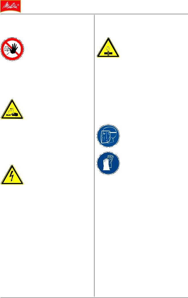
 DANGER
This icon indicates an exceptionally high risk, for example of a life-threatening situation in the event of an electric shock.
 WARNING
This symbol indicates serious hazards such as a risk of injury or destruction of the machine.
 CAUTION
This symbol indicates possible errors and/or damage to the machine.
 INFO
INFO
This symbol indicates important or useful information, such as on the operation of the machine.
Basic safety information
Please observe all safety information in this manual and the user manual.
Maintenance work such as installation, commissioning, servicing, and repair may only be carried out by authorized qualified personnel who have received technical training for the appropriate machine type.
Melitta Cafina CT8 Service Manual V5.0 |
1-3 |
General safety instructions
Securing the work area
Before beginning any work, the work area must be secured so that persons not involved in the work
are not placed at risk. Ensure that persons not involved in the work cannot come in contact with hot
or energized parts or parts carrying steam, or with auxiliary materials such as descalers (acids).
Working with chemicals such as cleaning and descaling agents
Use caution when using cleaning and descaling agents: Read and follow the manufacturer's indica-
tions (safety information sheet,

 instructions for use, labeling) regarding measuring, using, and disposing of these materials. Keep these mate-
rials away from persons not involved in the work. Wear appropriate protective clothing such as safety goggles and protective gloves.
Protection against electrical voltage
Work on the machine must always be conducted by specially trained personnel: Never touch live parts. Ensure that no persons not

 involved in the work can come into contact with any live components. If you must leave an open machine with
live components unattended (even for a brief time), disconnect the machine from the mains and securely reattach all panels and covers which have been removed.
Electrostatic discharge
The machine contains electronic components that are sensitive to electrostatic charge. Ensure that the correct earthing is in place before touching.
Working on the steam system
Work on the steam system is only permitted to be carried out by specially trained personnel:
In the case of improper work on

 components for the steam generator, steam-conveying pipes, or other components, there is a risk of injury due
to scalding. Before carrying out any work on steam-conveying components, ensure that the steam system is vented. The steam boiler must be completely cooled and unpressurized before any work is commenced.
Protective clothing
Protect your health by wearing appropriate protective clothing whenever performing work on the machine.
Face and eye protection
Protective gloves (acid and heat resistant)
Support
Work calmly and carefully. If you have any questions, contact your responsible technical support representative prior to beginning work.
1-4 |
Melitta Cafina CT8 Service Manual V5.0 |
Additional safety instructions
 DANGER
Danger of death
•Never put a damaged unit or a unit with a damaged mains connection cable into operation.
•If you notice any sign of damage (e.g., burning smell), immediately disconnect the unit from the mains supply.
•The unit contains conductive parts. Opening the unit results in risk of death.
 WARNING
Risk of injury and equipment destruction!
•Damaged units are fundamentally unsafe and can cause severe injury or fire.
•Inserting objects in the grinder(s) or other insertion openings on the machine can lead to fragments being ejected from the machine as well as machine malfunctions.
hhDo not insert any objects into the bean container, the chute to the grinder(s), or other insertion openings on the machine.
hhReaching into the machine can result in scrapes or crushing injuries from internal machine components.
•The machine is not protected against large amounts of spray or water jets. hhProtect the unit against water.
hhWhen cleaning the unit, do not use jets of water or high-pressure cleaners.
•Protect the unit from the effects of weather such as rain, frost and direct sunlight. Do not operate the unit outdoors.
•Only use genuine spare parts and accessories. Parts not expressly recommended by Melitta can damage the unit and lead to fire, electric shock, or injury.
 WARNING
Danger of burns!
•The product outlet, the hot water outlet, and the steam pipe become very hot. hhDo not touch the outlets.
•The shelf bases in the cup warmer are hot.
hhDo not touch the shelf bases.
•When products are being dispensed, there is a risk of scalding from the product itself. hhHandle hot drinks carefully.
•A product may be unintentionally dispensed by accidentally touching the product buttons.
hhBe careful only to operate the product buttons intentionally!
•During automatic cleaning as well as cleaning cycles started manually, hot water and hot steam are dispensed repeatedly.
hhKeep hands clear of the outlets during cleaning.
hhIf provided for the machine: Use the splash guard for each cleaning process.
 CAUTION
•Do not empty foreign liquids into the discharge.
Melitta Cafina CT8 Service Manual V5.0 |
1-5 |

1-6 |
Melitta Cafina CT8 Service Manual V5.0 |

Coffee machines & modules
Melitta Cafina CT8 Service Manual V5.0 |
2-1 |

CONTENTS
Coffee machines |
2-3 |
Key |
2-3 |
Modules |
2-4 |
2-2 |
Melitta Cafina CT8 Service Manual V5.0 |
COFFEE MACHINES & MODULES
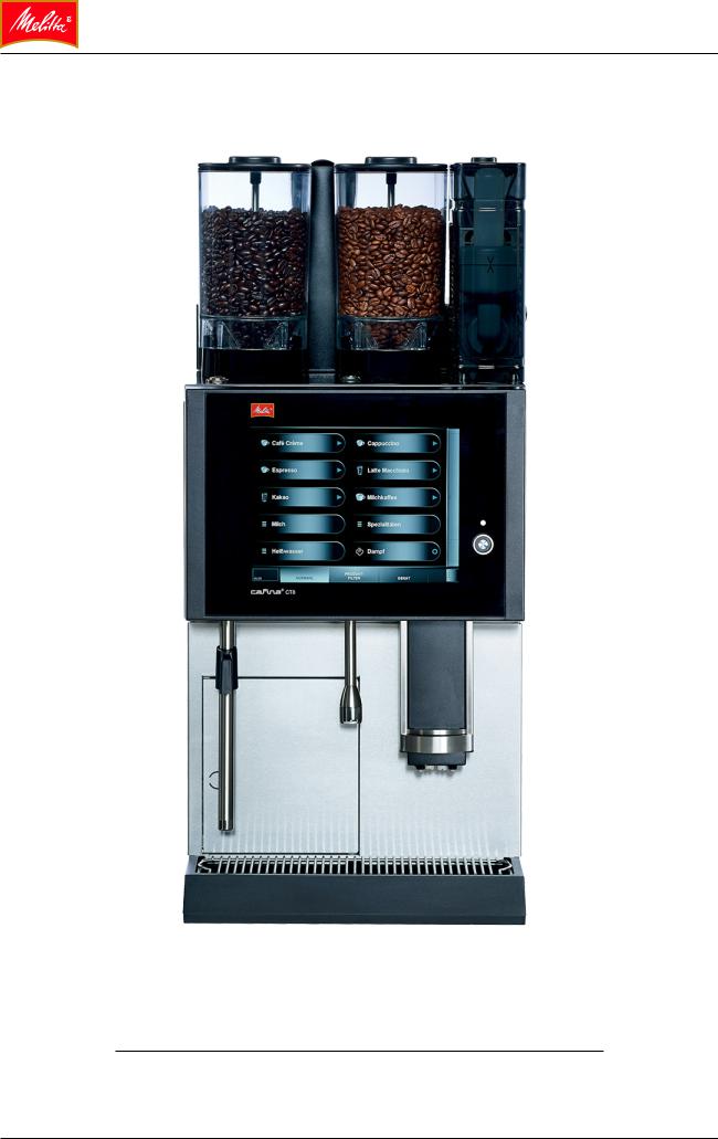
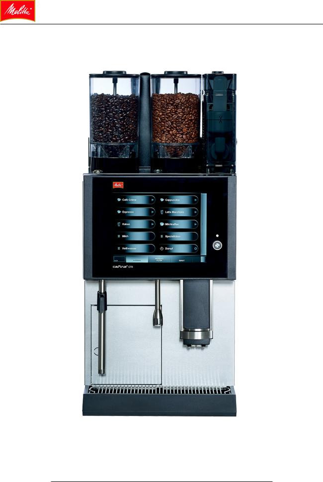
Coffee machines
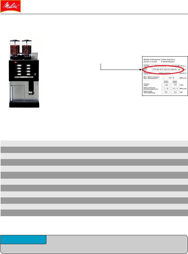
The CT8 coffee machine has a modular design. Information on which modules are included in your model is provided by the type designation on the rating plate.
Melitta Cafina CT8
Key
Example: CT8-2G-2CF-WO-0-0 S0016
Means (according to the nameplate table given below):
CT8 coffee machine with 2 grinders (2G), 2 types of milk (2CF), hotwater from coffee outlet (WO), no steam (0), no instant (0).
0 |
= |
|
|
Placeholder for unavailable options |
1G |
= |
1 |
Grinder |
1 grinder |
2G |
= |
2 |
Grinders |
2 grinders |
1CF |
= |
1 Cold Foam |
Hot and cold milk & milk foam |
|
WO |
= |
Water Outlet |
Hot water from coffee outlet |
|
WW |
= |
Water Wand |
Hot water wand |
|
WA |
= |
Water Adjustable |
Hot water with temperature regulation |
|
SW |
= |
Steam Wand |
Steam wand |
|
1IS |
= |
1 |
Instant |
1 type of instant |
2IS |
= |
2 |
Instants |
2 types of instant |
|
|
|
|
|
|
|
|
|
|
 INFO
INFO
The nameplate is located on the inside of the grounds drawer door.
Melitta Cafina CT8 Service Manual V5.0 |
2-3 |
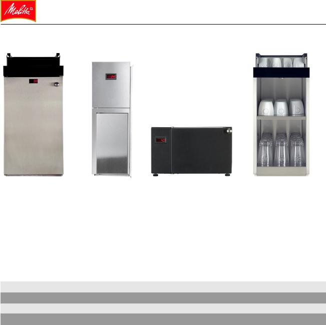
Modules
MC |
MCS |
MCU |
CW |
MC |
= |
Milk cooler |
Cooler |
MCS |
= |
Milk cooler small |
Small cooler |
MCU |
= |
Milk cooler (under unit) |
Milk cooler that fits underneath |
CW |
= |
Cup warmer |
Cup warmer |
2-4 |
Melitta Cafina CT8 Service Manual V5.0 |
Assemblies
Melitta Cafina CT8 Service Manual V5.0 |
3-1 |

CONTENTS
Water supply assemblies |
3-3 |
Steam boiler / coffee boiler |
3-4 |
Piston unit |
3-5 |
Removing the piston unit |
3-5 |
Milk system assemblies |
3-7 |
Milk foam |
3-8 |
Top foam |
3-9 |
Heating the milk / milk foam |
3-10 |
Instant assemblies (with IS option) |
3-11 |
Hot water outlet (HW option) |
3-12 |
Steam dispensing components |
3-12 |
Steam Control Plus (option) |
3-12 |
Valve types used |
3-13 |
Electronic components |
3-15 |
3-2 |
Melitta Cafina CT8 Service Manual V5.0 |
Water supply assemblies |
|
|
The components required for these processes |
|
|
and their functional methods are summarized |
|
|
below. Depending on the machine and its |
|
|
features, the various components may be |
|
|
arranged differently or may not be installed at |
1 |
2 |
all. |
|
|
Rotary vane pump |
|
|
The rotary vane pump [1] is used to supply |
|
|
water and generates the water pressure |
|
|
needed to prepare the coffee. |
|
|
The pump motor is operated with 24 V DC. |
|
|
The pump pressure can be adjusted using the |
|
|
setscrew [2] on the pump's bypass. |
|
|
The pump pressure should be set to 7.5 bar |
|
|
static. The pump pressure is displayed on a |
|
|
0-16 bar pressure gage connected to the CBO. |
|
|
Operating the pump without water or for too |
|
|
long against the closed system can very quickly |
|
3 |
lead to damage to the pump. |
|
|
Flow meter |
|
|
One flow meter [3] measures the water that |
|
|
flows through the coffee boiler. A second flow |
|
|
meter independently measures the water that |
|
|
flows through the cold water block. |
|
|
|
|
|
Melitta Cafina CT8 Service Manual V5.0 |
3-3 |
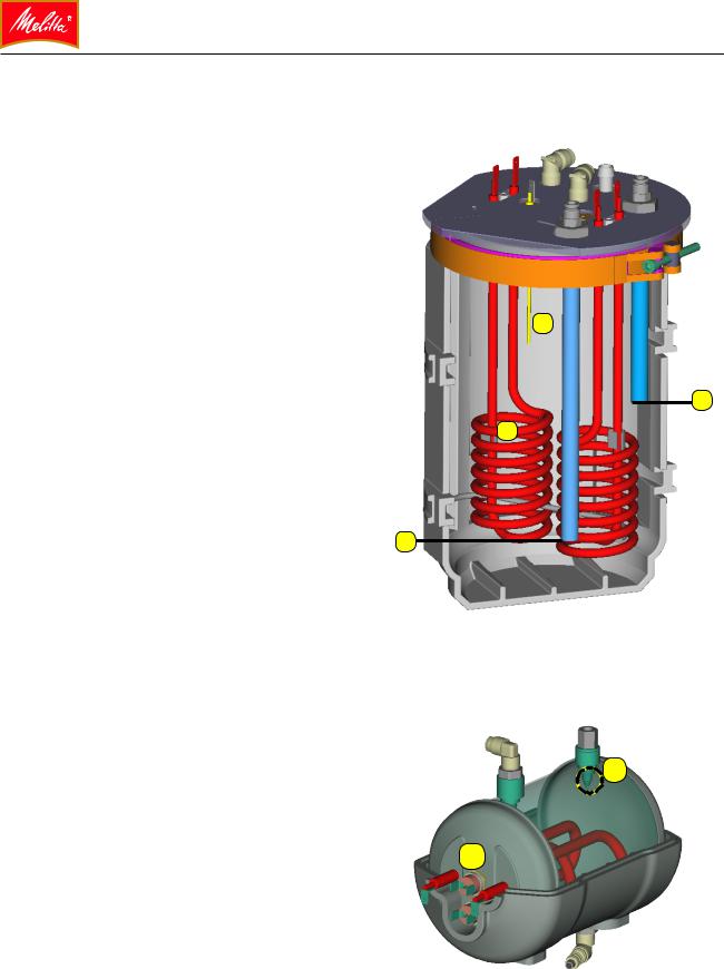
Steam boiler / coffee boiler |
|
|
|
|
|
Depending on the model, the coffee machine |
|
|
|
|
|
may be equipped with a steam boiler (SBO) and |
|
|
|
|
|
a coffee boiler (CBO). The boilers are arranged |
|
|
|
|
|
one above the other inside the coffee machine. |
|
|
|
|
|
SBO (steam boiler) |
|
|
|
|
|
The SBO has a capacity of 4 liters . A sole- |
|
|
|
|
|
noid valve in the cold water block is respon- |
|
|
|
|
|
sible for supplying it with water via a pipe [1]. |
|
|
|
|
|
The pressure is regulated by a pressure sen- |
2 |
|
|
|
|
sor. The fill level is regulated via a level probe |
|
|
|
|
|
[2]. The monitored water level is approximate- |
|
|
|
|
|
ly 2/3 of the SBO capacity. During operation, |
|
|
|
|
|
the steam pressure should be approx. 1.8 |
|
|
|
|
4 |
bar. It can be checked on a pressure gage. |
|
|
|||
3 |
|
|
|
||
|
|
|
|
||
The SBO is equipped with two tubular heating |
|
|
|
|
|
elements [3] located in the bottom third of the |
|
|
|
|
|
boiler. |
|
|
|
|
|
Each tubular heating element is designed for |
|
|
|
|
|
two-phase operation: 2 x 400 V/2800 W. As a |
1 |
|
|
|
|
safety measure, a safety temperature limiter |
|
|
|
|
|
|
|
|
|
||
and a 10 bar pressure-relief valve are used (not |
|
|
|
|
|
pictured here). |
|
|
|
|
|
The hot water is removed from the SBO via an |
|
|
|
|
|
immersion pipe [4]. This is located above the |
|
|
|
|
|
heating element to prevent all the water from |
|
|
|
|
|
being drained away from the heaters. |
|
|
|
|
|
|
6 |
|
|
||
CBO (coffee boiler) |
|
|
|
|
|
The CBO is a flow heater with a capacity |
|
|
|
|
|
of 1.05 liters. As a safety measure, a safety |
5 |
|
|
|
|
temperature limiter [5] and a 10 bar pressure-re- |
|
|
|
||
lief valve are used. The water temperature is |
|
|
|
|
|
recorded by a temperature sensor [6]. |
|
|
|
|
|
|
|
|
|
|
|
|
|
|
|
|
|
3-4 |
Melitta Cafina CT8 Service Manual V5.0 |
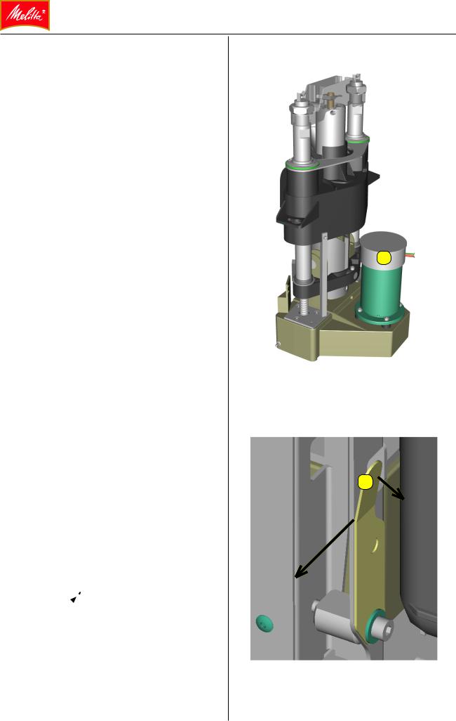
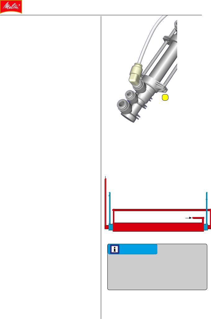
Piston unit
The piston unit assembly features a DC geared motor [1]. The end positions are not monitored by limit switches. The path of the piston unit is controlled via an incremental encoder that can distinguish between left-hand and right-hand rotation.
The slider features a sealing ring. This can be inflated with water pressure to seal the closed brew chamber.
Removing the piston unit
•Disconnect the pipes and electrical connections from the piston unit.
•To remove the piston unit, start by taking off the powder chute.
•Uncouple the hydraulic connections of the piston unit.
•Then remove the central plug connector for the piston motor.
On the left-hand side of the machine:
•Pull the retaining bracket [2] slightly forward.
•Turn the retaining bracket [2] 90° to the left.
The piston unit can now be lifted up and out of the machine.
1
2
Melitta Cafina CT8 Service Manual V5.0 |
3-5 |
Cleaning unit, flushing chamber |
1 |
|
The cleaning unit [1], flushing chamber is new. The customer can open and close this chamber with a lid with bayonet lock. A cleaning tablet is inserted into the chamber during cleaning. Water is fed through the rinsing chamber via valves
Y30 and Y32.
A check valve prevents brewing water from mixing with cleaning water. Remaining water can be sucked out of the rinsing chamber by the vacuum created in the brewing chamber. The rinsing chamber is vented through a check valve for this purpose.
|
|
5 |
Grinders |
2 |
2 |
|
||
The grinders are EK-11 grinders, 230 V with a |
|
4 |
|
5 |
|
14 µF operating capacitor. |
|
|
|
|
|
The grinders are adjusted via DC servomotors |
|
3 |
[2] featuring a worm drive [3]. |
|
Type K30 is also used as the grinder disk pair [4].
There is a guard [5] to prevent accidental contact with the grinder disks.
Grind and grinder output |
|
DC servomotors – ACS |
2 |
The distance between the grinding disks can be altered via servomotors [2] to adjust the fineness of the grind. The grind can be corrected manually during the system calibration process (reference runs) or automatically in dispensing mode.
2
3-6 |
Melitta Cafina CT8 Service Manual V5.0 |
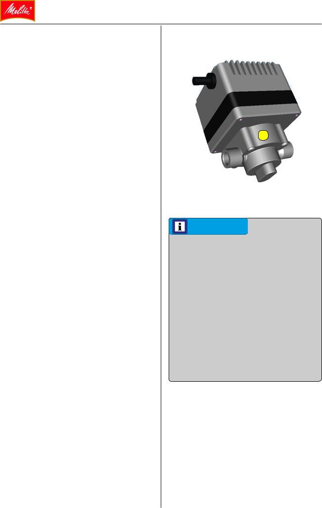
Milk system assemblies
Milk pump functionality
The pump [1] is the heart of the milk system. Using its variable speeds, different delivery rates can be selected so that different pressures and speeds can be achieved in the milk.
•Specifications for the FG109 geared pump:
•Operating voltage / power: approx. 24 V/50 W
•Speed range: approx. 300–5000 rpm
The pump's speed can be set using a control voltage of 0–5 V. It regulates and then maintains the set speed independently until the unit is shut off.
The adjustable speed of the milk pumps enables milk products of various temperatures and consistencies to be created.
Examples:
•Low speed = Thicker foam
•High speed = Finer foam
•Low speed = Hot milk
•High speed = Warm milk
•Top speed = Top foam
1
INFO
Rinsing the milk system
The milk system assemblies are rinsed with cold water via the flushing valve each time milk is drawn. Five milliliters of water are fed to the drain for approx. one second, and then to the outlet (via a diverter valve) for approx. one second.
Cleaning the milk system
A cleaning program passes hot and cold water containing one or more special cleaning agents through the milk system components.
Melitta Cafina CT8 Service Manual V5.0 |
3-7 |
Milk foam |
|
|
|
|
Circular jet nozzle functionality |
|
|
Milk |
|
The circular jet nozzle [2] is used for creating |
|
|
|
|
milk foam. |
|
|
|
|
The circular jet nozzle mixes the milk with air |
|
|
|
|
in the mixing chamber because of its partic- |
2 |
|||
ular geometry. If the air path is closed by the |
|
|
|
|
upstream valve, no foam is produced; instead, |
|
|
|
|
the milk drawn in by the pump is simply |
|
|
|
|
conveyed through the pump. |
Air |
|
|
|
In order to produce foam, a 2/2-way solenoid |
|
|
|
|
|
|
|
|
|
|
|
|
|
|
valve opens the air inlet of the circular jet nozzle. |
|
|
|
|
A 3/2-way valve allows the air inlet path to be |
|
|
|
|
|
|
|
|
|
switched between a fixed nozzle configura- |
|
|
|
|
tion for warm milk foam and an adjustable air |
|
|
Milk or milk foam |
|
restrictor for top foam. |
|
|
||
There is a further solenoid valve for cold milk |
|
|
|
|
foam, as the quantity of air has to be individually |
|
|
|
|
adjusted to create cold milk foam. |
|
|
|
|
INFO |
|
|
|
|
Make sure the circular jet nozzle is inserted |
|
|
|
|
in the correct position. There is a directional |
|
|
|
|
arrow on the outlet side (toward the pump). |
|
|
|
|
The milk/air ratio and therefore the characteristics of the foam can be controlled via the adjustable pump speed. The following principle applies:
•Faster pump speed = More milk + more air
=Finer mixture
•Slower pump speed = Less milk + less air
=Less fine mixture
The air quantity for dense cold milk foam and for top foam must be manually adjusted during installation. This is a one-off operation, which is performed using an associated, infinitely adjust-
able restrictor valve, [1] and [2].
1
2
3-8 |
Melitta Cafina CT8 Service Manual V5.0 |
Top foam
Top foam is a dry, warm milk foam that remains stiff for long periods.
The main purpose of top foam is to enhance the appearance of a coffee beverage such as a cappuccino.
With its temperature of around 45 °C, top foam is cooler than hot milk foam, making the drink more enjoyable. In addition, the layer of top foam stops the coffee from going cold too quickly.
To create top foam, the ideal amount of air must first pass through the circular jet nozzle to create dry, cold milk foam of a good quality. The quantity of air is controlled via the manually adjustable air restrictor.
Once it has been created in this way, the milk foam is heated but instead of being fed to the steam jet nozzle, it is sent through a diverter valve to a heat exchanger (HE) [1]. It is then fed to the outlet via the homogenizer.
Heat exchanger [1] for top foam (TF)
The heat exchanger is made up of a pipe-in- pipe system, in which the steam does not come into direct contact with the milk foam generated.
In order to gently heat the foam, the milk foam is guided through a pipe system heated by steam. No water is able to get into the foam through the steam. As a result, it stays relatively "dry" as well as stable and firm for a long period (several minutes).
The heat exchanger is then rinsed with cold water via valve Y15. There is no nozzle in the cold water line, as a fair amount of rinsing water has to be sent through the heat exchanger.
1
 Steam to the drain
Foam from the circular jet nozzle
Foam to the homogenizer |
Steam valve inlet |
INFO
The pump output is set to 100% in order to create top foam. Reducing the pump output can cause the heat exchanger to overheat. In certain circumstances, milk residue can burn and solidify, meaning that the heat exchanger can no longer be used.
Melitta Cafina CT8 Service Manual V5.0 |
3-9 |
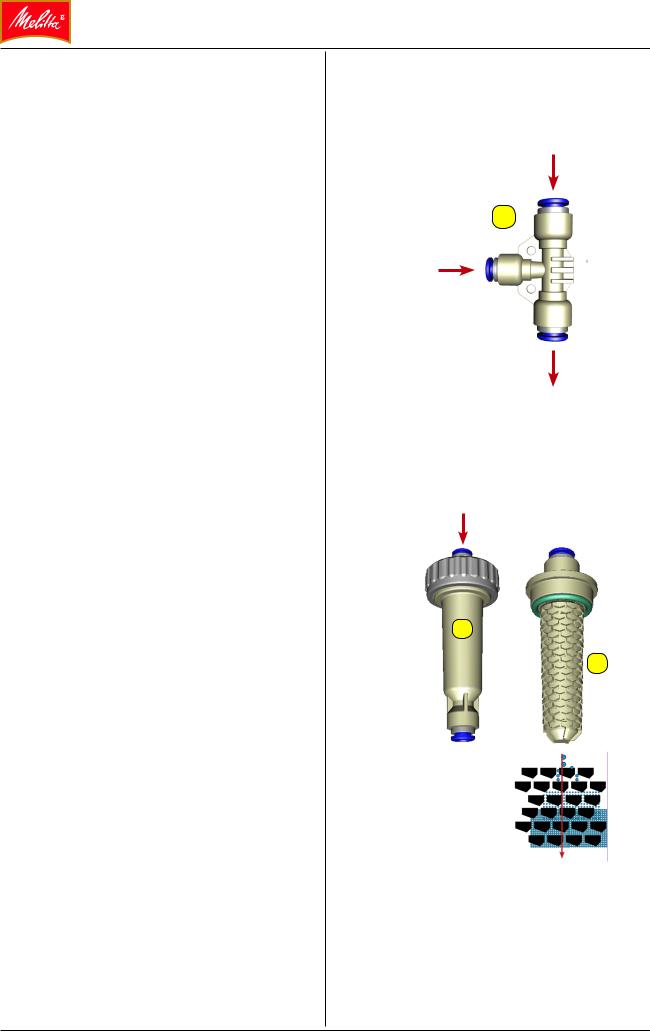
Heating the milk / milk foam
Steam jet nozzle functionality
The milk or milk/air mixture is heated with steam in the steam jet nozzle [3]. Steam is routed as needed to the steam jet nozzle via the steam valve.
The milk/steam ratio and therefore the temperature of the milk or the milk foam can be controlled via the adjustable pump speed.
The following principle applies:
•Faster pump speed = More milk and proportionately less steam = Lower temperature
Too high a pump speed leads to the steam mixing being stopped, meaning that the dispensed milk or milk foam will be cold.
•Lower pump speed = Less milk and proportionately more steam = Higher temperature
Too low a pump speed leads to sputtering at the dispenser or complete shut down of the milk supply so that only steam is dispensed.
Homogenizer functionality
The homogenizer [1] ensures that the bubbles in the milk foam are of a uniform size. This is accomplished by directly the milk foam through fine channels in the homogenizer onto baffles that break the foam bubbles into smaller and smaller bubbles. This ensures uniform, fine foam at the dispenser.
The homogenizer has a very high impact on the quality of the cold milk foam. It plays a minor role in the creation of warm milk foam.
The homogenizer pump speed has an indirect impact on the creation of foam:
•Faster pump speed = Finer milk foam
•Lower pump speed = Less fine milk foam
The product is routed to the height-adjustable outlet by a diversion valve.
Steam
3
Milk/
Milk foam cold
Milk/
Milk foam warm
1
1
3-10 |
Melitta Cafina CT8 Service Manual V5.0 |
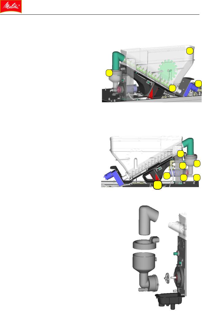
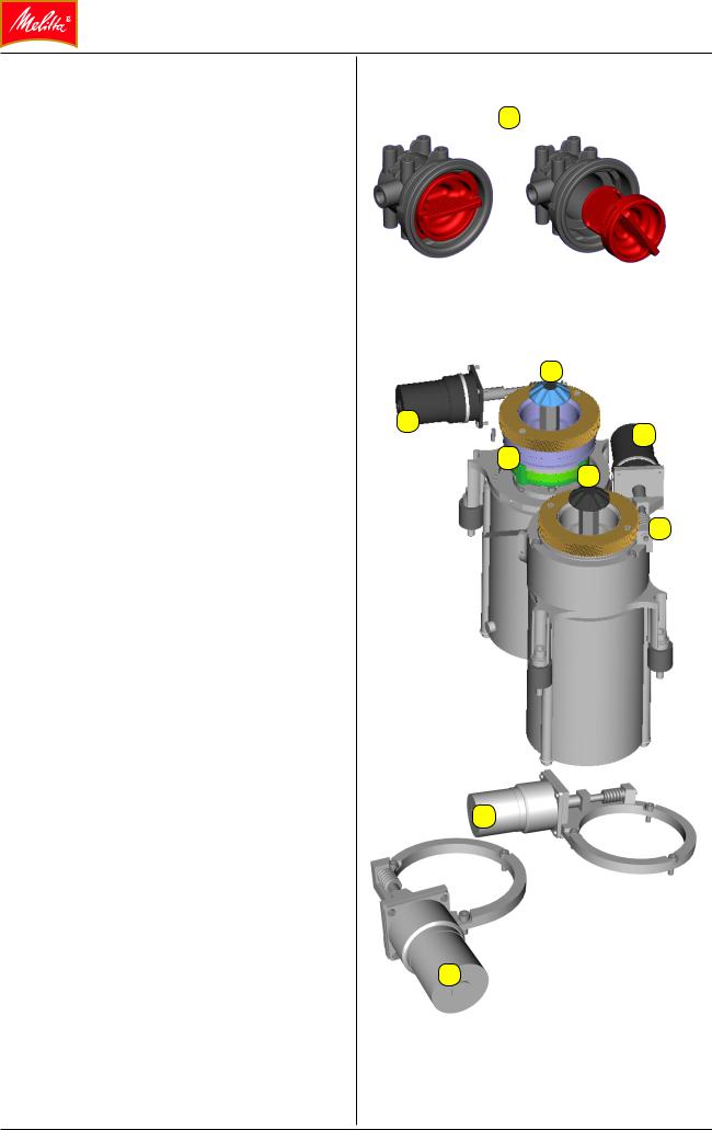
Instant assemblies (with IS option) |
|
|
|
Functional principle |
|
|
|
A geared motor [1] drives a screw feeder [3] |
|
|
2 |
inside the instant container [2] so that the instant |
|
|
|
powder is fed into the mixing chamber [4]. The |
|
|
|
geared motor is speed controlled. This allows |
|
|
|
the amount of instant powder dispensed to be |
4 |
|
|
controlled. |
|
|
|
|
|
3 |
1 |
|
|
|
|
At the same time, hot water is fed into the mixing |
|
|
|
chamber via a solenoid valve and a restrictor [5]. |
|
|
|
The mixer wheel [6] is driven by a speed-con- |
|
|
|
trolled DC motor [7]. Inside the mixing chamber |
|
|
|
[4], the mixer wheel combines the powder with |
|
|
|
hot water by whisking. |
|
|
|
The drink is carried through a line [8] to the |
|
9 |
|
height-adjustable outlet. |
|
|
|
A ventilator [10] draws the water vapor out of |
|
5 |
4 |
|
|
||
the mixing chamber [4] through an extraction |
7 |
|
|
connector [9] to prevent clumps forming. |
6 |
8 |
|
The cover of the instant unit is secured by a |
|
||
10 |
|
|
|
limit switch. If the cover is opened, the machine |
|
|
|
stops dispensing the product and the drive |
|
|
|
motor comes to a standstill. |
|
|
|
The instant containers, mixing chamber, and |
|
|
|
mixer wheel can be removed for cleaning. |
|
|
|
|
|
|
|
Melitta Cafina CT8 Service Manual V5.0 |
3-11 |
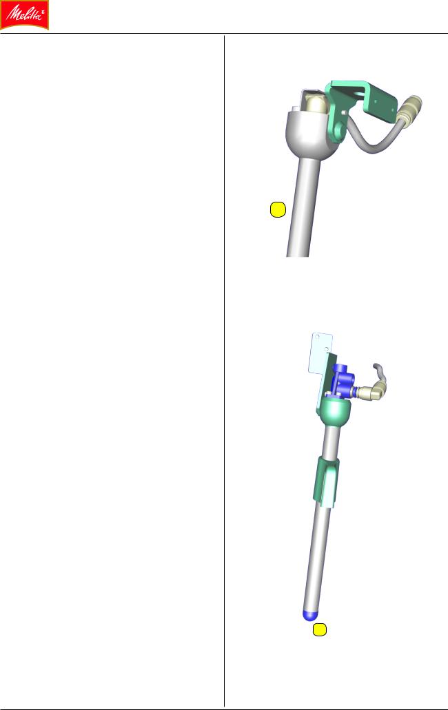
Hot water outlet (HW option)
Hot water output through a separate outlet [1] is optional. The outlet can be swiveled. The water is drawn from the SBO or CBO. Some cold water is mixed in with the hot water to adjust the dispensing temperature.
1
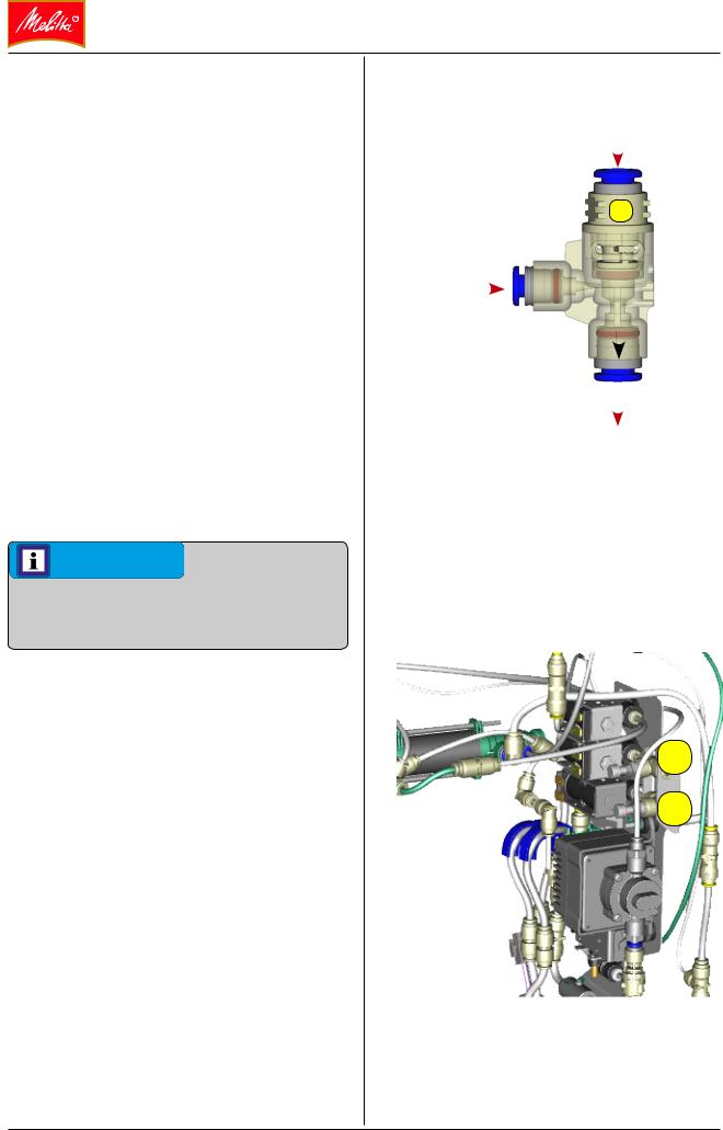
Steam dispensing components
Steam output (option)
Steam can be dispensed from an optional steam outlet through steam output valve Y91. The steam line can be ventilated through the same valve.
Steam Control Plus (option)
The Steam Control lance can be supplied with steam through valve Y91 and valve Y92. To make foam, air can be added to the steam with the familiar air pump.
To manage the automatic frothing process, a temperature sensor [2] is built into the steam lance outlet.
 2
2
3-12 |
Melitta Cafina CT8 Service Manual V5.0 |
Loading...