


AGS 120CM-B
Installation and Maintenance Manual
IMM AGS-2
Air-Cooled Screw Compressor Chiller
AGS 120CS/H - AGS 210CS/H, Packaged
AGS 120CM/B – AHS 210CM/B, Remote Evaporator
60 Hertz, R-134a
Group: Chiller
Part Number: 331373301
Date: July 2008
Supersedes: March 2008
Table of Contents
Introduction.............................................................3
General Description............................................3
Nomenclature.....................................................3
Inspection...........................................................3
Installation and Start-up ..........................................4
Handling.............................................................4
Location .............................................................5
Service Access...................................................5
Clearance Requirements....................................6
Restricted Airflow ...............................................7
Vibration Isolators.............................................13
Chilled Water Pump .........................................19
Water Piping ....................................................19
System Water Volume .....................................20
Variable Speed Pumping..................................20
Evaporator Freeze Protection...........................21
Operating Limits: ..............................................22
Flow Switch ......................................................22
Refrigerant Charge...........................................23
Glycol Solutions ...............................................23
Water Flow and Pressure Drop.............................24
Physical Data, Standard Efficiency .......................26
Physical Data, High Efficiency ..............................27
Dimensional Data .................................................29
Electrical Data ......................................................32
Field Wiring ......................................................32
Field Wiring Diagram ............................................42
BAS Interface ...................................................47
Remote Operator Interface Panel .....................47
Remote Evaporator...............................................48
Manufactured in an ISO Certified Facility
"McQuay" is a registered trademark of McQuay International
Information covers the McQuay International products at the time of publication and we reserve the right
The following are trademarks or registered trademarks of their respective companies: BACnet from ASHRAE; LONM
LONW
to make changes in design and construction at anytime without notice.
ORKS
from Echelon Corporation; GeneSys, McQuay and MicroTech II from McQuay International.
Solid State Starters .............................................. 63
Component Location ............................................ 70
System Maintenance ............................................ 74
Warranty Statement ............................................. 77
Service ................................................................. 77
2004 McQuay International
Piping Layout ................................................... 48
Field Wiring (Remote Evaporator) .................... 49
Kit Components ...............................................49
Refrigerant Line Sizing..................................... 49
Dimensions, Unit with Remote Evaporator ....... 51
Vibration Isolators, Remote Evaporator............58
Physical Data, Standard Efficiency...................60
Physical Data, High Efficiency.......................... 61
Major Component Location .............................. 70
Power Panel..................................................... 72
Control Panel ................................................... 73
General ............................................................ 74
Compressor Maintenance ................................ 74
Lubrication .......................................................74
Electrical Terminals.......................................... 75
Condensers...................................................... 75
Liquid Line Sight Glass .................................... 75
Lead-Lag.......................................................... 76
Preventative Maintenance Schedule ................76
Liquid Line Filter-Driers .................................... 77
Compressor Slide Valves ................................. 78
Electronic Expansion Valve (EXV).................... 78
Evaporator .......................................................79
Charging Refrigerant........................................ 79
Standard Controls ............................................80
Controls, Settings and Functions ..................... 82
Troubleshooting Chart......................................83
Periodic Maintenance Log................................84
Unit controllers are LONM
with an optional LONW
communications module
ARK
ARK and
certified
ORKS
2 IMM AGS-2

Introduction
General Description
McQuay
refrigerating units that include the latest in engineered components arranged to provide a
compact and efficient unit. Each unit is completely assembled, factory wired, evacuated,
charged, tested and comes complete and ready for installation. Each unit consists of two
air-cooled condenser sections with integral subcooler sections, two semi-hermetic, singlescrew compressors with solid-state starters, a two-circuit shell-and-tube direct expansion
evaporator, and complete refrigerant piping. Each compressor has an independent
refrigeration circuit. Liquid line components included are manual liquid line shutoff valves,
charging ports, filter-driers, sight-glass/moisture indicators, solenoid valves and electronic
expansion valves. A discharge shutoff valve is included and a compressor suction shutoff
valve is optional. Other features include compressor heaters, evaporator heaters for freeze
protection, automatic one-time pumpdown of each refrigerant circuit upon circuit
shutdown, and an advanced fully integrated microprocessor control system.
AGS units are divided between standard efficiency (model numbers ending in “0”) and high
efficiency units (ending in “5”). The high efficiency units have certain larger components.
The units are optionally available with the evaporator shipped separately for remote
mounting indoors.
A high ambient option is required for operation in ambient temperatures above 115°F
(46°C), or 105°F (41°C) on units equipped with optional fan VFDs.
Information on the operation of the unit MicroTech II controller is in the OM AGS manual.
GeneSys
air-cooled water chillers are complete, self-contained automatic
Nomenclature
Rotary Screw Compressor
“0” Last Digit=Std. Efficiency
“5” Last Digit=High Efficiency
Air-Cooled
Global
Nominal Tons
A G S - XXX C S
S=Standard Ambient, Packaged Unit
M=Standard Ambient, Remote Evaporator
H=Packaged with High Ambient Option
B=Remote with High Ambient Option.
Design Vintage
Inspection
When the equipment is received, carefully check all items against the bill of lading to check
for a complete shipment. Check all units for damage upon arrival. All shipping damage
must be reported to the carrier and a claim must be filed with the carrier. Check the unit’s
serial plate before unloading the unit to be sure that it agrees with the power supply
available. Physical damage to unit after acceptance is not the responsibility of McQuay
International.
Note: Unit shipping and operating weights are shown in the Physical Data Tables on page
26 for packaged units and page 60 for remote evaporator models.
IMM AGS-2 3
Installation and Start-up
Sharp edges and coil surfaces are a potential injury hazard. Avoid contact with them.
Note: Installation and maintenance are to be performed only by qualified personnel who are
familiar with local codes and regulations, and experienced with this type of equipment.
Start-up by McQuayService is included on all units sold for installation within the USA and
Canada and must be performed by them to initiate the standard limited product warranty.
Two-week prior notification of start-up is required. The contractor should obtain a copy of
the Start-up Scheduled Request Form from the sales representative or from the nearest
office of McQuayService.
Escaping refrigerant can displace air and cause suffocation. Immediately evacuate
and ventilate the equipment area. If the unit is damaged, follow Environmental
Protection Agency (EPA) requirements. Do not expose sparks, arcing equipment, open
flame or other ignition source to the refrigerant.
Handling
Avoid rough handling shock due to impact or dropping the unit. Do not push or pull the
unit.
WARNING
WARNING
Never allow any part of the unit to fall during unloading or moving, as this can result in
serious damage.
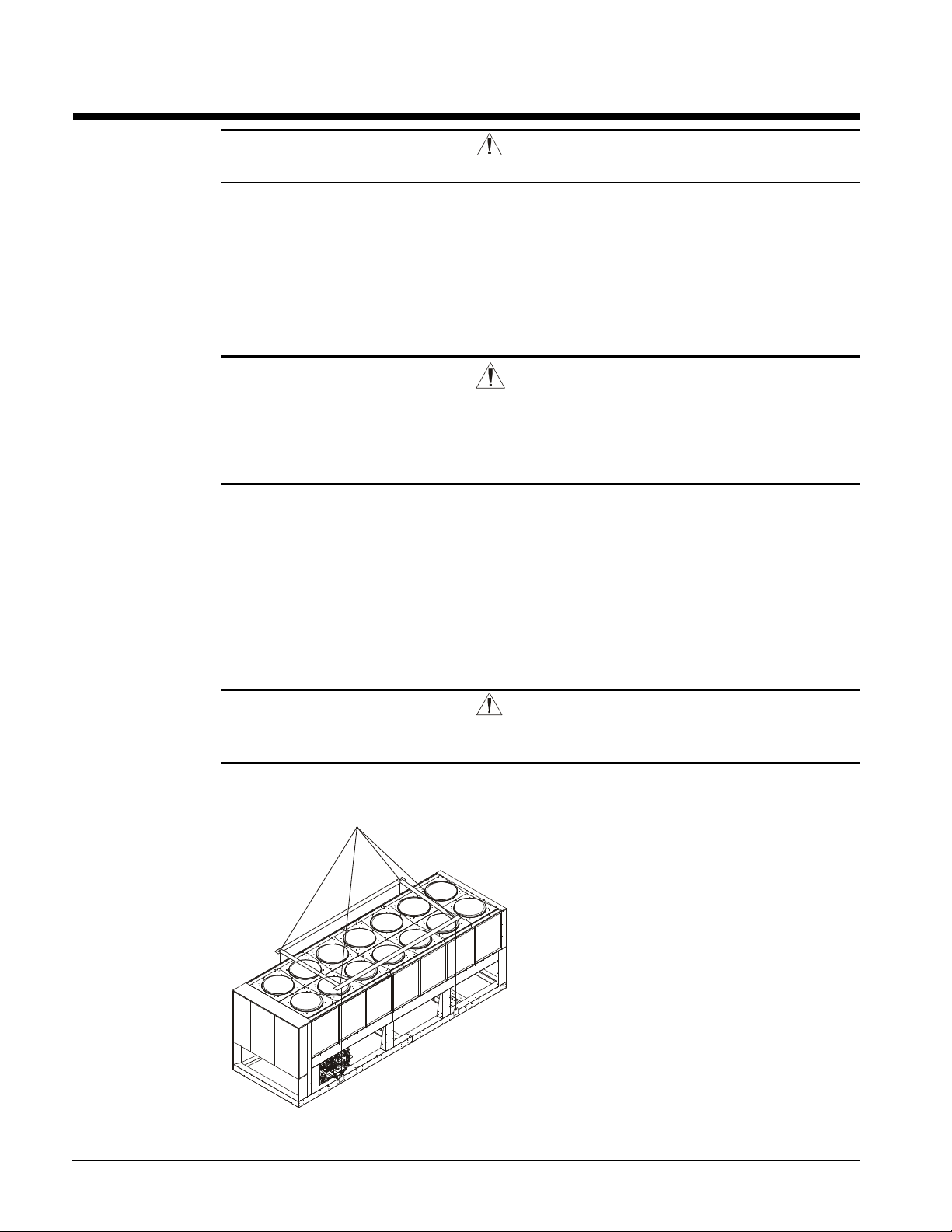
To lift the unit, lifting tabs with 2½" (64 mm) diameter holes are provided on the base of the
unit. All lifting holes must be used when lifting the unit. Spreader bars and cables should
be arranged to prevent damage to the condenser coils or unit cabinet (see Figure 1).
DANGER
Improper lifting or moving unit can result in property damage, severe
personal injury or death. Follow rigging and moving instructions carefully.
Figure 1, Required Lifting Method
NOTES:
1. All rigging points on a unit must be
used. See location and weights at
lifting points beginning on page 13 for a
specific size unit.
2. Crosswise and lengthwise spreader
bars must be used to avoid damage to
unit. Lifting cables from the unit
mounting holes up must be vertical.
3. The number of condenser sections, and
fans can vary from this diagram.
4 IMM AGS-2
Location
Locate the unit carefully to provide proper airflow to the condenser. (See Figure 2 on page
6 for required clearances).
Due to the shape of the condenser coils on the AGS chillers, it is recommended that the unit
be oriented so that prevailing winds blow parallel to the unit length, thus minimizing the
wind effect on condensing pressure and performance. If low ambient temperature operation
is expected, optional louvers should be installed if the unit has no protection against
prevailing winds.
Using less clearance than shown in Figure 2 can cause discharge air recirculation to the
condenser and could have a significant detrimental effect on unit performance.
See Restricted Airflow beginning on page 7 for further information.
For pad-mounted units, it is recommended that the unit be raised a few inches with suitable
supports, located at least under the mounting locations, to allow water to drain from under
the unit and to facilitate cleaning under it
Service Access
Compressors, filter-driers, and manual liquid line shutoff valves are accessible on each side
or end of the unit. The evaporator heater is located on the barrel.
The control panels are located on the end of the chiller. The left-hand control box contains
the unit and circuit microprocessors as well as transformers, fuses and terminal. The righthand panel contains a circuit breaker and solid state starter for each compressor plus fuses,
fan VFD (optional) and fan contactors. A minimum of four feet of clearance is required in
front of the panels.
The side clearance required for airflow provides sufficient service clearance.
On all AGS units, the condenser fans and motors can be removed from the top of the unit.
The complete fan/motor assembly can be removed for service. The fan blade must be
removed for access to wiring terminals at the top of the motor.
WARNING
Disconnect, lockout and tag all power to the unit before servicing condenser fan
motors or compressors.
Failure to do so can cause bodily injury or death.
Do not block access to the sides or ends of the unit with piping or conduit. These areas
must be open for service access. Do not block any access to the control panels with a fieldmounted disconnect switches.
IMM AGS-2 5
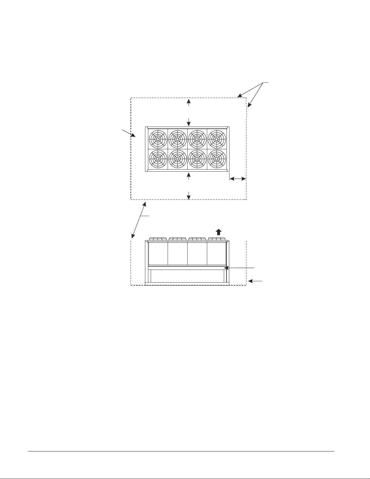
Clearance Requirements
5ft (1.5m)
5ft (1.5m)
3ft (1m) for service
Air Flo
w
No obstructions allowed
above unit at any heigh
t
See notes 2 & 4
concerning wall
height at unit sides.
6ft (1.8m)
6ft (1.8m)
Figure 2, Clearance Requirements, AGS 120C – AGS 210C
if open fence or 50% open wall
if solid wall (see note 3 for pit)
4ft (1.2m)
For electric
panel access
if open fence or 50% open wall
if solid wall (see note 3 for pit)
No obstructions.
Recommended area
required for unit
operation, air flow
and maintenance
access.
See Note 5
Wall or
Fence
Notes:
1. Minimum side clearance between two units is 12 feet (3.7 meters).
2. Unit must not be installed in a pit or enclosure that is deeper or taller than the height of the unit
unless extra clearance is provided per note 4.
3. Minimum clearance on each side is 8 feet (2.4 meters) when installed in a pit no deeper than the
unit height.
4. Minimum side clearance to a side wall or building taller than the unit height is 6 feet (1.8 meters),
provided no solid wall above 6 feet (1.8 meters) is closer than 12 feet (3.7 meters) to the opposite
side of the unit.
5. Do not mount electrical conduits where they can block service access to compressor controls,
refrigerant driers or valves.
6. There must be no obstruction of the fan discharge.
7. Field installed switches must not interfere with service access or airflow.
8. The evaporator can be removed from the side of the unit and may require the temporary removal
of a coil section support post. See dimension drawings beginning on page 29 for details.
9. If the airflow clearances cannot be met, see the following pages on Restricted Airflow.
6 IMM AGS-2
Restricted Airflow
General
The clearances required for design operation of AGS air-cooled condensers are described in
the previous section. Occasionally, these clearances cannot be maintained due to site
restrictions such as units being too close together or a fence or wall restricting airflow, or
both.
The McQuay AGS chillers have several features that can mitigate the problems attributable
to restricted airflow.
• The shape of the condenser section allows inlet air for these coils to come in from both
sides and the bottom. All the coils on one side serve one compressor. Every
compressor always has its own independent refrigerant circuit.
• The MicroTech II control is proactive in response to off-design conditions. In the
case of single or compounded influences restricting airflow to the unit, the
microprocessor will act to keep the compressor(s) running (at reduced capacity) as long
as possible, rather than allowing a shut-off on high discharge pressure.
Figure 3, Coil and Fan Arrangement
The following sections discuss the most common situations of condenser air restriction and
give capacity and power adjustment factors for each. Note that in unusually severe
conditions, the MicroTech II controller will adjust the unit operation to remain online until
a less severe condition is reached.
IMM AGS-2 7
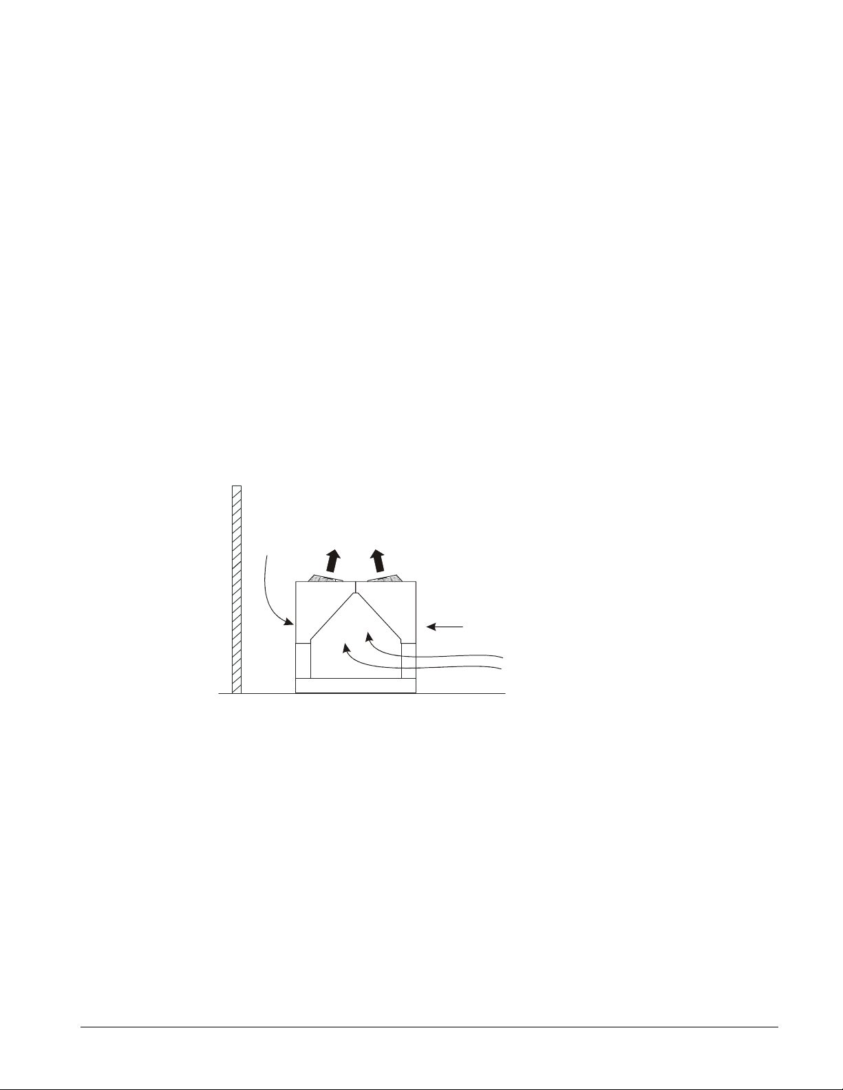
Case 1, Building or Wall on One Side of One Unit
5 ft.
(1.5m)
(1.8m)
The existence of a screening wall, or the wall of a building, in close proximity to an aircooled chiller is common in both rooftop and ground level applications. Hot air
recirculation on the coils adjoining the wall will increase compressor discharge pressure,
decreasing capacity and increasing power consumption.
When close to a wall, it is desirable to place chillers on the north or east side of them. It is
also desirable to have prevailing winds blowing parallel to the unit’s long axis. The worst
case is to have wind blowing hot discharge air into the wall.
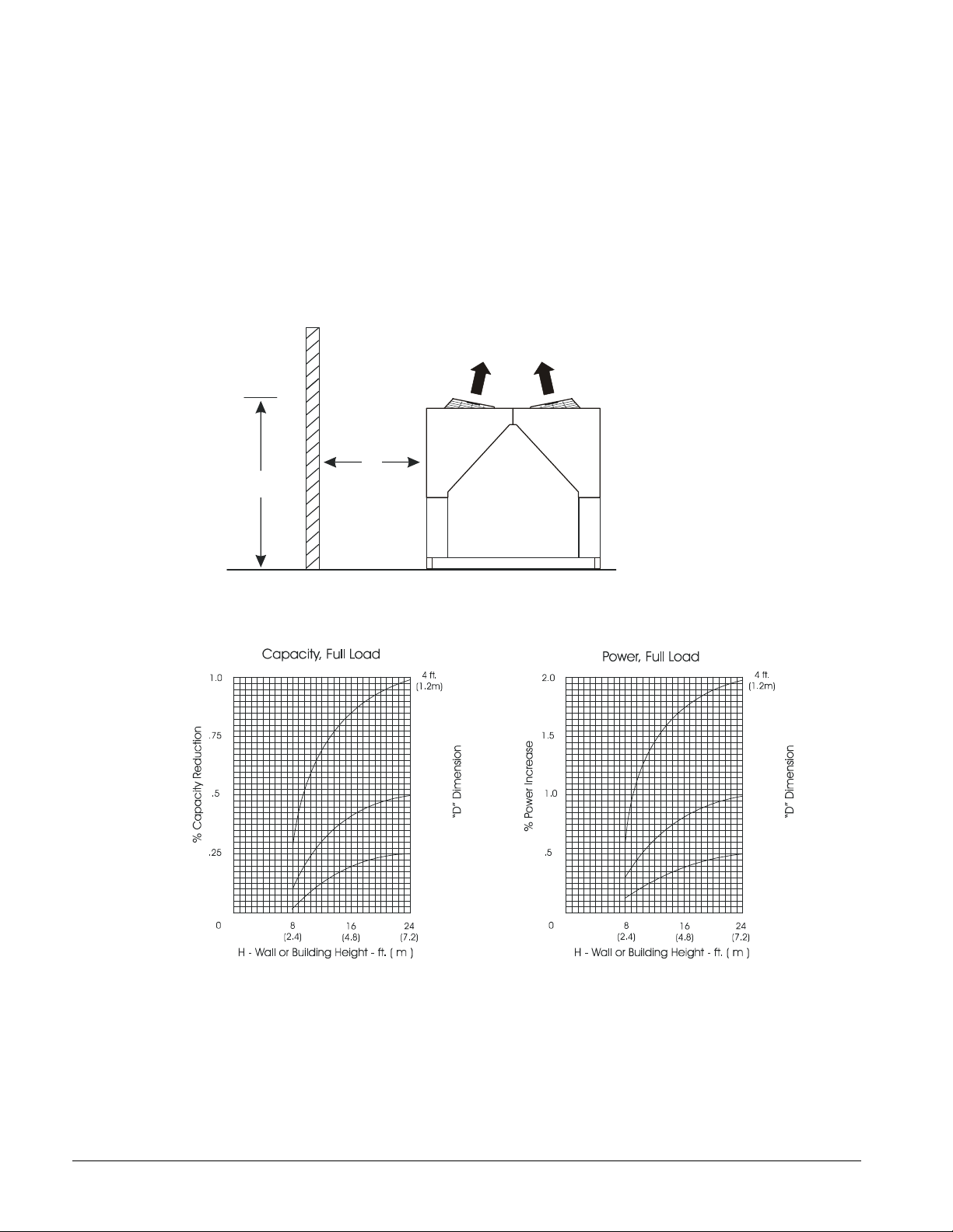
Figure 4, Unit Adjacent to Wall
D
H
Figure 5, Adjustment Factors
(1.5m)
6 ft.
(1.8m)
5 ft.
6 ft.
8 IMM AGS-2
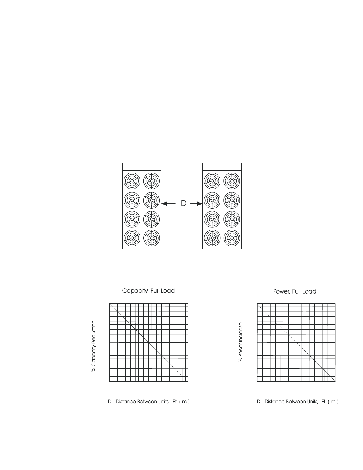
Case 2, Two Units Side By Side
Two or more units sited side by side are common. If spaced closer than 12 feet (3.7 meters), or 8
feet (2.5 meters), depending on size, it is necessary to adjust the performance of each unit.
Circuits adjoining each other are affected. NOTE: This case applies only to two units side by side.
See Case 3 for three or more parallel units. If one of the two units also has a wall adjoining it, see
Case 1. Add the two adjustment factors together and apply to the unit located between the wall
and the other unit.
Mounting units end to end will not necessitate adjusting performance. Depending on the actual
arrangement, sufficient space must be left between the units for access to the control panel door
opening and/or evaporator tube removal. See “Clearance” section of this guide for requirements
for specific units.
Figure 6, Two Units Side by Side
Figure 7, Adjustment Factor
3.0
2.0
1.0
0
9
(2.7)
10
(3.0)
11
(3.3)
12
(3.6)
6.0
4.0
2.0
0
9
(2.7)
10
(3.0)
11
(3.3)
12
(3.6)
IMM AGS-2 9
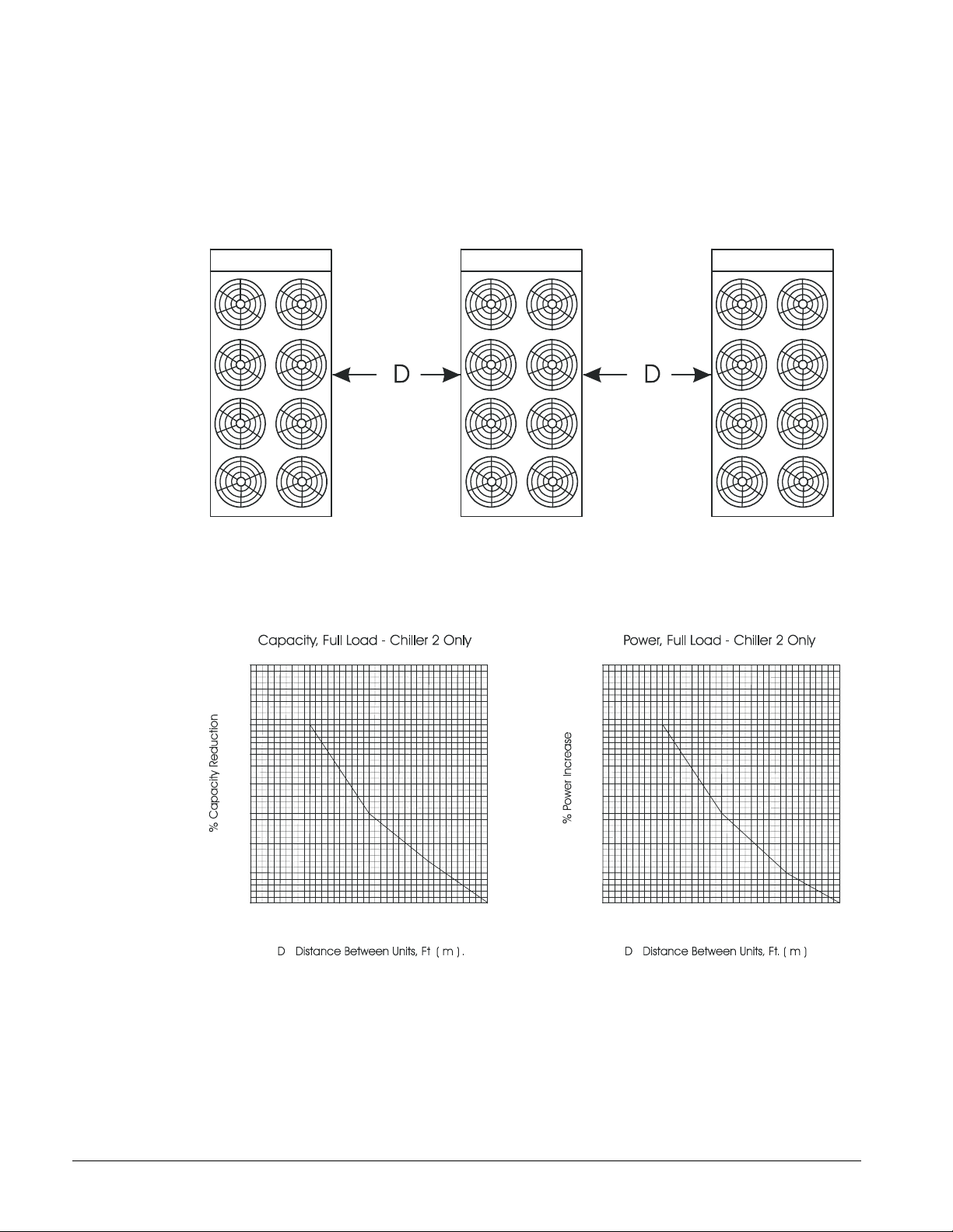
Case 3, Three or More Units Side By Side
When three or more units are side by side, the outside units (chillers 1 and 3 in this case) are
influenced by the middle unit only on their inside circuits. Their adjustment factors will be the
same as Case 2. All inside units (only chiller 2 in this case) are influenced on both sides and must
be adjusted by the factors shown below.
Figure 8, Three or More Units
Chiller 1 Chiller 2 Chiller 3
Figure 9, Adjustment Factor
4.0
3.0
2.0
1.0
0
15
(4.6)
16
(4.9)
17
(5.2)
18
(5.5)
8.0
6.0
4.0
2.0
0
15
(4.6)
16
(4.9)
17
(5.2)
18
(5.5)
10 IMM AGS-2
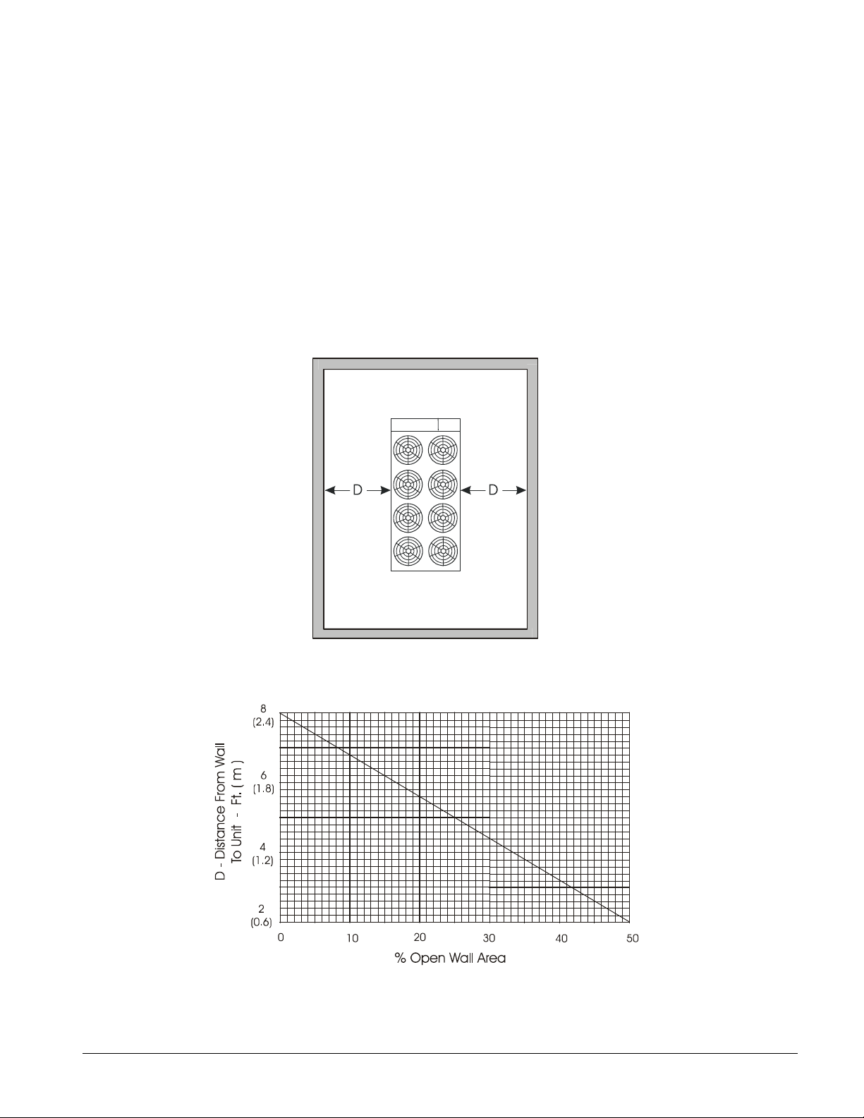
Case 4, Open Screening Walls
Decorative screening walls are often used to help conceal a unit either on grade or on a rooftop.
These walls should be designed such that the combination of their open area and distance from the
unit do not require performance adjustment. It is assumed that the wall height is equal to or less
than the unit height when mounted on its base support. This is usually satisfactory for concealment.
If the wall height is greater than the unit height, see Case 5, Pit Installation.
The distance from the ends of the unit to the end walls must be sufficient for service, opening
control panel doors, and pulling evaporator tubes, as applicable.
If each side wall is a different distance from the unit, the distances can be averaged, providing either
wall is not less than 8 feet (2.4 meters) from the unit. For example, do not average 4 feet and 20
feet to equal 12 feet.
Figure 10, Open Screening Walls
Figure 11, Wall Free Area vs. Distance
IMM AGS-2 11
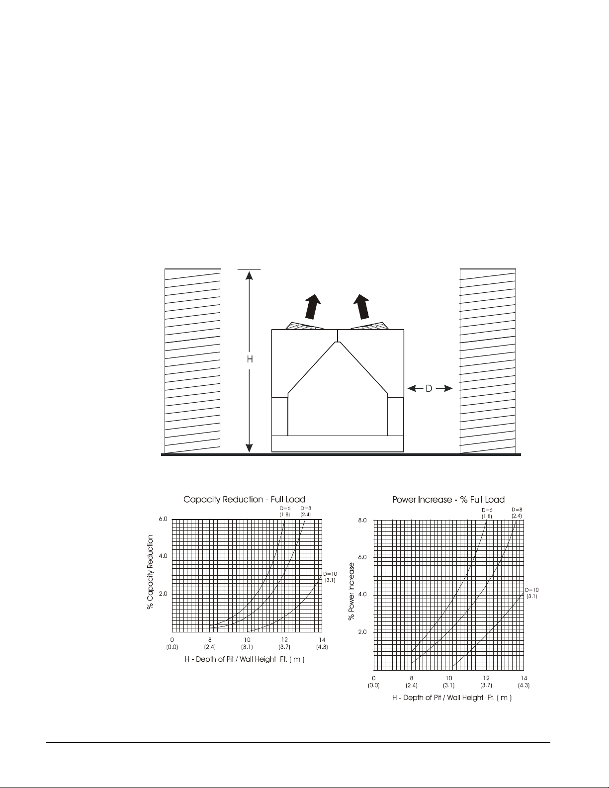
Case 5, Pit/Solid Wall Installation
Pit installations can cause operating problems and great care must be exercised if they are
to be used on an installation. Recirculation and restriction can both occur. A solid wall
surrounding a unit is substantially the same as a pit and the data presented in this case
should be used.
Steel grating is sometimes used to cover a pit to prevent accidental falls or trips into the pit.
The grating material and installation design must be strong enough to prevent such
accidents, yet provide abundant open area or serious recirculation problems will occur.
Have any pit installation reviewed by the McQuay sales office prior to installation to
discuss whether it has sufficient airflow characteristics. The installation design engineer
must approve the work and is responsible for design criteria.
Figure 12, Pit Installation
Figure 13, Adjustment Factor
12 IMM AGS-2
Vibration Isolators
“G”
“E”
“F”
“D”
“C”
“A”
“B”
COG
44.00
“CC”
MM
Vibration isolators are recommended for all roof-mounted installations or wherever vibration
transmission is a consideration. Initially installed the unit on shims or blocks at the illustrated "free
height" of the isolator that is six inches for the McQuay isolators shown. When all piping, wiring,
flushing, charging, etc. is complete, adjust the springs upward to load them and to provide clearance
to free the blocks, which are then removed.
Installation of spring isolators requires flexible pipe connections and at least three feet of conduit
flex tie-ins. Support piping and conduit independently from the unit to not stress connections.
There are separate weight and isolator tables for copper fin coils. All other coil types, such as
ElectroFin and Blackfin, use the aluminum fin data.
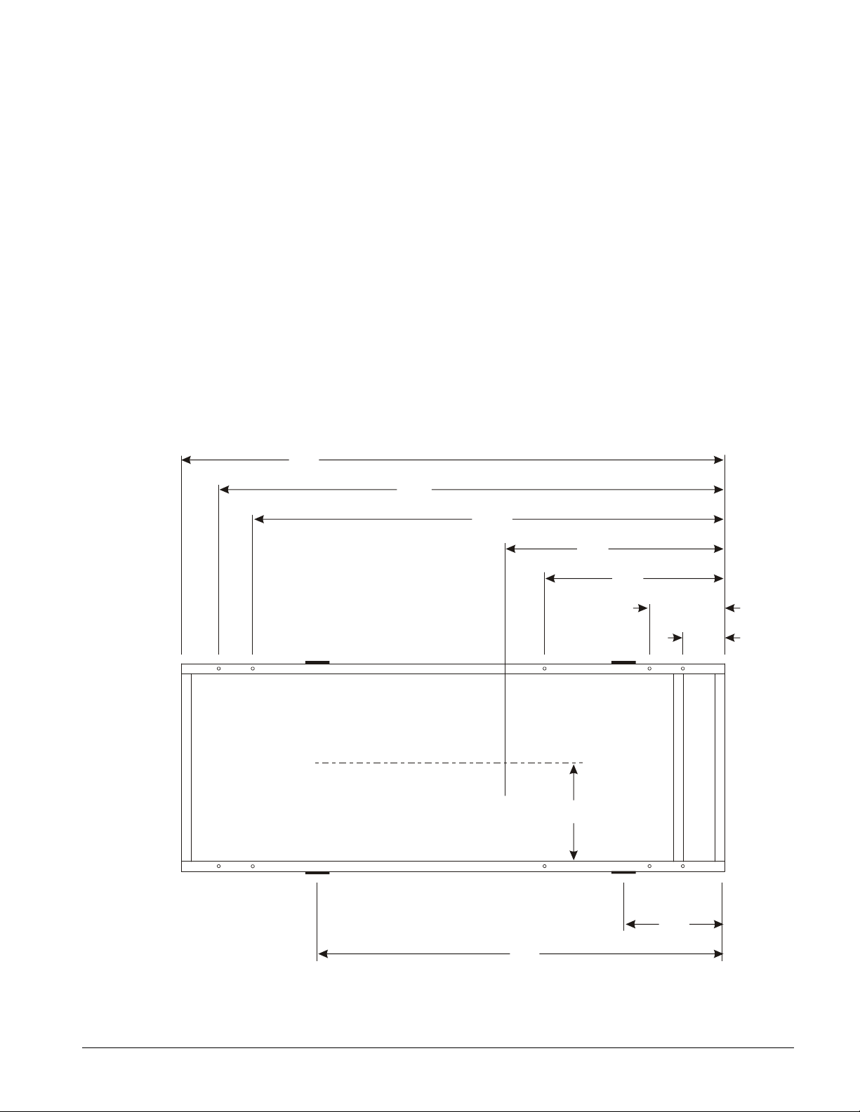
Isolator bolting: the unit base is an enclosed box design and may have six or ten mounting
locations, depending on the date of manufacture. Mounting locations M1 and M2 at dimension “C”
and locations M5 and M6 at dimension “E” are not used. Locations MM1, MM2, M3, M4, MM5
and MM6 have access holes on top of the base, above the lower mounting holes and should be used
for all isolator types. One simple method of bolting the base to the isolators (if required) is to
remove the short threaded studs, usually provided with isolators, and replace them with eight-inch
threaded rod. The rod will extend above the top of the base and a washer and nut can then be easily
attached.
Figure 14, Mounting and Lifting Dimensions
M6
M5
MM5
L3
L4
“EE”
M4
M3
MM2MM6
L2
L1
M2
1
M1
X
O
B
L
O
R
T
N
O
C
330712801D0400_R0A
NOTE: Dimensions are on the following page.
IMM AGS-2 13
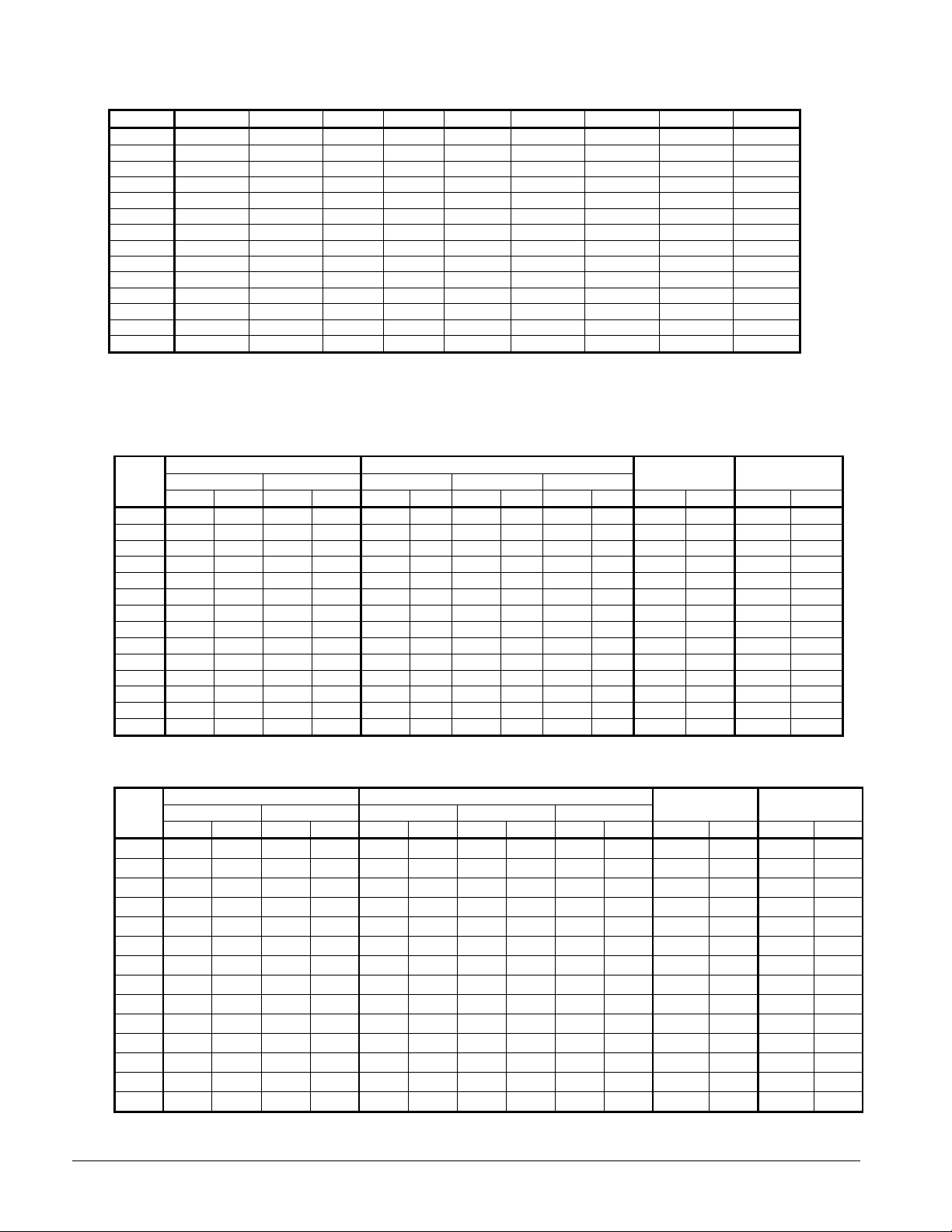
Table 1, Dimensions
MODEL A B C CC D E EE F G
120 36.00 136.60 12.00 21.00 57.30 174.60 165.60 71.49 186.60
125 36.00 168.85 12.00 21.00 69.25 212.80 203.80 86.54 224.80
130 36.00 136.60 12.00 21.00 57.30 174.60 165.60 71.49 186.60
135 36.00 168.85 12.00 21.00 69.25 212.80 203.80 86.54 224.80
140 36.00 136.60 12.00 21.00 57.30 174.60 165.80 71.49 186.60
145 36.00 168.85 12.00 21.00 69.25 212.80 203.80 86.66 224.80
160 36.00 136.60 12.00 21.00 57.30 174.60 165.60 74.37 186.60
165 36.00 189.00 12.00 21.00 84.00 251.00 242.00 105.17 263.00
170 36.00 168.85 12.00 21.00 69.25 212.80 203.80 89.65 224.80
175 36.00 189.00 12.00 21.00 84.00 251.00 242.00 105.17 263.00
180 36.00 168.85 12.00 21.00 69.25 212.80 203.80 89.65 224.80
190 36.00 168.85 12.00 21.00 69.25 212.80 203.80 89.65 224.80
195 36.00 189.00 12.00 21.00 84.00 251.00 242.00 105.17 263.00
210 36.00 189.00 12.00 21.00 84.00 251.00 242.00 105.17 263.00
NOTES:
1. Use location “C”, not “CC”, for mounting.
2. Center of gravity (F) is calculated from shipping weight
3. Dimensions are in inches.
4. Mounting holes are 0.75 inch diameter and have center located 2.0 inches from the outside edge.
Table 2, Lifting and Mounting Weights, Packaged, Aluminum Fins, AGS-CS/H
AGS
120 2919 1324 1591 722 1749 793 1645 746 1333 605 9452 4287 9020 4091
125 3161 1434 1941 880 1996 905 1887 856 1583 718 10930 4958 10205 4629
130 2919 1324 1591 722 1749 793 1645 746 1333 605 9452 4287 9020 4091
135 3161 1434 1941 880 1996 905 1887 856 1583 718 10930 4958 10205 4629
140 2919 1324 1591 722 1749 793 1645 746 1333 605 9452 4287 9020 4091
145 3075 1395 1896 860 1916 869 1810 821 1517 688 10485 4756 9942 4510
160 2933 1330 1809 821 1802 817 1742 790 1561 708 10209 4631 9484 4302
165 3017 1369 2489 1129 2137 969 2038 924 1789 811 11928 5411 11011 4995
170 3269 1483 2007 910 1945 882 1904 864 1790 812 11277 5115 10552 4786
175 3017 1369 2489 1129 2137 969 2038 924 1789 811 11928 5411 11011 4995
180 3269 1483 2007 910 1945 882 1904 864 1790 812 11277 5115 10552 4786
190 3269 1483 2007 910 1945 882 1904 864 1790 812 11277 5115 10552 4786
195 3017 1369 2489 1129 2137 969 2038 924 1789 811 11928 5411 11011 4995
210 3017 1369 2489 1129 2137 969 2038 924 1789 811 11928 5411 11011 4995
Lifting Weights Mounting Weights
L1, L2 L3, L4 MM1, MM2 M3, M4 MM5, MM6
lbs kg lbs kg lbs kg lbs kg lbs kg lbs kg lbs kg
Operating
Weight
Shipping
Weight
Table 3, Lifting and Mounting Weights, Packaged Copper Fins, AGS-CS/H
AGS
120
125
130
135
140
145
160
165
170
175
180
190
195
210
Lifting Weights Mounting Weights
L1, L2 L3, L4 MM1, MM2 M3, M4 MM5, MM6
lbs kg lbs kg lbs kg lbs kg lbs kg lbs kg lbs kg
3557 1613 2229 1011 2174 986 2070 939 1758 798 10728 4866 10296 4670
3959 1796 2739 1242 2528 1147 2419 1097 2115 959 12526 5682 11801 5353
3557 1613 2229 1011 2174 986 2070 939 1758 798 10728 4866 10296 4670
3959 1796 2739 1242 2528 1147 2419 1097 2115 959 12526 5682 11801 5353
3557 1613 2229 1011 2174 986 2070 939 1758 798 10728 4866 10296 4670
3873 1757 2694 1222 2448 1110 2342 1062 2049 929 12081 5480 11538 5234
3571 1620 2447 1110 2227 1010 2167 983 1986 901 11485 5210 10760 4881
3975 1803 3447 1564 2776 1259 2677 1214 2428 1101 13844 6280 12927 5864
4067 1845 2805 1272 2477 1124 2436 1105 2322 1053 12873 5839 12148 5510
3975 1803 3447 1564 2776 1259 2677 1214 2428 1101 13844 6280 12927 5864
4067 1845 2805 1272 2477 1124 2436 1105 2322 1053 12873 5839 12148 5510
4067 1845 2805 1272 2477 1124 2436 1105 2322 1053 12873 5839 12148 5510
3975 1803 3447 1564 2776 1259 2677 1214 2428 1101 13844 6280 12927 5864
3975 1803 3447 1564 2776 1259 2677 1214 2428 1101 13844 6280 12927 5864
Operating
Weight
Shipping
Weight
14 IMM AGS-2
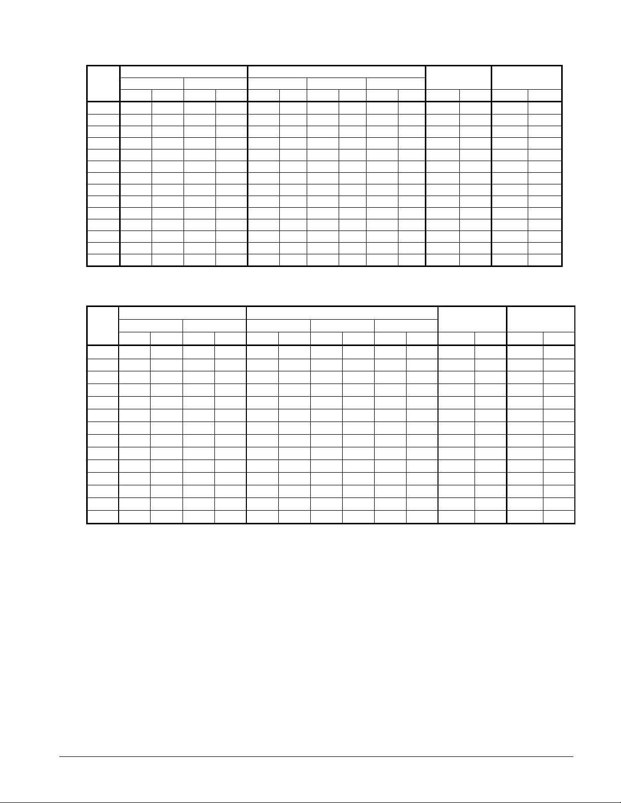
Table 4, Lifting & Mounting Weights, Remote Evaporator, Aluminum Fins, AGS-CM/B
AGS
120
125
130
135
140
145
160
165
170
175
180
190
195
210
Lifting Weights Mounting Weights
L1, L2 L3, L4 MM1, MM2 M3, M4 MM5, MM6
lbs kg lbs kg lbs kg lbs kg lbs kg lbs kg lbs kg
3029 1374 1021 463 1780 807 1521 690 749 340 8100 3674 8100 3674
3169 1437 1307 593 1938 879 1659 753 879 399 8952 4061 8952 4061
3029 1374 1021 463 1780 807 1521 690 749 340 8100 3674 8100 3674
3169 1437 1307 593 1938 879 1659 753 879 399 8952 4061 8952 4061
3029 1374 1021 463 1780 807 1521 690 749 340 8100 3674 8100 3674
3169 1437 1307 593 1938 879 1659 753 879 399 8952 4061 8952 4061
3029 1374 1021 463 1780 807 1521 690 749 340 8100 3674 8100 3674
3196 1450 1590 721 2099 952 1764 800 923 419 9571 4341 9571 4341
3169 1437 1307 593 1938 879 1659 753 879 399 8952 4061 8952 4061
3196 1450 1590 721 2099 952 1764 800 923 419 9571 4341 9571 4341
3169 1437 1307 593 1938 879 1659 753 879 399 8952 4061 8952 4061
3169 1437 1307 593 1938 879 1659 753 879 399 8952 4061 8952 4061
3196 1450 1590 721 2099 952 1764 800 923 419 9571 4341 9571 4341
3196 1450 1590 721 2099 952 1764 800 923 419 9571 4341 9571 4341
Operating
Weight
Shipping
Weight
Table 5, Lifting & Mounting Weights, Remote Evaporator, Copper Fins, AGS-CM/B
AGS
120
125
130
135
140
145
160
165
170
175
180
190
195
210
Lifting Weights Mounting Weights
L1, L2 L3, L4 MM1, MM2 M3, M4 MM5, MM6
lbs kg lbs kg lbs kg lbs kg lbs kg lbs kg lbs kg
3667 1663 1659 753 2205 1000 1946 883 1174 533 9376 4253 9376 4253
3967 1799 2105 955 2470 1120 2191 994 1411 640 10548 4785 10548 4785
3667 1663 1659 753 2205 1000 1946 883 1174 533 9376 4253 9376 4253
3967 1799 2105 955 2470 1120 2191 994 1411 640 10548 4785 10548 4785
3667 1663 1659 753 2205 1000 1946 883 1174 533 9376 4253 9376 4253
3967 1799 2105 955 2470 1120 2191 994 1411 640 10548 4785 10548 4785
3667 1663 1659 753 2205 1000 1946 883 1174 533 9376 4253 9376 4253
4154 1884 2548 1156 2738 1242 2403 1090 1562 708 11487 5211 11487 5211
3967 1799 2105 955 2470 1120 2191 994 1411 640 10548 4785 10548 4785
4154 1884 2548 1156 2738 1242 2403 1090 1562 708 11487 5211 11487 5211
3967 1799 2105 955 2470 1120 2191 994 1411 640 10548 4785 10548 4785
3967 1799 2105 955 2470 1120 2191 994 1411 640 10548 4785 10548 4785
4154 1884 2548 1156 2738 1242 2403 1090 1562 708 11487 5211 11487 5211
4154 1884 2548 1156 2738 1242 2403 1090 1562 708 11487 5211 11487 5211
Operating
Weight
Shipping
Weight
IMM AGS-2 15
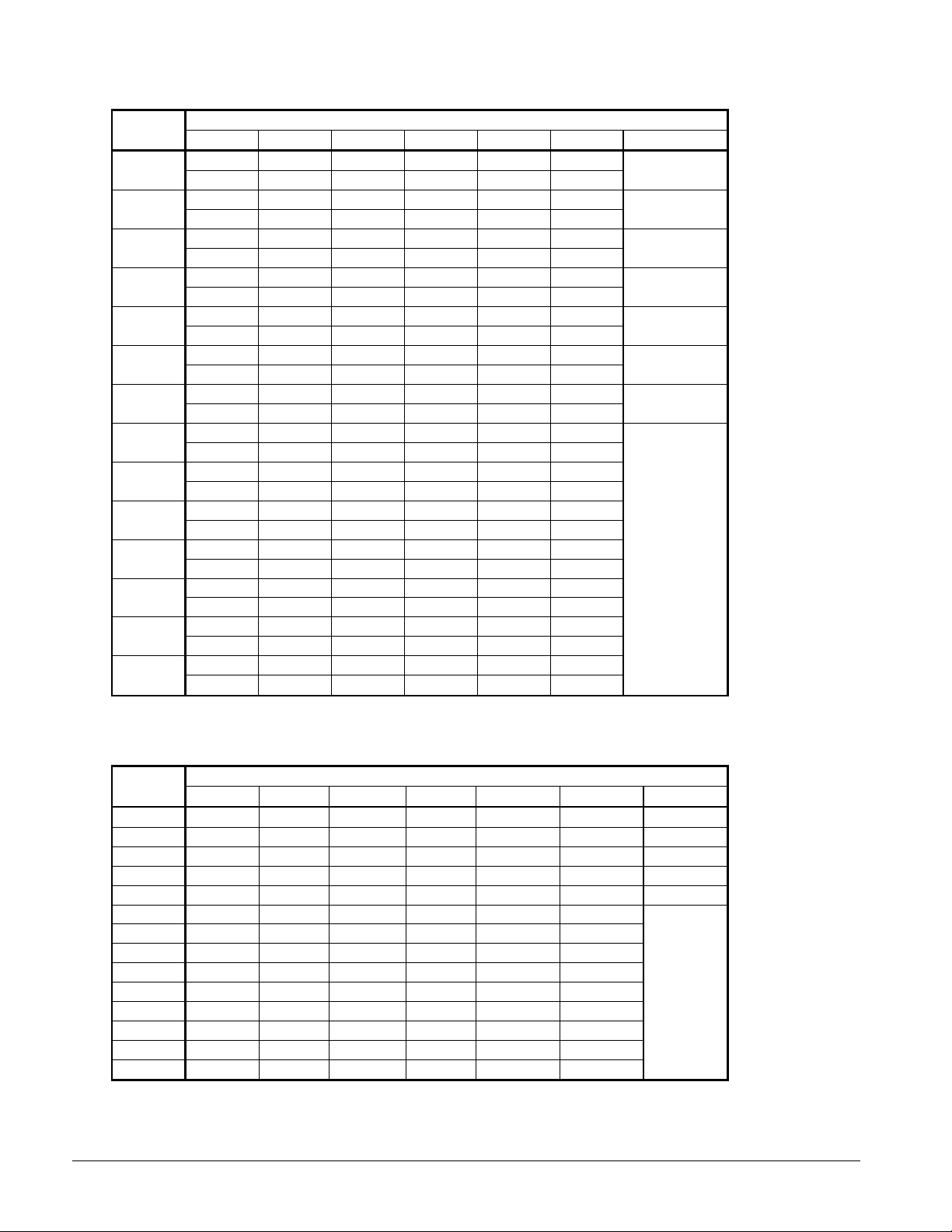
Table 6, Spring Vibration Isolators, Aluminum Fin, AGS-CS/H
AGS
Model
120
125
130
135
140
145
160
165
170
175
180
190
195
210
M1 M2 M3 M4 M5 M6 Kit Number
CP2-28 CP2-28 CP2-28 CP2-28 CP2-27 CP2-27
GREEN GREEN GREEN GREEN ORANGE ORANGE
CP2-31 CP2-31 CP2-31 CP2-31 CP2-28 CP2-28
GRAY GRAY GRAY GRAY GREEN GREEN
CP2-28 CP2-28 CP2-28 CP2-28 CP2-27 CP2-27
GREEN GREEN GREEN GREEN ORANGE ORANGE
CP2-31 CP2-31 CP2-31 CP2-31 CP2-28 CP2-28
GRAY GRAY GRAY GRAY GREEN GREEN
CP2-28 CP2-28 CP2-28 CP2-28 CP2-27 CP2-27
GREEN GREEN GREEN GREEN ORANGE ORANGE
CP2-31 CP2-31 CP2-31 CP2-31 CP2-28 CP2-28
GRAY GRAY GRAY GRAY GREEN GREEN
CP2-28 CP2-28 CP2-28 CP2-28 CP2-28 CP2-28
GREEN GREEN GREEN GREEN GREEN GREEN
CP2-31 CP2-31 CP2-31 CP2-31 CP2-31 CP2-31
GRAY GRAY GRAY GRAY GRAY GRAY
CP2-31 CP2-31 CP2-31 CP2-31 CP2-31 CP2-31
GRAY GRAY GRAY GRAY GRAY GRAY
CP2-31 CP2-31 CP2-31 CP2-31 CP2-31 CP2-31
GRAY GRAY GRAY GRAY GRAY GRAY
CP2-31 CP2-31 CP2-31 CP2-31 CP2-31 CP2-31
GRAY GRAY GRAY GRAY GRAY GRAY
CP2-31 CP2-31 CP2-31 CP2-31 CP2-31 CP2-31
GRAY GRAY GRAY GRAY GRAY GRAY
CP2-31 CP2-31 CP2-31 CP2-31 CP2-31 CP2-31
GRAY GRAY GRAY GRAY GRAY GRAY
CP2-31 CP2-31 CP2-31 CP2-31 CP2-31 CP2-31
GRAY GRAY GRAY GRAY GRAY GRAY
Mounting Location
330904101
330904102
330904101
330904102
330904101
330904102
330904103
330904104
Table 7, Neoprene-in-Shear Isolators, Aluminum Fin, AGS-CS/H
AGS
Model
120
125
130
135
140
145
160
165
170
175
180
190
195
210
M1 M2 M3 M4 M5 M6 Kit Number
RP-4, RED RP-4, RED RP-4, RED RP-4, RED RP-4, BLACK RP-4, BLACK 330904111
RP-4, RED RP-4, RED RP-4, RED RP-4, RED RP-4, RED RP-4, RED 330904112
RP-4, RED RP-4, RED RP-4, RED RP-4, RED RP-4, BLACK RP-4, BLACK 330904111
RP-4, RED RP-4, RED RP-4, RED RP-4, RED RP-4, RED RP-4, RED 330904112
RP-4, RED RP-4, RED RP-4, RED RP-4, RED RP-4, BLACK RP-4, BLACK 330904111
RP-4, RED RP-4, RED RP-4, RED RP-4, RED RP-4, RED RP-4, RED
RP-4, RED RP-4, RED RP-4, RED RP-4, RED RP-4, RED RP-4, RED
RP-4, RED RP-4, RED RP-4, RED RP-4, RED RP-4, RED RP-4, RED
RP-4, RED RP-4, RED RP-4, RED RP-4, RED RP-4, RED RP-4, RED
RP-4, RED RP-4, RED RP-4, RED RP-4, RED RP-4, RED RP-4, RED
RP-4, RED RP-4, RED RP-4, RED RP-4, RED RP-4, RED RP-4, RED
RP-4, RED RP-4, RED RP-4, RED RP-4, RED RP-4, RED RP-4, RED
RP-4, RED RP-4, RED RP-4, RED RP-4, RED RP-4, RED RP-4, RED
RP-4, RED RP-4, RED RP-4, RED RP-4, RED RP-4, RED RP-4, RED
Mounti ng Location ( See Footprint D ra wings, page 13)
330904112
16 IMM AGS-2
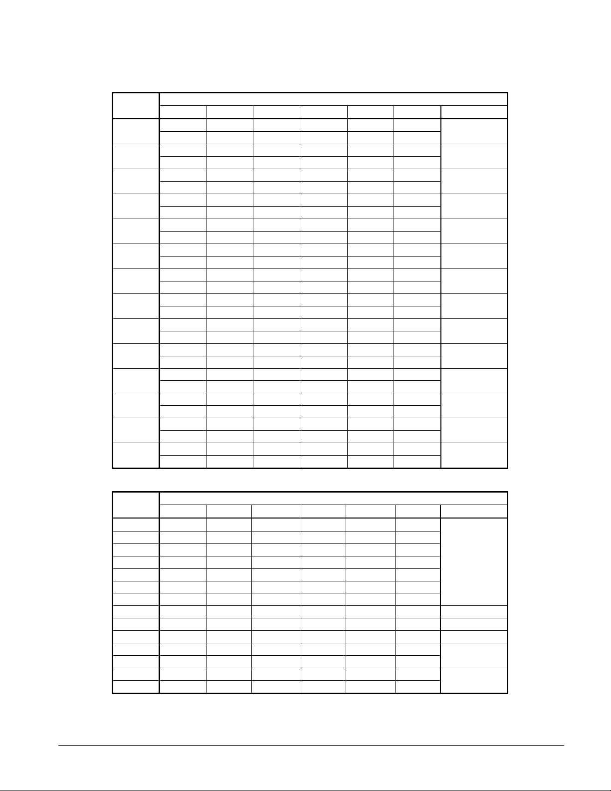
Table 8, Spring Vibration Isolators, Copper Fin, AGS-CS/H
AGS
Model
120
125
130
135
140
145
160
165
170
175
180
190
195
210
M1 M2 M3 M4 M5 M6 Kit Number
CP2-31 CP2-31 CP2-31 CP2-31 CP2-28 CP2-28
GRAY GRAY GRAY GRAY GREEN GREEN
CP2-32 CP2-32 CP2-31 CP2-31 CP2-31 CP2-31
WHITE WHITE GRAY GRAY GRAY GRAY
CP2-31 CP2-31 CP2-31 CP2-31 CP2-28 CP2-28
GRAY GRAY GRAY GRAY GREEN GREEN
CP2-32 CP2-32 CP2-31 CP2-31 CP2-31 CP2-31
WHITE WHITE GRAY GRAY GRAY GRAY
CP2-31 CP2-31 CP2-31 CP2-31 CP2-28 CP2-28
GRAY GRAY GRAY GRAY GREEN GREEN
CP2-31 CP2-31 CP2-31 CP2-31 CP2-31 CP2-31
GRAY GRAY GRAY GRAY GRAY GRAY
CP2-31 CP2-31 CP2-31 CP2-31 CP2-31 CP2-31
GRAY GRAY GRAY GRAY GRAY GRAY
CP2-32 CP2-32 CP2-32 CP2-32 CP2-31 CP2-31
WHITE WHITE WHITE WHITE GRAY GRAY
CP2-32 CP2-32 CP2-31 CP2-31 CP2-31 CP2-31
WHITE WHITE GRAY GRAY GRAY GRAY
CP2-32 CP2-32 CP2-32 CP2-32 CP2-31 CP2-31
WHITE WHITE WHITE WHITE GRAY GRAY
CP2-32 CP2-32 CP2-31 CP2-31 CP2-31 CP2-31
WHITE WHITE GRAY GRAY GRAY GRAY
CP2-32 CP2-32 CP2-31 CP2-31 CP2-31 CP2-31
WHITE WHITE GRAY GRAY GRAY GRAY
CP2-32 CP2-32 CP2-32 CP2-32 CP2-31 CP2-31
WHITE WHITE WHITE WHITE GRAY GRAY
CP2-32 CP2-32 CP2-32 CP2-32 CP2-31 CP2-31
WHITE WHITE WHITE WHITE GRAY GRAY
Mounting Location
330904102
330904105
330904102
330904105
330904102
330904104
330904104
330904106
330904105
330904106
330904105
330904105
330904106
330904106
Table 9, Neoprene-in-Shear Isolators, Copper Fin, AGS-CS/H
AGS
Model
120
125
130
135
140
145
160
165
170
175
180
190
195
210
M1 M2 M3 M4 M5 M6 Kit Number
RP-4, RED RP-4, RED RP-4, RED RP-4, RED RP-4, RED RP-4, RED
RP-4, RED RP-4, RED RP-4, RED RP-4, RED RP-4, RED RP-4, RED
RP-4, RED RP-4, RED RP-4, RED RP-4, RED RP-4, RED RP-4, RED
RP-4, RED RP-4, RED RP-4, RED RP-4, RED RP-4, RED RP-4, RED
RP-4, RED RP-4, RED RP-4, RED RP-4, RED RP-4, RED RP-4, RED
RP-4, RED RP-4, RED RP-4, RED RP-4, RED RP-4, RED RP-4, RED
RP-4, RED RP-4, RED RP-4, RED RP-4, RED RP-4, RED RP-4, RED
RP-4, GRN RP-4, GRN RP-4, GRN RP-4, GRN RP-4, RED RP-4, RED 330904113
RP-4, RED RP-4, RED RP-4, RED RP-4, RED RP-4, RED RP-4, RED 330904112
RP-4, GRN RP-4, GRN RP-4, GRN RP-4, GRN RP-4, RED RP-4, RED 330904113
RP-4, RED RP-4, RED RP-4, RED RP-4, RED RP-4, RED RP-4, RED
RP-4, RED RP-4, RED RP-4, RED RP-4, RED RP-4, RED RP-4, RED
RP-4, GRN RP-4, GRN RP-4, GRN RP-4, GRN RP-4, RED RP-4, RED
RP-4, GRN RP-4, GRN RP-4, GRN RP-4, GRN RP-4, RED RP-4, RED
IMM AGS-2 17
Mounti ng Location ( See Footprint D ra wing, pg. 13)
330904112
330904112
330904113
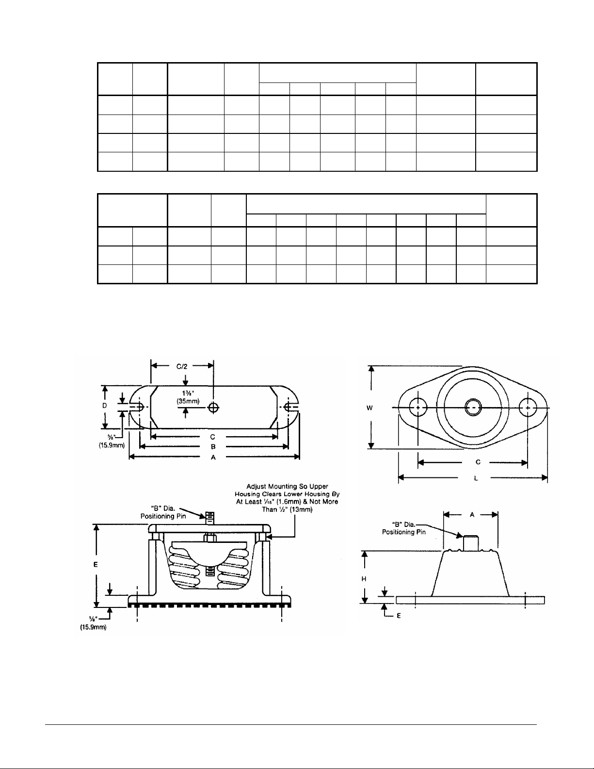
Table 10, Spring Flex Isolators
9.0
(228.6)
9.0
(228.6)
9.0
(228.6)
9.0
(228.6)
Dimensions
In. (mm)
7.7
(195.6)
7.7
(195.6)
7.7
(195.6)
7.7
(195.6)
2.7
(68.6)
2.7
(68.6)
2.7
(68.6)
2.7
(68.6)
5.75
(146.0)
5.75
(146.0)
5.75
(146.0)
5.75
(146.0)
Housing
Part Number
226103B-00 (2) 226117A-00
226103B-00 (2) 226118A-00
226103B-00 (2) 226119A-00
226103B-00 (2) 226120A-00
Spring
Part Number
Housing
CP-2-27 Orange
CP-2-28 Green
CP-2-31 Gray
CP-2-32 White
Spring
Color
Max. Load
Each
Lbs. (kg)
1500
(681)
1800
(815)
2200
(998)
2600
(1180)
Defl.
In. (mm)
0.5
(12.7)
0.5
(12.7)
0.5
(12.7)
0.5
(12.7)
A B C D E
10.2
(259.1)
10.2
(259.1)
10.2
(259.1)
10.2
(259.1)
Table 11, Neoprene-in-Shear Isolators
5.0
5.0
5.0
Dimensions
In. (mm)
0.56
(14.2)
0.56
(14.2)
0.56
(14.2)
0.25
(6.4)
0.25
(6.4)
0.25
(6.4)
1.6
(41.1)
1.6
(41.1)
1.6
(41.1)
6.5
(165.1)
6.5
(165.1)
6.5
(165.1)
4.6
(116.8)
4.6
(116.8)
4.6
(116.8)
McQuay
Part Number
216398A-04
216398A-01
216398A-03
Type
RP-4 Black
RP-4 Red
RP-4 Green
Note (1) "D" is the m ou nt ing hole diam eter.
Max. Load
Each
Lbs. (kg)
1500
(681)
2250
(1019)
3300
(1497)
Defl.
In. (mm)
0.25
(6.4)
0.25
(6.4)
0.25
(6.4)
3.75
(95.3)
3.75
(95.3)
3.75
(95.3)
A B C D (1) E H L W
0.5
(12.7)
(127.0)
0.5
(12.7)
(127.0)
0.5
(12.7)
(127.0)
Figure 15, Spring Flex Mountings Figure 16, Single Neoprene-in-
Shear Mounting
18 IMM AGS-2
Chilled Water Pump
It is recommended that the chilled water pumps' starters be wired to, and controlled by, the
chiller's microprocessor. The controller will energize the pump whenever at least one
circuit on the chiller is enabled to run, whether there is a call for cooling or not. Wiring
connection points are shown in Figure 23 on page 42.
Water Piping
Due to the variety of piping practices, follow the recommendations of local authorities.
They can supply the installer with the proper building and safety codes required for a
proper installation.
Design the piping with a minimum number of bends and changes in elevation to keep
system cost down and performance up. It should contain:
1. Vibration eliminators to reduce vibration and noise transmission to the building.
2. Shutoff valves to isolate the unit from the piping system during unit servicing.
3. Manual or automatic air vent valves at the high points of the system and drains at the
low parts in the system. The evaporator should not be the highest point in the piping
system.
4. Some means of maintaining adequate system water pressure (i.e., expansion tank or
regulating valve).
5. Water temperature and pressure indicators located at the evaporator inlet and outlet to
aid in unit servicing. Any connections should be made prior to filling the system with
water.
6. A strainer to remove foreign matter from the water before it enters the pump. Place the
strainer far enough upstream to prevent cavitation at the pump inlet (consult pump
manufacturer for recommendations). The use of a strainer will prolong pump life and
help maintain high system performance levels.
NOTE
the inlet of the evaporator. This will aid in preventing foreign material from entering
the evaporator and causing damage or decreasing its performance. Care must also be
exercised if welding pipe or flanges to the evaporator connections to prevent any weld
slag from entering the vessel.
7. Any water piping to the unit must be protected to prevent freeze-up if below freezing
temperatures are expected.
:
A 40 mesh strainer must also be placed in the supply water line just prior to
CAUTION
If a separate disconnect is used for the 115V supply to the unit, it should power the
entire control circuit, not just the evaporator heaters. It should be clearly marked
so that it is not accidentally shut off during cold seasons. Freeze damage to the
evaporator could result. If the evaporator is drained for winter freeze protection,
the heaters must be de-energized to prevent burnout.
8. If the unit is used as a replacement chiller on a previously existing piping system, flush
the system thoroughly prior to unit installation. Perform regular chilled water analysis
and chemical water treatment immediately at equipment start-up.
IMM AGS-2 19

9. In the event glycol is added to the water system as a late addition for freeze protection,
recognize that the refrigerant suction pressure will be lower, cooling performance less,
and water side pressure drop greater. If the percentage of glycol is large, or if
propylene is employed in lieu of ethylene glycol, the added pressure drop and loss of
performance could be substantial.
10. For ice making or low temperature glycol operation, a different freezestat pressure
value is usually required. The freezestat setting can be manually changed through the
MicroTech II controller.
Make a preliminary leak check prior to insulating the water piping and filling the system.
Include a vapor barrier with the piping insulation to prevent moisture condensation and
possible damage to the building structure. It is important to have the vapor barrier on the
outside of the insulation to prevent condensation within the insulation on the cold surface
of the pipe.
System Water Volume
It is important to have adequate water volume in the system to provide an opportunity for
the chiller to sense a load change, adjust to the change and stabilize. As the expected load
change becomes more rapid, a greater water volume is needed. The system water volume is
the total amount of water in the evaporator, air handling products and chilled water piping.
If the water volume is too low, operational problems can occur including rapid compressor
cycling, rapid loading and unloading of compressors, erratic refrigerant flow in the chiller,
improper motor cooling, shortened equipment life and other undesirable consequences.
For normal comfort cooling applications where the cooling load changes relatively slowly, a
minimum system volume of three minutes times the flow rate (gpm) is recommend. For
example, if the design chiller flow rate is 400 gpm, we recommend a minimum total system
volume of 1200 gallons (400 gpm x 3 minutes).
For process applications, such as a quenching tank, where the cooling load can change
rapidly, additional system water volume is needed. The load would be very stable until the
hot material is immersed in the water tank. Then, the load would increase drastically. For
this type of application, system volume can need to be increased.
Since there are many other factors that can influence performance, systems can successfully
operate below these suggestions. However, as the water volume decreases below these
suggestions, the possibility of problems increases.
Variable Speed Pumping
Variable water flow involves reducing the water flow through the evaporator as the load
decreases. McQuay chillers are designed for this duty, provided that the rate of change in
water flow is slow, and the minimum and maximum flow rates for the vessel are not
exceeded.
The recommended maximum change in water flow is 10 percent of the change per minute.
The water flow through the vessel must remain between the minimum and maximum values
listed on page 25. If flow drops below the minimum allowable, large reductions in heat
transfer can occur. If the flow exceeds the maximum rate, excessive pressure drop and tube
erosion can occur.
20 IMM AGS-2
Evaporator Freeze Protection
AGS chillers are equipped with thermostatically controlled evaporator heaters that help
protect against freeze-up down to -20°F (-28°C).
NOTE: The heaters come from the factory connected to the control power circuit. The
control power can be rewired in the field to a separate 115V supply (do not wire directly to
the heater). See the field wiring diagram on page 42. If this is done, mark the disconnect
switch clearly to avoid accidental deactivation of the heater during freezing temperatures.
Exposed chilled water piping also requires protection.
For additional protection, at least one of the following procedures should be used during
periods of sub-freezing temperatures:
1. Adding of a concentration of a glycol anti-freeze with a freeze point 10 degrees F below
the lowest expected temperature. This will result in decreased capacity and increased
pressure drop.
Note: Do not use automotive grade antifreezes as they contain inhibitors harmful to
chilled water systems. Use only glycols specifically designated for use in building
cooling systems.
2. Draining the water from outdoor equipment and piping and blowing the chiller tubes
dry from the chiller. Do not energize the chiller heater when water is drained from the
vessel.
CAUTION
If fluid is absent from the evaporator, the evaporator heater must be de-energized
to avoid burning out the heater and causing damage from the high temperatures.
1. Providing operation of the chilled water pump, circulating water through the chilled
water system and through the evaporator.
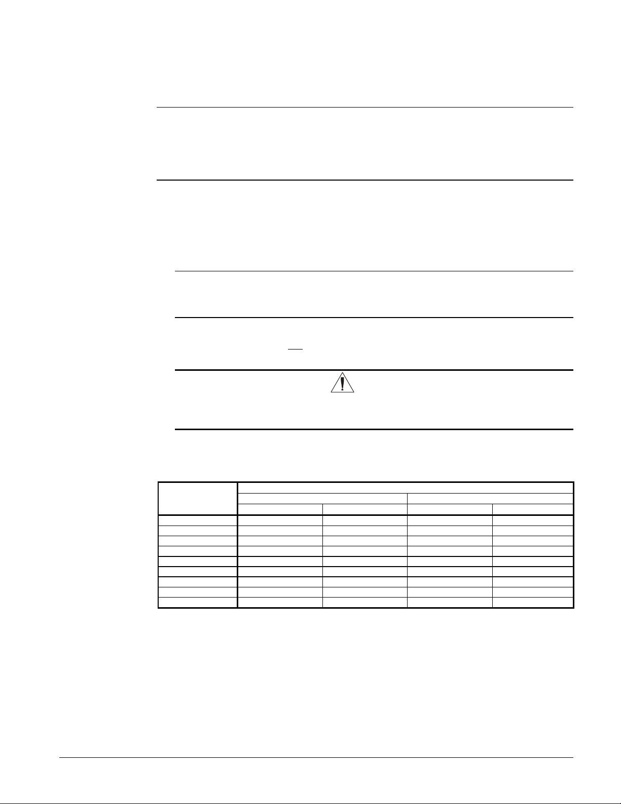
Table 12, Freeze Protection
Temperature
°°°°F (°°°°C)
20 (6.7) 16 18 11 12
10 (-12.2) 25 29 17 20
0 (-17.8) 33 36 22 24
-10 (-23.3) 39 42 26 28
-20 (-28.9) 44 46 30 30
-30 (-34.4) 48 50 30 33
-40 (-40.0) 52 54 30 35
-50 (-45.6) 56 57 30 35
-60 (-51.1) 60 60 30 35
Notes:
1. These figures are examples only and cannot be appropriate to every situation. Generally, for an extended margin of
protection, select a temperature at least 15°F lower than the expected lowest ambient temperature. Inhibitor levels
should be adjusted for solutions less than 25% glycol.
2. Glycol of less than 25% concentration is not recommended because of the potential for bacterial growth and loss of
heat transfer efficiency.
For Freeze Protection For Burst Protection
Ethylene Glycol Propylene Glycol Ethylene Glycol Propylene Glycol
Percent Volume Glycol Concentration Required
IMM AGS-2 21
Operating Limits:
Maximum standby ambient temperature, 130°F (55°C)
Maximum operating ambient temperature, see below
Minimum operating ambient temperature (standard), 35°F (2°C)
Minimum operating ambient temperature (optional low-ambient control), 0°F (-18°C)
Leaving chilled water temperature, 40°F to 60°F (4°C to 16°C)
Leaving chilled fluid range (with anti-freeze), 20°F to 60°F (-7°C to 16°C). Unloading is
not permitted with fluid leaving temperatures below 30°F (-1°C).
Operating Delta-T range, 6 degrees F to 16 degrees F (10.8 C to 28.8 C)
Maximum operating inlet fluid temperature, 76°F (24°C)
Maximum startup inlet fluid temperature, 90°F (32°C)
Maximum non-operating inlet fluid temperature, 100°F (38°C)
NOTE: Contact the local McQuay sales office for operation outside any of these limits.
Maximum Operating Ambient Temperatures
Standard Efficiency, designated by a "0" as the last digit in the model number (such as
AGS 170C) are designed for operation up to 125 degrees. Significant unloading above 115
degrees can occur depending on a variety of factors. Contact your sales representative for
performance above 115 degrees. Additional unloading can result with leaving water
temperatures above 45 degrees.
High Efficiency, designated by a "5" as the last digit in the model number (such as AGS
175C) are designed for operation up to 125 degrees without unloading for leaving water
temperatures between 40 and 45 degrees Fahrenheit. Contact your sales representative for
evaporator duty outside of this range. The High Efficiency models have larger components,
and/or more fans than the comparable Standard Efficiency models. This results in
improved efficiency and the ability to operate at higher ambient air temperatures.
High Ambient Option, A factory-installed option that provides components allowing
operation in high ambient temperature locations. It can be applied to any unit and is
mandatory on:
1. All units with the optional VFD low ambient control.
2. All units that can have operating ambient temperatures above 115°F (46°C).
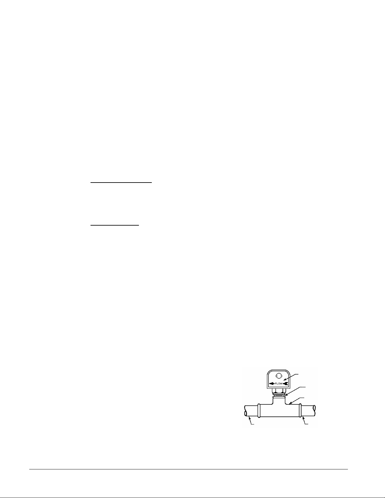
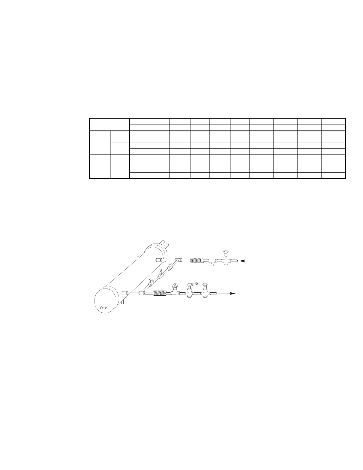
Flow Switch
A flow switch must be included in the
chilled water system to prove that there is
adequate water flow to the evaporator
before the unit can start. It also serves to
shut down the unit in the event that water
flow is interrupted in order to guard
against evaporator freeze-up.
A solid state flow switch that is factorymounted and wired in the chiller leaving
water nozzle is available as an option.
A flow switch for field mounting and
wiring in the leaving chilled water is also
available as an option from McQuay under
22 IMM AGS-2
Figure 17, Flow Switch
1 1/4" (32mm) pipe
dia. min. after switch
Flow direction marked
on switch
1" (25mm) NPT flow
switch connection
Tee
1 1/4" (32mm) pipe
dia. min. before switch
ordering number 017503300. It is a paddle-type switch and adaptable to any pipe size from
Vent
Valve
Vibration
Valved
Against Freezing
Vibration
Valve
Valve
1" (25mm) to 8" (203mm) nominal.
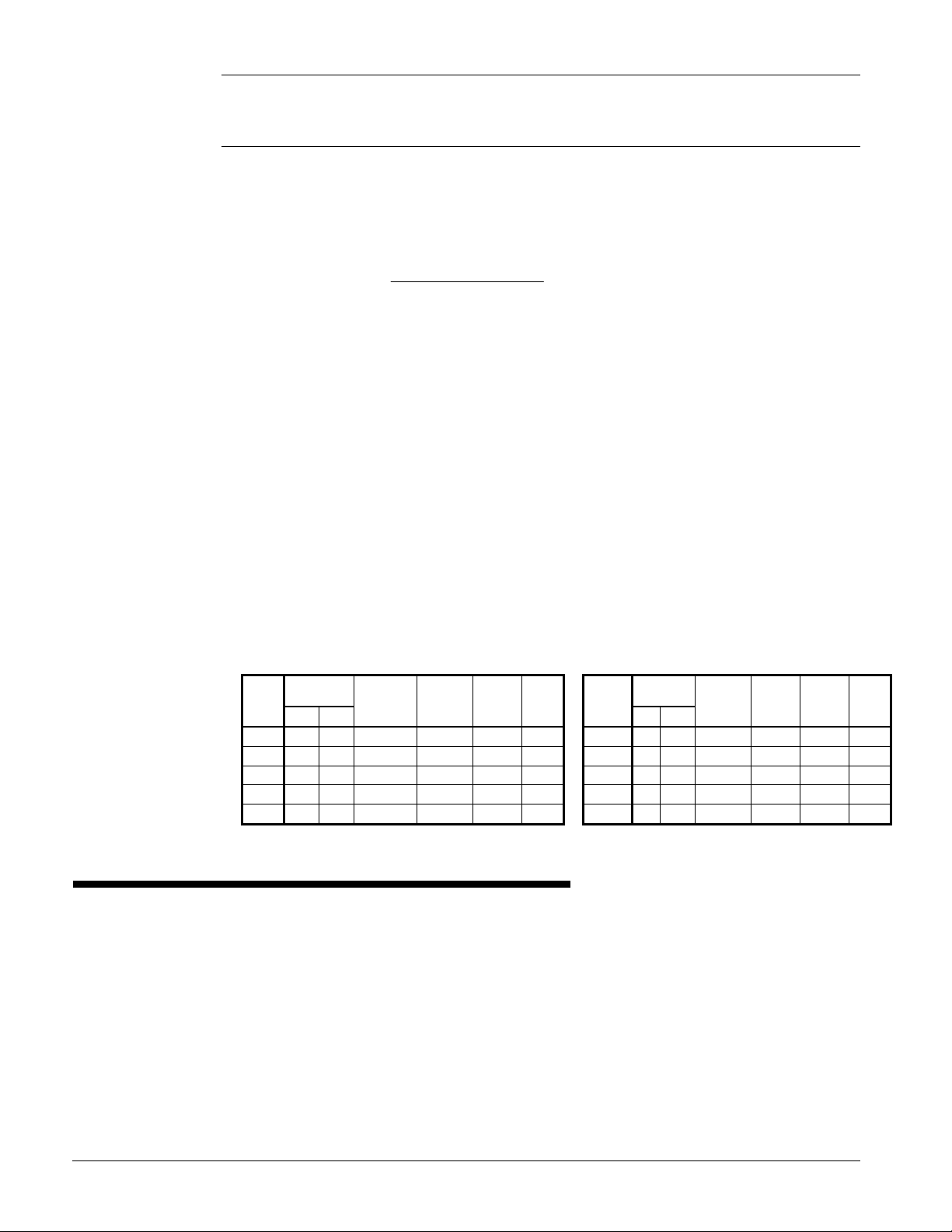
Certain minimum flow rates are required to close the switch and are listed in Table 13.
Installation should be as shown in Figure 18.
Electrical connections in the unit control center should be made at terminals 60 and 67 from
switch terminals Y and R. The normally open contacts of the flow switch should be wired
between these two terminals. Flow switch contact quality must be suitable for 24 VAC, low
current (16ma). Flow switch wire must be in separate conduit from any high voltage
conductors (115 VAC and higher) and have an insulation rating of 600 volts.
Table 13, Flow Switch Flow Rates
(NOTE !)
Min.
Adjst.
Max.
Adjst.
Flow
Flow Lpm 0.8 1.1 2.2 2.8 4.3 11.4 22.9 35.9 38.6
Flow
Flow Lpm 2.8 4.1 6.1 7.3 11.4 27.7 53.4 81.8 90.8
NOTES:
1. A segmented 3-inch paddle (1, 2, and 3 inches) is furnished mounted, plus a 6-inch paddle loose.
2. Flow rates for a 2-inch paddle trimmed to fit the pipe.
3. Flow rates for a 3-inch paddle trimmed to fit the pipe.
4. Flow rates for a 3-inch paddle.
5. Flow rates for a 6-inch paddle.
inch 1 1/4 1 1/2 2 2 1/2 3 4 5 6 8 Pipe Size
mm 32 (2) 38 (2) 51 63 (3) 76 102 (4) 127 (4) 153 (4) 204 (5)
gpm 5.8 7.5 13.7 18.0 27.5 65.0 125.0 190.0 205.0
Lpm 1.3 1.7 3.1 4.1 6.2 14.8 28.4 43.2 46.6
gpm 3.7 5.0 9.5 12.5 19.0 50.0 101.0 158.0 170.0
No
gpm 13.3 19.2 29.0 34.5 53.0 128.0 245.0 375.0 415.0
Lpm 3.0 4.4 6.6 7.8 12.0 29.1 55.6 85.2 94.3
gpm 12.5 18.0 27.0 32.0 50.0 122.0 235.0 360.0 400.0
No
Figure 18, Typical Field Water Piping
Suction
In
Gauge
Flow
Eliminator
Balancing
Pressure
Out
Liquid
Drain
Notes:
1. Connections for vent and drain fittings are located on the top and bottom of the evaporator.
2. Piping must be supported to avoid putting strain on the evaporator nozzles.
Eliminator
Switch
Water
Strainer
Gate
Flow
Gate
Protect All Field Piping
Flow
Refrigerant Charge
All packaged units are designed for use with R-134a and are shipped with a full operating
charge. The operating charge for each unit is shown in the Physical Data Tables beginning
on page 26 for packaged units, and page 60 for remote evaporator models. Model AGSCM/CB with remote evaporators are shipped with a full unit charge. Refrigerant must be
added in the field for the evaporator and for the refrigerant lines.
Glycol Solutions
When using glycol anti-freeze solutions the chiller's capacity, glycol solution flow rate, and
pressure drop through the evaporator can be calculated using the following formulas and
tables.
IMM AGS-2 23
Note: The procedure below does not specify the type of glycol. Use the derate factors
()()(
)
found in Table 14 for corrections when using propylene glycol and those in Table 15 for
ethylene glycol.
1. Capacity - Cooling capacity is reduced from that with plain water. To find the
reduced value, multiply the chiller’s water system tonnage by the capacity correction
factor to find the chiller’s capacity when using glycol.
2. Flow - To determine flow (or Delta-T) knowing Delta-T (or flow) and capacity:
GPM−=
24
factorflowtons
TDelta
3. Pressure drop - To determine pressure drop through the evaporator when using
glycol, enter the water pressure drop curve at the water flow rate. Multiply the water
pressure drop found there by the "PD" factor to obtain corrected glycol pressure drop.
4. Power - To determine glycol system kW, multiply the water system kW by the factor
designated "Power".
Test coolant with a clean, accurate glycol solution hydrometer (similar to that found in
service stations) to determine the freezing point. Obtain percent glycol from the freezing
point table below. On glycol applications, the supplier normally recommends that a
minimum of 25% solution by weight be used for protection against corrosion or that
additional inhibitors should be employed.
NOTE: Do not use automotive grade antifreeze. Industrial grade glycols must be used.
Automotive antifreeze contains inhibitors that will cause plating on the copper tubes within
the chiller evaporator. The type and handling of glycol used must be consistent with local
codes.
Table 14, Ethylene Glycol Factors
Freeze
%
E.G.
Point
oF o
26 -3.3 0.996 0.998 1.036 1.097
10
18 -7.8 0.988 0.994 1.061 1.219
20
7 -13.9 0.979 0.991 1.092 1.352
30
-7 -21.7 0.969 0.986 1.132 1.532
40
-28 -33.3 0.958 0.981 1.182 1.748
50
Capacity Power Flow PD
C
Table 15, Propylene Glycol Factors
Freeze
% P.G.
10
20
30
40
50
Point
oF o
26 -3.3 0.991 0.996 1.016 1.092
19 -7.2 0.981 0.991 1.032 1.195
9 -12.8 0.966 0.985 1.056 1.345
-5 -20.6 0.947 0.977 1.092 1.544
-27 -32.8 0.932 0.969 1.140 1.906
Capacity Power Flow PD
C
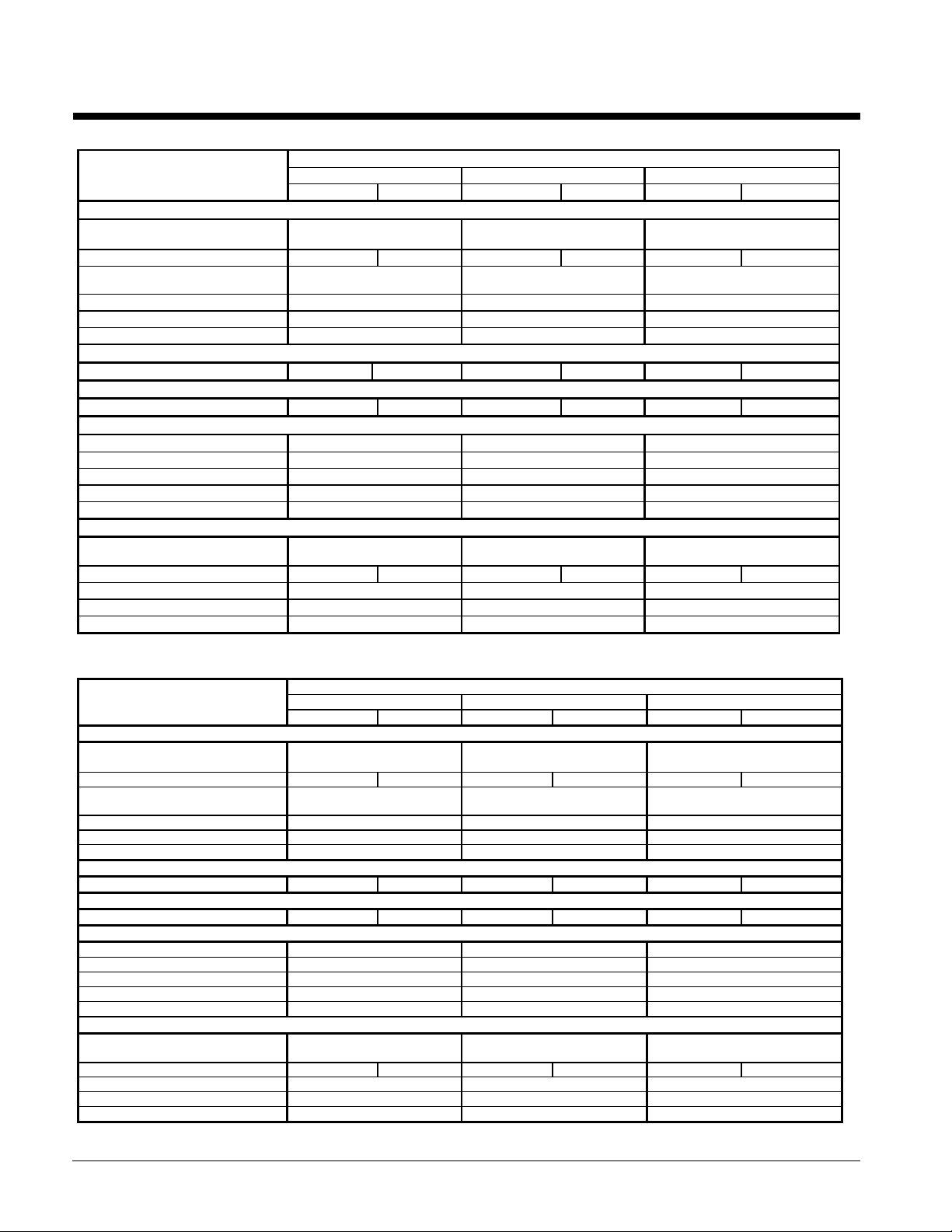
Water Flow and Pressure Drop
Adjust the chilled water flow through the evaporator to meet specified conditions. The
flow rates must fall between the minimum and maximum values shown in the table on the
following page. Flow rates below the minimum values shown will result in laminar flow
that will reduce efficiency, cause erratic operation of the electronic expansion valve and
could cause low temperature cutouts. On the other hand, flow rates exceeding the
maximum values shown can cause erosion on the evaporator water connections and tubes.
Measure the chilled water pressure drop through the evaporator at field-installed pressure
taps. It is important not to include valve or strainer pressure drops in these readings.
24 IMM AGS-2
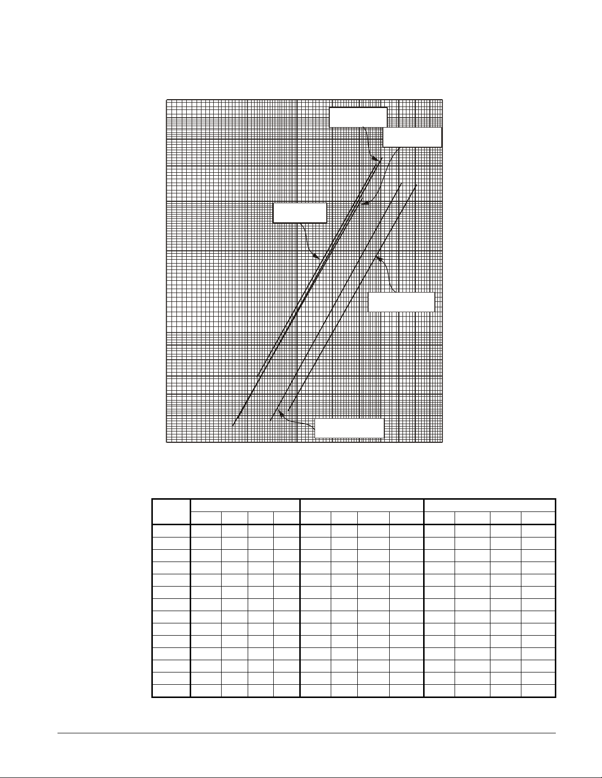
Figure 19, Evaporator Pressure Drops
200
300
400
500
600
700
800
900
1000
Flow Rate (GPM)
P
r
e
s
s
u
r
e
D
r
o
p
(
f
t
o
f
w
a
t
e
r
)
Flow Rate (L/s)
P
r
e
s
s
u
r
e
D
r
o
p
(
k
P
a
)
AGS Models
AGS Models
120, 130, 140
125, 135, 160
AGS Models
6 13 19 25 32 38 44 50 57 63
70
60
50
40
30
20
10
AGS Models
145
9
8
7
AGS Models
190, 195, 210
210
180
150
120
90
60
30
27
24
21
6
5
165, 170, 175, 180
4
100
Minimum/Nominal/Maximum Flow Rates
AGS
MODEL
120
125
130
135
140
145
160
165
170
175
180
190
195
210
MINIMUM FLOW NOMINAL FLOW MAXIMUM FLOW
gpm l/s ft kpa gpm l/s ft kpa gpm l/s ft kpa
175 11.1 4.6 13.7 280 17.7 10.6 31.6 467 29.5 26.5 79.1
182 11.5 4.9 14.6 292 18.5 11.8 35.2 486 30.8 29.2 87.2
188 11.9 5.3 15.8 300 19.0 12.9 38.5 501 31.7 30.4 90.7
196 12.4 5.6 16.7 314 19.9 13.5 40.3 524 33.1 33.5 100.0
201 12.7 5.9 17.6 321 20.3 13.6 40.6 535 33.8 30.4 90.7
215 13.6 6.9 20.6 343 21.7 16.1 48.0 572 36.2 40.2 119.9
227 14.4 7.2 21.5 363 23.0 17.1 51.0 606 38.3 43.0 128.4
241 15.2 4.8 14.4 385 24.4 11.3 33.8 642 40.6 28.6 85.3
252 16.0 5.2 15.7 403 25.5 12.3 36.7 672 42.6 31.1 92.7
259 16.4 5.7 17.0 414 26.2 12.9 38.5 690 43.7 32.6 97.2
269 17.1 5.9 17.7 431 27.3 13.9 41.4 718 45.5 35.0 104.5
278 17.6 5.2 15.5 445 28.2 12.3 36.7 742 47.0 30.7 91.6
285 18.1 5.4 16.1 457 28.9 12.8 38.2 761 48.2 32.6 97.3
302 19.1 5.9 17.6 483 30.6 14.3 42.7 805 50.9 34.5 103.0
18
15
12
IMM AGS-2 25
Physical Data, Standard Efficiency
Table 16, Physical Data, AGS 120C – AGS 140C
DATA
BASIC DATA
Unit Cap. @ 44°F LWT, 95°F Ambient
Temperature kW, (tons)
Unit Operating Charge lbs (kg) 131 (59) 131 (59) 131 (59) 131 (59) 131 (59) 131 (59)
Cabinet Dimensions
L x W x H, in. (mm)
Unit Operating Weight, lbs. (kg) 9452 (4291) 9452 (4291) 9452 (4291)
Unit Shipping Weight, lbs (kg) 9020 (4095) 9020 (4095) 9020 (4095)
Economizer No No No
COMPRESSORS, SCREW, SEMI-HERMETIC
Nominal Capacity, tons (kW) 60 (211) 60 (211) 60 (211) 70 (246) 70 (246) 70 (246)
CONDENSERS, HIGH EFFICIENCY FIN AND TUBE TYPE WITH INTEGRAL SUBCOOLER
Pumpdown Capacity, lbs (kg) 358 (163) 358 (163) 358 (163) 358 (163) 358 (163) 358 (163)
CONDENSER FANS, DIRECT DRIVE PROPELLER TYPE
No. of Fans – 30 in. Fan Dia. 8 8 8
No. of Motors -- hp (kW) 8 2 (1.5) 8 2 (1.5) 8 2 (1.5)
Fan & Motor RPM, 60Hz 1140 1140 1140
60 Hz Fan Tip Speed, fpm (m/s) 8950 (4224) 8950 (4224) 8950 (4224)
60 Hz Total Unit Airflow, cfm (l/s) 86900 (41020) 86900 (41020) 86900 (41020)
EVAPORATOR, DIRECT EXPANSION SHELL AND TUBE
Shell Dia.-Tube Length
in.(mm) - in. (mm)
Evaporator R-134a Charge lbs (kg) 1.95 (0.9) 1.95 (0.9) 1.95 (0.9) 1.95 (0.9) 1.95 (0.9) 1.95 (0.9)
Water Volume, gallons (liters) 49 (185) 49 (185) 49 (185)
Max. Water Pressure, psi (kPa) 152 (1048) 152 (1048) 152 (1048)
Max. Refrigerant Press., psi (kPa) 352 (2427) 352 (2427) 352 (2427)
120C 130C 140C
Ckt 1 Ckt 2 Ckt 1 Ckt 2 Ckt 1 Ckt 2
116.7 (410) 125.2 (440) 133.7 (470)
187 x 89 x 101
4750 x 2261 x 2565
15.5 x 82.4
(394 x 2093)
AGS MODEL NUMBER
187 x 89 x 101
4750 x 2261 x 2565
15.5 x 82.4
(394 x 2093)
187 x 89 x 101
4750 x 2261 x 2565
15.5 x 82.4
(394 x 2093)
Table 17, Physical Data, AGS 160C – AGS 180C
AGS MODEL NUMBER
DATA 160C 170C 180C
Ckt. 1 Ckt. 2 Ckt. 1 Ckt. 2 Ckt. 1 Ckt. 2
BASIC DATA
Unit Cap. @ 44°F LWT, 95°F Ambient
Temperature kW, (tons)
Unit Operating Charge, lbs (kg) 131 (59) 131 (59) 159 (72) 159 (72) 171 (78) 171 (78)
Cabinet Dim., L x W x H, in. (mm)
Unit Operating Weight, lbs. (kg) 10209 (4635) 11277 (5120) 11277 (5120)
Unit Shipping Weight, lbs (kg) 9484 (4306) 10552 (4791) 10552 (4791)
Economizer No No Yes
COMPRESSORS, SCREW, SEMI-HERMETIC
Nominal Capacity, tons (kW) 70 (246) 85 (299) 85 (299) 85 (299) 95 (334) 95 (334)
CONDENSERS, HIGH EFFICIENCY FIN AND TUBE TYPE WITH INTEGRAL SUBCOOLER
Pumpdown Capacity, lbs (kg) 358 (163) 358 (163) 399 (181) 399 (181) 399 (181) 399 (181)
CONDENSER FANS, DIRECT DRIVE PROPELLER TYPE
No. of Fans; 30 in. Fan Dia., 8 10 10
No. of Motors – hp (kW) 8 2 (1.5) 10 2 (1.5) 10 2 (1.5)
Fan & Motor RPM, 60Hz 1140 1140 1140
60 Hz Fan Tip Speed, fpm 8950 (4224) 8950 (4224) 8950 (4224)
60 Hz Total Unit Airflow, cfm (l/s) 86900 (41020) 108630 (51280) 108630 (51280)
EVAPORATOR, DIRECT EXPANSION SHELL AND TUBE
Shell Dia.,Tube Length in.(mm)
Evaporator R-134a Charge lbs (kg) 2.53 (1.1) 2.53 (1.1) 3.16 (1.4) 3.16 (1.4) 3.16 (1.4) 3.16 (1.4)
Water Volume, gallons (liters) 83 (314) 106 (401) 106 (401)
Max. Water Pressure, psi (kPa) 152 (1048) 152 (1048) 152 (1048)
Max. Refrigerant Press., psi (kPa) 352 (2427) 352 (2427) 352 (2427)
151.4 (532) 168.1 (591) 179.6 (631)
187 x 89 x 101
4750 x 2261 x 2565
19.4 x 82.4
(493 x 2093)
225 x 89 x 101
5715 x 2261 x 2565
19.4 x 105.1
(493 x 2670)
225 x 89 x 101
5715 x 2261 x 2565
19.4 x 105.1
(493 x 2670)
26 IMM AGS-2
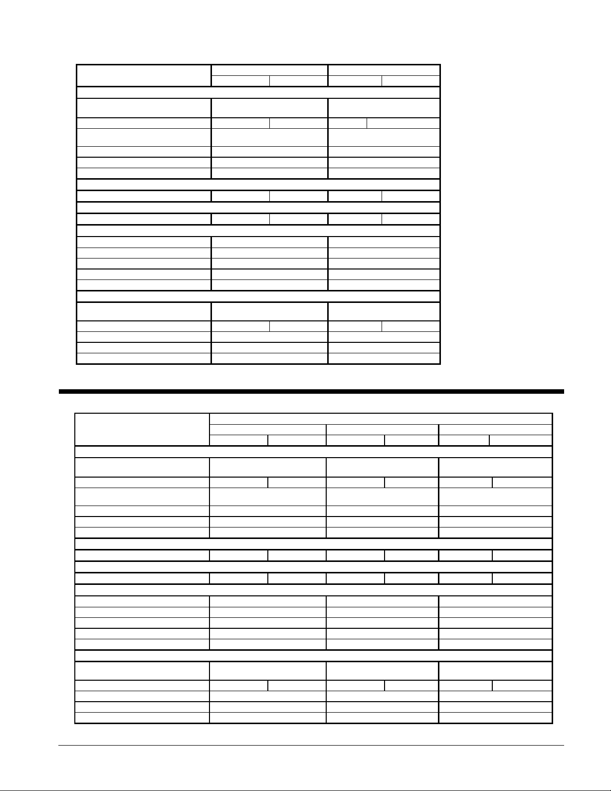
Table 18, Physical Data, AGS 190C – AGS 210C
DATA
BASIC DATA
Unit Cap. @ 44°F LWT, 95°F Ambient
Temperature kW, (tons)
Unit Operating Charge lbs (kg) 172 (78) 172 (78) 201 (91) 201 (91)
Cabinet Dimensions
L x W x H, in. (mm)
Unit Operating Weight, lbs. (kg) 11277 (5120) 11928 (5415)
Unit Shipping Weight, lbs (kg) 10552 (4791) 11011 (4999)
Economizer Yes Yes
COMPRESSORS, SCREW, SEMI-HERMETIC
Nominal Capacity, tons (kW) 95 (334) 95 (334) 95 (334) 95 (334)
CONDENSERS, HIGH EFFICIENCY FIN AND TUBE TYPE WITH INTEGRAL SUBCOOLER
Pumpdown Capacity, lbs (kg) 399 (181) 399 (181) 438 (199) 438 (199)
CONDENSER FANS, DIRECT DRIVE PROPELLER TYPE
No. of Fans -- 30 in. Fan Dia., 10 12
No. of Motors -- hp (kW) 10 2 (1.5) 12 2.5 (1.9)
Fan & Motor RPM, 60Hz 1140 1140
60 Hz Fan Tip Speed, fpm (m/s) 8950 (4224) 8950 (4224)
60 Hz Total Unit Airflow, cfm (l/s) 108630 (51280) 130360 (61530)
EVAPORATOR, DIRECT EXPANSION SHELL AND TUBE
Shell Dia.-Tube Length
in.(mm) - in. (mm)
Evaporator R-134a Charge lbs (kg) 3.63 (1.6) 3.63 (1.6) 3.63 (1.6) 3.63 (1.6)
Water Volume, gallons (liters) 106 (401) 104 (392)
Max. Water Pressure, psi (kPa) 152 (1048) 152 (1048)
Max. Refrigerant Press., psi (kPa) 352 (2427) 352 (2427)
AGS 190C AGS 210C
Ckt 1 Ckt 2 Ckt 1 Ckt 2
185.6 (653) 201.2 (707)
225 x 89 x 101
5715 x 2261 x 2565
19.4 x 105.1
(493 x 2670)
263 x 89 x 101
6680 x 2261 x 2565
19.4 x 105.1
(493 x 2670)
Physical Data, High Efficiency
Table 19, Physical Data, AGS 125C – AGS 145C
DATA
BASIC DATA
Unit Cap. @ 44°F LWT, 95°F Ambient
Temperature kW, (tons)
Unit Operating Charge lbs (kg) 159 (72) 159 (72) 159 (72) 159 (72) 159 (72) 159 (72)
Cabinet Dimensions
L x W x H, in. (mm)
Unit Operating Weight, lbs. (kg) 10930 (4962) 10930 (4962) 10485 (4760)
Unit Shipping Weight, lbs (kg) 10205 (4633) 10205 (4633) 9942 (4514)
Economizer No No No
COMPRESSORS, SCREW, SEMI-HERMETIC
Nominal Capacity, tons (kW) 60 (211) 60 (211) 60 (211) 70 (246) 70 (246) 70 (246)
CONDENSERS, HIGH EFFICIENCY FIN AND TUBE TYPE WITH INTEGRAL SUBCOOLER
Pumpdown Capacity, lbs (kg) 399 (181) 399 (181) 399 (181) 399 (181) 399 (181) 399 (181)
CONDENSER FANS, DIRECT DRIVE PROPELLER TYPE
No. of Fans – 30 in. Fan Dia., 10, 30 (762) 10, 30 (762) 10, 30 (762)
No. of Motors -- hp (kW) 10 2 (1.5) 10 2 (1.5) 10 2 (1.5)
Fan & Motor RPM, 60Hz 1140 1140 1140
60 Hz Fan Tip Speed, fpm (m/s) 8950 (4224) 8950 (4224) 8950 (4224)
60 Hz Total Unit Airflow, cfm (l/s) 108630 (51280) 108630 (51280) 108630 (51280)
EVAPORATOR, DIRECT EXPANSION SHELL AND TUBE
Shell Dia.-Tube Length
in.(mm) - in. (mm)
Evaporator R-134a Charge lbs (kg) 2.53 (1.1) 2.53 (1.1) 2.53 (1.1) 2.53 (1.1) 2.44 (1.1) 2.44 (1.1)
Water Volume, gallons (liters) 83 (314) 83 (314) 62 (236)
Max. Water Pressure, psi (kPa) 152 (1048) 152 (1048) 152 (1048)
Max. Refrigerant Press., psi (kPa) 352 (2427) 352 (2427) 352 (2427)
125C 135C 145C
Ckt 1 Ckt 2 Ckt 1 Ckt 2 Ckt 1 Ckt 2
121.6 (428) 130.9 (460) 143.0 (503)
225 x 89 x 101
5715 x 2261 x 2565
19.4 x 82.4
(493 x 2093)
AGS MODEL NUMBER
225 x 89 x 101
5715 x 2261 x 2565
19.4 x 82.4
(493 x 2093)
225 x 89 x 101
5715 x 2261 x 2565
19.4 x 105.1
(493 x 2670)
IMM AGS-2 27
 Loading...