

Page 1

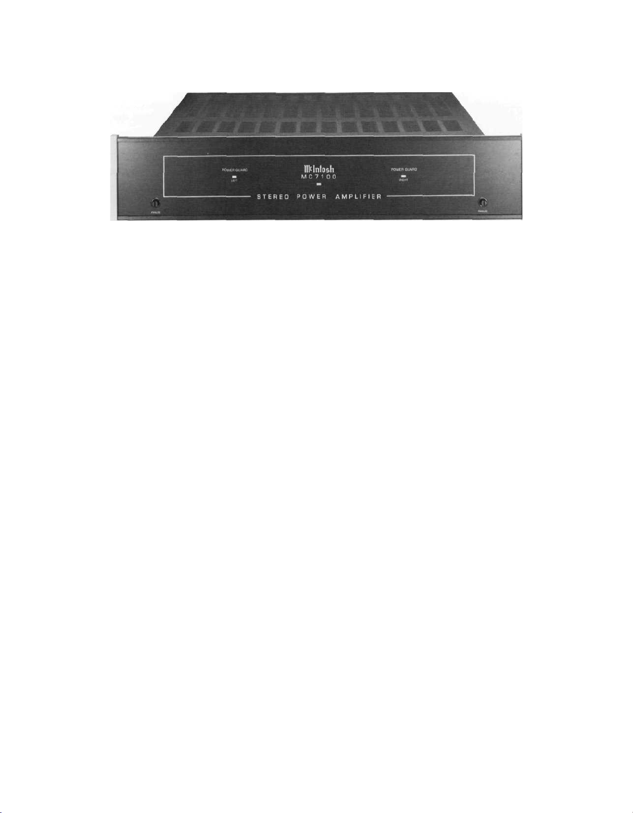
MC7100
POWER
AMPLIFIER
Page 2

Page 3
MC7100
POWER
AMPLIFIER
Page 4
IMPORTANT
SAFETY
INSTRUCTIONS
THESE
INSTRUCTIONS
ARE TO PROTECT
YOU AND THE
McINTOSH
INSTRUMENT.
BE SURE TO
FAMILIARIZE
YOURSELF
WITH THEM
1. Read all instructions - Read the safety and operating instructions before operating the instrument.
2. Retain Instructions - Retain the safety and operating instructions for future reference.
3. Heed warnings - Adhere to warnings and operating instructions.
4. Follow Instructions - Follow all operating and use instructions.
WARNING: TO REDUCE RISK OF FIRE OR ELECTRICAL SHOCK, DO NOT EXPOSE THIS IN-
STRUMENT TO RAIN OR MOISTURE.
5. Power Sources - Connect the power supply only to the type described in the operating instructions
or as marked on the unit.
6. Power-Cord Protection - Route power-supply cords so that they are not likely to be walked on or
pinched by items placed upon or against them, paying particular attention to cords at plugs,
convenience receptacles, and the point where they exit from the instrument.
7. Ventilation - Locate the instrument for proper ventilation. For example, the instrument should not
be placed on a bed, sofa, rug, or similar surface that may block ventilation openings; or, placed
in a built-in installation, such as a bookcase or cabinet, that may impede the flow of air through
the ventilation openings.
8. Heat - Locate the instrument away from heat sources such as radiators, heat registers, stoves, or
other appliance (including amplifiers) that produce heat.
9. Wall or Cabinet Mounting - Mount the instrument in a wall or cabinet only as described in the owner's
manual.
10. Water and Moisture - Do not use the instrument near water - for example, near a bathtub, washbowl,
kitchen sink, laundry tub, in a wet basement, or near a swimming pool, etc.
11. Cleaning-Clean the instrument by dusting with a dry cloth. Clean the panel with a cloth moistened
with a window cleaner.
12. Object and Liquid Entry - Do not permit objects to fall and liquids to spill into the instrument through
enclosure openings.
13. Nonuse Periods - Unplug the power cord from the AC power outlet when left unused for a long period
of time.
14. Damage Requiring Service - Service must be performed by qualified service personnel when:
A. The power supply cord or the plug has been damaged: or
B. Objects have fallen, or liquid has been spilled into the instrument; or
C. The instrument has been exposed to rain; or
D. The instrument does not appear to operate normally or exhibits a marked change in performance;
or
E. The instrument has been dropped, or the enclosure damaged.
15. Servicing - Do not attempt to service beyond that described in the operating instructions. All other
service should be referred to qualified service personnel.
16. Grounding or Polarization - Do not defeat the inherent design features of the polarized plug. Nonpolarized line cord adaptors will defeat the safety provided by the polarized AC plug.
17. CAUTION:
WITH AN EXTENSION CORD, RECEPTACLE OR OTHER OUTLET UNLESS THE BLADES CAN
BE FULLY INSERTED TO PREVENT BLADE EXPOSURE.
ATTENTION: POUR PREVENIR
FICHE POLARISEE AVEC UN PROLONGATEUR, UNE PRISE DE COURANT OU UNE AUTRE
SORTIE DE COURANT, SAUF SI LES LAMES PEUVENT ETRE INSEREES A FOND SANS EN
LAISSER AUCUNE PARTIE A DECOUVERT.
TO
PREVENT ELECTRICAL SHOCK
LES
CHOCS ELECTRIQUES
The lightning flash with arrowhead, within an equilateral triangle, is intended to alert the
user to the presence of uninsulated "dangerous voltage" within the product's enclosure
that may be of sufficient magnitude to constitute a risk of electric shock to persons.
DO NOT USE
THIS (POLARIZED) PLUG
PAS
UTILISER CETTE
Copyright 1992 © by
Mclntosh Laboratory Inc.
CAUTION:
REMOVE COVER (OR BACK). NO USER-SERVICABLE PARTS INSIDE.
REFER SERVICING TO QUALIFIED PERSONNEL.
The exclamation point within an equilateral triangle is intended to alert the user to the
presence of important operating and maintenance (servicing) instructions in the literature
accompanying the appliance.
TO
PREVENT THE RISK
OF
ELECTRIC SHOCK,
DO
NOT
WARNING: THIS UNIT IS CAPABLE OF PRODUCING HIGH SOUND
PRESSURE LEVELS. CONTINUED EXPOSURE TO HIGH SOUND
PRESSURE LEVELS CAN CAUSE PERMANENT HEARING IMPAIRMENT
OR LOSS. USER CAUTION IS ADVISED AND EAR PROTECTION IS
RECOMMENDED WHEN PLAYING AT HIGH VOLUMES.
2
Page 5

The serial number, purchase date, and Mclntosh Laboratory Service Contract number are
important to you for possible insurance claim or future service. Record this information here.
Serial Number Purchase Date
Service Contract Number
Upon application, Mclntosh Laboratory provides a Service Contract to the original purchaser.
Your Mclntosh Authorized Service Agency can expedite repairs when you provide the Service Contract with the instrument for repair.
SERVICE CONTRACT 4
INTRODUCTION 5
INSTALLATION 5, 6, 7
HOW TO CONNECT INPUTS 8
HOW TO CONNECT OUTPUTS 8, 9
CONNECTING DIAGRAMS 10
SPECIFICATIONS 11
PERFORMANCE CHARTS 12
TECHNICAL DESCRIPTION 13, 14
BLOCK DIAGRAM 15
TABLE OF
CONTENTS
3
Page 6

McINTOSH
THREE YEAR
SERVICE
CONTRACT
TAKE ADVANTAGE OF 3 YEARS OF CONTRACT SERVICE. . .
FILL IN THE APPLICATION NOW.
Your MC7100 Power Amplifier will give you many years of satisfactory performance. If you
have any questions, please contact,
Mclntosh Laboratory Inc.
2 Chambers Street
Binghamton, New York 13903-2699
Phone: 607-723-3512
An application for A THREE YEAR SERVICE CONTRACT is included with this manual.
The terms of the contract are:
1. If the instrument covered by this contract becomes defective, Mclntosh will provide all parts,
materials, and labor needed to return the measured performance of the instrument to the
original performance limits free of any charge. The service contract does not cover any
shipping costs to and from the authorized service agency or the factory.
2. Any Mclntosh authorized service agency will repair all Mclntosh instruments at normal
service rates. To receive the free service under the terms of the service contract, the service contract certificate must accompany the instrument when taken to the service agency.
3. Always have service done by a Mclntosh authorized service agency. If the instrument is
modified or damaged as a result of unauthorized repair the service contract will be cancelled. Damage by improper use or mishandling is not covered by the service contract.
4. The service contract is issued to you as the original purchaser. To protect you from
misrepresentation this contract cannot be transferred to a second owner.
5. Units in operation outside the United States and Canada are not covered by the Mclntosh
Factory Service Contract, irrespective of the place of purchase. Nor are units acquired
outside the USA and Canada, the purchasers of which should consult with their dealer
to ascertain what, if any, service contract or warranty may be available locally.
4
Page 7

The electrical and mechanical design of the MC7100 Power Amplifier is the result of the
many years of engineering and manufacturing experience of the design staff at Mclntosh.
This "Know How", along with the meticulous attention to design and production details, makes
the MC7100 one of the finest amplifiers ever produced by Mclntosh Laboratory.
The use of 4 complimentary connected output transistors per channel, allows not only full
power output into normal loads, but extra high current output to drive uneven speaker loads.
Some speakers have design characteristics that cause them to dip below their rated im-
pedances at certain frequencies. It is possible for the MC7100 to deliver as much as 18
amperes peak current into these lower impedance loads.
The MC7100 provides this extra current output with complete reliability due to the use of
Mclntosh Sentry Monitor protection circuits. Some power amplifier manufacturers have claimed
that their products do not use protection circuits since they compromise performance. The
real genius of Mclntosh engineering design has recognized these potential problems and completely eliminated them. Properly designed protection circuits assure you an amplifier that
will operate under all types of user conditions with maximum reliability and freedom from
possible speaker or amplifier damage. The benefits of these designs mean you own an amplifier
that will continue to operate safely for many years.
The MC7100 output is so distortion free, it is difficult to measure with conventional instruments. The performance limit is 0.005% maximum distortion, yet it is typical for an amplifier
to measure as low as 0.002% at mid frequencies into 8 ohms.
As in all Mclntosh power amplifiers, the famous patented Mclntosh POWER GUARD circuit is included. You never have to be concerned with possible amplifier overdrive. You will
not experience amplifier clipping with its harsh speaker damaging distortion when playing
wide dynamic range program sources such as compact discs.
Many other desirable features are included such as gold plated output terminals, DC output protection, thermal protection and a turn on delay circuit. A Toroidal wound power
transformer permits a low profile design with quiet cool operation.
Refer to the section in this manual titled TECHNICAL DESCRIPTION for detailed information on all the outstanding circuit and performance features of the MC7100.
INTRODUCTION
LOCATION
The MC7100 may be installed on a shelf or table, in a Mclntosh cabinet, or custom installed in furniture of your choice. Always provide adequate ventilation for the amplifier. The trouble free life of any electronic instrument is greatly extended by providing sufficient ventila-
tion. This prevents build-up of internal temperatures that can cause deterioration of circuit
components. The Mclntosh cabinet design allows for proper ventilation.
Allow enough clearance so cool air can enter at the bottom of the cabinet and be vented
from the top. Provide at least 1 1/2 inches (3.8cm) above the amplifier heat sink area so airflow
is not obstructed. The recommended minimum space for installation is 18 1/2 inches (47cm)
wide, 14 1/2 inches (36.8cm) deep, (including connectors) and 4 1/2 inches (11.5cm) high.
Allow 1 inch (2.54cm) in front of the mounting surface for panel clearance.
McINTOSH PANLOC MOUNTING SYSTEM
The PANLOC system of installing equipment is a product of Mclntosh research. Two steel
PANLOC mounting shelves are attached to the front panel at each side of the panel cutout,
using the screws and brackets provided. The amplifier has runners on the bottom of its chassis,
INSTALLATION
5
Page 8

INSTALLATION
allowing it to slide into the shelves. When the unit has been positioned completely into the
cabinet and its front panel is against the cabinet panel, it can be locked into position. Turn
each PANLOC button approximately one-quarter turn clockwise to lock. Turn the PANLOC button
one-quarter turn counterclockwise to unlock the unit so it can be removed from the cabinet.
UNPACKING
Open the carton and remove the PANLOC shelves, the hardware package and the mounting template. Lift the amplifier up off the shipping pallet and remove the plastic bag. The
amplifier is now ready for shelf or table top installation.
If the amplifier is to be installed in a Mclntosh cabinet or custom installation, place it carefully
upside-down on a flat surface and unscrew the four plastic feet from the bottom of the amplifier
chassis.
INSTALLING IN A McINTOSH CABINET
Guide the amplifier AC power cord through the front panel opening to the back of the cabinet.
Slide the amplifier into the opening, making sure the rails on the bottom of each side of the
amplifier chassis engage the tracks on the PANLOC shelves. Slide the amplifier completely
into the cabinet until the back side of its front panel is pressing gently against the front of
the cabinet panel. Turn the PANLOC buttons approximately one-quarter turn clockwise to lock
the amplifier into the cabinet. Turn the buttons one-quarter turn counterclockwise to unlock
and remove the amplifier.
CUSTOM INSTALLATION
1. MARK THE CABINET FRONT PANEL
Tape the plastic mounting template to the cabinet panel in the position where the amplifier
is to be mounted. The broken lines that represent the outline of the rectangular cutout also
represent the outside dimensions of the amplifier chassis. Make sure these lines clear any
shelves, partitions or any other equipment mounted in the same cabinet. With the template
in place, first mark the six A and B holes, and the four small holes that locate the corners
of the cutout. Then join the four corner markings with a ruler or straightedge.
2. DRILL THE HOLES
Use a drill with a 3/16 inch (5mm) bit. Drill perpendicular to the front panel the six A and
B holes. Then, using a drill bit slightly larger than the tip of your saw blade, drill one hole at
each of two diagonally opposite corners. The holes should barely touch the inside edge of the
penciled outline. Before taking the next step, be sure the six A and B holes have been drilled.
6
Page 9

3. SAW THE PANEL CUTOUT
First make the two long horizontal cuts. Then make the two short vertical cuts. After the
cutout is finished, use a file to square the corners and smooth any rough edges.
4. INSTALL THE PANLOC MOUNTING STRIPS
The hardware package includes two
mounting strips and two black flat head
6/32 x 1 1/4 inch (31.8mm) screws and two
6/32 x 1 1/4 inch (31.8mm) fillister head
screws. Place a mounting strip behind
each edge of the cutout and secure it to
the back side of the panel inserting a black
flat head 6/32 screw through the center
holes marked B on the template. Make
sure the screws are drawn flush or slightly into the wood before attaching the PANLOC shelves.
5. ATTACH THE PANLOC SHELVES
Position the PANLOC shelves inside the
cutout with the short flange against the
front face of the cabinet panel. Fasten the
shelves by inserting two fillister head 6/32
screws through the holes in each of the
PANLOC shelf flanges, through the front
panel and into the threaded receptacle on
the mounting strips.
INSTALLATION
6. INSTALL THE AMPLIFIER
Guide the amplifier AC power cord through the panel opening to the back of the cabinet.
Slide the amplifier into the opening, making sure the rails on the bottom of each side of the
amplifier chassis engage the tracks on the PANLOC shelves. Slide the amplifier completely
into the cabinet until the back side of its front panel is pressing gently against the front of
the cabinet panel. Turn the PANLOC buttons approximately one-quarter turn clockwise to lock
the amplifier in the cabinet. Turn the PANLOC buttons one-quarter turn counterclockwise to
unlock and remove the amplifier.
7
Page 10

HOW
TO
CONNECT
INPUTS
INPUT CABLES
Use shielded cables to connect the signals from the preamplifier or other signal source
to the power amplifier. To minimize the possibility of hum pickup or interference, locate the
cables away from AC power cords or loudspeaker cables.
Use good quality cables. Your Mclntosh dealer can advise you on the types and lengths
of cables that will work best in your installation.
STEREO OPERATION
Use shielded single conductor cable with RCA type connectors. Connect a cable from the
LEFT channel of a preamplifier output to the L (left) INPUT jack on the MC7100. Connect
the RIGHT channel preamplifier output to the R (right) INPUT jack on the MC7100.
MONOPHONIC (BRIDGED) OPERATION
A rear panel MODE switch allows the MC7100 to be used as a normal stereo amplifier,
or as a bridged mono amplifier.
Connect a shielded cable from a mono signal source to the R (right) /MONO input jack
on the MC7100. Set the mode switch to MONO. Only the right channel LEVEL control functions in MONO operation. The outputs must be connected as indicated in HOW TO CONNECT
OUTPUTS for proper mono operation.
INPUT LEVEL CONTROLS
These controls adjust the input volume levels of each channel. When the LEVEL controls
are in the 12 o'clock or DETENT position, the amplifier input sensitivity for the rated 100 watts
output is 2.5 volts.
HOW
TO
CONNECT
OUTPUTS
THE 2.5 VOLT SENSITIVITY SETTING IS RECOMMENDED FOR BEST OPERATION WITH A
McINTOSH PREAMPLIFIER.
Turning the LEVEL controls fully on, (clockwise), will give a higher amplifier sensitivity of
1.4 volts which may be required for other applications.
SPEAKER CABLES
Use high quality speaker cables since this is an important link in your stereo system. Selec-
tion of the proper size and type of speaker cable is necessary for you to receive the best
possible performance from your amplifier and speaker combination. Consult your Mclntosh
dealer for recommendations on the cables that will best fit the needs of your stereo installation.
STEREO OPERATION
(SET THE MODE SWITCH SET TO STEREO POSITION)
The outputs of the MC7100 are direct coupled, and match speaker loads from four
to eight ohms and higher.
Connect a cable from the LEFT speaker COMMON terminal to the amplifier L (Left) - (minus)
OUTPUT terminal. Connect a cable from the LEFT speaker HOT terminal to the amplifier L
(Left) + (Plus) OUTPUT terminal. Connect the right speaker to the right channel output terminals in a similar manner.
The COMMON and HOT terminals, (- and +), of both speakers must be connected in an
identical manner to the proper amplifier output terminals so they will operate IN PHASE. This
means that the speaker driver surfaces move back and forth the same in each speaker
8
Page 11

system. Almost all loudspeaker systems have their hot and common terminals color coded,
with red usually as hot or plus. The output signals of all Mclntosh power amplifiers are always
IN PHASE with the input signals.
The crosstalk between channels on the MC7100 is almost none existent, so each channel
can be used as a separate monophonic amplifier. An example would be one channel feeding
background music to a given area, and the other channel feeding a different program signal
to another area.
MONOPHONIC (BRIDGED) OPERATION
(SET THE MODE SWITCH TO MONO POSITION)
Connect a cable from the monophonic speaker COMMON terminal to the MONO - (Minus)
amplifier output terminal. Connect a cable from the speaker HOT terminal to the amplifier
MONO + (Plus) terminal.
The MC7100 amplifier monophonic output signal will be in phase with the input signal when
the speaker is connected as indicated.
It is recommended that speaker loads no lower than 8 ohms be used with the
amplifier in the bridged Monophonic configuration.
HOW TO CONNECT AC POWER
The MC7100 is designed to operate on 120 volts 50/60Hz current. Plug the power cord
into a switched AC receptacle on the back of a preamplifier or other accessory component.
The plug blades are polarized; so be certain the plug is fully inserted in the outlet to prevent
blade exposure. (The MC7100 has no AC power switch, so it must be switched on and off
by a preamplifier or other accessory component.) Make certain that the AC outlet used can
supply at least 6 amperes of current. The amplifier can draw up to 5 amperes from the AC
power line when both channels are producing rated power output.
The auxiliary AC outlet on the amplifier rear panel will provide up to 600 watts (5 amperes)
current, and is not fused or switched.
HOW
TO
CONNECT
OUTPUTS
CAUTION: TO PREVENT ELECTRIC SHOCK, DO NOT CONNECT THE POLARIZED AC
PLUG ON THIS UNIT TO AN EXTENSION CORD OR OTHER AC OUTLET THAT IS NOT
DESIGNED TO ACCEPT POLARIZED PLUGS. THE PLUG MUST BE FULL Y INSERTED
TO PREVENT BLADE EXPOSURE AND MAINTAIN LINE POLARITY.
FUSE
A 5 ampere fuse protects the MC7100 circuits. This fuse does not protect the auxiliary
AC outlet.
FRONT PANEL
The front panel is the "Classic Mclntosh" black glass with back lighted nomenclature.
The RED AC power indicator as well as the teal colored panel nomenclature will illuminate
when AC power is on. The amber POWER GUARD indicators will flash whenever the POWER
GUARD circuit is activated.
9
Page 12

STEREO
CONNECTION
BRIDGED
MONOPHONIC
CONNECTION
LEFT
SPEAKER
4 OR 8
OHMS
RIGHT
SPEAKER
4 OR 8
OHMS
STEREO
MUST BE IN
STEREO POSITION
FOR STEREO PROGRAMS
PREAMPLIFIER
MONO
10
8 OHM
SPEAKER
STEREO
MUST BE IN
MONO POSITION
FOR MONO PROGRAMS
MONO
MONO
INPUT
SIGNAL
Page 13

PERFORMANCE LIMITS
Performance limits are the maximum
deviation from perfection permitted for a
Mclntosh instrument. We promise you that
when you purchase a new MC7100 from a
Mclntosh Franchised Dealer, it will be
capable of performance at or better than
these limits.
A-WEIGHTED SIGNAL-TO-NOISE RATIO
95dB (115dB below rated output)
INTERMODULATION DISTORTION. SMPTE
0.005% maximum if instantaneous peak
power output does not exceed twice the output power rating.
RATINGS
SPECIFICATIONS
STEREO POWER OUTPUT
150 watts into 4 ohm loads or 100 watts
into 8 ohm loads minimum sine wave continuous average power output per channel,
both channels operating.
The output RMS voltage is:
28.3V across 8 ohms
24.5V across 4 ohms
MONOPHONIC (BRIDGED)
300 watts into an 8 ohm load minimum
sine wave continuous average power output.
The output RMS voltage is: 49 volts across
8 ohms.
OUTPUT LOAD IMPEDANCE
STEREO
8 or 4 ohms
MONOPHONIC
8 ohms
RATED POWER BAND
20Hz to 20,000Hz
TOTAL HARMONIC DISTORTION
0.005% maximum harmonic distortion at
any power level from 250 milliwatts to rated
power output.
IHF DYNAMIC HEADROOM
8 ohms, 1.7dB
4 ohms, 2.1dB
FREQUENCY RESPONSE
+ 0, -0.25dB from 20Hz to 20.000Hz
+ 0, -3.0dB from 10Hz to 100,000Hz
WIDE BAND DAMPING FACTOR
8 ohms, 200
4 ohms, 100
INPUT IMPEDANCE
20,000 ohms
POWER GUARD
Clipping is prevented and THD does not
exceed 2% with up to 14dB overdrive at
1000Hz.
POWER REQUIREMENTS
120 volts, 50/60HZ, 3.0 amps UL/CSA
MECHANICAL
SIZE
Front panel: 17 1/2 inches (44.5cm) wide,
by 3 5/8 inches (9.2cm) high.
Chassis: 14 3/4 inches (37.5cm) wide, by
2 3/8 inches (6cm) high, by 14 1/2 inches
(36.9cm) deep, (from back of front panel), including connectors. Panel clearance re-
quired in front of the mounting surface is 1
inch (2.54cm).
FINISH
Glass with special gold/teal nomenclature
illumination. Chassis and chassis cover are
black.
WEIGHT
24 pounds (11 Kg) net; 35 pounds (15.9Kg)
in shipping carton.
INPUT SENSITIVITY
1.4 volts (2.5 volts at gain control center
detent)
11
Page 14

PERFORMANCE
CHARTS
12
Page 15

DESIGN PHILOSOPHY
The MC7100 stereo power amplifier is designed to operate loudspeakers with a nominal
impedance of 4 to 8 ohms. It features a new circuit design that keeps distortion levels so
low it takes special test gear for accurate measurements.
The design philosophy that resulted in the outstanding performance of this amplifier in-
volved several different techniques. Every stage of voltage or current amplification was designed to be as linear as possible prior to the use of negative feedback,
1. Each transistor is selected to have nearly constant current gain (Beta) over its entire
operating range.
2. The load impedance presented to each amplification stage is made as uniform as possible for all signal levels.
3. The input impedance of each amplifier stage is increased and made more linear by using emitter degeneration whenever possible.
4. Resistors and capacitors in the signal path are carefully selected to have exceedingly
low voltage coefficients (change of resistance or reaction with applied voltage). Precision
metal film resistors and low dielectric absorption film capacitors are used in all critical circuit locations.
5. Output transistors have matched uniform current gain, high current gain-bandwidth product, low output capacitance and large active-region safe operating area. These characteristics
together with the automatic tracking bias system eliminate crossover distortion.
TECHNICAL
DESCRIPTION
PROTECTION CIRCUITS
Some manufacturers of power amplifiers claim that their products do not need or use pro-
tection circuits and that such circuits compromise performance. Mclntosh feels that protection circuits are desirable and necessary to prevent amplifier or loudspeaker damage due
to abnormal circumstances. The genius of Mclntosh engineering has resulted in protection
circuits which have no effect or compromise on the normal performance of a power amplifier.
The SENTRY MONITOR circuit is a good example. The MC7100 incorporates seven specific
protection circuits to enhance its performance, increase its reliability and protect loudspeakers.
SENTRY MONITOR CIRCUIT
All power transistors have limits for the maximum amount of power they can handle. The
MC7100 output transistors and power supply have been designed to allow very high current
flow into properly matched load impedances. However, if a short circuit or very low load im-
pedance is connected to the MC7100 outputs, destructive current levels could be reached
if it was not controlled by the SENTRY MONITOR circuit. This circuit senses the dynamic
operating time, voltage and current of the output stage, and controls it to safe operating limits.
The SENTRY MONITOR circuit does not limit the power output available from the amplifier.
THERMAL CONTROL
All power transistors have limits to the maximum amount of heat they can safely tolerate.
The MC7100 uses a highly efficient amplifying circuit which produces relatively little heat
for the output power produced. The amplifier uses large area heat sinks to efficiently dissipate
what heat it does generate. Natural convection air flow is sufficient for safe cool operation.
If the cooling air is blocked, or the amplifier operating temperature is forced too high, ther-
mal cutout switches will turn off the speakers. Both POWER GUARD indicators will light con-
tinuously to show that thermal protection is operating. When the problem is corrected and
13
Page 16

TECHNICAL
DESCRIPTION
the amplifier cools down to its normal operating temperature, the speakers will be turned
back on.
DIRECT CURRENT FAILURE PROTECTION
A protection circuit is provided that turns off the speakers if for any reason a DC voltage
should appear at the output terminals. This prevents possible speaker damage.
POWER GUARD
A unique and patented feature of Mclntosh power amplifiers insures that each channel
of the MC7100 will deliver full power, free of clipping distortion. Clipping occurs when an
amplifier is overdriven past its output design capabilities. An overdriven amplifier can produce both audible and ultrasonic distortion levels approaching 40%. The audible distortion
is certainly unpleasant, but the ultrasonic distortion is also undesirable, since it can damage
tweeter loudspeakers.
The POWER GUARD circuit acts as a waveform comparator, monitoring both the input
and output waveforms. Under normal operating conditions there are no differences between
these waveforms. When an amplifier is overdriven beyond its maximum distortion free output, then there will be a difference between the two waveforms. If the difference exceeds
0.3% (equivalent to 0.3% harmonic distortion), the amber POWER GUARD indicator will light.
If the difference continues to increase, the POWER GUARD circuit controls an electronic
attenuator at the input to reduce the gain of the amplifier just enough to prevent any further
increase in distortion. Distortion will not exceed 2% with as much as 14dB overdrive.
A Mclntosh power amplifier with POWER GUARD will always deliver its maximum distortion free output. This power is always well above the rated power due to the Mclntosh
philosophy of conservative design. You will never experience the harsh and damaging distortion due to clipping when using a Mclntosh POWER GUARD amplifier.
14
Page 17

BLOCK DIAGRAM
15
Page 18

039942
Page 19

Page 20

 Loading...