

Page 1
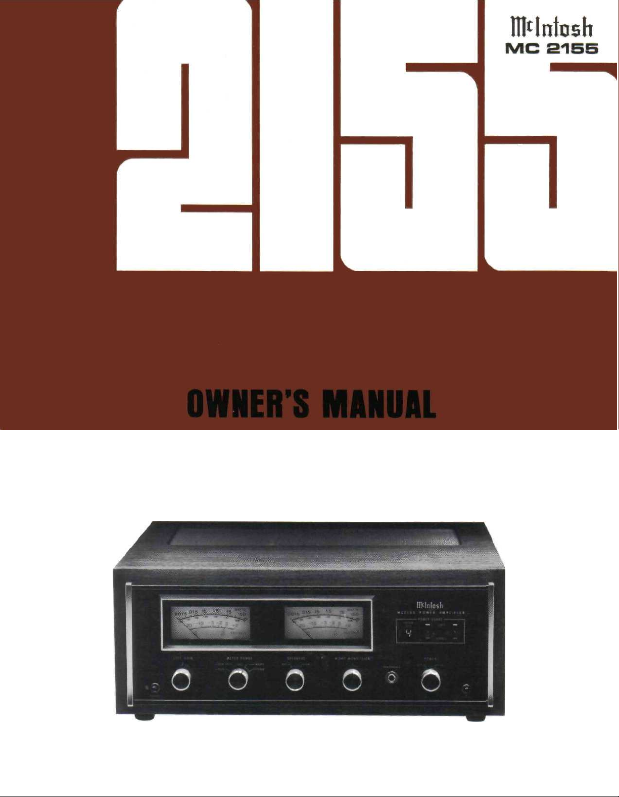
THE MclNTOSH MC 2155 SOLID STATE STEREO
POWER AMPLIFIER
Reading Time: 31 Minutes
Price $2.00
Page 2

VARIOUS REGULATORY AGENCIES REQUIRE THAT WE BRING THE FOLLOWING
INFORMATION TO YOUR ATTENTION. PLEASE READ IT CAREFULLY.
WARNING: TO PREVENT FIRE OR SHOCK
HAZARD, DO NOT EXPOSE THIS UNIT TO
RAIN OR MOISTURE.
The Mclntosh you have purchased is a Model
MC 2155. It has a serial number located on the rear panel
of the chassis. Record that serial number here:
Serial Number
The model, serial number and purchase date are im-
portant to you for any future service. Record the purchase date here:
Purchase date
Upon application, Mclntosh Laboratory provides a
Three-Year Service Contract. Your Mclntosh authorized
Service Agency can expedite repairs when you provide
the Service Contract with the instrument for repair. To
assist, record your Service Contract number here:
Service Contract Number
Page 3
Your MC 2155 Stereo Power Amplifier
will give you many years of pleasant
and satisfactory performance. If you
have any questions, please contact:
CUSTOMER SERVICE
Mclntosh Laboratory Inc.
2 Chambers Street
Binghamton, New York 13903-9990
Phone: 607-723-3512
Take Advantage of 3 years
of Contract Service...
Fill in the Application NOW.
Contents
SERVICE 1
INSTALLATION 2
HOW TO CONNECT 4
FRONT PANEL INFORMATION 9
REAR PANEL INFORMATION 11
PERFORMANCE LIMITS AND RATINGS 12
PERFORMANCE CHARTS 13
TECHNICAL DESCRIPTION 15
BLOCK DIAGRAM 17
MclNTOSH THREE YEAR SERVICE CONTRACT
An application for A THREE YEAR SERVICE CONTRACT is included with this manual.
The terms of the contract are:
1. Mclntosh will provide all parts, materials
and labor needed to return the measured
performance of the instrument to the
original performance limits. The SERVICE CONTRACT does not cover any
shipping costs to and from the authorized service agency or the factory.
2. Any Mclntosh authorized service agency
will repair Mclntosh instruments at nor-
mal service rates. To receive service
under the terms of the SERVICE CONTRACT, the SERVICE CONTRACT CERTIFICATE must be presented when the
instrument is taken to the service agency.
3. Always have service done by a
Mclntosh authorized service agency. If
the instrument is modified or damaged
as a result of unauthorized repair, the
SERVICE CONTRACT will be cancelled.
Damage by improper use or mishan-
dling is not covered by the SERVICE
CONTRACT.
4. The SERVICE CONTRACT is issued to
you as the original purchaser. To protect you from misrepresentation, this
contract cannot be transferred to a second owner.
5. To receive the SERVICE CONTRACT,
your purchase must be made from a
Mclntosh franchised dealer.
6. Your completely filled in application for
the SERVICE CONTRACT must be post-
marked within 30 days of the date of
purchase of the instrument.
7. To receive the SERVICE CONTRACT, all
information on the application must be
filled in. The SERVICE CONTRACT will
be issued when the completely filled in
application is received by Mclntosh
Laboratory Incorporated in Binghamton,
New York.
8. Units in operation outside the United
States and Canada are not covered by
the Mclntosh Factory Service Contract,
irrespective of the place of purchase.
Nor are units acquired outside the
U.S.A. and Canada, the purchasers of
which should consult with their dealer
to ascertain what, if any, service contract or warranty may be available locally.
Copyright 1981 © by Mclntosh Laboratory Inc. 1
Page 4
tion the instrument can be mounted in any position.
The recommended minimum space for installation
is 15 inches (38.1 cm)deep, 17 inches (43.2 cm) wide,
and 6 inches (15.2 cm) high.
To install the instrument in a Mclntosh cabinet,
follow the instructions that are enclosed with the
cabinet for any other type of installation, follow
these instructions:
1. Open the carton and remove the PANLOC brackets, hardware package and mounting template. Remove the MC 2155 from the plastic bag and place it
upside down on the shipping pallet then unscrew
the four plastic feet from the bottom of the chassis.
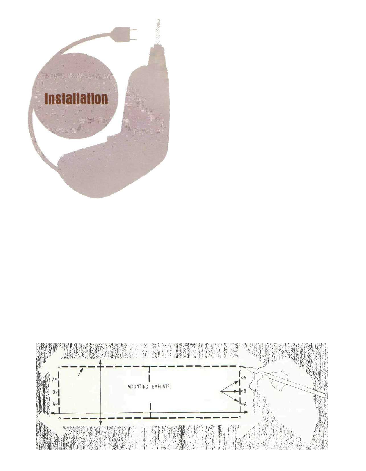
2. Mark the cabinet panel
Place the mounting template in the position on the
cabinet pane! where the instrument is to be install-
ed, and tape it in place. The broken lines that represent the outline of the rectangular cutout also repressent the outside dimensions of the chassis. Make
sure these lines clear shelves, partitions or any
equipment. With the template in place, first mark the
six A and B holes and the four small holes that
locate the corners of the cutout. Then, join the four
corner markings with pencil lines using the edge of
the template as a straight edge.
The PANLOC system of installing equipment conveniently and securely is a direct result of Mclntosh
research. By depressing the two PANLOC buttons
on the front panel, the instrument either can be locked firmly in place or it can be unlocked so that the
chassis can slide forward, giving you easy access to
the top and rear panels.
The trouble-free life of an electronic instrument is
greatly extended by providing sufficient ventilation
to prevent the build-up of high internal temperatures
that cause deterioration. Allow enough clearance so
that cool air can enter at the bottom of the cabinet
and be vented from the top. With adequate ventila-
3. Drill Holes
Use a drill with a 3/16 inch bit held perpendicular to the
panel and drill the six A and B holes. Then, using a drill
bit slightly wider than the tip of your saw blade, drill
one hole at each of two diagonally opposite corners.
The holes should barely touch the inside edge of the
penciled outline. Before taking the next step, make
sure that the six A and 8 holes have been drilled.
4. Saw the Panel Cutout
Saw carefully on the inside of the penciled lines.
First make the two long cuts and then the two short
cuts. After the rectangular opening has been cut out.
use a file to square the corners and smooth any
irregularities in the cut edges.
2
Page 5
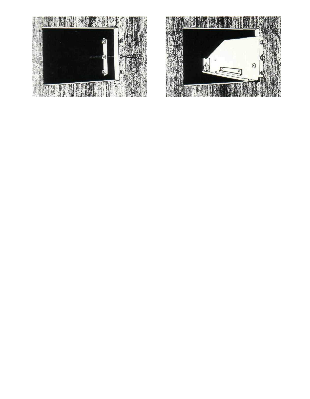
5 Install the Mounting Strips
In the hardware package you will find two mounting
strips and two sets of machine screws. For panels
that are less than ½ inch thick, use the ¾ inch
screws: for panels that are more than ½ inch thick,
use the 1 ¼ inch screws.
Starting at the right-hand side of the panel, insert
a screw of proper length into the center hole in the
panel. marked B on the template. On the back of the
panel, align a mounting strip with the holes in the
panel and tighten the screw until the screwhead is
pulled slightly into the wood.
Repeat this procedure to attach the mounting
strip to the left side of the panel.
6. Attach the PANLOC Brackets
Using two screws of proper length in the A holes on
each side, attach the PANLOC brackets to the cabinet panel; the short flange is mounted against the
front (face) of the cabinet panel. The screws pass
through the PANLOC bracket flange, the cabinet
panel, and then through the mounting strips
previously mounted.
7. Install the Instrument
Guide the AC power cord through the panel opening
to the back of the cabinet; then, slide the instrument
into the opening carefully so that the rails on the
bottom of each side of the chassis engage the
tracks on the mounting brackets. Continue to slide
the instrument into the cabinet until it is stopped by
the adjust position latches. Press the latches inward, this permits the instrument to slide into the
cabinet until its front panel is flush with the cabinet
panel. Depress the PANLOC buttons at the lower left
and right corners of the instrument panel to lock the
unit firmly in the cabinet. Depressing the PANLOC
buttons again will unlock the instrument so that it
can slide forward to the adjust position; if you press
inward on the adjust position latches then you can
remove the instrument from the cabinet.
3
Page 6

How to Connect
INPUT
STEREO OPERATION
Use shielded cables to connect the signal from
the preamplifier or signal source to the power
amplifier. To minimize the possibilty of hum the
shielded cables should be run parallel to each other
or loosely twisted together. Locate the cables away
from speaker leads and AC power cords. All connections are made on the back panel of the MC 2155.
For stereo operation, the left output of the
preamplifier should be plugged into the Left input
jack of the power amplifier. The right output of the
preamplifier should be plugged into the Right
(Mono) input jack of the power amplifier.
In stereo operation the MODE SWITCH must be in
the STEREO position.
MONOPHONIC OR SINGLE CHANNEL OPERATION
A shielded cable from the signal source is plug-
ged into the Right (Mono) input jack of the MC 2155
only. The MODE SWITCH on the back panel of the
amplifier must be placed in one of the MONO positions. In the MONO positions the output of the right
channel input amplifier is fed to both left and right
power amplifiers. The Left INPUT is disconnected.
Only the signal fed into the Right (MONO) input will
be amplified.
Be certain that the MC 2155 is never operated in
the stereo mode with the outputs connected for
monophonic operation. Should the MODE SWITCH
be left in the STEREO position and the outputs remain strapped for a mono parallel load, one channel
will attempt to drive the other which causes high circulating currents and overheating.
duction for which the loudspeakers have been de-
signed. If undersize wire is used, resistance is added
to the amplifier/loudspeaker combination which
adversely affects the performance. Added resistance causes depreciation of damping characteristics, modification of frequency response and reduction in power output.
Use lamp cord or wire with similar insulation to
connect the speakers to the amplifier. In all cases,
the leads to and from the speaker should be twin
conductor or twisted together. When using 8 ohm
speakers and for the normally short distances of
under 30 feet between the amplifier and speaker, #
18 wire or larger can be used. For distances over 30
feet use larger diameter wire. Select the correct size
wire from the chart below. It is recommended that
the DC resistance of the speaker leads be less than
5% of the speaker impedance. Resistance of the
leads should be computed for the length of wire both
to and from the speaker or speakers.
For multiple speaker operation, run separate
leads from the amplifier to the speakers.
MAXIMUM WIRE LENGTHS
Wire
Gauge
18
16
14
12
10
For 4 Ohm Load
Feet
15
25
40
60
100
Meters
4.57
7.62
12.19
18.29
30.48
For 8 Ohm Load
Feet
30
50
80
120
200
Meters
9.14
15.24
24.38
36.58
60.96
Wire lengths above represent the wire resistance
equal to 5% of the speaker impedance.
OUTPUT
Be certain the loudspeakers connected to the MC
2155 are capable of handling the power output of the
amplifier.
Selection of the proper gauge wire to connect the
loudspeakers preserves the quality of sound repro-
STEREO OPERATION
Check the impedance of the speaker which is
usually identified on the speaker itself or in the
owner's manual. Connect a lead from the common
terminal of the left speaker to the amplifier LEFT
OUTPUT terminal strip COMmon screw. Connect
4
Page 7

another lead from the other terminal of the
loudspeaker to the left output terminal marked for
the impedance of the speaker on the LEFT OUTPUT
terminal strip. The right channel speaker is connected in the same manner to the RIGHT OUTPUT
terminal strip.
When multiple speakers are to be connected to
either or both outputs, the combined load im-
pedance must be calculated. The load must be con-
nected to the appropriate impedance tap. Use this
table to aid in selecting the correct impedance
match:
Load
impedance
in ohms
0.8 to 1.6
1.6 to 3.2
3.2 to 6.4
6.4 and up
Connect for:
1 ohm output
2 ohm output
4 ohm output
8 ohm output
For monophonic operation using the MONO
PARALLEL mode, output impedances of ½, 1,2, and
4 ohms are accomodated. Connect as listed below.
The common output terminal is at ground potential.
Load Impedance
In Ohms
½
1
2
4
Connect - Speaker
Lead To:
Either Left or Right
Common Terminal
Either Left or Right
Common Terminal
Either Left or Right
Common Terminal
Either Left or Right
Common Terminal
Connect + Speaker
Lead To:
Both Left and Right
1 Ohm Terminals
Both Left and Right
2 Ohm Terminals
Both Left and Right
4 Ohm Terminals
Both Left and Right
8 Ohm Terminals
FOR MONOPHONIC CONSTANT VOLTAGE LINE
OPERATION
For output
voltage of
Connected for:
If a load impedance is used that is lower than the
output impedance tap, then reduced power and possible distortion will result. If a load impedance is used that is higher than the output impedance tap,
then neither the signal nor the amplifier will be
harmed but the power available is reduced.
FOR STEREO CONSTANT VOLTAGE OPERATION:
For output
voltage of
25 volts
Connect for:
4 ohms
MONOPHONIC OR SINGLE CHANNEL OPERATION
When the MC 2155 is used as a monophonic or
single channel power amplifier the two channels are
combined to produce output up to 300 watts. The
outputs must be connected as described below.
For monophonic operation using the MONO
BRIDGE mode, output impedances of 2, 4, 8, and 16
ohms are accomodated. Output connections are
made by connecting to the output terminals as
fisted below. Note that neither output terminal is at
ground potential.
25 volts
2 ohm output (mono)
Be certain that the MC 2155 is never operated in
the stereo mode with the outputs connected for
monophonic operation. Should the MODE SWITCH
be left in the STEREO position and the outputs remain strapped for a mono parallel load, one channel
will attempt to drive the other which causes high circulating currents and overheating.
AC POWER
The MC 2155 operates on 120 volts 50/60 Hz. The
auxiliary AC OUTLET on the MC 2155 is not fused or
switched.
Load Impedance
In Ohms
2
4
8
16
Connect - Speaker
Lead To:
Left 1 Ohm Terminal
Left 2 Ohm Terminal
Left 4 Ohm Terminal
Left 8 Ohm Terminal
Connect + Speaker
Lead To:
Right 1 Ohm Terminal
Right 2 Ohm Terminal
Right 4 Ohm Terminal
Right 8 Ohm Terminal
5
Page 8

Stereophonic
Connections
PROGRAM SOURCE
—
+
LEFT
SPEAKER
—
+
MUST BE IN STEREO
POSITION FOR
STEREO PROGRAMS
RIGHT
SPEAKER
6
Page 9

Mono-Bridge
Connections
PROGRAM SOURCE
(CONNECTIONS FOR
8 OHM SPEAKER
ILLUSTRATED)
— +
CONNECTIONS SHOWN FOR MONO
WHEN MODE SWITCH
IS IN THE MONO-BRIDGE POSITION
SPEAKER
7
Page 10

Mono-Parallel
Connections
PROGRAM SOURCE
(CONNECTIONS FOR
4 OHM SPEAKER
ILLUSTRATED)
—
+
CONNECTIONS SHOWN FOR MONO
WHEN MODE SWITCH
IS IN THE MONO-PARALLEL POSITION
SPEAKER
8
Page 11

The Front Panel Controls and
How to Use Them
METERS
Output power monitor meters indicate the output
power of each channel. Each meter has two primary
scales: WATTS and DECIBELS. When the METER
RANGE switch is in one of the decibel (dB) positions, peak signal readings are indicated on the
lower DECIBEL scale. When the METER RANGE
switch is in the WATTS position, direct power in
watts is read from the upper watts scale. The meters
are calibrated to read average watts. The intermediate markings between the calibrations represent, beginning with 150 watts, 60 watts, 30 watts,
the indicated 15 watts, 6 watts, 3 watts, the indicated 1.5 watts, 0.6 watt, 0.3 watt, the indicated
0.15 watt, 0.06 watt, 0.03 watt, the indicated 0.015
watt, 0.006 watt, 0.003 watt, the indicated 0.0015
watt, 0.0006 watt and 0.0003 watt. Although the
meter calibrations are in average watts for a sine
wave signal, the meters electrically respond to
signal peaks. The meters are voltage actuated and
indicate power accurately when the amplifier is
operated into rated output load impedances.
The meters respond to the peak output of each
channel. Ordinary meters lack the capability of indicating the short interval information in a sound
wave. The mass of the meter movement is too great
to respond to the nearly instantaneous changes in
music program material. Short interval information
can have a duration as short as half a thousandth of
a second. Ordinarily, a meter pointer moving over its
scale in such a short time would not be seen.
Mclntosh has developed circuits that drive the
meters to respond to the short interval information
in a sound wave to an accuracy of 90%. The electrical pulse that drives the meter pointer is time
stretched long enough so that the peak position of
the pointer can register in the persistence of vision
characteristic of the retina of the human eye.
LEFT GAIN
The LEFT GAIN control adjusts the volume in the
left channel to the desired listening level. Turn the
control clockwise to increase the volume.
RIGHT/MONO GAIN
The RIGHT/MONO GAIN control adjusts the
volume in the right channel to the desired listening
level. Turn the control clockwise to increase the
volume. When the output of MC 2155 is connected
for monophonic operation and the rear panel MODE
SWITCH is in the MONO position the volume is con-
trolled by the RIGHT/MONO GAIN control only.
METER RANGE
The METER RANGE switch has five positions.
9
Page 12

WATTS
POWER
In the WATTS position the meter's primary calibration is from .0015 watts (one and a half milliwatts),
up to 150 watts, the rated power output of the MC
2155. The meter is calibrated for 300 watts at the
right hand end of the meter scale. While the MC2155
cannot reach this power level continuously, it is
possible for short interval peaks to exceed, con-
siderably, the 150 watt continuous rating.
HOLD
In the HOLD position, the meter indicates WATTS
and locks to the highest power peak in a sequence
of peaks. The meter will be driven to maximum
power and electronically held there until a higher
peak passes through the amplifier. If no further
peaks are reached the meter needle will very slowly
return to its rest position (decay rate: 6 dB per
minute).
DECIBELS
In the other three positions of the METER RANGE
switch the meters will indicate the output of each
channel in DECIBELS relative to 150 watts or any
other chosen reference.
0dB In this position of the switch, if the
amplifier delivers 150 average watts, the
meter indicates 0 dB; at 75 average watts
the meter indicates -3 dB. If the amplifier
is overdriven to +2 dB the indicated output would be 238 watts.
-10dB In this position of the switch, if the
amplifier delivers 15 average watts, the
meter indicates 0 dB; at 7.5 average watts
the meter indicates -3 dB.
-20dB In this position of the switch, if the
amplifier delivers 1.5 average watts, the
meter indicates 0 dB; at .75 average watts
the meter indicates -3 dB.
HEADPHONES
The output of the front panel HEADPHONE jack
has been designed to feed low impedance dynamic
stereo headphones.
The HEADPHONE output is not affected by the
SPEAKER switch.
SPEAKERS
OFF: The loudspeakers are turned off when the
SPEAKER switch is in the OFF position. You can listen to headphones in private.
THE SPEAKER SWITCH MUST BE IN THE "ON" POSITION TO HEAR MUSIC FROM THE LOUDSPEAKERS.
ON: Music will be heard through the loudspeakers.
Use this as the normal listening position.
The power switch turns the MC 2155 ON or OFF.
The switch does not control the power outlet on the
back panel. If you wish to control the AC power from
a preamplifier control center leave the switch in the
ON position. Be sure the AC cord of the MC 2155 is
plugged into the controlled outlets on the rear of the
preamplifier control center.
OFF: In the OFF position the AC power to the
amplifier is turned off.
POWER GUARD
POWER GUARD assures that the MC 2155 cannot
be overdriven, thus amplifier output clipping is
eliminated. Clipping is caused when an amplifier is
asked to produce more power output than it can
deliver with low distortion. Amplifiers are capable of
delivering large quantities of highly distorted power
when they are driven to clipping. The extra energy
content of the clipped signal will damage most
speakers. Mclntosh's Power Guard circuit protects
your speakers from this kind of damage. The MC
2155 has a built in "waveform comparator" that
compares the wave shape of the output signal to the
input signal. If the disparity between the two
signals, due to overdrive, exceeds 0.5% (equivalent
to 0.5% total harmonic distortion) a red LIMIT
indicator illuminates. With any further increase in
distortion the Power Guard circuit operates to
limit the amplifier input dynamically so that the
amplifier cannot be overdriven. Power Guard
eliminates amplifier output clipping. As long as the
amplifier operates without
overload the NORMAL indicator illuminates.
NEW AUTOMATIC TEST
SYSTEM
The MC 2155 contains a
new automatic test circuit.
When AC line power is applied, an LED digit illuminates to indicate which test
is being performed. Starting with the numeral 7, it
makes the required measurement and verifies if it is
within tolerance by lighting the "normal" Power
Guard green lights. It then counts down to six, performs and verifies the next test, then five, four, three,
etc. until it reaches "1" and then the speakers turn
on. A "beep" tone is heard each time a test is per-
formed. If a circuit should fail, the red "limit" lights
will come on and the sequence will stop at that
point. Speaker turn on will not occur until the fault
has been corrected; thereby protecting your system
from any further damage.
There are two user controls associated with the
auto test circuit. They are located on the amplifier
top panel. Two switches control the speed of the
countdown (SLOW or FAST) and the presence of the
beep tone (ON-OFF).
10
Page 13

Rear Panel Information
MODE SWITCH
The MC 2155 will operate in three modes, Stereo,
Mono Bridge, and Mono Parallel. The Mono modes
differ in the loads they will drive and the connection
sequence to the speaker terminals.
LEFT and RIGHT OUTPUT TERMINALS
For stereo operation, output impedances of 1, 2, 4
and 8 ohms have been provided on a secure, screw
type barrier strip. For monophonic operation proper
interconnection provides 0.5, 1, 2, 4, 8, and 16 ohms
from the same barrier strips. See page 5 for connecting instructions.
INPUT JACKS
In the stereo mode of operation, both input jacks
accept signal. In the mono mode of operation only
the Right (MONO) channel input jack accepts signal
and the Left channel input jack is disconnected.
INPUT LEVEL
The Input sensitivity of the MC 2155 is 0.75 volts or
2.5 V depending on the position of the INPUT LEVEL
switch. All Mclntosh preamplifiers have been designed to deliver 2.5 volts output with rated input.
For the best signal to noise ratio when using Mclntosh
source equipment, place the INPUT LEVEL switch in
the 2.5 V position and the front panel LEFT and
RIGHT/MONO GAIN controls in the fully clockwise
position. If more gain is desired the 0.75 V position
may be used. For source equipment other than
Mclntosh, set the switch in the position nearest to
the stated output rating of the source equipment.
AC POWER
The input to the MC 2155 is 120 volts 50/60 Hz at
up to 6 amps. The primary circuit is protected by an 8
Amp Fuse.
11
Page 14

Performance Limits
PERFORMANCE GUARANTEE
Performance Limits are the maximum deviation
from perfection permitted for a Mclntosh instrument. We promise you that when you purchase a
new MC 2155 from a Mclntosh franchised dealer, it
will be capable of or can be made capable of performance at or exceeding these limits or you can return
the unit and get your money back. Mclntosh is the
only manufacturer that makes this statement.
PERFORMANCE
Mclntosh audio power ratings are in accordance
with the Federal Trade Commission Regulation of
November 4, 1974 concerning power output claims
for amplifiers used in home entertainment products.
POWER OUTPUT
STEREO
150 watts minimum sine wave continuous average
power output, per channel, both channels operating
into 1 ohm, 2 ohms, 4 ohms, or 8 ohms load impedance, which is:
12.2 volts RMS across 1 ohm
17.3 volts RMS across 2 ohms
24.5 volts RMS across 4 ohms
34.6 volts RMS across 8 ohms
MONO
300 watts minimum sine wave continuous average
power output into 0.5 ohm, 1 ohm, 2 ohms, 4 ohms, 8
ohms, or 16 ohms load impedance, which is:
12.2 volts RMS across 0.5 ohm
17.3 volts RMS across 1 ohm
24.5 volts RMS across 2 ohms
34.6 volts RMS across 4 ohms
49.0 volts RMS across 8 ohms
69.3 volts RMS across 16 ohms
OUTPUT LOAD IMPEDANCE
STEREO
1 ohm, 2 ohms, 4 ohms, and 8 ohms; separate ter-
minals are provided for each output.
MONO-PARALLEL
0.5 ohm, 1 ohm, 2 ohms, and 4 ohms; obtained by
connecting together the appropriate terminals of
both channels.
MONO-BRIDGED
2 ohms, 4 ohms, 8 ohms, or 16 ohms, balanced to
common connections.
RATED POWER BAND
20 Hz to 20,000 Hz
TOTAL HARMONIC DISTORTION
STEREO
0.02% maximum harmonic distortion at any power
level from 250 milliwatts to 150 watts from 20 Hz to
20,000 Hz both channels operating.
MONO
0.02% maximum harmonic distortion at any power
level from 250 milliwatts to 300 watts from 20 Hz to
20,000 Hz.
INTERMODULATION DISTORTION
STEREO
0.02% maximum if instantaneous peak power output is 300 watts or less per channel with both channels operating for any combination of frequencies.
20 Hz to 20,000 Hz.
MONO
0.02% maximum if instananeous peak power output
is 600 watts or less for any combination of frequencies, 20 Hz to 20,000 Hz.
FREQUENCY RESPONSE (at one watt output)
20 Hz to 20,00 Hz +0 -0.25 dB.
10 Hz to 100,000 Hz + 0.25 - 1 dB.
NOISE AND HUM
95 dB below rated output.
RATINGS
DAMPING FACTOR
Greater than 30
INPUT IMPEDANCE
50,000 ohms.
INPUT SENSITIVITY
Switchable: 0.75 volt or 2.5 volts—level control provided for higher input voltages.
POWER GUARD
Clipping is prevented and THD does not exceed 2%
with up to 20 dB overdrive at 1 kHz.
GENERAL INFORMATION
POWER REQUIREMENTS
120 volts 50/60 Hz 0.7 to 12 amps.
SEMICONDUCTOR COMPLEMENT
81 silicon transistors
47 silicon rectifiers and diodes
14 integrated circuits
MECHANICAL INFORMATION
SIZE
Front panel measures 16 inches wide (40.6 cm) by
5-7/16 inches high (13.8 cm). Chassis measures 15 inches wide (38.1 cm) by 5 inches high (12.7 cm) by
14-1/2 inches deep (36.8 cm), including connectors.
Knob clearance required is 1-1/2 inches (3.8 cm) in
front of mounting panel.
FINISH
Front panel is anodized gold and black with special
gold/teal nomenclature illumination. Chassis is
chrome and black
WEIGHT
65 pounds (29.5 kg) net, 77 pounds (35 kg) in shipping
carton.
12
Page 15

Performance Charts
13
PERFORMANCE CHARTS ARE
FOR ONE STEREO CHANNEL
WITH BOTH CHANNELS OPERATING.
MONO OPERATION IS IDENTICAL
EXCEPT POWER IS DOUBLED
FOR THE SINGLE MONO OUTPUT.
Page 16

14
Page 17

Technical Description
INPUT AMPLIFIER
Each channel input contains a complete seven
transistor low power amplifier. A differential transistor pair provides high input impedance and low
noise. The differential signals are combined in a current mirror circuit which drives a class A amplifier
3tage. The following output stage is a complimentary pair of transistors with class AB biasing. The
output signal drives the metering circuit, headphone
jack, and the high power output amplifier. This
discrete transistor amplifier design was selected for
low noise, low distortion, adequate power output
capability to drive headphones, and freedom from
turn on and turn off transients.
The INPUT LEVEL selector and GAIN controls are
passive attenuators which precede the input
amplifier circuitry. Therefore, the input system to the
amplifier cannot be overloaded when the controls
are correctly set.
In the MONO mode of operation the input signal
feeds only the right input amplifier via the
RIGHT/MONO GAIN control. The output of the right
input amplifier feeds both output power amplifier
sections. When MONO BRIDGE MODE is selected
the left channel input amplifier is used as a phase inverter before the left output amplifier. The output
channels are therefore 180° out of phase with
respect to each other which is the correct arrangement for bridge output connections. When MONO
PARALLEL MODE is selected the channels operate
in phase. The channels, of course, also operate in
phase for the STEREO MODE.
The first stage of the output power amplifier is a
differential transistor pair biased for best linearity.
The offset to the differential pair is adjustable. Cor-
rect adjustment allows the lowest possible distor-
tion at low frequencies. A current mirror circuit com-
bines the differential outputs into one signal which
is then amplified by a following class A voltage
amplifier. Both the differential transitors and the
voltage amplifier are supplied by active current
sources. The results are lower distortion and cleaner
turn-on characteristics.
The driver stage consisting of a complimentary
pair of power transitors biased class AB follow the
voltage amplifier. Next, two complimentary pairs of
rugged power transistors make up the power output
stage. All power transistors are mounted on conservatively sized anodized aluminum heat sinks.
Because of a unique connection of the bias network,
the output transistors operate class B and exhibit no
crossover distortion often associated with class B
operation. The heat sinks, therefore remain cool
when there is no output.
The amplifier output signal is fed to the output terminals through the output autotransformer. The
Mclntosh designed interleaved multifilar wound
autotransformer is used to properly match the
amplifier to stereo output load taps for 1, 2, 4 and 8
ohms. The MC 2155 will deliver full power over the
entire audio frequency range at any of these Impedances. The autotransformer also protects
speakers from damage in the event of amplifier
failure. Should a direct current component appear in
the output it is shunted by the autotransformer and
DC cannot damage the speaker.
OUTPUT POWER AMPLIFIER
The power amplifier inputs are coupled to the In-
put amplifier outputs through an electronic switch.
The switch eliminates turn-on and turn-off transients
and is used for speaker switching. A junction FET
and LED/light dependent resistor network make up
the switch. This combination allows the lowest
possible distortion when the amplifier is on and high
isolation when the output power amplifier is off. The
control signal to the switch is held off for the auto
test countdown time. Therefore, transients that may
come into the amplifier from source equipment will
not be amplified or reach the loudspeaker. Since the
HEADPHONE output and meters are powered by the
input amplifier, their operation is not affected by the
SPEAKER switch or turn on delay system.
A Mclntosh patented Sentry Monitoring circuit
constantly monitors the output signal and instantly
reacts to prevent overload of the output transistors.
At signal levels up to rated output this circuit has
high impedance and has no effect upon the output.
If the power output exceeds design maximum, the
Sentry Monitoring circuit operates to limit the signal
to the output transistors. In the event of a short circuit across the amplifier output or severe impedance mismatch the Sentry Monitoring circuit will
protect the output transistors from failure. Both
positive and negative halves of the output signal are
monitored and protected independently.
POWER GUARD PROTECTION CIRCUIT
The Mclntosh patented Power Guard circuit
eliminates amplifier clipping due to overdrive. The
15
Page 18

circuit also illuminates red LIMIT indicator lamps
when the amplifier is driven beyond its maximum
output capacity. Power Guard prevents loudspeaker
damage and eliminates harsh output distortion
caused by amplifier clipping.
The Power Guard circuit consists of a waveform
comparator which monitors the wave shape of the
amplifier input and output signals. Normally there is
no disparity between these signals and the comparator produces no output. When the amplifier is
driven beyond its maximum power capacity a difference will develope. If the disparity exceeds 0.5%
(equivalent to 0.5% total harmonic distortion) the
comparator output causes the red LIMIT indicators
to light. If there is a further increase in the disparity
the comparator output controls an electronic attenuator at the amplifier input to reduce the
amplifier gain, thus holding the amplifier output to
its maximum undistorted value regardless of the
degree of overdrive to the amplifier. The amplifier
may be overdriven by 20 dB before the output distortion exceeds 2%.
The comparator is an especially compensated
operational amplifier integrated circuit. Its output is
detected by a full wave bridge that feeds signals to
the control circuitry for the LIMIT and NORMAL in-
dicators and to the electronic attenuator at the
amplifier input. The attenuator is a light emitting
diode/light dependent resistor network selected
especially for its low distortion and time constant
characteristics.
SYSTEM TEST CIRCUIT
When AC line power is applied to the MC 2155 the
System Test circuit functions to verify operating
potentials at 7 test locations within the amplifier.
Upon applying power a digital display lights with the
number 7. The digit is driven by a counter that steps
down at a 1 second or .4 second rate. Each time the
digit changes electronic switches select the outputs
of various voltage comparators connected to test
points in the amplifier. If voltages are normal the
green NORMAL Power Guard indicator lights, there
is an audible beep produced by an internal sounder,
and the display decreases to the next test number.
When the count passes number 1 the loudspeakers
connect and the display blanks off. If a fault condi-
tion exists the counter stops. The digit displayed in-
dicates the circuit at fault. Servicing the amplifier is
thereby simplified.
this amplifier and goes directly to the full wave rectifiers through an attenuator which is controlled by
the METER RANGE switch.
The logarithmic amplifier consists of a high gain
operational amplifier with a bipolar connected silicon diode pair as feedback elements. These diodes
have a uniform logarithmic characteristic over an 80
dB range. Only 60 dB of this logarithmic range is used in the MC 2155.
The full wave rectifier circuit uses an operational
amplifier with silicon diode feedback networks. This
amplified diode circuit has nearly perfect rectification characteristics. One rectifier detects only positive signals. The other responds only to negative
signals and produces a positive output. The outputs
of the rectifiers are combined at the operational
amplifier output, so the highest signal, either
positive or negative, is the one that is indicated by
the meters. Gate diodes are used to charge a low
leakage capacitor which attains and holds a charge
during signal peaks. The operational amplifier pro-
vides a large amount of current so the capacitor can
charge suddenly. The charge on the peak holding
capacitor is amplified in a two transistor DC
amplifier which is used to drive the meter. From the
output of this amplifier there is a DC feedback net-
work that connects back to the detector to assure
excellent overall linearity and frequency response.
The current drive to the meters has a peaking
capacitor to accelerate the upscale response of the
meter needle. The meters also have a parallel shunt
resistor to correctly damp their action. In the WATTS
mode the discharge of the peak holding capacitor is
controlled by a resistor current source. In WATTS
HOLD, the resistor is disconnected so the peak
reading is retained. The rate of decay is about 6 dB
per minute.
POWER SUPPLY
The power supply is a conventional full wave
bridge rectifier arrangement providing plus and
minus 50 volts DC. Electronic regulators step down
and regulate plus and minus 15 volt sources for low
level circuits and plus 5 volts for the logic circuits.
Thermistors are used in the power transformer
primary circuit to limit the turn-on current.
The test circuit uses logic counter, BCD decoder,
lamp driver, and voltage comparator integrated cir-
cuits,
METER CIRCUIT
The meter circuit has three basic sections: a loga-
rithmic amplifier, a full wave rectifier, and a DC amp-
lifier. In the WATTS ranges, the logarithmic amplifier
is used. In the DECIBEL ranges, the signal bypasses
16
Page 19

Block
Diagram
17
MclNTOSH MC 2155 STEREO POWER AMPLIFIER
Page 20

MclNTOSH LABORATORY INC.
2 CHAMBERS ST., BINGHAMTON, N.Y. 13903-2699
607-723-3512
The continuou s improvemen t of its products is the policy of
Mclntosh Laboratory Incorporate d who reserve the right to
improve desig n without notice.
Printed in U.S.A.
039478
 Loading...