

Page 1
FROM SERIAL
MclNTOSH LABORATORY INC. 2 CHAMBERS STREET BINGHAMTON, NEW YORK
NO.
10M01
TO
26M07
MC
2105
Page 2

ELECTRICAL SPECIFICATIONS
POWER OUTPUT:
105 RMS watts continuous per channel into 4, 8, or 16 ohms
both channels operating.
HARMONIC DISTORTION:
Less than 0.25% at 105 watts power output from 20 Hz to 20
kHz, both channels operating. Typical performance is less
than 0.1% at rated power. Distortion decreases as output
is reduced.
INTERMODULATION DISTORTION:
Less than 0.25% if instantaneous peak power output is 210
watts or less per channel with both channels operating for
any combination of frequencies 20 Hz to 20 kHz.
FREQUENCY RANGE:
20 Hz to 20 kHz +0, -0.1 dB at rated power.
15 Hz to 60 kHz +0, -0.5 dB at rated power.
10 Hz to 100 kHz +0, -3.0 dB at rated power.
NOISE AND HUM:
90 dB or more below rated output.
OUTPUT IMPEDANCE:
4, 8, and 16 ohms
OUTPUT VOLTAGES:
25 volts (connect to 8 ohm outputs.)
DAMPING FACTOR:
18 at 4 ohms output
13 at 3 ohms output
10 at 16 ohms output
INPUT IMPEDANCE:
200,000 ohms
INPUT SENSITIVITY:
0.5 volts. Level control provided for higher input voltage.
POWER REQUIREMENTS:
117 volts AC 50-60 Hz, 90 watts at zero signal output, 450
watts at rated output.
Page 3
Page 4
INPUT SECTION PRINTED CIRCUIT
BOARD
043-795
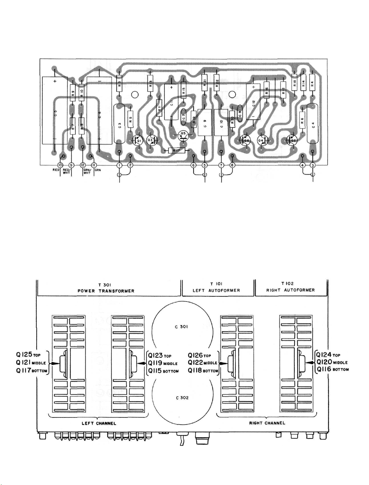
LOCATION OF TRANSISTORS NOT ON PRINTED CIRCUIT BOARDS
Page 5

INPUT
SECTION PRINTED CIRCUIT BOARD
043-795
HEAVY LINE SHOWS PRIMARY SIGNAL PATH
INPUT SECTION
MC
2I05
154-292
Page 6

LEFT CHANNEL
POWER OUTPUT SECTION PRINTED CIRCUIT BOARD
043-805
RIGHT CHANNEL
POWER OUTPUT SECTION PRINTED CIRCUIT BOARD
043-805
Page 7

Page 8

OUTPUT
POWER
366
154-
SECTION
2105
MC
Page 9

METER SECTION PRINTED CIRCUIT BOARD
METER SECTION
MC
2105
154-294
Page 10

SCHEMATIC NOTES
1. Unless otherwise specified: Resistance values are in ohms, 1/2 watt, and 10% tolerance;
capacitance values smaller than 1 are in microfarads (µf) ; capacitance values greater
than 1 are in picofarads (pF); inductors are in microhenries (µH).
2.
Printed
I 3. The heavy lines on the schematics denote the primary signal path.
4. The terminal numbering of rotary switches is for reference only.
5. All voltages indicated on the schematics are measured under the following conditions:
6. R125, R126, R127, and R128 are 2.7K in early units.
7. R215 and R216 are 1.2K and R217 and R218 are 22K in early units.
8. In
9. In
10.
C125
11. R137f R138, R141, and Rl42 are 75ohm 9W 10% (part No. 139-070) and R119 and R120 are 2751
12. In
13. In
14.
R155
15.
R109,
16. In
No's from 10M40 to 23M25, C117 and Cll8 are not used.
17. In
circuit
circled
a. Use of an 11 megohm impedance VTVM.
b. All voltages ±10% with respect to chassis ground.
c. Ho signal at input terminals.
d. AC input at 117 volts AC, 50/60Hz.
e. Front panel controls at:
C109. and C110 (part No. 064-044) are .047; The emitter of Q113 and Q114 is connected as
shown
R147, R148, R149, and R150 are .15W (part Ho. 139-055); pins Ho. 12 and 9 on PC boards
are
in early units.
(part No. 076-010) are not used.
connected
numbers
Left Gain
Meter Range
Right Gain
Speakers
Power
units
with
by the
units with
connected
and
units
with
units
and
R156
110 is 47K in
units
with
units
with
dotted
C126
with
as
board
on the
serial
serial
as
shown
are
serial
serial
shown
are
8.2ohm
serial
serial
components
dotted
FULLY CCW
OFF
FULLY CCW
ON
OH
No's below
line;
R139
No's below 11M93: Rl59
by
used
in
No's below
No's
by
below
dotted
10% in
units
with
No' a
below
No's below
lines
and
dotted
units
line.
serial
are
outlined
correspond
10M40:
Rl40 {part
line.
with
20M01;
20M50
units
10M40;
23M25,
serial
R107, R108, C105,
R161
with
No's
C117
C115
on the
C111, C112, C113,
and
No's
and
serial
from
and
and
to the
Ho.
139-061)
R160
from
R162
No's
11M93
Cll8
C116
schematics
numbers
are not
11M93
are not
from
to
are
are
by
dotted
on the PC
and
C114,
are
used.
used; R143, R144, R145, R146,
to
13M05.
and
C106
are
used
and pin l4 is
l0M40
to
21M13.
23M25.
.0012.
.0012.
In
lines.
board
are
used; C107, C108,
used;
units
layouts.
ferrite
with
The
aerial
beads
18. Adjust meter calibration controls R213 (left channel) and R214 (right channel) so
output meters indicate +3dB when meter range switch is in the "0" position and the
amplifier is delivering 105 watts output.
METER SECTION PRINTED CIRCUIT BOARD 043-711
Page 11

REPLACEMENT PARTS
All
parts
not
able
from
Replacement
by PART NUMBER from:
Symbol
Number Description
C1,2 Mylar ,22uF 250V
C3,4 Mylar .47uF 250V
C5,6 Elect. 500uF 16V
C9,10 Elect. l0uF 25V NP
C11,12 Elect. 100uF 15V
C101,102 Elect.
C121,122 Elect. 10uF 50V
C201,202 Mylar ..47uF 250V
C203,204
C301 Elect. 39,000uF 40V
C302
Elect.
C303
Elect. 80/80/l50/50uF
D101,102 Si. signal diode
D103,104 Si. reference diode
Dl05,106 Si. signal diode
D107,108 Si. signal diode
D201,202 Ge. signal diode
D203,204 Ge. signal diode
D301,302 Rectifier Assy (Black)
D303,304 Rectifier Assy (Red)
D305
Si.
D306
Si.
P301 Fuse 5 ampere Slo-Blo
L101,102 Choke 75uH
M201,202 Meter (power level)
listed
radio
parts
Mclntosh Laboratory Inc.
Customer Service Department
2
Chambers
Binghamton, Hew York 13903
(telephone 607-723-3512)
Elect.
are
parts
may be
CAPACITORS
330uF
100uF
39,000uF
rectifier
rectifier
common
jobbers.
obtained
Street
200/200/150/150V
DIODES
PUSES
CHOKES
METERS
items
3V
3V
40V
when
obtain-
ordered
Part
Number
064-043
064-045
066-107
066-005
066-127
066-105
066-113
064-045
066-047
066-119
066-119
066-095
070-022
070-040
070-022
070-022
070-003
070-003
043-903
043-904
070-031
070-031
089-007
122-013
124-013
Q1,2
Q3,4
Q5,6
Q101,102
Q103,104
Q105,106
Q107,108
Q109,110
Q111,112
Q113,114
Q115,116
Q115,116
Q117,118
Q117,118
Q119,120
Q119,120
Q121,122
Q121,122
Q123,124
Q123,124
Q125,126
Q125,126
Q201,202
R1, 2
R213,2l4
R117,118
R137,138
R141,
142
R143,144
R145,146
R147,148
R149,150
R159-160
R301,302
- TRANSISTORS
Si. NPN transistor
Si. NPN transistor
Si. PNP transistor
Si. PNP transistor
Si. PNP transistor
Si. NPN transistor
Si. NPN transistor
Si. PNP transistor
Si. NPN transistor
Si. PNP transistor
Si. NPN transistor
(Below
Serial
Si. NPN transistor
(Above
Serial
Si. NPN transistor
(Below
Serial
Si. NPN transistor
(Above
Serial
Si. NPN transistor
(Below
Serial
Si. NPN transistor
(Above
Serial
Si. NPN transistor
(Below
Serial
Si. NPN transistor
(Above
Serial
Si. NPN transistor
(Below
Serial
Si. NPN transistor
(Above
Serial
Si. NPN transistor
(Below
Serial
Si. NPN transistor
(Above
Serial
Si. NPN transistor
POTENTIOMETERS
Gain controls
Meter calibration adjust
Wirewound 3.6K 5% 5W
Wirewound .56 ohms 5W
Wirewound .56 ohms 5W
Wirewound .33 ohms 5W
Wirewound .33 ohms 5W
Wirewound . 33 ohms 5W
Wirewound . 33 ohms 5W
Wirewound .33 ohms 5W
Thermistor
No.
No.
No.
No.
No.
No.
No.
No.
No.
No.
No.
No.
RESISTORS
20M01)
20M01)
20M01)
20M01)
20M01)
20M01)
20M01)
20M01)
20M01)
20M01)
20M01)
20M01)
132-054
132-054
132-031
132-031
132-031
132-515
132-021
132-032
132-038
132-039
132-518
132-541
132-518
132-541
132-517
132-541
132-517
132-541
132-517
132-542
132-517
132-542
132-054
134-191
134-120
139-065
139-061
139-061
139-071
139-071
139-071
139-071
139-071
144-012
Page 12

31
S101
S201
S301
S302,303
SWITCHES
Input coupling switch
Speaker switch
Meter range switch
Power on-off switch
Thermal cut-out
TRANSFORMERS
148-006
146-103
146-109
146-102
153-007
T101,102
T301
Front panel
Front panel end caps
Knobs (all controls )
#1866 (for wording)
#1888 (for meters)
Shelf bracket (right)
Shelf bracket (left)
Mounting template #300
Hardware package
Plastic feet
Shipping carton
Owners manual
Line cord
Output transformer
Power transformer
FRONT PANEL AND TRIM
LAMPS
PANLOC SYSTEM
MISCELLANEOUS ITEMS
043-649
043-693
043-735
018-112
043-253
058-014
058-029
043-678
043-679
038-161
043-691
017-041
043-793
038-163
170-021
5C01106S-M9321JG
Page 13

SCHEMATIC PART
NO.
038-321
 Loading...