

McIntosh MC1502 Owner's Manual
McIntosh Laboratory, Inc. 2 Chambers Street Binghamton, New York 13903-2699 Phone: 607-723-3512 www.mcintoshlabs.com
MC1502
Power Amplifier
Owner’s Manual

Important Safety Information is supplied in a separate document “Important Additional Operation Information Guide”
Thank You
Your decision to own this McIntosh MC1502 Tube
Power Amplifier ranks you at the very top among
discriminating music listeners. You now have “The
Best.” The McIntosh dedication to “Quality,” is
assurance that you will receive many years of musical
enjoyment from this unit.
Please take a short time to read the information in this
manual. We want you to be as familiar as possible
with all the features and functions of your new
McIntosh.
Please Take A Moment
The serial number, purchase date and McIntosh Dealer
name are important to you for possible insurance
claim or future service. The spaces below have been
provided for you to record that information:
Serial Number: _______________________________
Purchase Date: _______________________________
Dealer Name: ________________________________
Technical Assistance
If at any time you have questions about your McIntosh
product, contact your McIntosh Dealer who is familiar
with your McIntosh equipment and any other brands
that may be part of your system. If you or your Dealer
wish additional help concerning a suspected problem,
you can receive technical assistance for all McIntosh
products at:
McIntosh Laboratory, Inc.
2 Chambers Street
Binghamton, New York 13903
Phone: 6 07-723-3512
Fax: 607-724-0549
Customer Service
If it is determined that your McIntosh product is in
need of repair, you can return it to your Dealer. You
can also return it to the McIntosh Laboratory Service
Department. For assistance on factory repair return
procedure, contact the McIntosh Service Department
at:
McIntosh Laboratory, Inc.
2 Chambers Street
Binghamton, New York 13903
Phone: 6 07-723-3515
Fax: 607-723-1917
Table of Contents
Safety Instructions .............................................................. 2
(Separate Sheet) ............................Important Additional
Operation Information Guide
Thank You and Please Take a Moment .......................2
Technical Assistance and Customer Service .............. 2
Table of Contents ........................................................2
Unpacking the MC1502 and Ventilation ..................4-5
General Information ...................................................6
Connector Information ...............................................6
Introduction .................................................................7
Performance Features ................................................. 7
Dimensions .................................................................8
Rear Panel Connections, Fuse Holder and Switches ..9
How to Connect for Operation ............................. 10 -11
Connection Diagram (Separate Sheet) ............Mc1A
Front Panel Controls and Indicators..........................12
How to Operate ......................................................... 13
Specifications ............................................................ 14
Packing Instruction ................................................... 15
Copyright 2020 © by McIntosh Laboratory, Inc.
2

IMPORTANT!
INSTRUCTIONS FOR REMOVAL
OF FOAM INSERT OVER THE
VACUUM TUBES PRIOR TO
CONNECTING THE A.C. POWER
SUPPLY CORD, START ON THE
NEXT PAGE.
3
Unpacking the MC1502
Warning Sheet
Shipping Foam
Hot Surface Tag
Caution: To prevent damage to the MC1502
Vacuum Tubes during shipping,
there is a special foam insert
surrounding the Vacuum Tubes of
the Power Amplifier.
The Foam Insert must be
removed from the MC1502
before connecting the AC
Power Supply Cord to the
Power Amplifier.
Failure to do so has the
potential of a Fire Hazard,
resulting in damage to the
MC1502 and the surrounding
environment.
Follow these instructions for
removal of the packing foam
before connecting the AC
Power Supply Cord to the
MC1502.
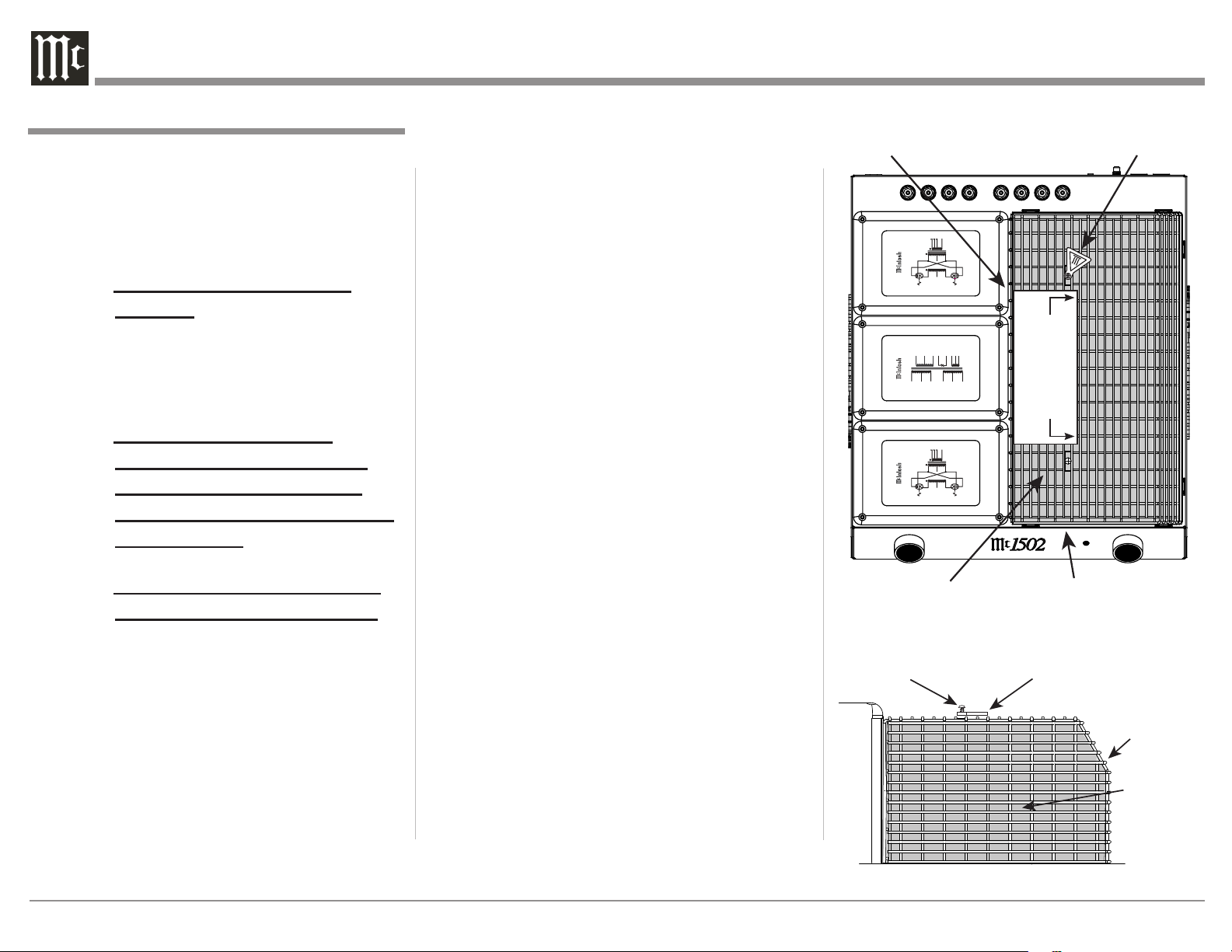
In order to remove the foam insert surrounding the Vacuum Tubes on the MC1502, it
is necessary to temporarily remove the operational Tube Shield Metal Cover. After the foam
insert is removed, the Tube Shield Metal Cover
is to be re-installed for proper and safe operation of the MC1502 Power Amplifier. The Tube
Shield Metal Cover provides protection from
the hazardous voltages inside the MC1502. The
MC1502 has no user serviceable parts, including the Vacuum Tubes. If repairs are needed
they must be performed by an authorized McIntosh Service Agency.
1. Orient the MC1502 so the Front Side of the Power
Amplifier is facing you and remove the Warning
Sheet. Refer to figure 1A.
2. Referring to figure 2B (a partial side view of the
MC1502) to temporarily remove the two screws
and the Hot Surface Tag located on the top of the
Tube Shield Metal Cover by using a Phillips Head
#2 Screw Driver.
3. Carefully lift up and remove the Tube Shield
Metal Cover from the MC1502. Refer to figure
3C.
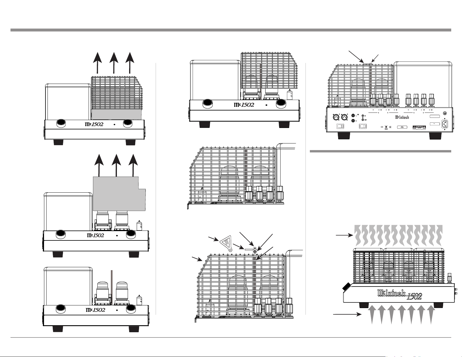
4. Place the Tube Cover and the previously removed
chassis screws in a safe location, as the Tube
Cover will be reinstalled.
5. Carefully lift up and remove the Foam Insert from
the MC1502 exposing the Vacuum Tubes. Refer to
figures 4D and 5E.
6. Carefully place the previously removed Tube
Cover on top of the MC1502. Refer to figures 6F
and 7G.
7. Place the Hot Surface Tag near the top right of the
Metal Tube Cover. Secure it to the Cover of the
MC1502 Chassis using the previously removed
Tube Cover Screws and Retaining Washer. Refer
to figure 8A and the results of figure 9.
Note: Save the Foam Insert and Warning Sheet with
the MC1502 Shipping Carton for future use.
OFF
Screw
UNITY COUPLED OUTPUT TRANSFORMER
POWER TRANSFORMER
UNITY COUPLED OUTPUT TRANSFORMER
4
2
8
COM
+
+
+
YEL
BLK
BLU
RED
15-100kHz
FREQUENCY
POWER 150W
VIO
BRN
ORN
V5 // V7
BLK
V5 // V7
V6 // V8
VIO
BRN
ORN
WHT
WHT
WHT
YEL
BLU
BLK
BLU
RED
RED
GRN
ORN
VIO
BLK/GRY
WHT/VIO
GRY
WHT
4
2
8
COM
+
+
+
YEL
BLK
BLU
RED
15-100kHz
FREQUENCY
POWER 150W
VIO
BRN
ORN
V6 // V8
VIO
BRN
ORN
WHT
WHT
WHT
ON
REFER TO THE OWNER’S
MANUAL FOR INSTRUCTIONS.
MANUAL FOR INSTRUCTIONS.
REFER TO PAGE 3 IN THE MC1502 OWNER’S
WARNING
WARNING
TO AVOID A FIRE HAZARD, THE FOAM INSERT
OVER THE VACUUM TUBES MUST BE REMOVED
PRIOR TO CONNECTING THE AC POWER CORD
AND OPERATING THIS PRODUCT.
TO AVOID A FIRE HAZARD, THE FOAM INSERT
OVER THE VACUUM TUBES MUST BE REMOVED
PRIOR TO CONNECTING THE A.C. MAINS POWER
SUPPLY CORD AND OPERATING THIS PRODUCT.
REMOTE
OFF
ON
Metal Tube Cover
Figure 1A
Hot Surface Tag
Metal
Tube
Cover
Shipping
Foam
Figure 2B
4
Unpacking the MC1502 and Ventilation
Fi
Figure 7G
Figure 8A
Screw
Metal
Tube Cover
Metal Hex Tube
Cover Support
Hot Surface Tag
Washer
Fi
Cool Air
Wa
Figure 3C
Figure 4D
Hot Surface Tag
gure 6F
OFF
NOF
OFF
NOF
ON
ON
Figure 9
BALANCED INPUTS UNBALANCED
BALANCED
INPUT MODE
UNBALANCED
INPUTS
ENABLED
Screw
COM
POWER
CONTROL
AUTO OFF
R OUTPUT
CLASS 2 WIRING
DISABLED
COM
MC1 502
POW ER A MPL IF IER
McINTOSH LABORATORY, INC., BINGHAMTON, NY
HANDCRAFTED IN USA WITH US AND IMPORTED PARTS
L OUTPUT
CLASS 2 WIRING
T8AL 250V
120V 50/60Hz
5.5 AMPS
Ventilation
Adequate ventilation extends the trouble free life of
the MC1502. Always allow air to f low through the
ventilation holes on the bottom of the amplifier and a
means for the warm air to escape at the top. Refer to
figure 10.
Allow at least 19 inches (48.3cm) above the top; 6
inches (15.2cm) for the Front, Rear and Sides; allow
1/2 inch (1.3cm) below the Power Amplifier so the
airf low is not obstructed.
Figure 5E
NOF
NOF
OFF
ON
OFF
ON
rm Air
gure 10
5
 Loading...