

Page 1
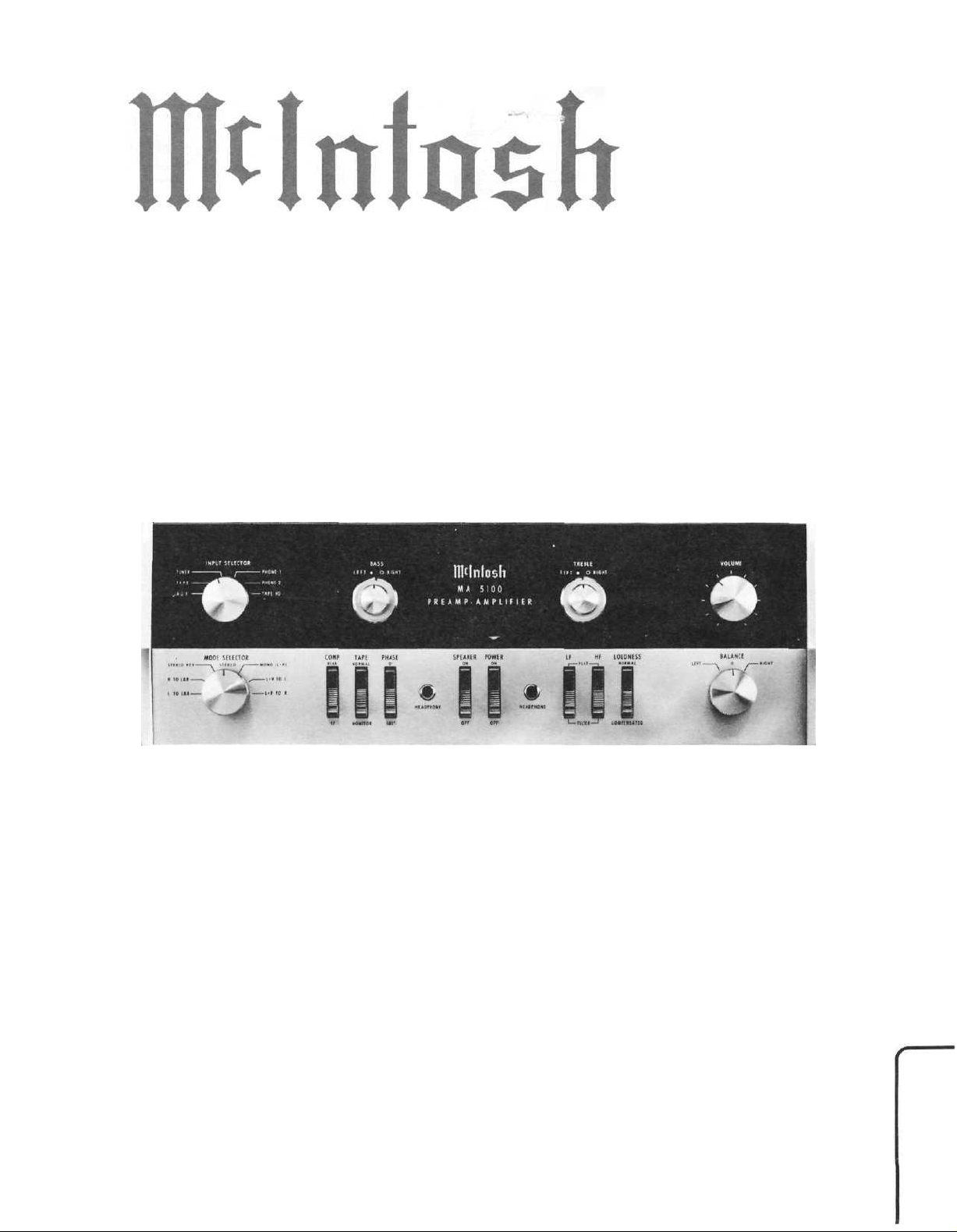
MA
PREAMP - AMPLIFIER
5100
SERVICE INFORMATION
STARTING
MclNTOSH LABORATORY INC. 2 CHAMBERS STREET BINGHAMTON, NEW YORK
WITH
SERIAL
NO.
21HOO
MA 5100
Page 2

MA
5100
ELECTRICAL SPECIFICATIONS
Power Output:
90 watts RMS continuous, 45 watts per channel operating simultaneously into
4 ohm or 8 ohm loads.
60 watts RMS continuous, 30 watts per channel operating simultaneously into
16 ohm loads.
Harmonic Distortion:
Less than 0.25% at rated power output from 20Hz to 20,000Hz with both chan-
nels operating.
Intermodulation Distortion:
Less than 0.25% for any combination of frequencies from 2QHz to 20,000Hz
if instantaneous peak power is 90 watts per channel or less into 4 or 8 ohm
loads and 60 watts per channel or less into 16 ohm loads with both channels
operating.
Frequency Range:
At rated output both channels: ±0.5dB 20Hz through 20,000Hz.
Output Impedance:
4 ohm, 8 ohm, 16 ohm. No impedance switching required.
Internal Impedance/Damping:
Less than .04 ohms; damping factor greater than 100.
Input Sensitivity And Impedance:
Auxiliary, Tape, Tuner, and Tape Monitor: 300mV, 250K ohms.
Phono 1 and Phono 2: 2mV, 47,000 ohms.
Tape Head: 2mV, 1/2 megohm.
Hum And Noise:
High Level Inputs: 75dB below rated output.
Low Level Inputs: 70dB below 10mV input.
Power Amplifier: 90dB below rated output.
Tape Output:
300mV at rated sensitivity, 1.4 volts with 10mV at phono input.
Left Plus Right Output:
Adjustable
Bass Controls:
+18dB at 20Hz.
Treble Controls:
+l8dB at 20,000Hz.
0 to 6
volts from generator impedance
of
less than
5,000
ohms.
HF Filter:
Flat, or 5,000Hz cutoff.
LP Filter:
Plat, or 50Hz cutoff.
Power Requirements;
117 volts AC, 50-60Hz, 70 watts at zero signal output, 200 watts at rated
output.
Page 3
MA
5100
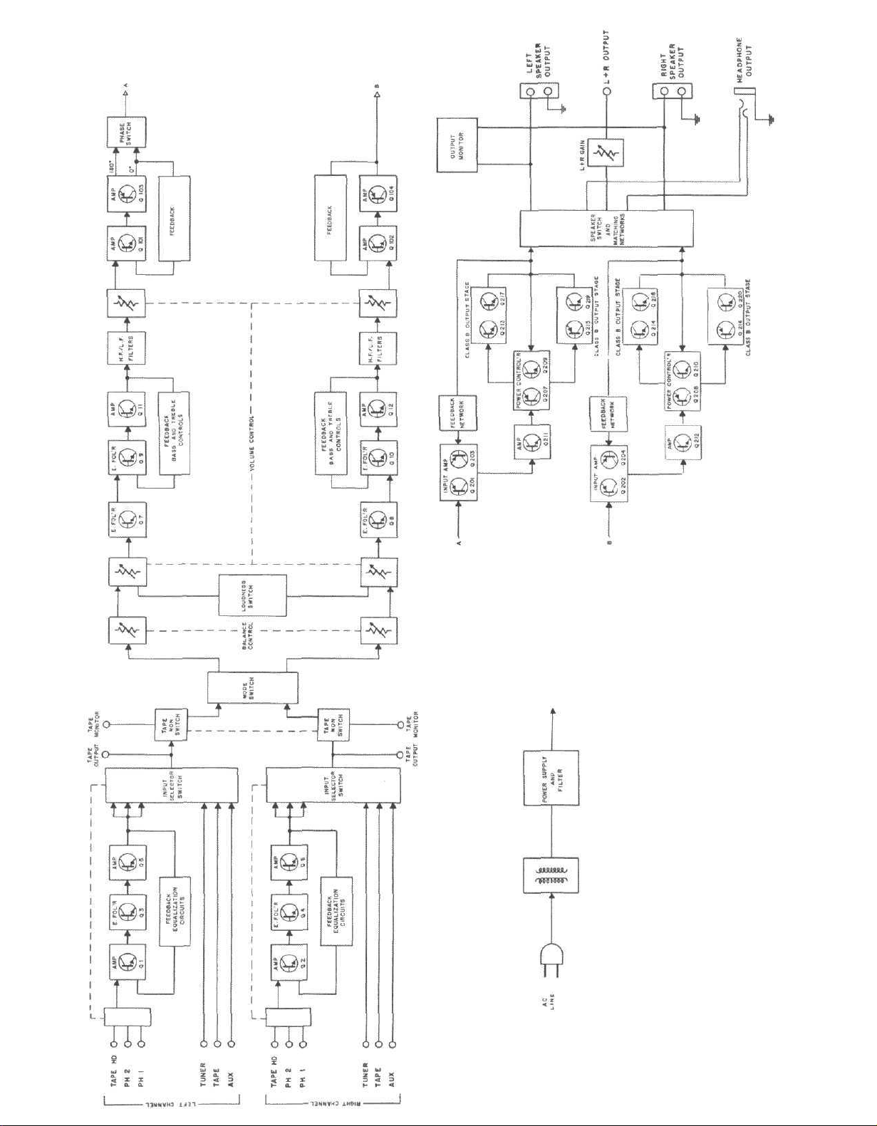
DIAGRAM
BLOCK
5100
MA
Page 4
MA
5100
043-989
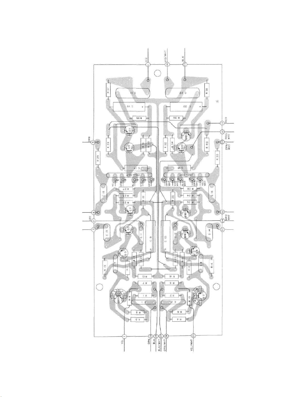
PREAMP. SECTION PRINTED CIRCUIT BOARD
Page 5

HEAVY
LINE
SHOWS
PRIMARY
SIGNAL PATH
PREAMP. SECTION
MA 5100 154-411
Page 6

POWER OUTPUT
HEAVY LINE SHOWS PRIMARY SIGNAL PATH
SECTION
MA 5100 154-376
Page 7

MA
5100
OUTPUT MONITOR PRINTED CIRCUIT BOARD
( NOTE 1 )
043-821
LEFT CHANNEL POWER OUTPUT SECTION PRINTED CIRCUIT BOARD 043-919
RIGHT CHANNEL POWER OUTPUT SECTION PRINTED CIRCUIT BOARD
043-919
Page 8

MA
5100
FILTER SECTION PRINTED CIRCUIT BOARD 043-990
FILTER SECTION PRINTED CIRCUIT BOARD
043-990
FILTER SECTION
MA5100 154-410
Page 9

SCHEMATIC NOTES
Unless otherwise specified: Resistance values are in ohms, 1/2 watt, and 10%
tolerance;
values greater than 1 are in picofarads (pF) ; inductors are in microhenries (µH).
Printed
The
circled
layouts.
The
heavy
The terminal numbering of rotary switches is for reference only.
All
voltages
tions :
a. Use of an 11
b. All
c. No signal at input terminals,
d. AC
e. Front panel controls at:
1. In
2. In
3. In
4. In
5. In
6. In
7. In
8. In
9. In
10. In
11. In
12. In
F202, F203j
capacitance
circuit
voltages
input
Input
Mode Selector
All other controls in normal position.
units
used.
units
R255
are 120
(134-120)
dotted
early
units
C216, C217, and C2l8 are not used; C227, C228, C229, C230, C231, and C232
are used; R229 & R230 are 100 ohms; C201 & C202 are 330pF.
early
units
(part number 070-022).
units
R314 are not used.
early
units
&
R234
units
not used.
units
units
board
numbers
lines
on the
indicated
megohm
±10%
at 117
Selector
with
with
ohms;
are
line;
C221 & C222
units,
with
units,
with
with
units,
with
are 220
with
with
with
and
serial
serial
serial
serial
serial
values
components
on the
volts
serial
serial
used;
C5 & C6
serial
C207 & C208
C308 & C309
ohms;
serial
F204
dotted
schematics denote
on the
input
with
respect
AC,
AUX
STEREO
numbers below
numbers below 44H50:
transistors
the
emitter
were
numbers below 30H15: L201, L202, R241,
numbers below 30H30: D201 & D202
numbers below 28H00:
numbers below 24H05:
C211, C212, C213,
numbers below
numbers below 22H00:
No's below 54H60:
are 3A
smaller
are
outlined
lines
schematics
impedance
to
50/60Hz.
Q205
are
of
used.
39pF.
were
were
fuses.
200µF,
10,000µF,
than
1 are in
on the
correspond
the
primary
are
measured
VTVM,
chassis
46H01,
Q2l5 & Q216
23H7S:
(Part
ground.
Volume
Power
the
& Q206
R256 & R25?
(132-021)
3V
(part
C3,
40V
R237 & R238
and
C2114
D211, D212, D213,
R227 & R228
R254
and
Ho.
089019)
microfarads
schematics
to the
output
is
C4} C5, C6, R9,
(part
numbers
signal
MAX
ON
connected
number 066-086).
are
R255
path.
under
the
monitor
are not
and
pots R221 & R222
were
number 066-090).
are .47
.01µF.
were
1K,
are 18 and
(mfd);
by
following
PC
as
R242,
two
and
capacitance
dotted
of the PC
board
used;
shown
C215,
diodes
R10,
and
ohms;
D214
10%,
F201,
lines.
condi-
is not
R254 &
by the
R233
are
1W,
board
MA
5100
LOCATION OF TRANSISTORS NOT ON PRINTED CIRCUIT BOARDS
Page 10

MA
5100
SUPPLY
POWER
SECTION
154-331
5100
MA
Page 11

REPLACEMENT PARTS
All parts not listed are common items obtain-
able from radio parts jobbers.
Replacement parts may be obtained when ordered
by PART NUMBER from:
Mclntosh Laboratory, Inc.
Customer Service Department
2 Chambers Street
Binghamton, New York 13903
(telephone 607-723-3512)
Symbol
Number
C1 ,2
C7,8
C9 ,10
C11 , 12
C13,
14
C15,
16
C17,
18
C19,20
C21 ,22
C23,24
C101 , 102
C103,
104
C107,
108
C11 1
C1 12, 113
C203,204
C207,208
C21 1
,212
C213,214
C223,224
C304
C305
C306
C307
C308
C309
D201 ,202
D203,204
D205,206
D207,208
D209,210
D21 1
,212
D213,214
CAPACITORS
Description
Mylar .22µF 250V
Mylar .1µF 250V
Elect. 100µF 12V
Mylar .1µF 250V
Mylar .1µF 250V
Mylar .47µF 75V
Mylar .47µF 250V
Elect.
100µF
Mylar .47µF 250V
Mylar .22µF 200V
Mylar . 1 µF 250V
Mylar .01µF 250V
Mylar .22µF 250V
Ta. Elect. 1µF 35V
Ta. Elect. 1.5µF 35V
Elect.
100µF
Elect.
180µF
Mylar .047µF 250V
Mylar .047µF 250V
Elect. 10µF 25V
Elect. 80/80/150/50µF 066-103
Elect. 200/500µF
Elect. 200/500µF
Elect. 100µF 12V
Elect. 9300µF 45V
Elect. 9300µF 45V
DIODES
Si. reference diode
Si. rectifier
Si. rectifier
Si. signal diode
Si. signal diode
Si. rectifier
Si. rectifier
12V
12V
3V
200/200/150/150V
100/50V
-100/-75V
Part
Number
064-043
064-037
066-127
064-037
064-037
064-039
064-045
066-127
064-045
064-087
064-038
064-040
064-043
066-091
066-092
066-127
066-111
064-044
064-044
066-005
066-099
066-093
066-127
066-106
066-106
070-040
070-030
070-030
070-022
070-022
070-031
070-031
D301
D302
D303
D304
D305
D306
D307
D308
D309
F201 ,202
F203,204
F301
L201 ,202
Q1,2
Q3,4
Q5,6
Q7,8
Q9, 10
Q11,12
Q101 , 102
Q103,
104
Q201 ,202
Q203,204
Q207,208
Q209,210
Q211
,212
Q211
,212
Q213,214
Q215,216
Q217,218
Q219,220
R53
R58
R63
R63
R64
R64
R247
Si. rectifier
Si. rectifier
Si. rectifier
Si. rectifier
Si. rectifier
Si. rectifier
Si. rectifier
Si. rectifier
Si. rectifier
FUSES
Fuse 4A (SFE-4)
Fuse 4A (SFE-4)
Fuse 2.5A Slo-Blo
CHOKES
Choke 2µH
TRANSISTORS
Si. NPN transistor
Si. NPN transistor
Si. NPN transistor
Si. NPN transistor
Si. NPN transistor
Si. NPN transistor
Si. NPN transistor
Si. PNP transistor
Si. PNP transistor
Si. PNP transistor
Si. NPN transistor
Si. PNP transistor
Si. NPN transistor (for
units above 22H60)
Si. NPN transistor (for
units below 22H60)
Si. NPN transistor
Si. PNP transistor
Si. NPN transistor
Si. NPN transistor
POTENTIOMETERS
Balance control
Volume Control
Bass control (w/flat shaft)
Bass
control
shaft)
Treble control (w/flat
shaft)
Treble control (w/knurled
shaft)
L & R adjust
(w/knurled
MA
5100
070-031
070-031
070-031
070-031
070-041
070-041
070-041
070-041
070-030
089-021
089-021
089-015
122-064
132-041
132-041
132-051
132-041
132-057
132-051
132-057
132-029
132-029
132-029
132-021
132-032
132-515
132-022
132-521
132-527
132-533
132-533
134-035
134-033
134-172
134-162
134-173
134-163
134-063
Page 12

MA
5100
R231
R237,238
R239,240
R250,251
R301
R302,303
R307
R308
R311
R312
R313
S1
S2
S3
S4
S5
S101
S102
S103
S201
S301
S302
S303
,232
RESISTORS
Wirewound 3 . 6k 5W
Wirewound .33 ohms 5W
Wirewound .47 ohms 5W
Wirewound 200 ohms 5W
Wirewound 100 ohms 5W
Wirewound 220 ohms 5W
Wirewound 100 ohms 5W
Wirewound 220 ohms 5W
Wirewound 7.5 ohms 5W
Wirewound 500 ohms 5W
Wirewound 220 Ohms 5W
SWITCHES
Input selector switch
Compensation switch
Tape monitor switch
Mode selector switch
Loudness switch
L F switch
HF switch
Phase switch
Speaker switch
Power switch
Thermal cut out
Thermal cut out
139-013
139-036
139-050
139-009
139-008
139-009
139-008
139-009
139-010
139-011
139-009
146-035
148-019
148-012
146-105
148-019
148-019
148-019
148-019
148-012
148-005
153-007
153-007
Treble knob (front) - for
knurled shaft
Bass knob (rear)
Bass knob (front) - for
flat shaft
Bass knob (front) - for
knurled shaft
LAMPS
Panel
illumination
Switch
Shelf bracket {right)
Shelf bracket (left)
Mounting template #100
Hardware package
Plastic feet
Shipping carton
Owners manual
Line cord
Shorting plug
Fuseholder
indicator
MOUNTING SYSTEM
MISCELLANEOUS ITEMS
#1864
#334
090-008
090-009
043-625
090-008
058-028
058-003
043-234
043-235
038-179
043-557
017-041
043-727
038-129
170-021
127-001
178-001
T301
TR201 ,202
SB201 ,202
TRANSFORMERS
Power transformer
THYRISTORS & TRIGGERS
Triac
Bilateral switch
MODULES
Tone Control module
Compensation module
FRONT PANEL & TRIM
Front panel
Front panel end cap {right)
Front panel end cap (left)
Volume control knob
Balance control knob
Input control knob
Mode selector knob
Treble knob (rear)
Treble knob (front) - for
flat shaft
043-551
131-001
131-002
130-007
130-026
043-725
018-043
018-044
043-253
043-253
043-253
043-253
090-009
043-625
•
MA
5100
SCHEMATIC PART
NO.
038-376
15C1114S6-M9376
BE042004
 Loading...