


MAXDATA PLATINUM 1500R
Server Case
User’s Manual
MAXDATA PLATINUM Server Case User’s Manual
1

2
MAXDATA PLATINUM Server Case User’s Manual

Part 1 Server Case
MAXDATA PLATINUM Server Case User’s Manual
3

4
MAXDATA PLATINUM Server Case User’s Manual

Content
1 Chassis Description ..................................................................................... 9
What Your Kit Includes ........................................................................................................ 9
Items You Must Purchase Separately .................................................................................. 9
Feature Summary ................................................................................................................10
System Components ......................................................................................................10
Chassis Front Panel and Peripheral Bays ........................................................................ 11
Chassis Back I/O Ports and Features .............................................................................. 11
Front Panel Controls and Indicators ................................................................................12
Peripherals ...........................................................................................................................14
Hard Disk Drives .............................................................................................................14
Hot Swappable SCSI Hard Drives ...........................................................................14
ATA Hard Drives .....................................................................................................14
Flex Bay ..........................................................................................................................15
Power Supply ...................................................................................................................... 15
System Cooling ...................................................................................................................15
Chassis Security ..................................................................................................................15
Locking and Unlocking the Bezel ....................................................................................15
2 Assembling the System ..............................................................................17
Before You Begin ................................................................................................................. 17
Supplies Needed ............................................................................................................ 17
Installation/Assembly Safety Instructions ...........................................................................18
Use Only for Intended Applications ................................................................................18
Checking the Power Cord ...............................................................................................18
Warnings and Cautions .................................................................................................. 19
Installing System Components ...........................................................................................20
Preparing the Chassis .................................................................................................... 20
Removing the Cover ...............................................................................................20
Removing the Riser Cards ..................................................................................... 21
Removing the Fan Module .....................................................................................22
Removing the Power Supply ..................................................................................23
Removing the Drive Carriers .................................................................................. 24
Installing System Components ...........................................................................................25
Installing the Server Board .............................................................................................25
Installing the Power Distribution Board ..........................................................................27
Installing the Backplane Board ....................................................................................... 28
Installing the Power Supply Module ...............................................................................29
Installing the Fan Module ...............................................................................................30
Cable Routing ......................................................................................................................31
SCSI System Cable Routing ........................................................................................... 31
ATA System Cable Routing .............................................................................................32
Installing the Fan Module ...............................................................................................34
Installing the Air Baffle ................................................................................................... 35
Installing the Power Cord and Strain Relief Strap ...........................................................36
Adding Components to the Server Board ...........................................................................36
MAXDATA PLATINUM Server Case User’s Manual
5

Installing Optional Peripherals ..............................................................................................37
Installing a PCI Card on a Riser Card...............................................................................37
Installing a Riser Card on the Server Board ....................................................................38
Installing a Hard Drive .....................................................................................................39
Installing a CD-ROM Drive/FDD Module.........................................................................41
Installing a Bezel .............................................................................................................42
3 Installing the System in a Rac k .....................................................................43
Equipment Rack Precautions ................................................................................................43
4 Working Inside Your Server............................................................................45
Tools and Supplies Needed ..................................................................................................45
Safety: Before You Remove the Cover ..................................................................................45
Warnings and Cautions.........................................................................................................45
Lithium Battery Replacement .........................................................................................45
Air Baffle...............................................................................................................................47
Removal ..........................................................................................................................47
Installation.......................................................................................................................47
Replacing a Hard Drive .........................................................................................................48
Replacing a CD-ROM Drive/FDD Module.............................................................................50
Replacing a PCI Add-in Card .................................................................................................50
Replacing the Power Supply Module....................................................................................52
Replacing the Fan Module....................................................................................................53
Replacing a Backplane Board................................................................................................54
Replacing a Power Distribution Board...................................................................................55
Replacing a Front Panel Board ..............................................................................................56
Replacing a Server Board .....................................................................................................57
A Regulatory and Cer tification Inf ormation .....................................................59
Product Regulatory Compliance ...........................................................................................59
Product Saf ety Compliance.............................................................................................59
Product EMC Compliance...............................................................................................59
Product Regulatory Compliance Markings......................................................................59
Electromagnetic Compatibility Notices.................................................................................60
FCC Verification Statement (USA)...................................................................................60
ICES-003 (Canada) ..........................................................................................................60
Europe (CE Declaration of Conformity) ...........................................................................61
VCCI (Japan) ....................................................................................................................61
Regulated Specified Components ........................................................................................61
B Safety Warnings .............................................................................................63
WARNUNG: Deutsch...........................................................................................................64
WARNING: English (US) ......................................................................................................66
AVERTISSEMENT: Français .................................................................................................68
6
MAXDATA PLATINUM Server Case User’s Manual

Figures
1. System Components ......................................................................................................10
2. Chassis Front ................................................................................................................. 11
3. Chassis Back ................................................................................................................. 11
4. Controls and Indicators .................................................................................................. 12
5. Optional Peripherals .......................................................................................................14
6. Removing the Cover.......................................................................................................20
7. Removing a Riser Card..................................................................................................21
8. Removing the Fan Module .............................................................................................22
9. Removing the Power Supply ..........................................................................................23
10. Removing a Drive Carrier from a Drive Bay.................................................................. 24
11. Mounting the Server Board SCB2..................................................................................26
12. Installing the Power Distribution Board .........................................................................27
13. Installing the Backplane Board ...................................................................................... 28
14. Installing the Power Supply ...........................................................................................29
15. Installing the Fan Module ..............................................................................................30
16. Cable Routing - SCSI System ........................................................................................31
17. Cable Routing - ATA System ..........................................................................................32
18. Installing the Fan Module ..............................................................................................34
19. Installing the Air Baffle...................................................................................................35
20. Installing the Power Cord and Strain Relief Strap..........................................................36
21. Installing a PCI Card in a Riser Card ..............................................................................37
22. Installing a Riser Card on the Ser ver Board ..................................................................38
23. Removing an Air Baffle from a Drive Carrier.................................................................39
24. Att aching a Drive to a Carrier........................................................................................40
25. Installing a CD-ROM Drive/FDD Module ......................................................................41
26. Installing the Bezel ........................................................................................................42
27. Removing the Air Baffle .................................................................................................47
28. Removing a Carrier and Hard Drive from a Drive Bay..................................................48
29. Removing a Hard Drive from a Carrier..........................................................................49
30. Removing a CD-ROM Drive/FDD Module ....................................................................50
31. Removing a Riser Card..................................................................................................51
32. Removing the Power Supply Module ............................................................................52
33. Replacing the Fan Module.............................................................................................53
34. Replacing the Backplane Board ....................................................................................54
35. Replacing the Power Distribution Board........................................................................55
36. Replacing the Front Panel Board ...................................................................................56
37. Removing the Server Board..........................................................................................57
Tables
1. Control Button Functions ................................................................................................13
LED Indicator Status ......................................................................................................13
2.
MAXDATA PLATINUM Server Case User’s Manual
7

8
MAXDATA PLATINUM Server Case User’s Manual

1 Chassis Description
Your server chassis kit comes with the front panel board and two driv e carriers installed. The
fan module, power supply, and power distribution board are installed for shipment, but you
must remove and reinstall them in the proper sequence during system assembly.
T o complete the sy stem, you must purc hase some items separately (see below). Bef ore you
purchase, decide if you want an ATA-100 based system or a SCSI based system and select
components accordingly.
What Your Kit Includes
Your kit includes the following components:
1U rack-mount chassis featuring:
Two hard drive bays with carriers and drive blanks (baffles)
One flex bay with blank filler panel and plug
One 250W SSI PFC non-redundant power supply
Two PCI riser cards for use with the Intel Server Board SCB2
One fan module consisting of five 40-mm fans for system cooling
One power distribution board
One power cord (U.S. version)
One internal USB cable, (connecting server board to front panel board)
One internal flex circuit cable, 100-pin (connecting server board to backplane board)
One internal front panel cable, 34-pin (connecting front panel board to backplane
board)
One CD-ROM containing documentation for your chassis
Mounting screws (server and backplane boards)
Bracket mounting kit
Items You Must Purchase Separately
The following components must be purchased separately:
Front bezel (optional)
Intel Server Board SCB2 (SCSI or ATA)
®
Minimum of one Intel
PC-133 SDRAM memory DIMMs
Backplane board (SCSI or ATA)
Hard disk drives (HDD)
Slimline CD-ROM drive/floppy disk drive module (optional)
PCI add-in cards
Other peripheral devices
Rack Mount Rail Kit
MAXDATA PLATINUM Server Case User’s Manual
Pentium® III processor with 512K cache support (FC-PGA2)
9
Feature Summary
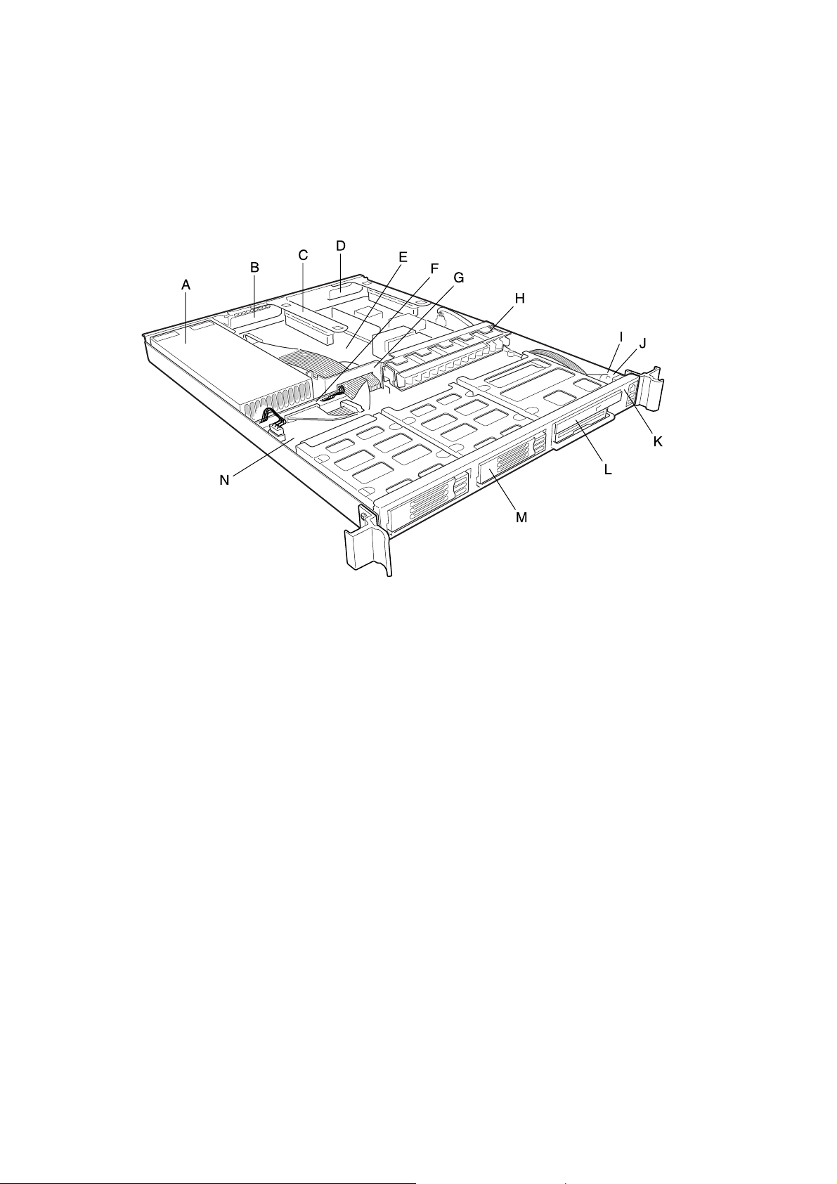
System Components
A. Power supply
B. PCI card bracket (full-length)
C. Riser card assembly
D. PCI card bracket (low-profile)
E. Server board (accessory to system)
F. Power distribution board
G. Air baffle
H. Fan module
I. Front panel board
J. Intrusion switch
K. Control panel
L. Flex bay (optional CD-ROM drive/FDD module shown)
M. Hard drive bay (one of two)
N. Backplane board
Figure 1. System Components
10
Description of the case
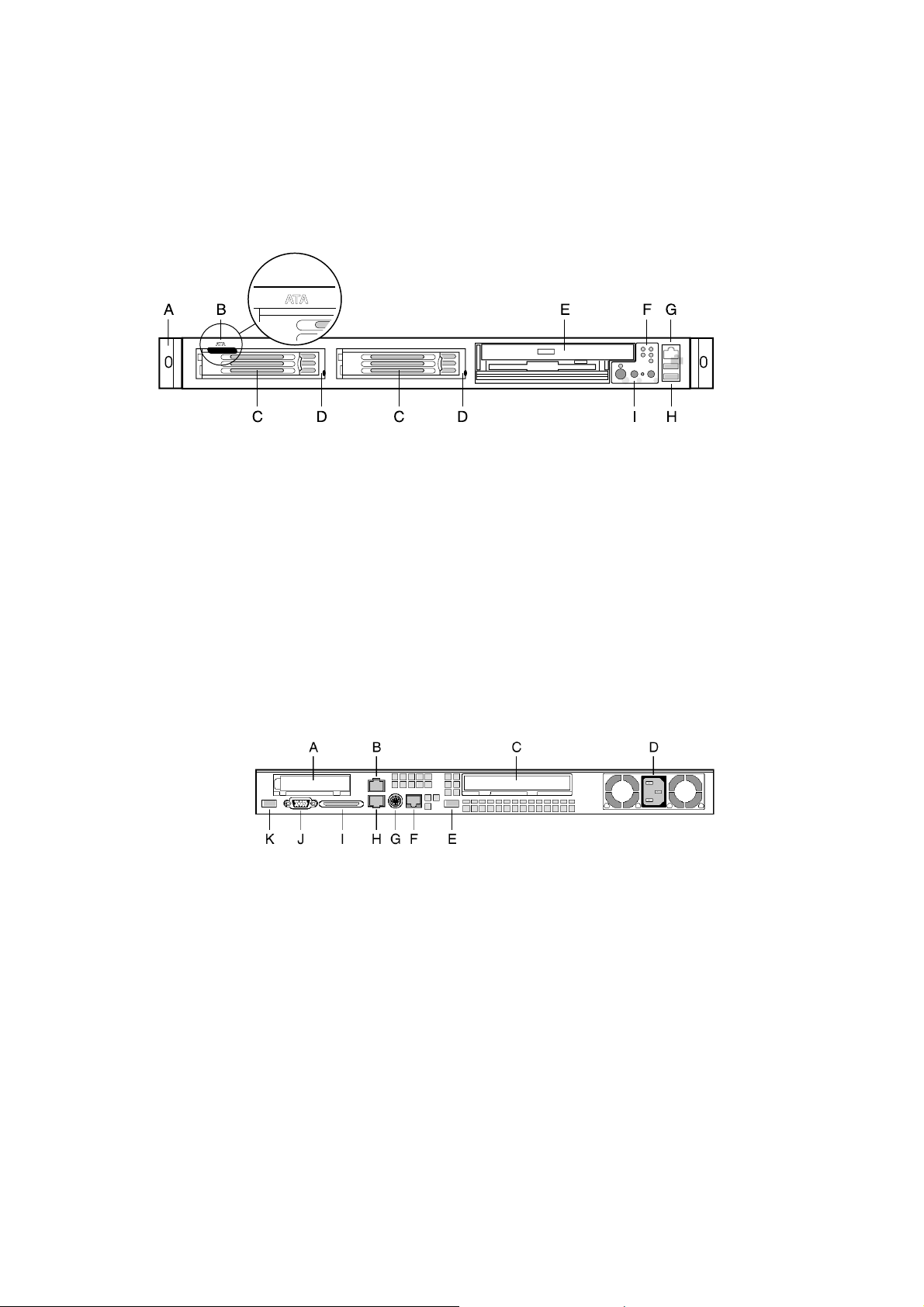
Chassis Front Panel and Peripheral Bays
To access the system controls and peripherals when a front bezel is installed, grasp the
bezel and gently pull it towards you until it unsnaps from the chassis.
A. Chassis handles (2)
B. Drive-type designator (ATA system only)
C. Drive bay (1-inch)
D. HDD activity/fault Indicator
E. Flex bay (optional CD-ROM drive/FDD module shown)
F. Front panel indicator lights
G. RJ-45 serial port
H. USB connectors 1 and 2
I. System controls
Figure 2. Chassis Front
Chassis Back I/O Ports and Features
A. PCI card bracket (low profile)
B. RJ-45 NIC 2 connector
C. PCI card bracket (full-height)
D. Power supply
E. USB connector
F. RJ-45 serial port
G. PS/2† mouse/keyboard connector
H. RJ-45 NIC 1 connector
I. SCSI connector (SCSI version only;
J. Video connector
K. USB connector
Green Status LED
Yellow Status LED
Green Status LED
Yellow Status LED
shown with chassis knockout removed)
Figure 3. Chassis Back
MAXDATA PLATINUM Server Case User’s Manual
11
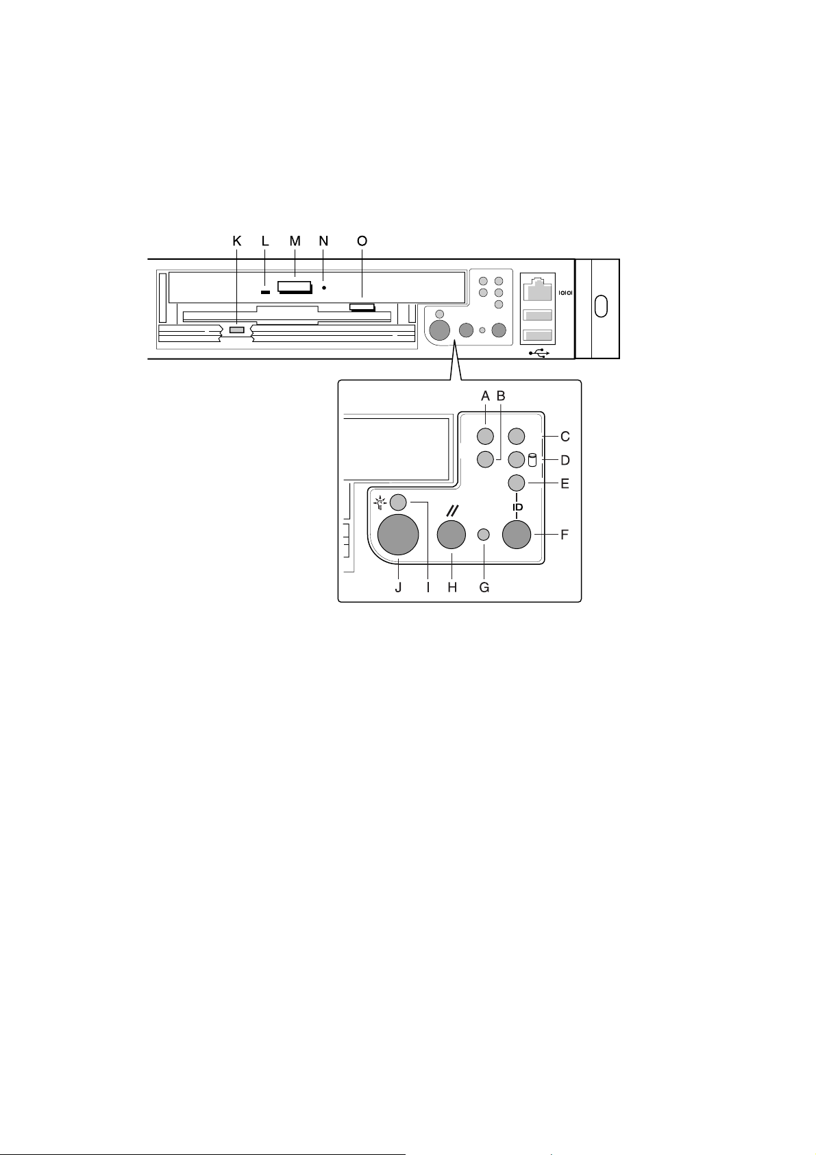
Front Panel Controls and Indicators
Shown with optional CD-ROM drive/floppy disk drive installed.
A. NIC 1 activity LED
B. NIC 2 activity LED
C. System status LED
D. Fixed disk drive status LED
E. ID LED
F. ID button
G. NMI button (tool assisted)
H. Reset button
I. Power/sleep LED
J. Power/sleep button
K. FDD activity LED
L. CD-ROM activity LED
M. CD-ROM drive eject button
N. (Tool assisted) Manual CDROM drive eject button
O. FDD eject button
Figure 4. Controls and Indicators
12
Description of the case
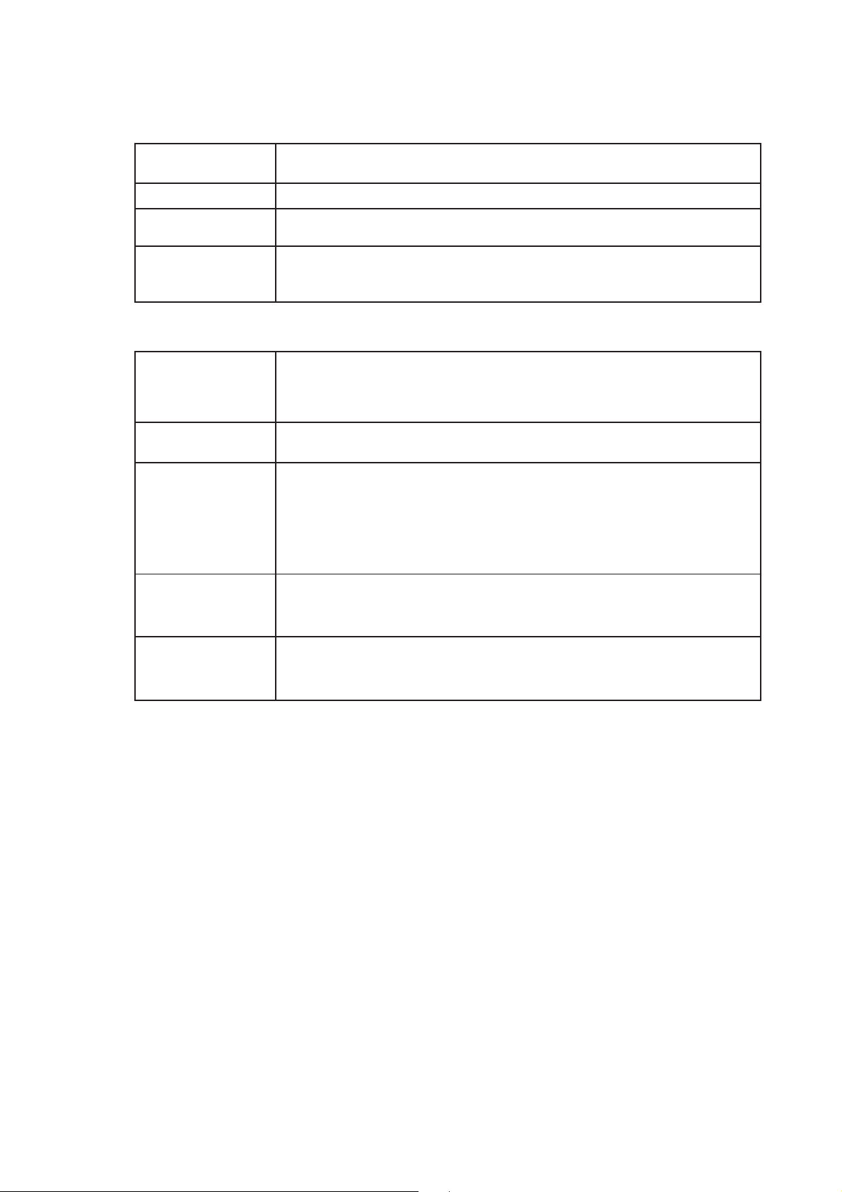
Table 1. Control Button Functions
Power/Sleep button Toggles the system power on/off. Sleep button for ACPI compatible operating
systems.
Reset button Reboots and initializes the system.
NMI button Pressing the recessed button with a paper clip or pin issues a non-maskable inter
rupt and puts the server into a halt state for diagnostic purposes.
ID button Toggles the front panel ID LED and the baseboard ID LED on/off. The baseboard
ID LED is visible through the rear of the chassis and allows you to locate the server
you’re working on from behind a rack of servers.
Table 2. LED Indicator Status
Power/sleep LED Continuous green light indicates the system has power applied to it.
Blinking green light (Note 4) indicates the system is sleeping.
No light indicates the system does not have power applied to it (other than 5 V
standby power).
NIC 1 activity LED Continuous green light indicates activity between the system and the network to
NIC 2 activity LED which it is connected.
System status LED Continuous green light indicates the system is operating normally.
Blinking green light indicates the system is operating in a degraded condition.
Continuous amber light (Note 1) indicates the system is in a critical or nonrecover
able condition.
Blinking amber light (Note 1) indicates the system is in a non-critical condition.
No light indicates POST/system stop.
Fixed disk drive Random blinking green light indicates fixed disk drive activity (SCSI or IDE).
status LED Continuous amber light (Note 2) indicates fixed disk drive fault (SCSI or IDE).
No light (Note 3) indicates no fixed disk drive activity nor fault (SCSI or IDE).
ID LED Continuous blue light indicates ID button is depressed or light is turned on by
software.
No light indicates ID button is not depressed.
✏ NOTES:
1. The Amber status takes precedence ov er the Green stat us. When the Amber LED is on
or blinking, the Green LED is off.
2. In order for a hard disk fault indication to occur, either an Intelligent Platform Manage-
ment Interface (IPMI) based satellite management controller must send a Set Fault Indi-
cation command to the Baseboard Management Controller (BMC), or the system board
must be used with the 1U SR1200 hot swappable backplane.
3. Also off when the system is powered off or in a sleep state.
4. The Po wer LED sleep indication is maintained on standby by the c hipset. If the system is
powered down without going through BIOS , the LED state in ef fect at the time of po wer
off will be restored when the system is powered on until the BIOS clears it. If the sys-
tem is not powered down normally, it is possible that the Power LED will be blinking at
the same time that the System Status LED is of f due to a f ailure or configuration c hange
that prevents the BIOS from running.
MAXDATA PLATINUM Server Case User’s Manual
13
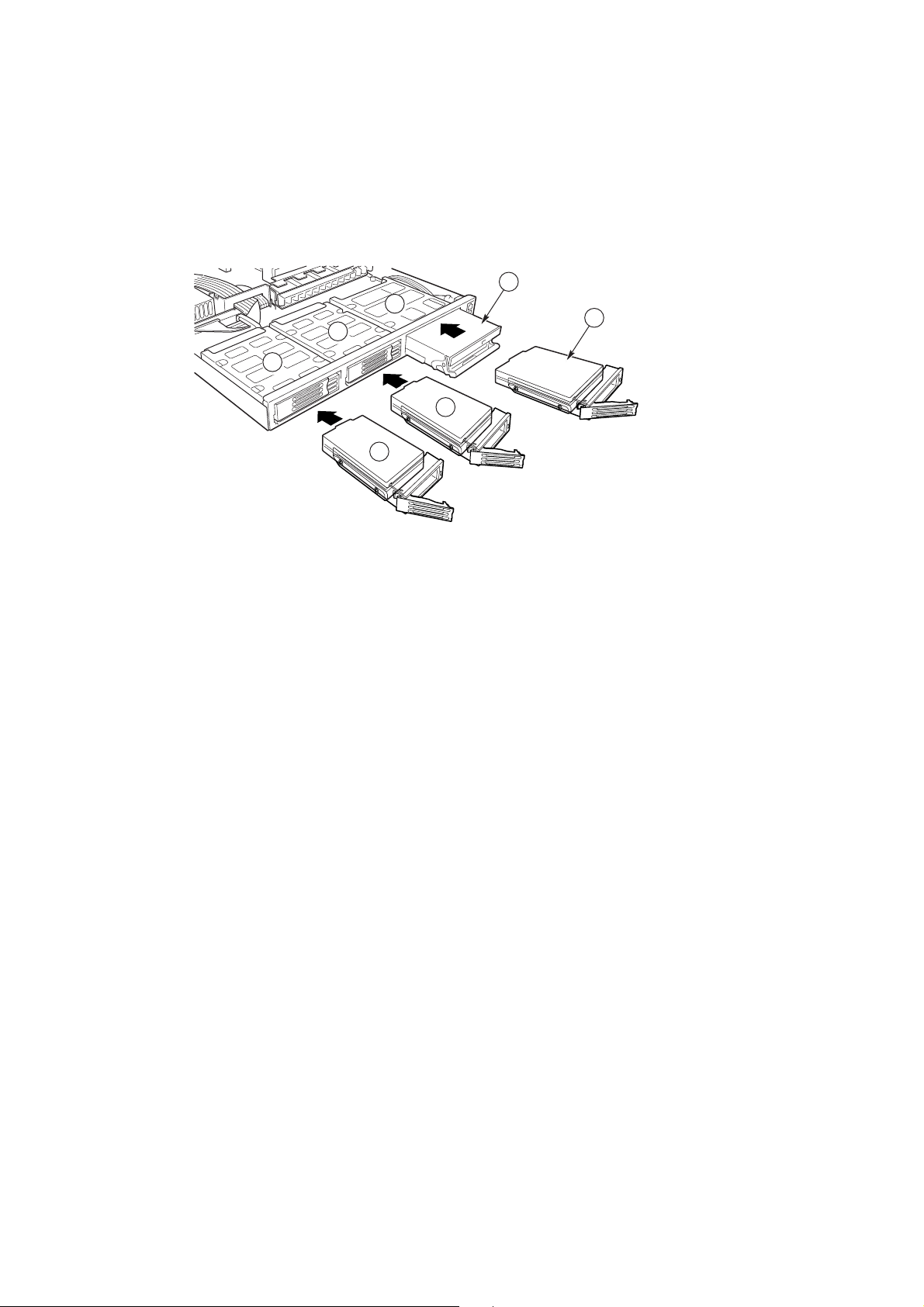
Peripherals
The c hassis provides f or a variety of peripherals that can be purc hased separately and added
to the system. The following describes the available options.
C
B
A
A
E
E
A. Hard drive bays
B. Flex bay
C. Slimline CD-ROM drive/floppy disk drive module
D. Hard disk drive
E. Hard disk drive
Figure 5. Optional Peripherals
D
Hard Disk Drives
The c hassis ships with two drive carriers f or mounting HDD in the hard drive bay s. T hese can
be either SCSI or ATA, depending on what type of system was configured. For information
on how to install these drives, see “Installing a Hard Drive” on 39.
✏ NOTE
Drives can consume up to 17 watts of po w er each. Drives must be specified
to run at a maximum ambient temperature of 50
Hot Swappable SCSI Hard Drives
In a SCSI system, the SCSI hard drives are hot swappable. When a drive fails, the SCSI
backplane detects the failure, reports it, and powers down the failed drive. The drive fault
LED becomes a continuous amber light. Af ter the f ailed driv e is remo ved and a ne w driv e is
inserted, there is a short wait before power is applied to the drive and the drive fault LED
becomes a random blinking green light.
ATA Hard Drives
In an ATA system, the hard drives are NOT hot swappable.
CAUTION
ϒC.
ATA hard drives are NOT hot swappable. Before replacing an ATA hard drive, you must first
take the server out of service, turn off all peripheral devices connected to the system, turn
off the system by pressing the power button, and unplug the AC power cord from the system or wall outlet.
14
Description of the case

CAUTION
Not all ATA hard drives are supported by this server. Unsupported drives are mechanically
unable to mate with the drive connector in the drive bay. To see a list of validated hard drive
manufacturers and hard drive types, go to:
http://support.intel.com/support/motherboards/server
Flex Bay
In an ATA based system, the flex bay can only be used with the optional CD-ROM/FDD
module. If the CD-ROM/FDD module is not used, the flex bay is left empty. In a SCSI based
system, the flex bay can be used with either the optional CD-ROM/FDD module or a third
hot swappable SCSI HDD.
The CD-ROM/FDD module may only be inserted or remo ved from the fle x bay when system
power is turned off. The CD-ROM/FDD module is NOT hot swappable. For information on
installation, see “Installing a CD-ROM Drive/FDD Module” on page 41.
P ower Supply
The power supply is rated for 250 watts of power at the following voltages:
1 00-127 V olts (V)
200-240 V
The pow er subsy stem supports implementation of remote management f eat ures including
remote enable that permits power to be activated from a variety of sources.
∼ at 50/60 Hz; 1.8 A maximum
∼ at 50/60 Hertz (Hz); 3.6 Ampere (A) maximum (max)
System Cooling
The chassis includes a non-hot-swappable fan module with five fans for cooling the
processor(s), hard drives, and PCI cards. The fan system is located in the middle of the
chassis to pull cooling air through the chassis. The power supply contains two built-in fans
for cooling.
Chassis Security
To help prevent unauthorized access to the system’s peripherals and control panel, a key
locks the optional bezel to the front panel. The chassis also includes a preinstalled intrusion
switch for the access cover that can be monitored by server management software. When
the cover is opened, the switch, located on the front panel board, transmits a signal to the
Baseboard Management Controller (BMC) on the server board, where server management
software processes the signal. For example, the system can be programmed to respond to
an intrusion by powering down or by locking the keyboard.
Locking and Unlocking the Bezel
T o unloc k the bezel, insert the k ey in the loc k and turn the loc k countercloc kwise until it stops
(about a quarter turn). The bezel is now unlocked and can be opened again.
To lock the bezel, insert the key in the lock. Turn the lock clockwise until it stops (about a
quarter turn). The bezel is now locked and cannot be opened.
MAXDATA PLATINUM Server Case User’s Manual
15

16
Assembling the System

2 Assembling the System
Before the server can be installed for use, you must assemble the hardware components
that make up your particular system. Additionally, you will want to add any peripherals and
add-in cards purchased f or the system. The following procedures help guide you through this
assembly process and create your desired system configuration.
✏ NOTE
T o maintain and ensure regulation compliance, the fully integrated sy stem should be tested,
certified and/or documented to illustrate compliance to the regional regulations and laws for
where the product will be sold. T he peripherals and add-in cards chosen f or integration should
have individual regulatory approvals.
Before Y ou Begin
CAUTION
System components must be installed in the order presented in the assembly instr uctions.
If installed in a different order, component damage may occur.
Supplies Needed
Before beginning your work, make sure you have the following supplies available:
Anti-static wrist strap (recommended)
SR1200 accessory kit
SCB2 ATA server board kit or SCB2 SCSI server board kit
Backplane board (ATA or SCSI)
Processors and memory you purchased separately to add to the server board
Optional peripherals and add-in cards you want to include in the system
MAXDATA PLATINUM Server Case User’s Manual
17

Installation/Assembly Safety Instructions
Before y ou start the assembly process, you will need to mak e sure y ou f ollow certain basic
safety precautions.
CAUTION
Integration/servicing of this chassis sub-assembly shall be performed only by technically
qualified persons.
Follow these guidelines to meet and maint ain safety and product regulatory requirements
when integrating this chassis subassembly.
Read and adhere to all of these instructions and the instructions supplied with this assembly . If y ou do not f ollow these instr uctions, the UL listing and other regulatory approv als will
be void, and the product will most likely be non-compliant with regional product laws and
regulations.
Use Only for Intended Applications
This product was e valuated as Information T echnology Equipment (I TE) that may be installed in
offices, sc hools, computer rooms and similar locations. The suitability of this product for other
Product Categories and Environments other than I TE applications, (such as medical, industrial,
alarm systems, and test equipment) may require further evaluation.
When you integrate this subassembly, observe all warnings and cautions in the Installation
Guide.
To avoid injury, be careful of:
Sharp pins on connectors
Sharp pins on printed circuit assemblies
Rough edges and sharp corners on the chassis
Hot components (like processors, voltage regulators, and heat sinks)
Damage to wires that could cause a short circuit
Checking the Power Cord
WARNING
Do not attempt t o modify or use the supplied AC pow er cord if it is not the exact type
requir ed.
The power supply cor d is the main disconnect to A C power. The sock et outlet must be
installed near the equipment and readily accessible.
If the power cord supplied with the sy stem is not compatible with the A C w all outlet in y our
region, get one that meets the following criteria:
The cord must be rated for the a v ailable AC voltage and have a current rating that is at least
125% of the current rating of the server.
The plug on the power cord that plugs into the wall outlet must be a grounding-type
male plug designed for use in your region. It must have certification marks showing
certification by an agency acceptable in your region.
The connector that plugs into the AC receptacle on the pow er supply must be an IEC
320, sheet C13, type female connector.
In Europe, the cord must be less than 4.5 meters (14.76 feet) long, and it must be
flexible <HAR> (harmonized) or VDE certified cordage to comply with the chassis’
safety certifications.
18
Assembling the System

Warnings and Cautions
These warnings and cautions apply whenev er you remo ve the chassis cover to access components inside the server. Only a technically qualified person should integrate and configure
the server.
WARNING / BEFORE YOU REMOVE THE ACCESS COVER
Before removing the access cover for any reason, observe these safety guidelines:
1. Turn off all peripheral devices connected to the server.
2. T urn off the server by pressing the po wer but ton on the front of the c hassis. Then unplug
the AC power cord from the chassis or wall outlet.
3. Label and disconnect all peripheral cables and all telecommunication lines connected to
I/O connectors or ports on the back of the chassis.
4. Provide some electrostatic discharge (ESD) protection by w earing an antistatic wrist strap
attac hed to c hassis ground – an y unpainted metal surface – when handling components.
W ARNING
The power button on the front panel DOES NOT turn off the AC power. To remove power
from server, you must unplug the AC power cord from the wall outlet or the chassis.
WARNING
Hazardous electrical conditions may be present on power, telephone, and communication
cables. Turn off the server and disconnect the power cord, telecommunications systems,
networks, and modems attac hed to the server before opening it. Otherwise, personal injury
or equipment damage can result.
WARNING
Do not open the power supply. Hazardous voltage, current and energy levels are present
inside the power supply. Refer servicing of the power supply to qualified technical service
personnel.
MAXDATA PLATINUM Server Case User’s Manual
19
Installing System Components
Preparing the Chassis
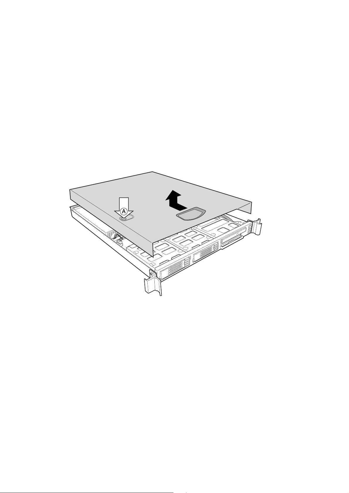
Removing the Cover
1. While depressing the tw o but tons (A) on top of the co ver, slide the cover to the rear until
you can lift it from the chassis.
2. Set the cover aside and away from the immediate work area.
20
Figure 6. Removing the Cover
Assembling the System
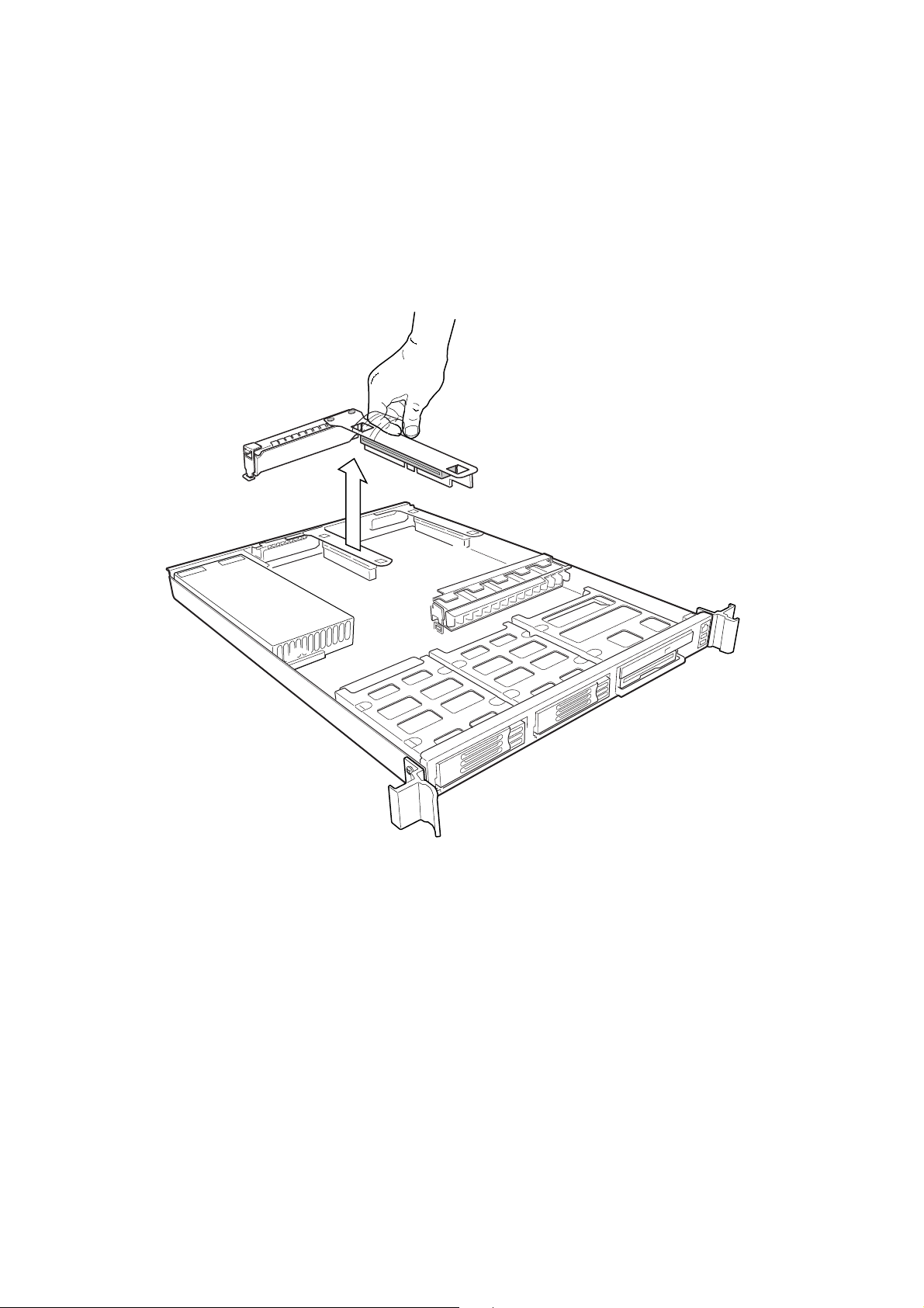
Removing the Riser Cards
1. Insert your finger in the plastic loop.
2. Pull straight up and remove the riser card from the chassis.
3. Remove the other riser card in the same manner.
Figure 7. Removing a Riser Card
MAXDATA PLATINUM Server Case User’s Manual
21

Removing the Fan Module
At the the left end of the module, press at (A) to release tab (B) from chassis slot (C) and lift
up until the module releases from the chassis.
Figure 8. Removing the Fan Module
22
Assembling the System

Removing the Power Supply
Grasp both ends of the power supply and lift it out of the chassis.
Figure 9. Removing the Power Supply
MAXDATA PLATINUM Server Case User’s Manual
23

Removing the Drive Carriers
1. Pull the retention lever (A) toward you until the tab end (B) of the lever is free of the
housing slot (C).
2. Pull the drive carrier forward and out of the drive bay.
Figure 10. Removing a Drive Carrier from a Drive Bay
24
Assembling the System

Installing System Components
CAUTION
System components must be installed in the order presented below. If in stalled in a diff erent order, component damage may occur.
Installing the Server Board
1. Ensure that the edge of the insulator sheet is below the studs in the rear chassis
wall and that the sheet is laying flat on the chassis floor.
2. Remove the server board from its packaging and antistatic bag.
3. While placing the board on the chassis standoffs, carefully position the board I/O
connectors in the rear chassis I/O openings.
4. Adjust board position so that its three mounting holes rest securely on the three
shouldered standoffs
✏
NOTE
The three holes used to mount the server board to the standoffs have white circles around
them.
MAXDATA PLATINUM Server Case User’s Manual
25

5. Attach the board to the chassis using the three thumbscrews shipped in the chassis
accessory kit.
26
Figure 11. Mounting the SCB2 Server Board
Assembling the System

Installing the Power Distribution Board
1. Orient the board so that the white 24-pin power connector (C) is on the right and
facing toward the rear of the chassis.
2. Plug connector (C) in the white power connector on the server board and press
the two firmly together until they are fully seated.
✏
NOTE
Do not connect cable (A) and (B) at this time.
A. Backplane power connector (6-pin)
B. Auxiliary signal connector (4-pin)
C. White power connector (24-pin)
Figure 12. Installing the Power Distribution Board
MAXDATA PLATINUM Server Case User’s Manual
27

Installing the Backplane Board
1. Place the backplane board on the chassis standoffs (A) so that each of the
seven mounting holes fit over a standoff.
Figure 13. Installing the Backplane Board
2. While gently pushing the board down, slide it to the left (B) until it snaps in place.
3. Install the thumbscrew (C) that secures the board to the chassis.
4. Insert the 6-pin connector from the power distribution board in the backplane
power connector (D).
5. If the backplane board is SCSI, set the SCSI cable aside for installation later.
28
Assembling the System

Installing the Power Supply Module
1. Place the edge connector end of the power supply on the chassis floor and slide it
towards the front of the chassis (A) until the edge connector is fully inserted in the
power distribution board connector.
2. Make sure that the rear of the power supply (B) is fully seated on the chassis floor and
in front of the raised guides (C).
Figure 14. Installing the Power Supply
MAXDATA PLATINUM Server Case User’s Manual
29

Installing the Fan Module
1. Position the fan module so that the power cable is positioned closest to the center of
the chassis.
2. Slide the “L” shaped foot on the right end of the fan module under the chassis tab.
3. Lower the module onto the chassis floor. Ensure it is situated between the raised
guides, not on top of them.
4. Press down on the left end of the module until tab (B) snaps into chassis slot (C).
5. Plug the power cable in the system fan connector (A) on the server board.
30
Figure 15. Installing the Fan Module
Assembling the System

Cable Routing
SCSI System Cable Routing
Figure 16. Cable Routing – SCSI System
1. At tach one end of the fle x circuit cable (C) to the floppy/front panel/IDE connector on the
server board. Route the cable to the backplane board and attach the opposite cable end
to the matching connector on the backplane.
2. On the SCSI ribbon cable (D), locate the end that is labeled baseboard. Connect that end
to the SCSI connector on the server board. Route the cable to the backplane board.
Place the cable under the cable clip and attach the cable connector to the connector on
the backplane board.
3. Route the auxiliary signal cable (B) from the power distribution board ov er the top of the
SCSI cable. Connect it to the 5-pin auxiliary signal connector on the server board.
4. Route the power cable (A) from the po w er distribution board to the bac kplane board and
insert it in the white 6-pin connector.
5. Connect the fan module cable (G) to the white 7 -pin fan module connector on the server
board.
6. Connect the front panel cable (F) to the front panel board. Insert the cable in the cable
clip (
7. Connect the USB cable (E) to the 10-pin USB connector on the ser ver board. Route
the cable next to the right end of the fan module and press it into the slot (
near the bottom of the module. Insert the cable in the cable clip (**), and plug the
cable into the USB connector on the front panel board.
), route it to the backplane, and attach it to the matching connector.
**
) located
*
MAXDATA PLATINUM Server Case User’s Manual
31

ATA System Cable Routing
Figure 17. Cable Routing – ATA System
1. Att ach one end of the flex circuit cable (C) to the floppy/front panel/IDE connector on
the server board. Route the cable to the backplane board and attach the opposite
cable end to the matching connector on the backplane.
CAUTION
After connection of cable (C) in step 1, ensure that each cable connector is properly seated
in the board connector. The connector should be parallel to its board connector and not
cocked to one side. If in doubt, remove, reinsert, and recheck.
32
Assembling the System

2. Connect one end of the shorter ATA-100 ribbon cable (D) to the secondary ATA-100
connector on the server board (the one closer to the front of the chassis). Route the
cable to the backplane board and connect the other end of the cable to the secondary
ATA-100 connector on the backplane. Connect one end of the longer ATA-100 ribbon
cable (D) to the primary ATA-1 00 connector on the server board. Route the primary AT A
cable over the top of the secondary ATA cable to the backplane board and connect the
other end to the primary ATA-100 connector on the backplane.
3. Route the auxiliary signal cable (B) from the power distribution board ov er the top of the
ATA-100 cables. Connect it to 5-pin auxiliary signal connector on the server board.
4. Route the power cable (A) from the po w er distribution board to the bac kplane board and
insert it into the white 6-pin connector.
5. Connect the fan module cable (G) to the white 7 -pin fan module connector on the server
board.
6. Connect the front panel cable (F) to the front panel board. Insert the cable in the cable
clip (
7. Connect the USB cable (E) to the USB connector on the front panel board. Insert the
cable into the cable clip (
8. Proceed to “Installing the Fan Module” on page 34 where you will complete the
routing and connection of the USB cable.
), route it to the backplane, and attach it to the matching connector.
**
) located on the chassis floor.
**
MAXDATA PLATINUM Server Case User’s Manual
33

Installing the Fan Module
1. Position the fan module so that the power cable is located closest to the center of the
chassis.
2. Insert the USB cable in slot (A) located on the chassis sidewall end of the module.
3. Slide the “L” shaped foot on the chassis sidewall end of the fan module under the
chassis tab.
4. Lower the module onto the chassis floor. Ensure that it is situated between the raised
guides, not on top of them.
5. Press down on the left end of the module until tab (B) snaps into chassis slot (C).
6. Plug the power cable in the system fan connector (G of Figure 16 or Figure 17) on the
server board.
7. Plug the USB cable into to the 10-pin USB connector on the server board
(E of Figure 16 or Figure 17).
34
Figure 18. Installing the Fan Module
Assembling the System

Installing the Air Baffle
1. Ensure the flex cable, aux power cable, and SCSI or ATA (depending on board type)
cables are routed under where you will be installing the air baffle.
2. Aligning pin (A) with the board mounting hole, position the air baffle over the white
server board power connector.
3. Lower the baffle into position and press it down against the chassis floor.
4. Ensure tabs (B) and (C) are under the edge of the server board.
Figure 19. Installing the Air Baffle
MAXDATA PLATINUM Server Case User’s Manual
35

Installing the Power Cord and Strain Relief Strap
NOTE
✏
If you will be placing your server in a rack, wait to install the power cord until after the
server is in the rack.
1. Insert the expansion nipple (A) of the strain relief strap into the chassis hole.
2. Plug the power cord into the power supply but not into the power source.
3. Insert the power cord into the plastic loop (B) of the strain relief.
4. Pull the plastic band (C) until it tightens around the power cord.
To release the plastic loop and free the cord, squeeze the release lever (D).
Figure 20. Installing the Power Cord and Strain Relief Strap
Adding Components to the Server Board
After installing the server board, you must add the desired number of processors and memory
DIMMs. For instructions, see the Intel Ser ver Board SBC2 Quick Start Guide that shipped
with your server board.
✏ NOTE
Once the server board and its components are installed, you are done assembling the system
unless you hav e optional peripherals or add-in cards you wish to install. If you need to install
these components, continue on to the next section. Otherwise, install the cover and bezel
and continue on to Chapter 4, which describes how to install the system in a cabinet.
36
Assembling the System

Installing Optional Peripherals
Peripherals and add-in cards are not included in y our system and must be purc hased separately.
The following sections describe how to install various peripherals.
Installing a PCI Card on a Riser Card
The riser card nearest the sidew all of the c hassis supports a single Lo w Profile (LP) PCI addin card. The riser card at the centerline of the chassis supports a single full-length, fullheight add-in card or an LP card. If an LP card is installed in the standard full-height riser
card, it must be equipped with a standard full-height PCI mounting bracket.
✏ NOTE
Add-in cards must be installed to a riser card while the riser card is removed from the c hassis.
1. Open the retainer clip (A) and remove the filler panel from the rear retention brac ket (B)
of the riser card.
2. Insert the PCI card edge connector in the riser PCI slot (D) while aligning the end
of the PCI card bracket in opening (C).
3. Firmly push the PCI card connector into the riser card slot until it is fully seated.
4. Close the retainer clip (A). Ensure the clip is latched.
Figure 21. Installing a PCI Card in a Riser Card
MAXDATA PLATINUM Server Case User’s Manual
37

Installing a Riser Card on the Server Board
1. Insert the riser card connector into the server board slot while aligning the tabs on the
rear retention bracket with the holes in the chassis.
CAUTION
Press the riser card straight down into the slot. Tipping it in the slot while installing it may
damage the riser card or slot.
2. Firmly press the riser card straight down until it is fully seated in the server board slot.
38
Figure 22. Installing a Riser Card on the Server Board
Assembling the System

Installing a Hard Drive
A SCSI system can support two hot swappable hard driv es in the drive ba ys, plus one in the
flex bay. An ATA system can support two non-hot swappable hard drives in the drive bays.
CAUTION
Not all ATA hard drives are supported by this server. Unsupported drives will mechanically
not mate with the connector in the drive bay. To see a list of validated manufacturers and
hard drive types, go to:
http://support.intel.com/support/motherboards/server
CAUTION
To allow proper airflow and server cooling, all drive bays must contain either a carrier with a
hard drive installed or a carrier with an air baffle installed.
1. If the drive carrier is installed in the drive bay, remove it.
2. Remove the air baffle (Figure 23, A) from the drive carrier by removing the four
screws (B) from the slide track (C).
3. Store the air baffle for future reinstallation in the event you must operate your
server without a drive in one of the bays.
Figure 23. Removing an Air Baffle from a Drive Carrier
MAXDATA PLATINUM Server Case User’s Manual
39

4. Remove the hard drive from its wrapper and place it on an anti-static surface.
5. Set any jumpers and/or switches on the drive according to the drive manufacturer’s
instructions.
6. With the drive circuit-side-down (Figure 24, A), position the connector end (E) so that it is
facing the back of the carrier (B).
7. Align the holes in the drive to the holes in the drive carrier slide track (C), insert the
screws (D) that you previously removed, and attach the carrier to the drive.
Figure 24. Attaching a Drive to a Carrier
8. Slide the carrier/drive all the way into the drive bay with the retention lever in the fully
open position.
9. Push the retention lever closed to secure the carrier/drive in the bay.
10. Reinstall a carrier/air baffle in any bays where you are not installing a carrier/drive.
40
Assembling the System

Installing a CD-ROM Drive/FDD Module
Your server does not come with a CD-ROM drive or floppy disk driv e. As an accessory , Intel
offers a slim-line CD-ROM drive/FDD module that you may purchase and install in the flex
bay.
1. Remove the filler panel and plug from the front of the chassis.
2. Slide the module into the flex bay until you feel the connectors touch.
3. Push the module in about 3/16 of an inch (5 mm) more to fully engage the connectors.
4. Push the handle bar down (A).
5. If you have finished your work in the peripheral bays, install the bezel.
®
Figure 25. Installing a CD-ROM Drive/FDD Module
MAXDATA PLATINUM Server Case User’s Manual
41

Installing a Bezel
Place the bezel between the c hassis handles and push it toward the front of the c hassis until
it snaps into place.
Figure 26. Installing the Bezel
42
Assembling the System

3 Installing the System in a Rack
Equipment Rack Precautions
CAUTION
ANCHOR THE EQUIPMENT RACK: The equipment rac k must be anc hored to an unmovable
support to prevent it from f alling over when one or more servers are extended in front of it
on slide assemblies. The equipment rac k must be installed according to the manuf acturer’s
instructions. You must also consider the weight of any other device installed in the rack.
MAIN AC POWER DISCONNECT: Y ou are responsible for installing an AC po wer disconnect
for the entire rack unit. This main disconnect must be readily accessible, and it must be
labeled as controlling power to the entire unit, not just to the server(s).
GROUNDING THE RACK INST ALLA TION: T o avoid the potential for an electrical shoc k hazard,
you must include a third wire saf ety grounding conductor with the rack installation. If server
power cords are plugged into AC outlets that are part of the rack, then you must provide
proper grounding for the rack itself. If server power cords are plugged into wall AC outlets,
the safety grounding conductor in each power cord provides proper grounding only for the
server. Y ou must provide additional, proper grounding f or the rac k and other devices installed
in it.
OVER CURRENT PROTECTION: The server is designed for an AC line voltage source with
up to 20 amperes of over current protection. If the po wer system for the equipment rack is
installed on a branch circuit with more than 20 amperes of protection, you must provide
supplemental protection for the server. If more than one server is installed in the rack, the
power source for each server must be from a separate branch circuit.
CAUTION
Temperature: The operating temperature of the ser ver, when installed in an equipment
rack, must not go below 5 °C (41 °F) or rise above 35 °C (95 °F). Extreme fluctuations in
temperature can cause a variety of problems in your server.
MAXDATA PLATINUM Server Case User’s Manual
43

Ventilation: T he equipment rac k must provide suf ficient airflo w to the front of the server to
maintain proper cooling. It must also include ventilation sufficient to exhaust a maximum of
1200 Btu’s per hour for a fully loaded server.
It is important to note that this is the maximum, and a minimum or typical system could be
much less. You may want to calculate the BTU/hr more accurately for y our configuration. An
extra 500 BTU/hr over many systems would translate into a large error calculating air
conditioning capacity.
44
Installing the System in a Rack

4 Working Inside Your Server
This c hapter describes how to replace components in your server af ter it has been set up. All
references to lef t, right, front and rear are based on the reader facing the front of the c hassis.
Tools and Supplies Needed
Antistatic wrist strap (recommended)
Safety: Before You Remove the Cover
Before remo ving the system cover to work inside the sy stem, observe these safety guidelines:
1. Turn off all peripheral devices connected to the system.
2. Turn off the system by pressing the power button on the front of the system.
Then unplug the AC power cord from the system or wall outlet.
3. Label and disconnect all peripheral cables and all telecommunication lines connected
to I/O connectors or ports on the back of the system.
4. Attach a wrist strap to a chassis ground of the system – any unpainted metal surface –
before handling components.
Warnings and Cautions
These warnings and cautions apply whenev er you remo ve the chassis cover to access components inside the server. Only a tec hnically qualified person should integrate and configure
the server.
Lithium Battery Replacement
CAUTION
Refer to technically qualified persons only for replacement of battery.
The following w arning is pro vided on the server board configuration label, whic h is pro vided
with the Intel
place this label. T herefore, the label must be placed permanently on the inside of the c hassis,
as close to the battery as possible.
WARNING
®
server board boxed product. There is insufficient space on the server board to
Danger of explosion if bat tery is incorrectly replaced. Replace with only the same or equivalent type recommended by the manufacturer. Dispose of used batteries according to the
manufacturer’s instructions.
MAXDATA PLATINUM Server Case User’s Manual
45

ADVARSEL!
Lithiumbatteri - Eksplosionsf are ved f ejlagtig håndtering. Udskiftning må kun ske med bat teri
af samme fabrikat og type. Levér det brugte batteri tilbage til leverandøren.
ADVARSEL!
Lithiumbatteri - Eksplosjonsf are. V ed utskif ting benyt tes kun bat teri som anbefalt av apparatfabrikanten. Brukt batteri returneres apparatleverandøren.
VARNING
Explosionsfara vid f elaktigt batterib yte. Använd samma bat terityp eller en ekvivalent typ som
rekommenderas av apparat tillverkaren. Kassera an vänt batteri enligt f abrikantens instruktion.
V AROITUS
Paristo voi räjähtää, jos se on virheellisesti asennet tu. V aihda paristo ainoastaan laitevalmistajan
suosittelemaan tyyppiin. Hävitä käytetty paristo valmistajan ohjeiden mukaisesti.
46
Working inside your Server

Air Baffle
The air baffle must be removed before you can replace any of the following components:
fan module, power distribution board, backplane board, and server board.
Removal
1. Before removing the cover to work inside the system, observe the safety guidelines on
page 45.
2. Remove the chassis cover.
3. Gently spread the air baffle walls at (B) and (C) and lift up until pin (A) is free of the board
mounting hole. Remove the baffle from of the chassis.
Installation
1. Ensure the flex cable, aux power cable, and SCSI or ATA (depending on board type)
cables are routed under where you will be installing the air baffle.
2. Aligning pin (A) with the board mounting hole, position the air baffle over the white
server board power connector.
3. Lower the baffle into position and press it down against the chassis floor.
4. Ensure tabs (B) and (C) are under the edge of the server board.
Figure 27. Removing the Air Baffle
MAXDATA PLATINUM Server Case User’s Manual
47

Replacing a Hard Drive
CAUTION
Not all ATA hard drives are supported by this server. Unsupported drives will not
mate mechanically with the connector on the inside of the driv e bay. To see a list of validated
manufacturers and hard drive types, go to:
http://support.intel.com/support/motherboards/server
CAUTION
A TA hard drives are NO T hot swappable. SCSI hard driv es are hot swappable. The two types
are not interchangeable. In a SCSI sy stem, the hard drive in the flex ba y can be hot swapped.
The badge on your server’s bezel identifies the type of system you have.
CAUTION
To allow proper airflow and cooling during operation, all drive bays must contain either a
carrier/drive or a carrier with air baffle installed.
1. Before removing the cover to work inside the system, observe the safety guidelines
on page 45.
2. Remove the bezel from the front of the chassis.
3. Pull the retention lever (A) toward you until the tab end (B) of the lever is free of the
housing slot (C).
4. Pull the carrier/drive forward and out of the drive bay.
Figure 28. Removing a Carrier and Hard Drive from a Drive Bay
48
Working inside your Server

5. Remove the hard drive from the carrier (A) by removing the four screws (D) from
the slide track (C). Lift the drive out of the carrier (B).
6. Remove the new hard drive from its wrapper and place it on an anti-static surface
7. Set any jumpers and/or switches on the drive according to the drive manufacturer’s
instructions.
Figure 29. Removing a Hard Drive from a Carrier
8. Install the new drive in the carrier and the carrier/drive into the drive bay
(see steps 5 through 8 of “Installing a Hard Drive” on page 39).
9. Reinstall a carrier/air baffle in any bays where you are not reinstalling a carrier/drive.
MAXDATA PLATINUM Server Case User’s Manual
49

Replacing a CD-ROM Drive/FDD Module
CAUTION
A CD-ROM drive/FDD module is NO T hot sw appable. Before replacing it, y ou must first take
the server out of service, turn off all peripheral devices connected to the sy stem, turn of f the
system by pressing the power button, and unplug the AC power cord from the system or
wall outlet.
1. Before removing the cover to work inside the system, observe the safety guidelines
on page 45.
2. Remove the bezel from the front of the chassis.
3. Rotate the module’s handle bar up (A) and pull the module out of the flex bay.
4. Slide a new module into the flex bay until you feel the connectors touch.
5. Push the module in about 3/16 of an inch (5 mm) more to fully engage the connectors.
6. Rotate the handle bar down.
7. Reinstall the bezel.
Figure 30. Removing a CD-ROM Drive/FDD Module
Replacing a PCI Add-in Card
✏ NOTE
Add-in cards must be replaced while the riser card is removed from the chassis.
1. Before removing the co ver to work inside the system, observe the safety guidelines on
page 45.
2. Remove the chassis cover.
3. Insert your finger in the plastic loop (A).
4. Pull straight up and remove the riser card assembly from the chassis.
50
Working inside your Server

5. Open the retainer clip (B) on the riser card retention bracket.
6. Pull the PCI card out of the riser card slot (C).
7. Install the new PCI add-in card on the riser.
8. Insert the riser card connector in the server board slot while aligning the tabs on the rear
retention bracket with the holes in the chassis.
CAUTION
Press the riser card straight down into the slot. Tipping it in the slot while installing it may
damage the riser card or board slot.
9. Firmly press the riser card straight down until it is seated in the server board slot.
10. Replace the chassis cover if you have no additional work to do inside the chassis.
Figure 31. Removing a Riser Card
MAXDATA PLATINUM Server Case User’s Manual
51

Replacing the Power Supply Module
CAUTION
Your server does not have a redundant power supply. Before replacing the power supply
you must take the server out of service.
1. Before removing the co ver to work inside the system, observe the safety guidelines on
page 45.
2. Unplug the power cord from the power source and the power supply module.
3. Remove the chassis cover.
CAUTION
Lift the rear of the module up only enough to clear the raised guides. Lifting higher may
damage the edge connector and power distribution board.
4. Lift the rear of the module up (A) only enough to clear the raised guides (C) on the
chassis floor.
5. Push the module to the rear of the chassis (B) until it disengages from the power
distribution board.
6. Lift the module out of the chassis.
7. Place the edge connector end of the replacement module onto the chassis floor
and slide it toward the front of the c hassis until the edge connector is fully inserted in the
power distribution board connector.
8. Make sure that the rear of the power supply is fully seated on the chassis floor
and in front of the raised guides (C).
9. Replace the chassis cover.
52
Figure 32. Removing the Power Supply Module
Working inside your Server

Replacing the Fan Module
1. Before removing the cover to work inside the system, observe the safety guidelines on
page 45.
2. Remove the cover from the chassis.
3. Remove the air baffle.
4. Unplug the fan cable from the server board (D).
5. At the left end of the module, press on tab (B) to release it from chassis slot (C).
6. Lift the module from the chassis. When the right end is free, detach the USB cable.
7. Attach the USB cable to the replacement module.
8. Slide the “L” shaped foot on the right end of the module under the chassis tab near the
chassis sidewall.
9. Lower the module to the chassis floor. Ensure it is sit uated between the raised guides,
not on top of them.
10. Press down on the left end of the module until tab (B) fits into chassis slot (C).
11. Plug the power cable into the system fan connector on the server board.
12. Install the air baffle.
13. Replace the chassis cover.
Figure 33. Replacing the Fan Module
MAXDATA PLATINUM Server Case User’s Manual
53

Replacing a Backplane Board
1. Before removing the co ver to work inside the system, observe the safety guidelines on
page 45.
2. Remove the cover from the chassis.
3. Remove all drives from the drive bays and flex bay.
4. Remove the air baffle.
5. Unplug all cables connected to the backplane board.
6. Remove and save the thumbscrew (A) that secures the board to the chassis.
7. Slide the board to the right (B) until it disengages from the standoffs (C) and lift it
out of the chassis.
8. Place the new backplane board on the chassis standoffs so that each mounting
hole fits over a standoff.
Figure 34. Replacing the Backplane Board
9. While gently pushing the board down, slide the board to the lef t until it snaps into place.
10. Install the thumbscrew that secures the board to the chassis.
11. Plug in all cables removed from the backplane board.
12. Install the air baffle.
13. Install all drives removed earlier.
14. Replace the chassis cover.
54
Working inside your Server

Replacing a Power Distribution Board
1. Before removing the cover to work inside the system, observe the safety guidelines on
page 45.
2. Remove all drives from the drive bays and flex bay.
3. Remove the cover from the chassis.
4. Remove the power supply module.
5. Remove the air baffle.
6. Unplug auxiliary signal connector (B) from the server board.
7. Remove the SCSI cable on a SCSI system or the two AT A-100 cables on an A TA system.
8. Unplug power connector (A) from the bac kplane board and remov e the backplane board.
9. Unplug the power distribution board (C) from the server board and remove it from the
chassis.
Figure 35. Replacing the Power Distribution Board
10. Install the replacement board by plugging its white 24-pin power connector into
the server board power connector . Press the two firmly together until the y are fully seated.
11. Install the backplane board and plug in cabling.
12. Route and connect all other cabling removed earlier.
13. Install the air baffle.
14. Install the power supply module.
15. Replace the chassis cover.
16. Install any drives removed earlier.
MAXDATA PLATINUM Server Case User’s Manual
55

Replacing a Front Panel Board
1. Before removing the co ver to work inside the system, observe the safety guidelines on
page 45.
2. Remove the cover from the chassis.
3. Unplug the USB and backplane cables from the front panel board (A).
Figure 36. Replacing the Front Panel Board
4. Remove the thumbscrew (B) from the board.
5. Remove the front panel board from the chassis (C).
6. Install the new board in the chassis being careful to insert the LED light pipes into the
front panel holes.
7. Secure the board to the chassis with the thumbscrew.
8. Plug the USB and backplane cables back into the front panel board.
9. Replace the chassis cover.
56
Working inside your Server

Replacing a Server Board
1. Before removing the cover to work inside the system, observe the safety guidelines
on page 45.
2. Remove the cover from the chassis.
3. Remove both riser card/PCI card assemblies.
4. Remove the power supply module.
5. Remove the air baffle.
6. Disconnect the USB cable from the server board.
7. At the backplane board, disconnect the ribbon cable that comes from the front panel
board.
8. Remove the fan module.
9. Disconnect both ends of all remaining cables.
10. Remove the backplane board.
11. Remove the power distribution board.
12. Remove any processors, terminators, and memory cards that you wish to use with the
new board.
13. Remove the three mounting screws that secure the server board to the chassis
(see Figure 37).
Figure 37. Removing the Server Board
14. Slide the board toward the front of the chassis until the I/O connectors are clear of the
chassis I/O openings. Place the server board in an anti-static bag.
15. If you are installing a SCSI server board, remov e the SCSI knock out at the I/O ports at the
back of the chassis.
16. Ensure that the Mylar insulator sheet is seated securely over the standoffs, is laying flat
on the chassis floor, and that the edge of the sheet is seated below the st uds in the rear
chassis wall.
MAXDATA PLATINUM Server Case User’s Manual
57

17. Remove the replacement server board from its packaging and antistatic bag.
18. While placing the board on the chassis standoffs, carefully position the board I/O
connectors in the rear chassis I/O openings.
✏ NOTE
The SCB2 uses three holes to mount the board to the chassis stand-offs. Each hole is
designated with a white circle around them.
19. Adjust board position so that the two mounting holes near the board edges rest securely
on the two-shouldered standoffs.
20. Install the power distribution board.
21. Install the backplane board.
22. Install the fan module.
23. Cable the new server board to the other system components.
24. Install the air baffle.
25. Install the power supply module.
26. Inst all the processor(s), terminator, and memory cards that you wish to use with the
new board.
27. Install both riser card/PCI card assemblies.
28. Replace the chassis cover if you have no additional work to do inside the chassis.
58
Working inside your Server

Appendix A
Regulatory and Certification Information
WARNING
You must adhere to the assembly instructions in this guide to ensure and maintain
compliance with existing product certifications and appr ov als. Use only the descr ibed,
regulated components specified in this guide. Use of other products / components
will void the UL Listing and other regulatory approvals of the product, and will most
likely result in noncompliance with product regulations in the region(s) in which the
product is sold.
Product Regulatory Compliance
This Server Chassis subassembly, when correctly integrated per this guide, complies with
the following safety and electromagnetic compatibility (EMC) regulations.
Product Safety Compliance
• UL 1950 - CSA 950 (US/Canada)
• EN 60 950 (European Union)
• IEC60 950 (International)
• CE – Low Voltage Directive (73/23/EEC) (European Union)
• EMKO-TSE (74-SEC) 207/94 (Nordics)
Product EMC Compliance
• FCC /ICES-003, Class A Emissions (USA/Canada) Verification
• CISPR 22, 3
• EN55022, Class A Emissions (CENELEC Europe)
• EN55024: 1998, Immunity (CENELEC Europe)
• EN61000-3-2, Harmonics (CENELEC Europe)
• EN61000-3-3, Voltage Flicker (CENELEC Europe)
• CE – EMC Directive 89/336/EEC (CENELEC Europe)
rd
Edition, Class A Emissions (International)
Product Regulatory Compliance Markings
This product is provided with the following Product Regulation Markings:
• cULus Mark (USA/Canada)
• CE Mark (CENELEC Europe)
• GS Mark (Germany)
• FCC, Class A Markings (USA)
• ICES-003, Class Markings (Canada)
MAXDATA PLATINUM Server Case User’s Manual
59

Electromagnetic Compatibility Notices
FCC Verification Statement (USA)
This device complies with Part 15 of the FCC Rules. Operation is subject to the following
two conditions: (1) This device ma y not cause harmful interf erence, and (2) this device must
accept any interference receiv ed, including interf erence that may cause undesired operation.
MAXDATA Computer GmbH & Co. KG
Elbestraße 16
D - 45768 Marl, Germany
www.maxdata.com
This equipment has been tested and found to comply with the limits for a Class A digital
device, pursuant to Part 15 of the FCC Rules. These limits are designed to provide reasonable protection against harmful interference in a residential installation. This equipment
generates, uses, and can radiate radio frequency energy and, if not installed and used in
accordance with the instructions, may cause harmful interf erence to radio communications.
However, there is no guarantee that interference will not occur in a particular installation. If
this equipment does cause harmful interference to radio or television reception, which can
be determined by turning the equipment off and on, the user is encouraged to try to correct
the interference by one or more of the following measures:
Reorient or relocate the receiving antenna.
Increase the separation between the equipment and the receiver.
Connect the equipment into an outlet on a circuit different from that to which the
receiver is connected.
Consult the dealer or an experienced radio/TV technician for help.
Any changes or modifications not expressly approved by the grantee of this device could
void the user’ s authority to operate the equipment. The customer is responsible f or ensuring
compliance of the modified product.
Only peripherals (computer input/output devices, terminals, printers, etc.) that comply with
FCC Class A or B limits may be attached to this computer product. Operation with noncompliant peripherals is likely to result in interference to radio and TV reception.
All cables used to connect to peripherals must be shielded and grounded. Operation with
cables, connected to peripherals that are not shielded and grounded may result in interference to radio and TV reception.
ICES-003 (Canada)
Cet appareil numérique respecte les limites bruits radioélectriques applicables aux appareils
numériques de Classe Aprescrites dans la norme sur le matériel brouilleur: “Appareils
Numériques”, NMB-003 édictée par le Ministre Canadian des Communications.
(English translation of the notice above.) This digital apparatus does not exceed the Class A
limits for radio noise emissions from digital apparatus set out in the interference-causing
equipment standard entitled “Digital Apparatus,” ICES-003 of the Canadian Department of
Communications.
60
Technical reference

Europe (CE Declaration of Conformity)
This product has been tested in accordance too, and complies with the Low Voltage Directive (73/23/EEC) and EMC Directive (89/336/EEC). The product has been marked with the CE
Mark to illustrate its compliance.
Regulated Specified Components
To maintain the UL listing and compliance to other regulatory certifications and/or declarations, the following regulated components must be used, and conditions adhered to.
Interchanging or use of other component will v oid the UL Listing and other product certifications and approvals.
Updated product information for configurations can be found on the Intel
Web-site at:
http://channel.intel.com/go/serverbuilder
®
Server Builder
If you do not have access to Intel’s web address please contact your local Intel
®
representa-
tive.
• SR1200 chassis (base chassis is provided with power supply and fans)
• Server board
• Add-in boards
– you must use an Intel
– must have a printed wiring board flammability rating of minimum UL94V-
®
Server Board – UL Recognized.
– UL listed.
1. Add-in boards containing e xternal po w er connectors and/or lithium batteries must be
UL Recognized or UL Listed. Any add-in board containing modem telecommunication
circuitry must be UL Listed. In addition the modem must have the appropriate
telecommunications, safety and EMC approvals for the region in which it is sold.
• Peripheral storage devices
– must be UL Recognized or UL listed accessory and TUV
or VDE licensed. Maximum power rating of any one device is 19W. Total server
configuration is not to exceed maximum loading conditions of power supply.
When using a UL Recognized Peripheral Storage Device, the plastic bezel must be made of
a UL recognized plastic with flammability rating of UL94V-1.
MAXDATA PLATINUM Server Case User’s Manual
61

62
Warning

B Safety Warnings
WARNUNG: Deutsch
WARNING: English (US)
AVERTISSEMENT : Français
MAXDATA PLATINUM Server Case User’s Manual
63

WARNHINWEISE: Deutsch
Benutzer können am Netzgerät dieses Produkts keine Reparaturen vornehmen.
Das Produkt enthält möglicher weise mehrere Netzgeräte. Wartungsarbeiten müssen
von qualifizierten Technikern ausgeführt werden.
V ersuc hen Sie nicht, das mitgelieferte Netzkabel zu ändern oder zu verwenden, wenn es
sich nic ht genau um den erf orderlic hen Typ handelt. Ein Produkt mitmehrere Netzgeräten
hat für jedes Netzgerät ein eigenes Netzkabel.
Der Netzschalter auf der Vorderseite trennt den Server nicht von der Versorgungsspannung. Um den Server spannungsfrei zu bekommen, müssen Sie den Stecker des
Kaltgerätekabels aus der Steckdose oder aus dem Netzteil ziehen.
SICHERHEITSMASSNAHMEN: Immer wenn Sie die Gehäuseabdeckung abnehmen,
um an das Systeminnere zu gelangen, sollten Sie folgende Schritte beachten:
1. Schalten Sie alle an Ihr System angeschlossenen Peripheriegeräte aus.
2. Schalten Sie das System mit dem Hauptschalter aus.
3. Ziehen Sie den Stecker des Kaltgerätekabels aus der Steckdose oder aus dem Netz
teil.
4. Beschriften Sie alle Anschlusskabel der I/O Anschlüsse oder Ports auf der Rückseite
des Systems und ziehen Sie die Kabel ab.
5. Tragen Sie ein geerdetes, antistatisches Armband, um elektrostatische Entladungen
zuvermeiden.
6. Schalten Sie das System niemals ohne ordnungsgemäß montiertes Gehäuse ein.
Nachdem Sie die oben erwähnten ersten sechs SICHERHEI TSMA SSNAHMEN durc hgeführt haben, können Sie die Abdeckung auf die folgende Art abnehmen:
1. Öffnen und entfernen Sie die Verschlusseinrichtung (Vorhängeschloss) auf der Rückseite des Systems, falls eine solche Verschlusseinrichtung montiert ist.
2. Entfernen Sie alle Schrauben der Gehäuseabdeckung.
3. Nehmen Sie die Abdeckung ab.
Zur ordnungsgemäßen Kühlung und Lüftung muss die Gehäuseabdeckung immer wie
der vor dem Einschalten montiert werden. Ein Betrieb des Systems ohne angebrachte
Abdeckung kann Ihr System oder Teile davon beschädigen. Um die Abdeckung wieder
anzubringen:
1. Vergewissern Sie sich, dass Sie keine Werkzeuge oder Teile im Innern des Systems
zurückgelassen haben.
2. Überprüfen Sie alle Kabel, Zusatzkarten und andere Komponenten auf ordnungsgemäßen Sitz und Montage.
3. Befestigen Sie die Abdeckung wieder am Gehäuse, indem Sie die zuvorgelösten
Schrauben wieder anbringen. Ziehen Sie diese gut an.
4. Bringen Sie die Verschlusseinrichtung (Vorhängeschloss) wieder an und schließen
Sie diese, um ein unerlaubtes Öffnen des Systems zu verhindern.
5. Schließen Sie alle externen Kabel und das Kaltgerätekabel Ihres Systems wieder an.
64
Warning

WARNUNG: Deutsch (Fortsetzung)
Der Mikroprozessor und der Kühler sind möglicherweise erhitzt, wenn das System in
Betrieb ist. Außerdem können einige Platinen und Gehäuseteile spitz e Ec ken und sc harf e
Kanten aufweisen. Arbeiten an Platinen und Gehäuse sollten vorsichtig ausgeführt werden. Sie sollten Schutzhandschuhe tragen.
Bei falschem Einsetzen einer neuen Batterie besteht Explosionsgefahr. Die Batterie darf
nur durch den selben oder einen entsprechenden, vom Hersteller empfohlenen Bat terietyp ersetzt werden. Entsorgen Sie verbrauchte Batterien entsprechend den Anweisungen des Herstellers bzw. gemäß der gesetzlichen Vorschriften Ihres Landes.
Das System wurde für den Betrieb in einer normalen Büroumgebung entwickelt. Der
Standort sollte:
• sauber und staubfrei sein (Hausstaub ausgenommen);
• gut gelüftet und keinen Heizquellen ausgesetzt sein (einschließlich direkter Sonnen-
einstrahlung);
• keinen Erschütterungen ausgesetzt sein;
• keine starken, von elektrischen Geräten erzeugte, elektromagnetische Felder auf-
weisen;
• in Regionen, in denen elektrische Stürme auftreten, mit einem Überspannungs-
schutzgerät verbunden sein; während eines elektrisches Sturms sollte keine Verbindung der Telekommunikationsleitungen mit dem Modem bestehen;
• mit einer geerdeten Wechselstromsteckdose ausgerüstet sein;
• über ausreic hend Platz v erfügen, um Zugang zu den Netzkabeln zugewährleisten, da
der Stromanschluss des Produkts hauptsächlich über die Kabel unterbrochen wird.
MAXDATA PLATINUM Server Case User’s Manual
65

W ARNING: English (US)
The power supply in this product contains no user-serviceable parts. There ma y be more
than one supply in this product. Refer servicing only to qualified personnel.
Do not attempt to modify or use the supplied AC power cord if it is not the exact type
required. A product with more than one pow er supply will have a separate A C pow er cord
for each supply.
The power button on the system does not turn off system AC power. To remove AC
power from the system, you must unplug each AC power cord from the wall outlet or
power supply.
The power cord(s) is considered the disconnect device to the mains (AC) power. The
socketoutlet that the system plugs into shall be installed near the equipment and shall
be easily accessible.
SAFETY STEPS: Whenever you remove the chassis covers to access the inside of the
system, follow these steps:
1. Turn off all peripheral devices connected to the system.
2. Turn off the system by pressing the power button.
3. Unplug all AC power cords from the system or from wall outlets.
4. Label and disconnect all cables connected to I/O connectors or ports on the back of
the system.
5. Provide some electrostatic discharge (ESD) protection by wearing an antistatic wrist
strap attached to chassis ground of the system-any unpainted metal surface when
handling components.
6. Do not operate the system with the chassis covers removed.
After you have completed the six SAFETY steps above, you can remove the system
covers. To do this:
1. Unlock and remove the padlock from the back of the system if a padlock has been
installed.
2. Remove and save all screws from the covers.
3. Remove the covers.
For proper cooling and airflow, always reinstall the chassis covers before turning on the
system. Operating the system without the covers in place can damage system parts.
To install the covers:
1. Check first to make sure you have not left loose tools or parts inside the system.
2. Check that cables, add-in boards, and other components are properly installed.
3. Attach the covers to the chassis with the screws removed earlier, and tighten them
firmly.
4. Insert and lock the padlock to the system to prevent unauthorized access inside the
system.
5. Connect all external cables and the AC power cord(s) to the system.
66
Warning

WARNING: English (continued)
A microprocessor and heat sink may be hot if the system has been running. Also, there
may be sharp pins and edges on some board and chassis parts. Contact should be made
with care. Consider wearing protective gloves.
Danger of explosion if the battery is incorrectly replaced. Replace only with the same
or equivalent type recommended by the equipment manufacturer. Dispose of used
batteries according to manufacturer’s instructions.
The system is designed to operate in a typical office environment. Choose a site that is:
• Clean and free of airborne particles (other than normal room dust).
• Well ventilated and away from sources of heat including direct sunlight.
• Away from sources of vibration or physical shock.
• Isolated from strong electromagnetic fields produced by electrical devices.
• In regions that are susceptible to electrical storms, we recommend you plug your
• Provided with a properly grounded wall outlet.
• Provided with sufficient space to access the power supply cords, because they
system into a surge suppresser and disconnect telecommunication lines to your
modem during an electrical storm.
serve as the product’s main power disconnect.
MAXDATA PLATINUM Server Case User’s Manual
67

A VER TISSEMENT : Fr ançais
Le bloc d’alimentation de ce produit ne contient aucune pièce pouvant être réparée par
l’utilisateur . Ce produit peut contenir plus d’un bloc d’alimentation. Veuillez contacter un
technicien qualifié en cas de problème.
Ne pas essayer d’utiliser ni modifier le cordon d’alimentation CA fourni, s ’il ne correspond
pas exactement au type requis. Le nombre de cordons d’alimentation CA fournis
correspond au nombre de blocs d’alimentation du produit.
Notez que le commutateur CC de mise sous tension /hors tension du panneau avant
n’éteint pas l’alimentation CA du système. Pour mettre le système hors tension, vous
devez débrancher chaque cordon d’alimentation de sa prise.
CONSIGNES DE SÉCURITÉ – Lorsque vous ouvrez le boîtier pour accéder à l’intérieur
du système, suivez les consignes suivantes :
1. Mettez hors tension tous les périphériques connectés au système.
2. Mettez le système hors tension en mettant l’interrupteur général en position OFF
(bouton-poussoir).
3. Débranchez tous les cordons d’alimentation c.a. du système et des prises murales.
4. Identifiez et débranchez tous les câbles reliés aux connecteurs d’E-S ou aux accès
derrière le système.
5. Pour prévenir les décharges électrostatiques lorsque vous touchez aux composants,
portez une bande antistatique pour poignet et reliez-la à la masse du système (toute
surface métallique non peinte du boîtier).
6. Ne faites pas fonctionner le système tandis que le boîtier est ouvert.
Une fois TOUTES les étapes précédentes accomplies, vous pouvez retirer les panneaux
du système. Procédez comme suit :
1. Si un cadenas a été installé sur à l’arrière du système, déverrouillez-le et retirez-le.
2. Retirez toutes les vis des panneaux et mettez-les dans un endroit sûr.
3. Retirez les panneaux.
Afin de permettre le refroidissement et l’aération du système, réinst allez toujours les
panneaux du boîtier avant de mettre le système sous tension. Le fonctionnement du
système en l’absence des panneaux risque d’endommager ses pièces. Pour installer les
panneaux, procédez comme suit :
1 . Assurez-vous de ne pas avoir oublié d’outils ou de pièces démontées dans le système.
2. Assurez-vous que les câbles, les cartes d’extension et les autres composants sont
bien installés.
3. Revissez solidement les panneaux du boîtier avec les vis retirées plus tôt.
4. Remet tez le cadenas en place et verrouillez-le afin de prév enir tout accès non autorisé
à l’intérieur du système.
5. Rebranchez tous les cordons d’alimentation c.a. et câbles externes au système.
68
Warning

A VERTISSEMENT : F rançais (suite)
Le microprocesseur et le dissipateur de chaleur peuvent être chauds si le système a été
sous tension. Faites également attention aux broches aiguës des cartes et aux bords
tranchants du capot. Nous vous recommandons l’usage de gants de protection.
Danger d’explosion si la batterie n ’est pas remontée correctement. R emplacer uniquement
par une batterie du même type ou d’un type équivalent recommandé par le fabricant.
Disposez des piles usées selon les instructions du fabricant.
Le système a été conçu pour fonctionner dans un cadre de tra vail normal. L’emplacement
choisi doit être :
• Propre et dépourvu de poussière en suspension (sauf la poussière normale).
• Bien aéré et loin des sources de chaleur, y compris du soleil direct.
• A l’abri des chocs et des sources de vibrations.
• Isolé de forts champs électromagnétiques générés par des appareils électriques.
• Dans les régions sujet tes aux orages magnétiques il est recomandé de branc her votre
système à un supresseur de surtension, et de débrancher toutes les lignes de
télécommunications de votre modem durant un orage.
• Muni d’une prise murale correctement mise à la terre.
• Suffisamment spacieux pour vous permettre d’accéder aux cordons d’alimentation
(ceux ci étant le seul moyen de mettre le système hors tension).
MAXDATA PLATINUM Server Case User’s Manual
69
 Loading...