

Page 1
Installation Guide for the
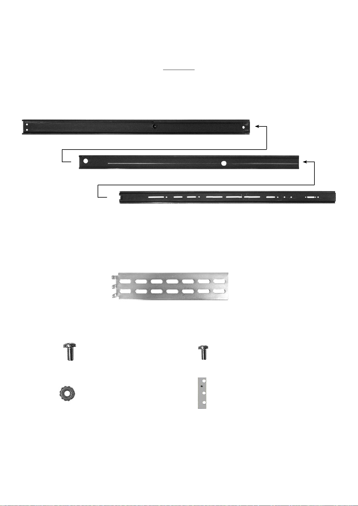
Parts List
The following is a list of all the parts that are relevant for installation; each part is designated
with a letter that is used in the installation guide.
The middle rail (B) is slid inside the external rail (A) and the internal rail (C) in turn is inside
the middle rail (B).
Note: Countersunk screws are not required.
Tip: Customers with a MAXDATA rack can simplify installation of the server by taking the
screws, washers, and clamping nuts from the fastening set of their cabinet.
External rail: A
Middle rail: B
Internal rail: C
End bracket: D
Round head screw,
large: E
Round head screw,
small: F
Nut: G Perforated plate
with threaded holes: H
Rack-Mount Slide Rail Kit from MAXDATA PLATINUM 200 and 500
Page 2

Installation
1. Pull the internal rail (C) out of the middle rail (B).
2. Leave the middle rail (B) inside the external rail (A).
3. Measure the distance between the front and rear breadboard section of your cabinet. Attach the silver end brackets (D) to the external rail (A) with two screws (E) and two nuts
(G) each. Be careful to make sure that the distance between the fastening bracket for the
external rail (A) and the end bracket (D) is the same as the distance between both breadboard sections of your server cabinet.
=
B
C
A
B
E
D
A
G
Page 3

4. Attach the rails in the rear of the server cabinet with the silver end brackets (D). First hold
the fastening bracket up to the breadboard. Then set the perforated plate with the threaded holes (H) behind the breadboard section. Finish by inserting the screws (E) from the
front through the breadboard and the fastening bracket to the perforated plates (H).
5. Attach the internal rails (C) with the locking device in the rear of the server housing with
the small screws (F).
6. When finished, you can slide the server into the server cabinet by pushing the inner rail (C)
into the middle rail (B). To be able to slide the server completely inside, you have to push
in the locking device at both sides of the rails.
Front: A
Rear: D
H
E
F
C B A
 Loading...