

MAXDATA Server PLATINUM 1600 IR – Quick Start Guide
BA DC
G EF
A
A
M
HL
D
I
N
P
O
F
J
H
C
B
E
K
G
O
N
J
KL
M
H
A
C
B
D
F
E
G
I
P
Q
EB C F GDA
EE
DD
CC
BB
AA
Z
Y
V
W
X
U
T
J
H
I
K
L
MNS R OPQ
Thank you for buying a MAXDATA PLATINUM
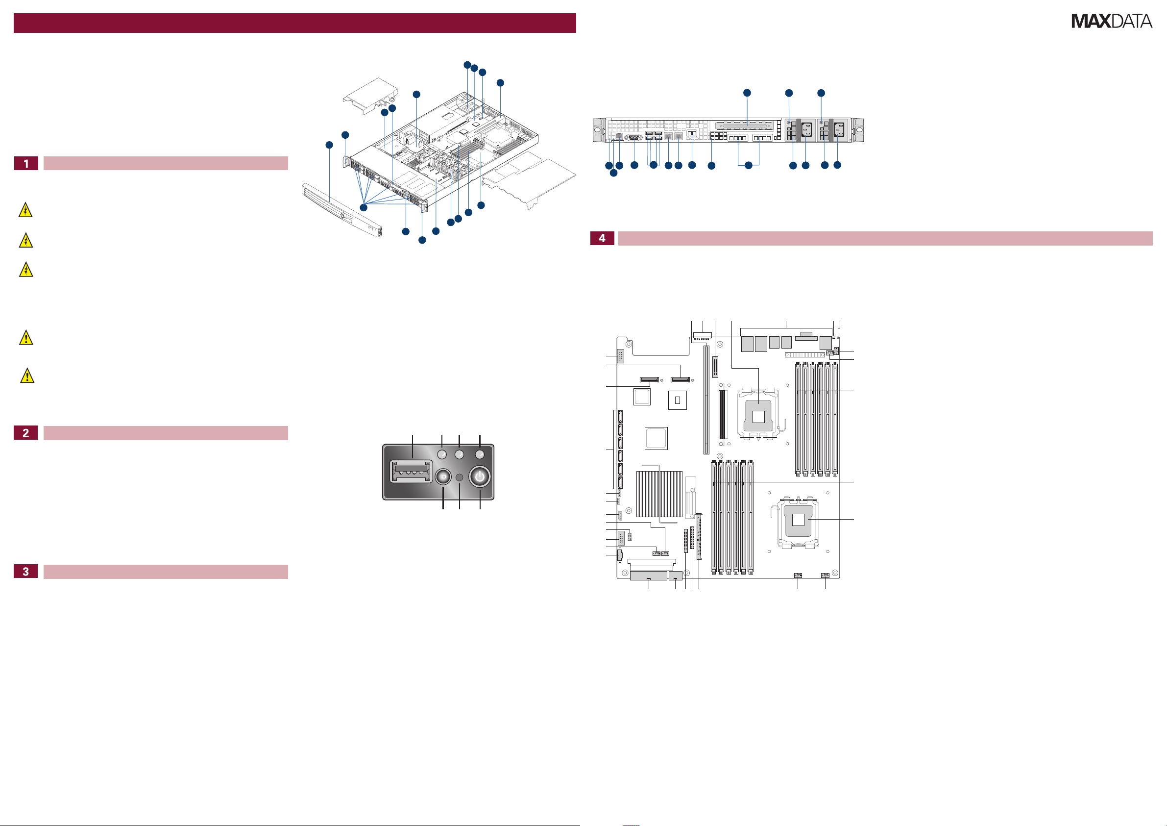
Chassis Components
Rear of Server System
1600 IR Server. This document describes how
to set up the system, turn on the system, and
complete configuration for the system.
Follow the link “User-Support und Treiber” on www.maxdata.de to access the download area and
download a more detailed guide.
Safety
Warning
Installation and service
Installation and service of this product is to be performed only by qualified service
personnel to avoid risk of injury from electrical shock or energy hazard.
Enclosure cover
In order to comply with applicable safety, emission, and thermal requirements, no covers
should be removed and all bays must be fitted with drive carriers.
Battery Safety
There is a danger of explosion if the battery is incorrectly replaced.
Dispose of used batteries in accordance with the manufacturer’s instructions and national
regulations.
Caution
Electrostatic discharge
Observe normal Electrostatic Discharge (ESD) procedures during system integration
to avoid possible damage to the server board and/or other components of the server
system.
Server system power
System power on/off: The power button DOES NOT turn off the system AC power. To
remove power from server system, you must unplug the AC power cord from the wall
outlet or the chassis.
A. Rack handles I. Processor and heatsink
B. Battery pack (optional) J. System memory
C. Slimline optical drive bay K. Bridge board
D. Power distribution board L. System fan bank
E. Power supply modules M. Midplane board (active version shown)
F. Server board N. Mini control panel
G. Intel® I/O expansion module
connector (optional)
H. Riser card assembly P. Front bezel (optional; standard control
O. Hard drive bays
panel shown)
Server Board Connector and Component Locations
Control Panel
Site Selection
The system is designed to operate in a typical office environment. Choose a site that is:
• Clean, dry, and free of airborne particles (other than normal room dust).
• Well-ventilated and away from sources of heat including direct sunlight and radiators.
• Away from sources of vibration or physical shock.
• Isolated from strong electromagnetic fields produced by electrical devices.
• In regions that are susceptible to electrical storms, we recommend you plug your system into a
surge suppresser and disconnect telecommunication lines to your modem during an electrical
storm.
• Provided with a properly grounded wall outlet.
• Provided with sufficient space to access the power supply cord(s), because they serve as the
product’s main power disconnect.
System Overview
Technical Specification
Dimensions:
- 43.2 mm high
- 430 mm wide
- 654,4 mm deep
- 21 kg - max chassis weight
System Power:
- 100-127 V at 50/60 Hz; 8 A max.
- 200-240 V at 50/60 Hz; 4 A max.
Temperature Range: +10 °C to +30 °C
Regulatory Compliance
This product complies to the following requirements:
- EN 60950 – Safety
- EN 55022 – Emissions
- EN 55024 – Immunity
- EN 61000-3-2 – Harmonics
- EN 61000-3-3 – Voltage Flicker
- CE – EMC Directive 89/336/EEC
This product has a CE declaration of conformity (CENELEC Europe).
This server system is compliant to European Directive 2002/95/EC (RoHS).
MAXDATA PLATINUM 1600 IR M2 Quick Start Guide
Callout Feature Function
A. USB 2.0 Port Allows you to attach a USB component to
the front of the system.
B. System Identification LED Solid blue indicates system identification
is active.
No light indicates system identification is
not activated.
C. System Status LED Solid green indicates normal operation.
Blinking green indicates degraded
performance.
Solid amber indicates a critical or nonrecoverable condition.
Blinking amber indicates a non-critical
condition.
No light indicates POST is running or the
system is off.
D. Power/Sleep LED Continuous green light indicates the
system has power applied to it.
Blinking green indicates the system is in
S1 sleep state.
No light indicates the power is off / is in
ACPI S4 or S5 state.
E. Power/Sleep Button Powers on/off the system.
Puts the system in an ACPI sleep state.
F. NMI Button Puts the server in a halt-state for
diagnostic purposes.
G. System Identification Button Turns on/off the system identification LED.
A. Full-height PCI add-in card slot J. Intel® Remote Management
Module NIC (optional)
B. Supply module #1 status LED K. NIC 2
C. Supply module #1 AC receptacle L. NIC 1
D. Supply module #1 M. Four USB ports
E. Supply module #2 status LED N. Video
F. Supply module #2 AC receptacle O. RJ-45 serial B connector
G. Supply module #2 (optional) P. System status LED
H. I/O module (optional) Q. System identification LED
I. POST code diagnostics LEDs
A. 280-pin Intel® Adaptive Riser Card slot Q. Fan board connector
B. POST code LEDs R. 2×4 power connector
C. Intel® RMM3 header S. Main power connector
D. Processor 1 T. Power supply SMBus connector
E. Back panel I/O U. Fan header
F. ID LED V. USB header
G. System status LED W. Solid state drive header
H. Fan header X. Fan header
I. Fan header Y. LCP IPMB header
J. Processor 1 DIMM slots Z. OEM IPMB header
K. Processor 2 DIMM slots AA. SGPIO header
L. Processor 2 BB. SATA connectors
M. Fan header CC. I/O module mezzanine connector 2
N. Fan header DD. I/O module mezzanine connector 1
O. Bridge board connector EE. Serial port B header
P. Front panel connector
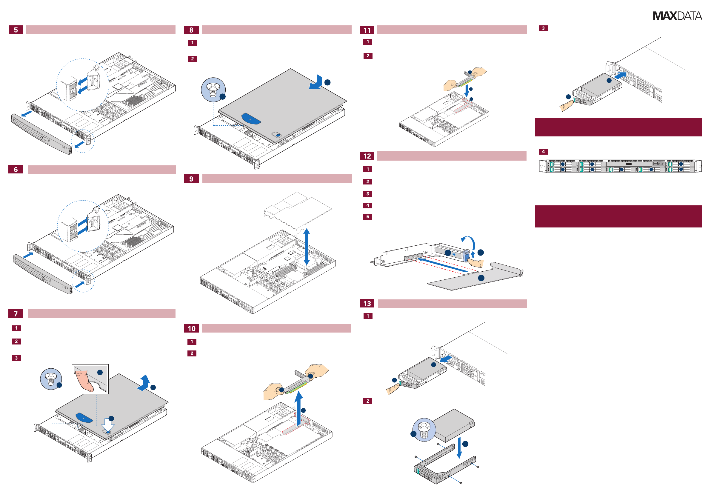
Removing the Front Bezel
D
A
C
B
A
B
A
B
A
B
A
B
5
6
7
2
3
1
0
4
A
B
A
A
B
C
B
B
A
Unlock the bezel and pull it from the server system.
Installing the Server System Cover
Place the cover over the server system so that the side edges of the cover sit just inside
the server system sidewalls.
Slide the cover forward until it clicks into place (see letter “A”).
Installing the PCI Add-in Card Riser Assembly
Align the three hooks in the riser assembly with the matching slots at the back of the
server system (see letter “B”).
Press down uniformly until the three hooks on the rear of the PCI riser assembly engage
the server system back panel slots. The riser cards will seat into the matching sockets on
the server board.
Installing a PCI Add-in Card
Install the Carrier Assembly.
Note
Carrier lever must be held in the FULLY OPEN position to install into chassis. Slide carrier into
chassis until it stops, then rotate the lever until it snaps shut.
Hard Drive Numbering Diagram
Installing the Front Bezel
Push the bezel onto the front of the server system until it clicks into place.
Removing the Server System Cover
Remove the safety screw if it is installed. See letter “A” in the figure below.
While holding in the blue button at the top of the server system in (see letter “B”), slide
the top cover back until it stops (see letter “C”).
Insert your finger in the notch (see letter “D”) and lift the cover upward to remove it.
Removing and Installing the Processor Air Duct
Removing the PCI Add-in Card Riser Assembly
Grasp both riser latches with thumb and forefinger (see letter “A”), and pull up to release
riser assembly.
Lift riser assembly straight up.
Open the rear retention clip by pushing the blue slide upward and rotating clip to the fully
open position (see letter “A”).
Open the front retention clip by rotating 90 degrees outward (see letter “B”).
Remove the filler panel from the selected add-in card slot (see letter “C”).
Insert add-in card until it seats in riser card connector (see letter “D”).
Close both retention clips.
Installing Hard Drives
Uninstall the disk carrier from the server chassis and remove the plastic baffle.
Drive 0 Primary Drive Bay
Caution
If you install less than 8 drives or devices, empty drive bays must be occupied by carriers with
baffles to maintain proper system cooling.
To avoid possible damage to your chassis, use only carriers that came with your server system.
Install the Hard Disk Drive.
Quick Start GuideMAXDATA PLATINUM 1600 IR M2
 Loading...