


MAXDATA PLATINUM 1510R Server Chassis
User‘s Manual

Contents

3
Working Inside Your Server
Tools and Supplies Needed
Warnings and Cautions

Figures
Tables
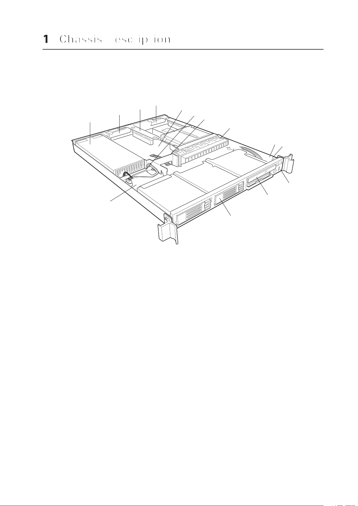
Figure 1. System Components
A.
Air baffle
J.
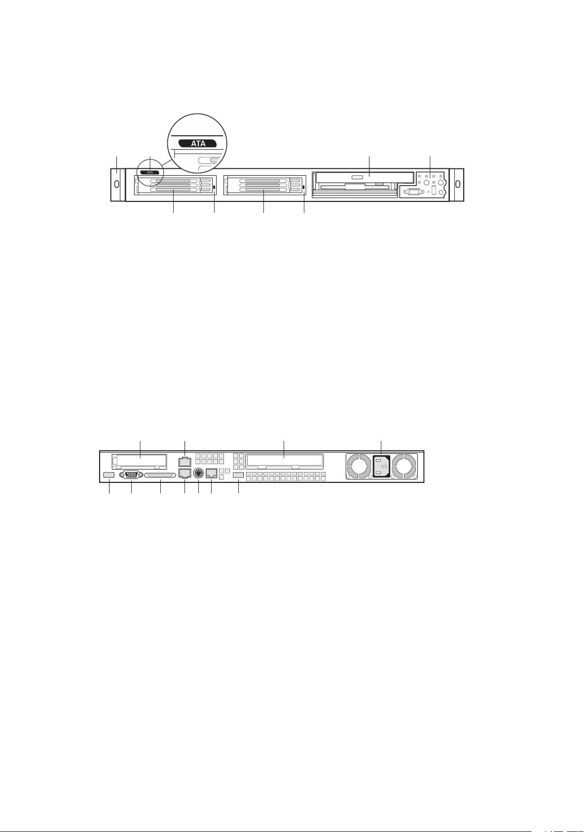
To access the system controls and peripherals when a front bezel is installed, grasp the
Yellow Status LED
Yellow Status LED
J.
Video connector

A.
J.
Video connector
Table 1. Control Button Functions
Toggles the system power on/off. Sleep button for ACPI-compatible operating
Toggles the front panel ID LED and the baseboard ID LED on/off. The baseboard
you are working on from behind a rack of servers.
When pressing the recessed button with a paper clip or pin, issues a nonmas-

Table 2. LED Indicator Status
which it is connected.
verable condition.
Notes:
The power LED sleep indication is maintained on standby by the chipset. If the system
Also off when the system is powered off or in a sleep state.
The amber status takes precedence over the green status. When the amber LED is on

The chassis provides for a variety of peripherals that can be purchased separately and added
A.
The chassis ships with two drive carriers for mounting HDDs in the hard drive bays.
In an ATA-based system, the ex bay can only be used with the optional DVD/FDD or
CD-ROM/FDD module. If the DVD/CD-ROM/FDD module is not used, the ex bay is left
empty. In a SCSI-based system, the ex bay can be used with either the optional DVD/FDD
or CD-ROM/FDD module or a third hot-swappable SCSI HDD.
The DVD/CD-ROM/FDD module may only be inserted or removed from the ex bay when
system power is turned off. The DVD/CD-ROM/FDD module is NOT hot swappable.

The power supply is rated for
The power subsystem supports implementation of remote management features including
The chassis includes a non-hot-swappable fan module with five fans for cooling the
To help prevent unauthorized access to the system’s peripherals and control panel,
To unlock the bezel, insert the key in the lock and turn the lock counterclockwise until it
To lock the bezel, insert the key in the lock. Turn the lock clockwise until it stops (about a

Anchor The Equipment Rack:
The equipment rack must be anchored to an unmovable
You are responsible for installing an AC power disconnect for
To avoid the potential for an electrical shock hazard, you
The server is designed for an AC line voltage source with up to 20
Temperature:
The operating temperature of the server, when installed in an equipment rack,
Ventilation:
The equipment rack must provide sufficient airflow to the front of the server

This chapter describes how to replace components in your server after it has been set up. All
Antistatic wrist strap (recommended)
Turn off all peripheral devices connected to the system.
Turn off the system by pressing the power button on the front of the system. Then
Attach a wrist strap to a chassis ground of the system – any unpainted metal surface –
These warnings and cautions apply whenever you remove the chassis cover to access compo-
WARNING

To allow proper airflow and cooling during operation, all drive bays must contain either a

A DVD/CD-ROM drive/FDD module is NOT hot swappable. Before replacing it, you must

Add-in cards must be replaced while the riser card is removed from the chassis.

Your server does not have a redundant power supply. Before replacing the power supply,
you must take the server out of service.


WARNING
You must adhere to the assembly instructions in this guide to ensure and maintain
The chassis subassembly, when correctly integrated per this guide, complies with the
The server chassis will be marked with the following regulatory compliance markings.
This device complies with Part 15 of the FCC Rules. Operation

This device complies with Part 15 of the FCC Rules. Operation is subject to the following two
This equipment has been tested and found to comply with the limits for a Class A digital
Any changes or modifications not expressly approved by the grantee of this device could
void the user’s authority to operate the equipment. The customer is responsible for ensuring
with FCC Class A or B limits may be attached to this computer product. Operation with
All cables used to connect to peripherals must be shielded and grounded. Operation with
This product has been tested in accordance too, and complies with the Low Voltage Directive
 Loading...