

Page 1

System Manual
MAXDATA PLATINUM 110 Server
Page 2

Contents
Page 3

3
Contents
®
875P Chipset
®
82875P Memory Controller Hub (MCH)
®
82801ER I/O Controller Hub (ICH5-R)
Video
AGP Connector
ATI Rage XL Video Controller
Video Modes
Wake-up Devices and Events
Wake from USB
Wake from PS/2 Devices
Page 4

®
Rapid BIOS Boot
The Controls
Tables
Video Modes
Wake-up Devices and Events
Page 5
1 Setting up the system
your computer:
The system can be used anywhere the temperature is suitable for people. However, rooms
with humidity over 70%, and dusty or dirty areas are not appropriate. In addition, do not
When you save data to your server‘s hard disks or to a floppy disk, they are stored as
ATTENTION
Page 6
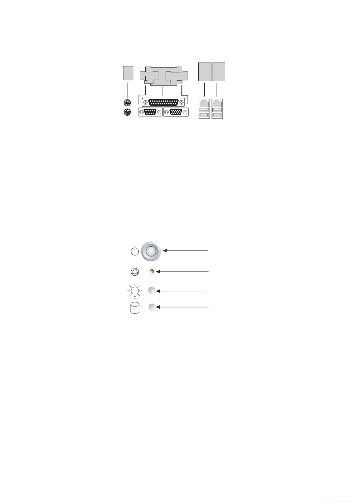
A.
VGA port
At the front of the case, you can find the neccessary controls like power button, reset button and the
Page 7
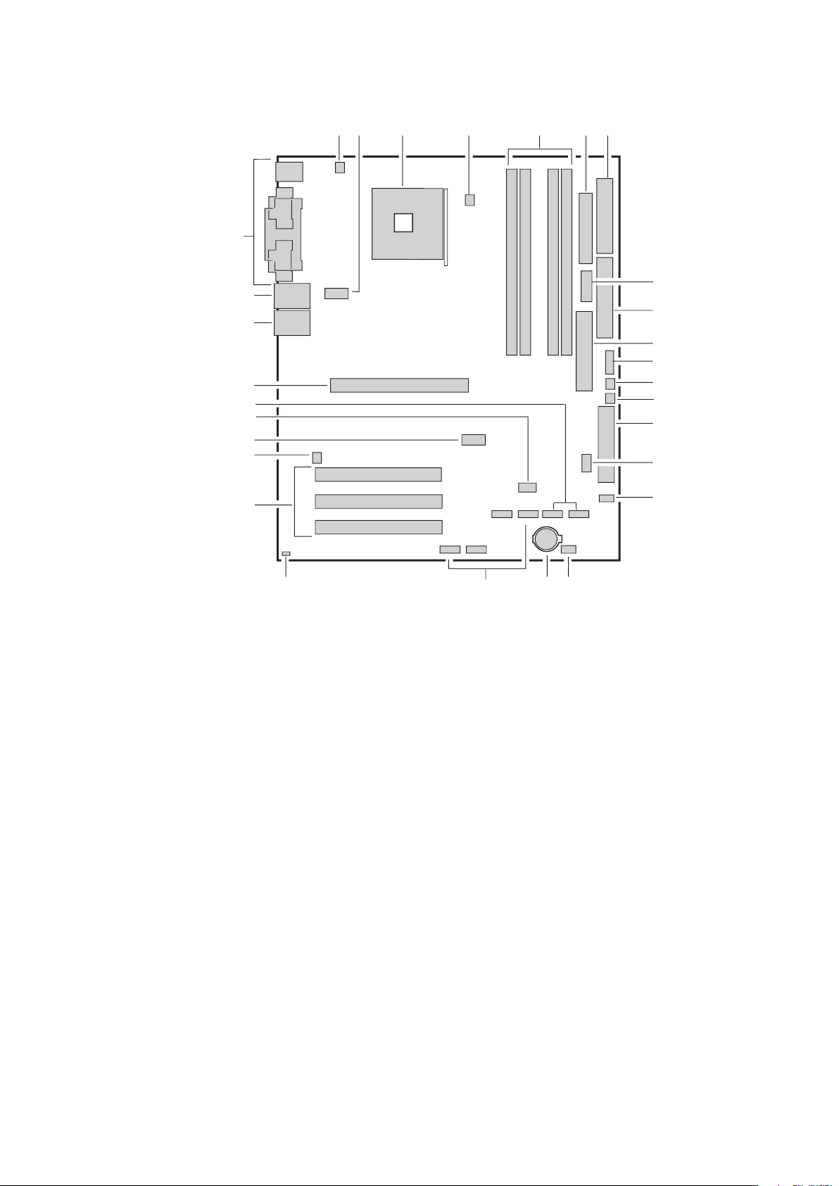
2 Server Description
This chapter briefly describes the main features of Intel
®
Server Board S875WP1-E.
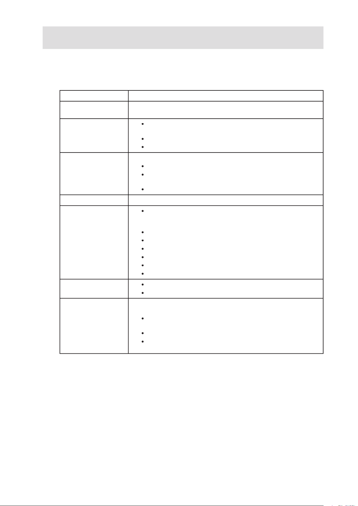
Table 1 summarizes the major features of the desktop board.
Table 1. Server Board Features
®
Pentium
®
4 processor in an mPGA478 package with
®
875P Chipset, consisting of:
®
82875P Memory Controller Hub (MCH).
®
82801EB I/O Controller Hub (ICH5-R) with support for up to
®
82802AC 8 megabit Firmware Hub (FWH).
Two IDE interfaces with ATA-66/100 support.
Two Serial ATA connectors.
®
82562ET 10/100 Fast Ethernet Controller.
®
82547EI Gigabit Ethernet Controller.
Accelerated Graphics Port (AGP) connector providing AGP 8x
Page 8
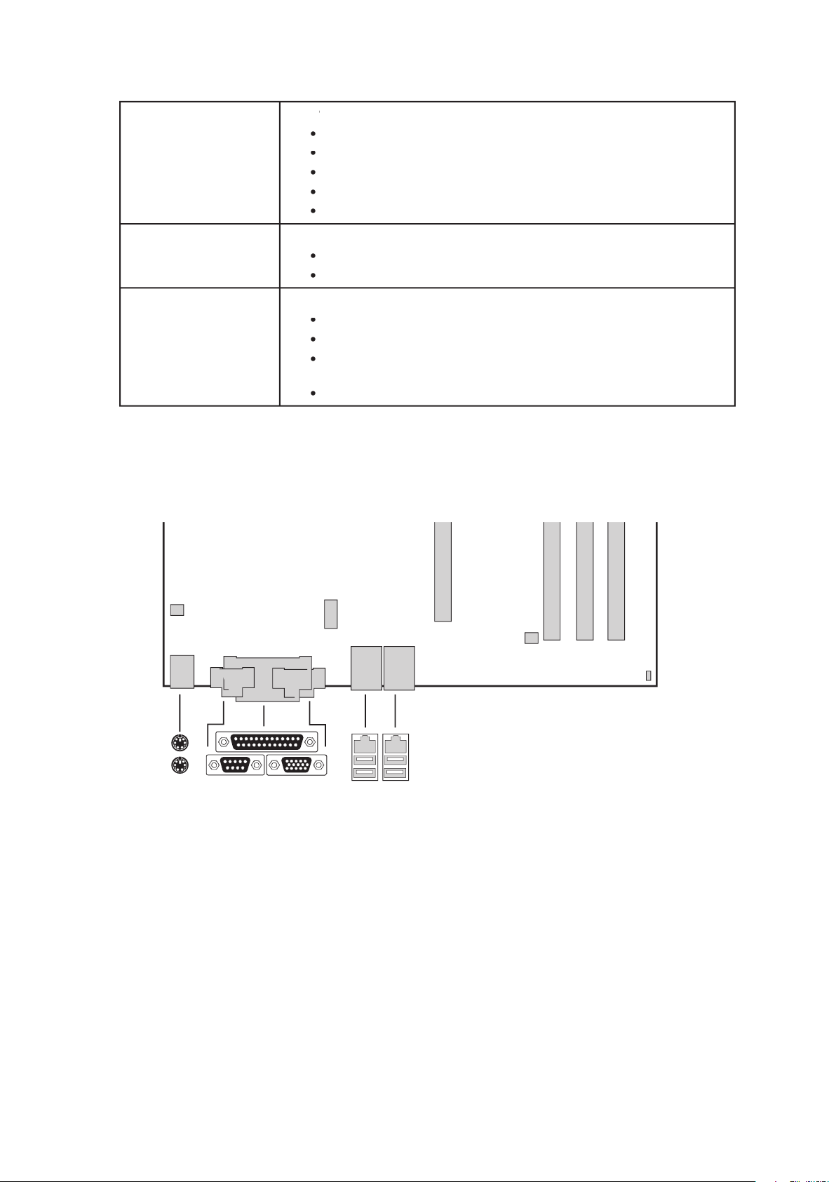
Table 1. Server Board Features (continued)
®
/AMI BIOS with support for:
Advanced Configuration and Power Interface (ACPI).
®
Rapid BIOS Boot.
®
Express BIOS Update.
Wake on USB, PCI, RS-232, PS/2, LAN, and front panel.
®
Precision Cooling Technology fan speed control that auto-
Voltage sensing to detect out of range values.
The back panel connectors are color-coded in compliance with PC 99 recommendations.
A.
Video port
Page 9
�
T.
V.
Auxiliary Power Connector
W.
J.
AGP Connector
AA.
Page 10

The S875WP1-E server board supports a single Intel Pentium 4 processor with an mPGA478 socket.
The processor connects to the server board through the mPGA478 socket. The Intel
®
Pentium
®
4
The server board S875WP1-E supports the following processors.
Table 2. Supported Processors
Type
®
4 processor with Hyper-
Threading (HT) Technology
®
4 processor
The S875WP1-E server board contains four 184-pin DIMM sockets and supports up to four DDR
®
Pentium
®
4 processor with
®
Pentium
®
4 processor with
®
Pentium
®
4 processor with 800 MHz FSB frequency.
®
Pentium
®
4 processor with
®
or a designated memory test vendor will be supported
on the board. Note that all DIMMs are supported by design, but only fully qualified DIMMs will be
supported. Mixed mode DDR DS-DIMMs (x8 and x16 on the same DIMM) is not supported.
Page 11

®
875P Chipset
The Intel
®
875P chipset consists of the following devices:
®
82875P Memory Controller Hub (MCH) with Accelerated Hub Architecture (AHA) bus.
®
82801ER I/O Controller Hub (ICH5-R) with AHA bus.
®
82802AC Firmware Hub (FWH).
The MCH is a centralized controller for the system bus, the memory bus, the AGP bus, and the
Accelerated Hub Architecture interface. The ICH5-R is a centralized controller for the board’s I/O
®
82875P Memory Controller Hub (MCH)
The MCH supports the data integrity features supported by the Pentium
®
4 processor bus, including
®
82547EI from the CSA interface.
The MCH provides the following:
An integrated DDR memory controller with auto detection.
AGP 2.0 slot, also known as AGP 8x.
®
82801ER I/O Controller Hub (ICH5-R)
The Intel
®
82801ER ICH5-R has these features:
®
8562ET) .
Page 12

Video
The server board S875WP1-E contains two separate, mutually exclusive graphics subsystems. You
AGP Connector
AGP is a high-performance interface for graphics-intensive applications. AGP is independent of the
AGP 3.0 specification.
The AGP connector on the server board S875WP1-E supports the following:
The AGP connector is keyed for 1.5V AGP cards only. Do not attempt to install a legacy 3.3V AGP
ATI Rage XL Video Controller
The S875WP1-E server board provides an ATI Rage XL PCI graphics accelerator, along with 8 MB
The SVGA subsystem supports a variety of modes, up to 1600 x 1200 resolution in 8/16/24/32 bpp
The server board S875WP1-E provides a standard 15-pin VGA connector and supports disabling of
Video Modes
The Rage XL chip supports all standard IBM VGA modes. The following table shows the 2D/3D modes
Page 13

Table 3. Video Modes
32 bpp
3D Mode
The SMSC LPC47M172 I/O Controller provides the following features:
The BIOS Setup program provides configuration options for the I/O controller.
The server board S875WP1-E has one serial port connector and one serial port header. The serial port
A connector is located on the back panel. The serial ports’ NS16C550-compatible UART supports data
A DH10 10-pin serial header is available on the baseboard for an option Serial B port.
Page 14

The 25-pin D-Sub parallel port connector is located on the back panel. In the BIOS Setup program,
The I/O controller supports one diskette drive that is compatible with the 82077 diskette drive controller
The keyboard is supported in the bottom PS/2 connector and the mouse is supported in the top PS/2
The keyboard controller contains the AMI keyboard and mouse controller code, provides the keyboard
The server board supports up to six USB 2.0 ports via the ICH5. Four ports are routed to the back panel.
Page 15

When the user applies power to the computer, legacy support is disabled.
The operating system loads. While the operating system is loading, USB keyboard and mice
After the operating system loads the USB drivers, all legacy and non-legacy USB devices are
To install an operating system that supports USB, verify that Legacy USB support in the BIOS
The primary I/O bus for the board S875WP1-E is PCI, with one independent PCI bus. The PCI bus
®
Three PCI slots
Table 4. PCI Bus Characteristics
Voltage
Width
Type
Page 16

The server board S875WP1-E supports Serial ATA devices using the ICH5-R controller. The ICH-5
The ICH5-R IDE controller has two independent bus-mastering IDE interfaces that can be independently
ATAPI devices (such as CD-ROM drives).
ATA-100/66: DMA protocol on IDE bus supporting host and target throttling and transfer
ATA-100/66 is a faster timing and requires a specialized cable to reduce reflections, noise, and
The IDE interfaces also support ATAPI devices (such as CD-ROM drives) and ATA devices using the
The BIOS supports Logical Block Addressing (LBA) and Extended Cylinder Head Sector (ECHS)
The S875WP1-E server board supports Laser Servo (LS-120) diskette technology through the IDE
ARMD-FDD (ATAPI removable media device – floppy disk drive)
ARMD-HDD (ATAPI removable media device – hard disk drive)
Page 17

The server board S875WP1-E supports two Network Interface Controllers (NICs), one that runs
®
82562ET NIC and the other that runs at one gigabit and is
®
82547EI NIC. When looking at the rear of the chassis, the gigabit NIC is at the
The 82562ET is controlled by the ICH5-R and supports the following features:
The 82547EI is controlled by the CSA interface off of the MCH. It supports the following features:
Automatic detection of “unplugged mode”.
Teaming and Fail over support.
Two LEDs are built into each RJ-45 LAN connector. For the 82562ET NIC, the yellow LED indicates a
when the board is powered up and the 82562ET 10/100 Ethernet LAN subsystem is operating.
Table 5. 10/100 Ethernet LAN Connector LEDs
Yellow
The computer is communicating with another computer
Table 6 describes the LED states when the board is powered up and the 82547EI 10/100/1000 Gigabit
Page 18

Table 6. 10/100/1000 Gigabit Ethernet LAN Connector LEDs
The computer is communicating with another computer
Yellow
Wake from USB
Wake from PS/2 keyboard/mouse
The Advance Configuration and Power Interface (ACPI) – aware operating system can place the
ACPI features include:
A soft-off feature that enables the operating system to power-off the computer.
Page 19

The Server Board S875WP1-E supports sleep states S0, S1, S2, S3, S4, and S5. When the server
The following is a summary of the supported sleep states:
while it was off.
The system is off only when the AC power is disconnected.
Table 7 lists the system states based on how long the power switch is pressed, depending on how
ACPI is configured with an ACPI-aware operating system.
Table 7. Effects of Pressing the Power Switch under ACPI
Wake-up
Page 20

Wake-up Devices and Events
Table 8 provides an overview of the devices or events that can wake the computer from specific
Table 8. Wake-up Devices and Events
These devices/events can wake up the computer…
The use of these wake-up events from an ACPI state requires an operating system that provides full
ACPI support. In addition, software, drivers, and peripherals must fully support ACPI wake events.
with ACPI in the following ways:
The PCI bus PME# signal for PCI 2.2 compliant LAN designs.
The onboard LAN subsystem.
When the PME# signal on the PCI bus is asserted, the computer wakes from an ACPI S1, S3, S4, or
Page 21

Wake from USB
Wake from USB requires the use of a USB peripheral that supports Wake from USB.
Wake from PS/2 Devices
The S875WP1-E server board provides several power management hardware features, including:
When used with an ATX12V or EPS12V compliant power supply that supports remote power on/off,
With soft-off enabled, if power to the computer is interrupted by a power outage or a disconnected
was interrupted (on or off). The computer’s response can be set using the After Power Failure feature
A standard ATX 20 pin power connector and standard ATX 12V 4-pin 2x2 connector can be used to
Page 22

Table 9 summarizes the function/operation of the fan connectors.
Table 9. Fan Connector Function/Operation
Wired to a fan tachometer input of the Hardware Management
ASIC.
fans (FAN1, FAN2,
Wired to a fan tachometer input of the Hardware Management
ASIC (Fans 1, 2, and 4 only).
The S875WP1-E server board supports the PCI Bus Power Management Interface Specification. An
The use of Instantly Available PC technology requires operating system support and PCI 2.2 compliant
The standby power indicator LED shows that power is still present even when the computer appears
Page 23

CR7J1
The Hardware Management features enable the board to be compatible with the Wired for
The server board S875WP1-E has an integrated Hardware Management ASIC that is responsible for
The LDCM software is for use with Windows
®
2000 Server and Windows
®
2000 Advanced Server
The BIOS includes security features that restrict whether the BIOS Setup program can be accessed
The supervisor password gives unrestricted access to view and change all Setup options.
viewing
and changing depending on whether the supervisor or user password was entered.
Page 24

Table 10. Supervisor and User Password Functions
The real-time clock provides a time-of-day clock and a multi-century calendar with alarm features. The
A coin-cell battery (CR2032) powers the real-time clock and CMOS memory. When the computer is
The time, date, and CMOS values can be specified in the BIOS Setup program. The CMOS values
Page 25

The S875WP1-E server board uses an Intel
®
/AMI BIOS that is stored in the Firmware Hub (FWH)
The S875WP1-E server board supports system BIOS shadowing, allowing the BIOS to execute from
The BIOS displays a message during POST identifying the type of BIOS and a revision code. The
When the S875WP1-E server board’s jumper is set to configuration mode and the server is powered-
Page 26

The BIOS can automatically configure PCI devices. PCI devices may be onboard or add-in cards. Auto
with independent I/O channel support. The IDE interface supports hard drives up to ATA-66/100
The BIOS determines the capabilities of each drive and configures them to optimize capacity and
To use ATA-66/100 features the following items are required:
An ATA-66/100 peripheral device.
An ATA-66/100 compatible cable.
ATA-66/100 operating system device drivers.
ATA-66/100-compatible cables are backward-compatible with drives using slower IDE transfer
The network can be selected as a boot device. This selection allows booting from the on-board NIC
Page 27

Video adapter
®
Rapid BIOS Boot
These factors affect system boot speed:
®
Rapid BIOS.
®
Rapid BIOS Boot
®
Rapid BIOS Boot. This feature bypasses memory count and the search for
This boot time may be so fast that some drives might be not be initialized at all. If this condition should
Page 28

Page 29

3 Regulatory and Integration Information
The server board S875WP1-E complies with the following safety requirements:
The server board S875WP1-E has been has been tested and verified to comply with the following
®
host system. For
®
representative.
This product is marked with the following Product Certification Markings:
Table 11. Product Certification Markings
Page 30

This device complies with Part 15 of the FCC Rules. Operation is subject to the following two conditions:
This equipment has been tested and found to comply with the limits for a Class A digital device,
will not occur in a particular installation. If this equipment does cause harmful interference to radio
Any changes or modifications not expressly approved by the grantee of this device could void the
A or B limits may be attached to this computer product. Operation with noncompliant peripherals is
This product has been tested in accordance to, and complies with the Low Voltage Directive (73/23/
When you install and test the server board, observe all warnings and cautions in the installation instruc-
To avoid injury, be careful of:
Page 31

There is insufficient space on this server board to provide instructions for replacing and disposing of
This server board was evaluated as Information Technology Equipment (I.T.E.) for use in computers
 Loading...