

Marmitek M229 Owner's Manual
20089 / 20070329 • M229
TM
© ALL RIGHTS RESERVED MARMITEK®2007
MARMITEK M229
DOORPHONE
SYSTEM
OWNER’S MANUAL 2
BETRIEBSANLEITUNG 18
NOTICE D’UTILISATION 34
GEBRUIKSAANWIJZING 50
• 2 WIRE SYSTEM
• BUILT-IN MEMORY (32 PICTURES)
WITH TIME AND DATE RECORDING
• UP TO 8 MONITOR STATIONS
• CONNECT UP TO 4 DOORCAMERAS AND
A MAXIMUM OF 3 DOME CAMERAS
ENGLISH
2 © MARMITEK
SAFETY WARNING
• This product is for professional use and should be installed by a certified installer.
• To prevent short circuits, this product (except the EX229D door unit) should only be used inside and
only in dry spaces. Do not expose the components to rain or humidity. Do not use the product close to
a bath, swimming pool etc.
• Only connect the adapter to the mains after checking whether the mains voltage is the same as the
values on the identification tags. Never connect an adapter or power cord when it is damaged. In that
case, contact your supplier.
• Do not expose the components of your systems to extremely high temperatures or bright light sources.
• Do not open the product: the device contains live parts. The product should only be repaired or
serviced by a qualified repairman.
• Do not open the product: the device contains live parts. The product should only be repaired or
serviced by a qualified repairman. In case of improper usage or if you have opened, altered and
repaired the product yourself, all guarantees expire.
• Marmitek does not accept responsibility in the case of improper usage of the product or when the
product is used for purposes other than specified. Marmitek does not accept responsibility for
additional damage other than covered by the legal product responsibility.
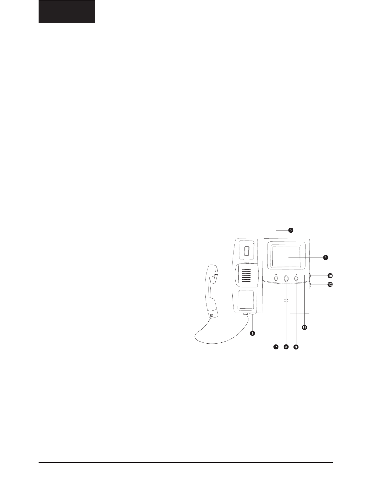
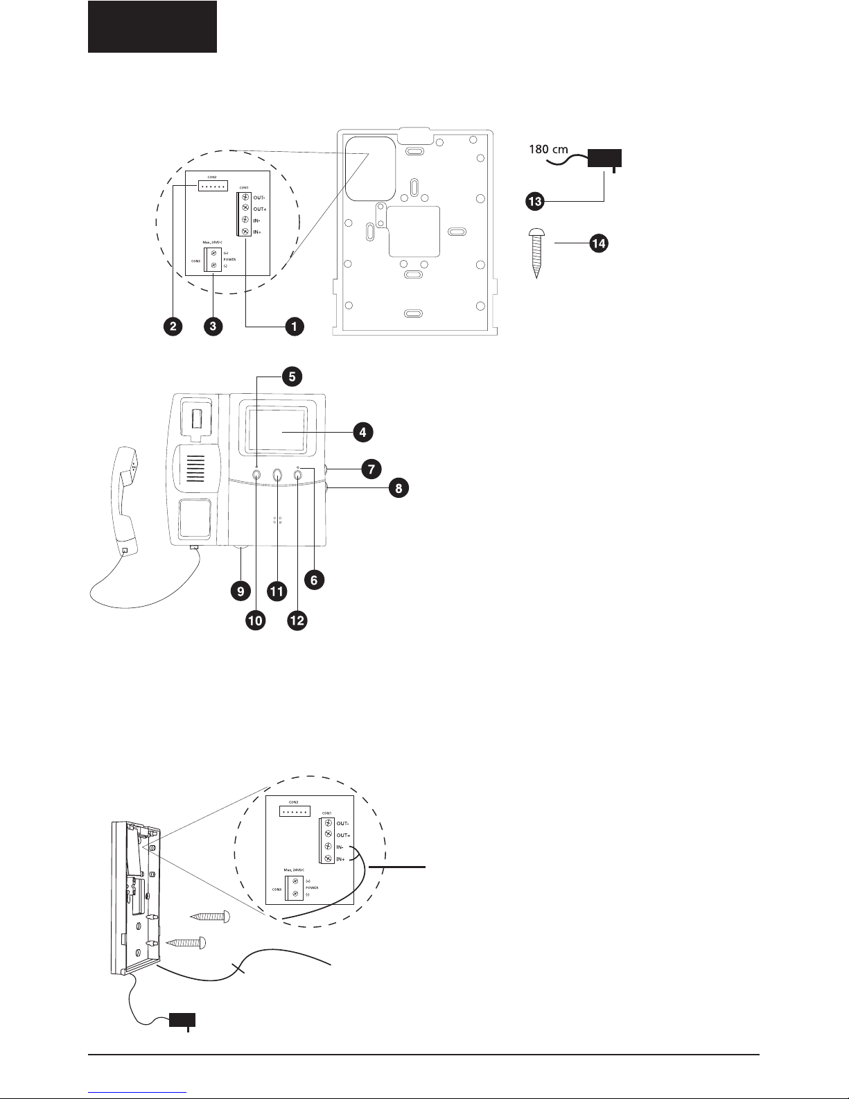
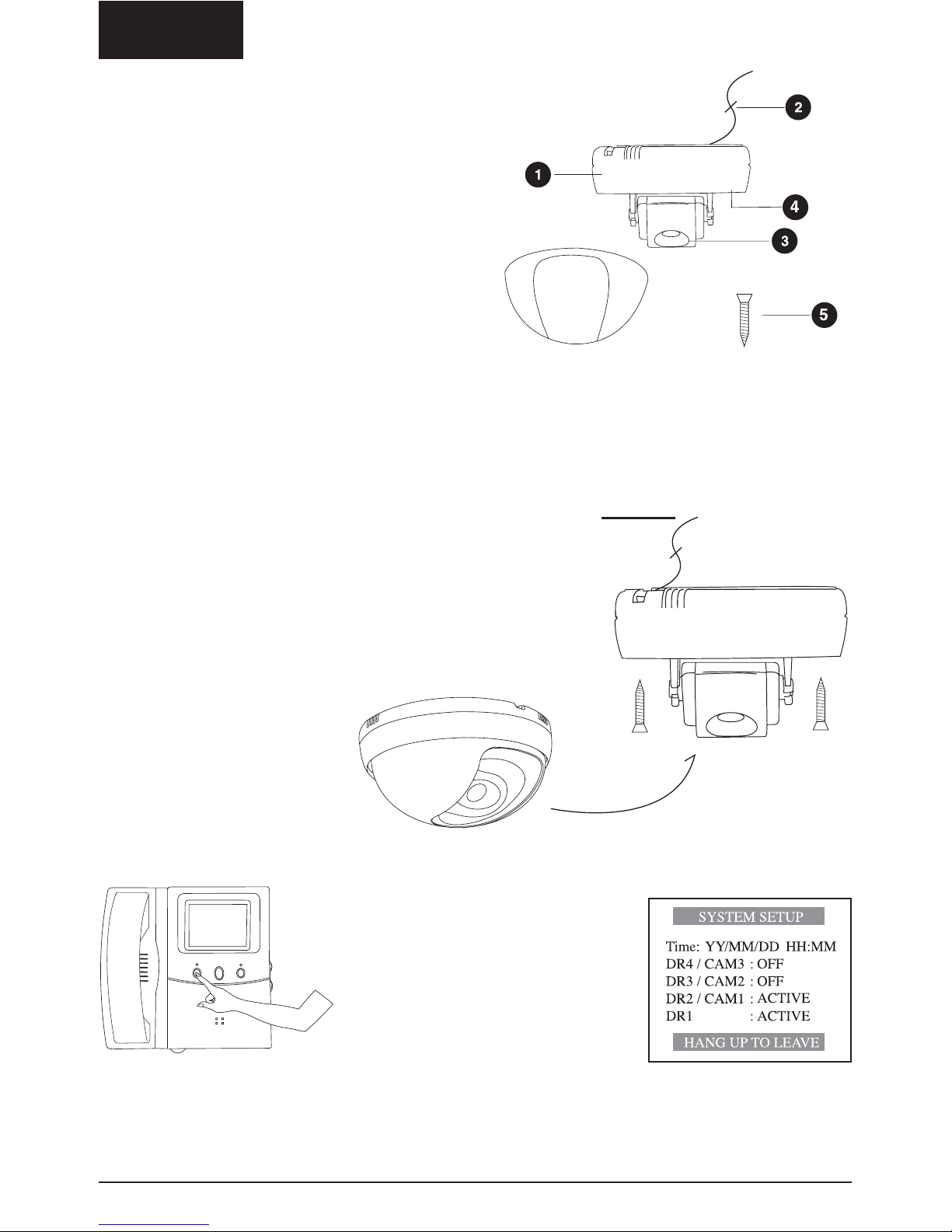
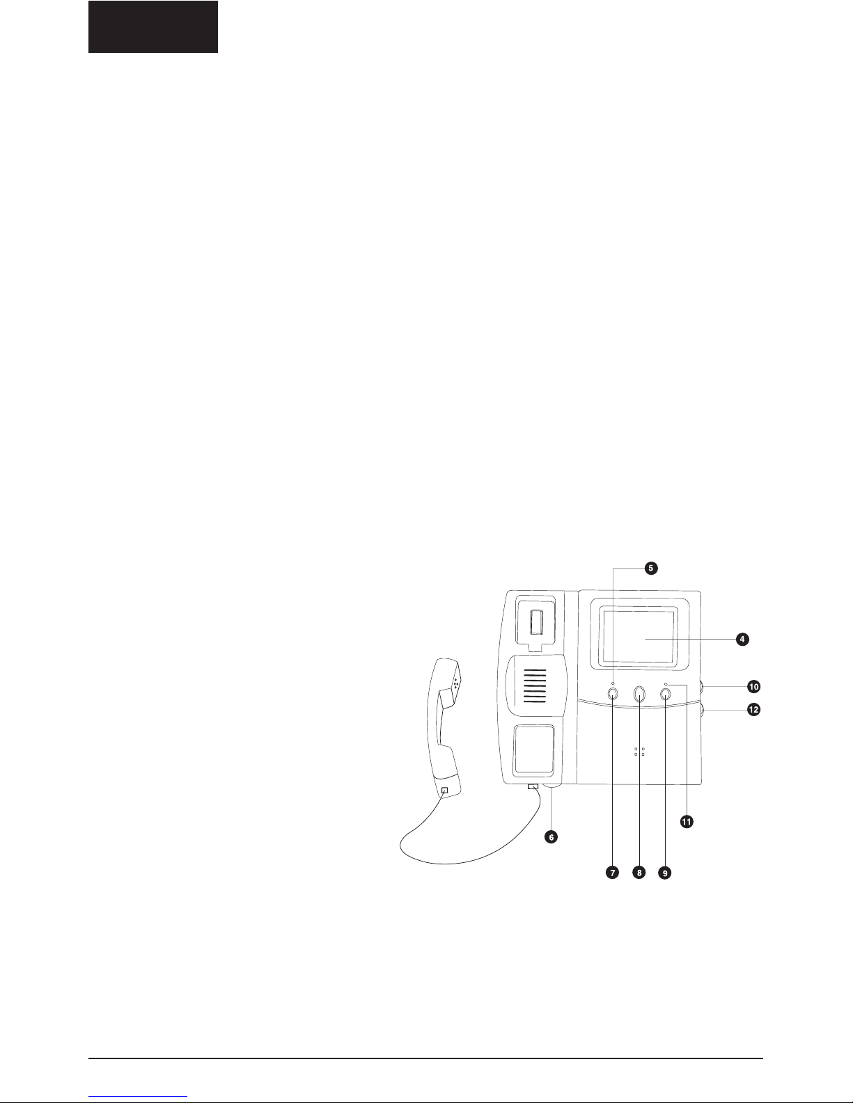
Operating controls:
1. Wiring Terminals
2. Connector Socket
3. DC Power Connection
4. 4" flat CRT
5. Power LED
6. Handsfree Volume Control
7. Intercom and Broadcast Button
8. Lock Release Button
9. Video and Audio Monitoring
10. Brightness Control
11. Memory Status LED
12. Contrast Control
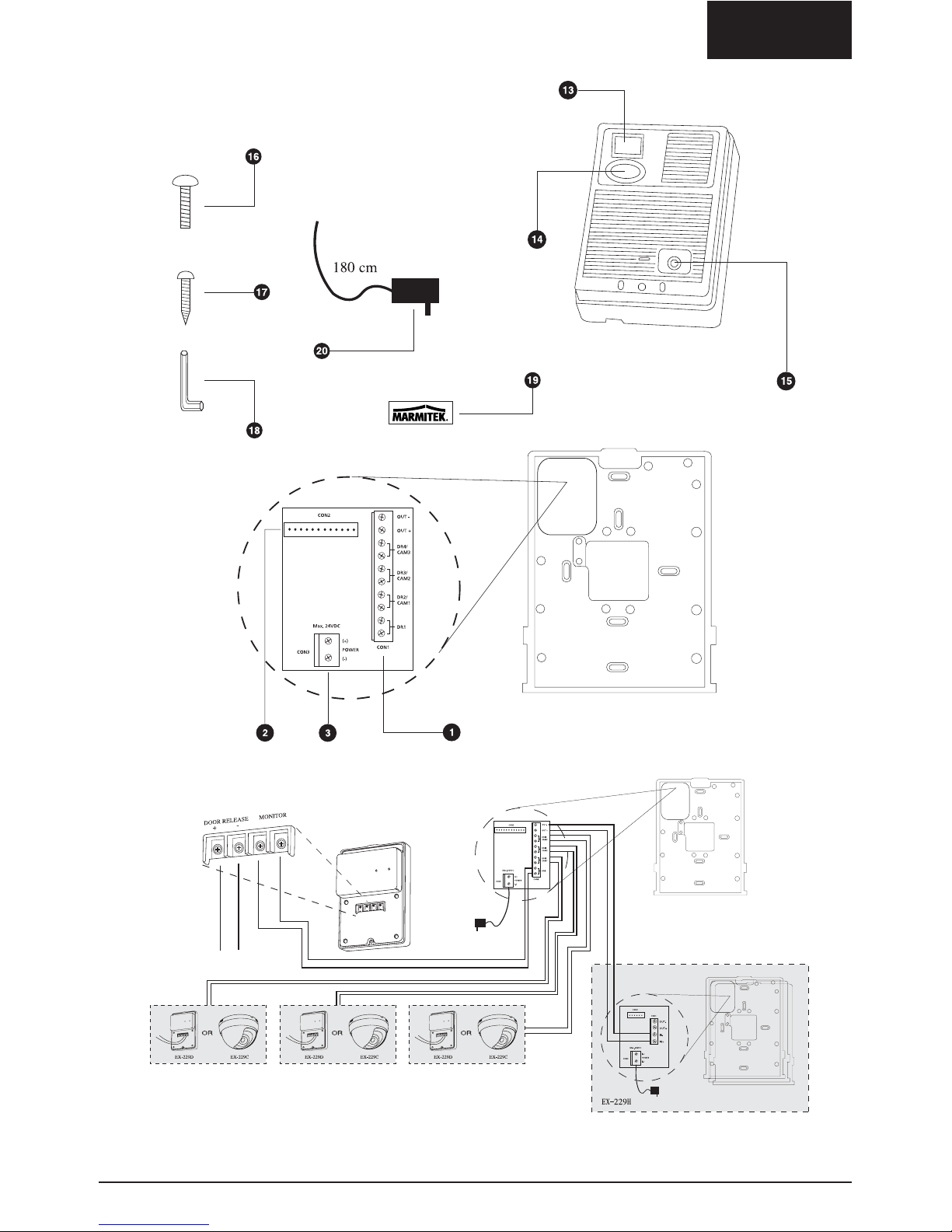
13. Infra Red Illumination LED’s
14. CCD Camera
15. Call Button
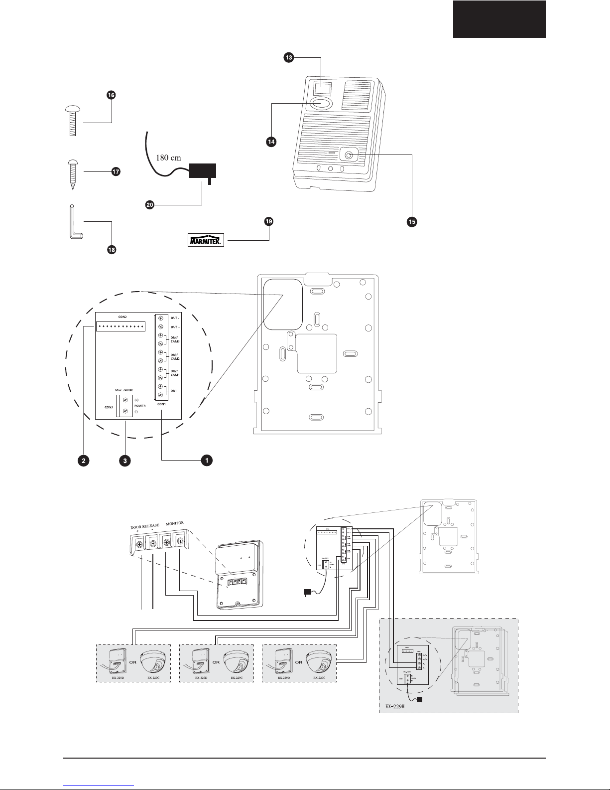
16. Door Unit Assembly Screw
17. Wall Mount Screws
18. Screw Wrench
19. Cover Label
20. AC Power Supply
MARMITEK 229 DOORPHONE SYSTEM
M229 Standard Parts
ENGLISH
WIRING DIAGRAM
3M229
™
Avoid wiring along AC cords
Lock Release Control
ENGLISH
4 © MARMITEK
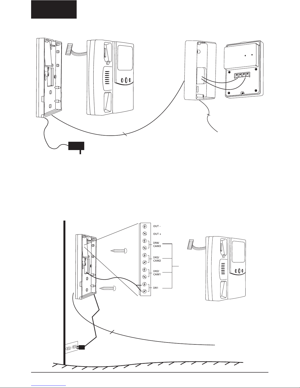
M229 BASE STATION INSTALLATION
STEP1:
Connect 2 wires to the DR1 screw connection for the door camera (no polarity. Use a 2-ply cable:
1,0 mm
2
for distances up to 100 m). Then connect the power adapter to the DC power adapter
connection [3] (+ = red, - = black). Do NOT connect the power adapter to the mains. Place the
base station onto the wall plate.
150-170 cm from ground
Connect the wiring for the doorunit to terminal DR1 (no
polarity)
To AC outlet: do not connect yet.
2 wires
2 wires to connect the Lock
Release Control (if available)
ENGLISH
5M229
™
Door camera
Power supply
24V/1A max
Electric door
lock
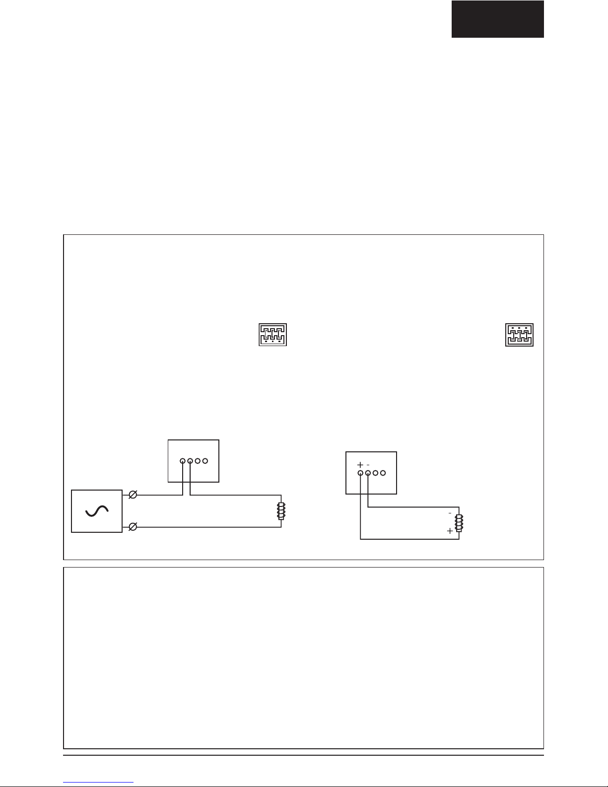
Door open output terminal
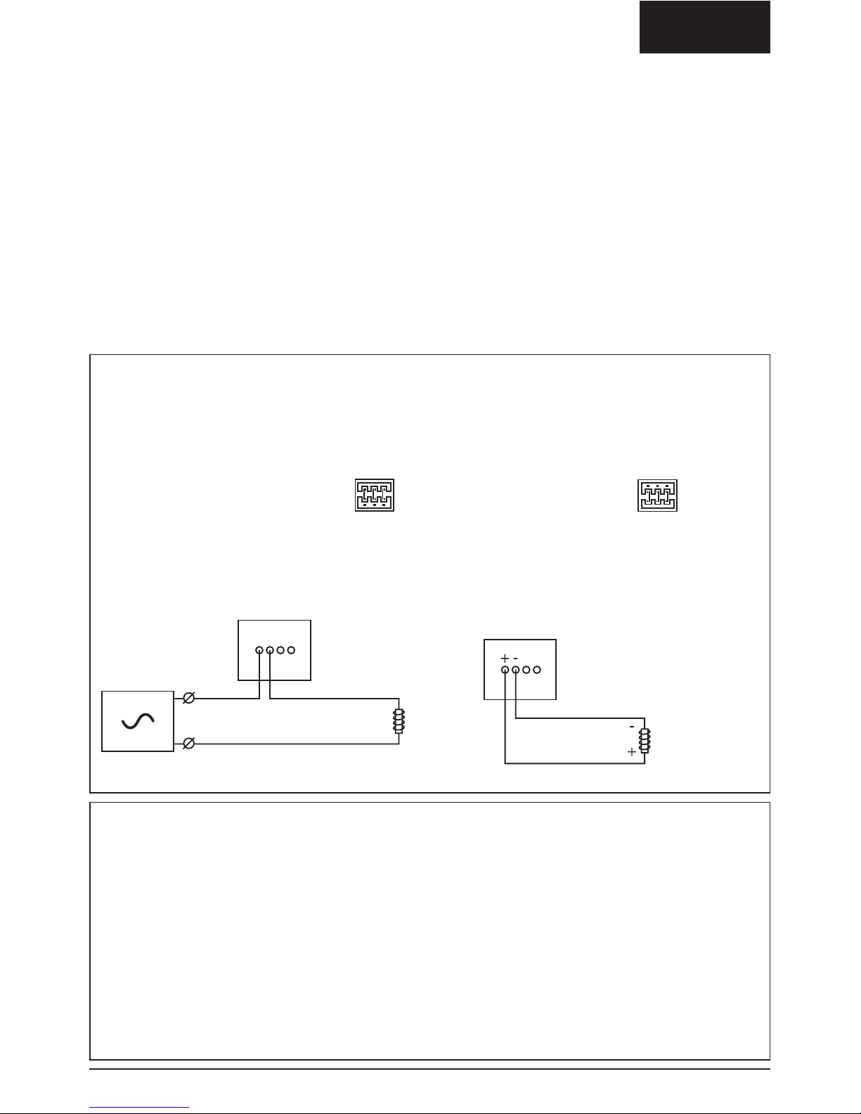
By pressing the middle button of the base station, an electric door lock can be controlled. The
door lock is connected to the DOOR RELEASE output terminals on the back of the door camera.
By repositioning the jumper at the back side of the camera you can toggle between two options:
1. Electric door lock with
its own power supply
(standard)
The door open contact is a dry contact.
Maximum load DC24V/1A or AC24V/1A.
Diagram:
2. Electric door lock
powered by
M229 system
The door open contact provides the power for
the electric door lock. Output voltage 12V,
maximum current 300mA. Diagram:
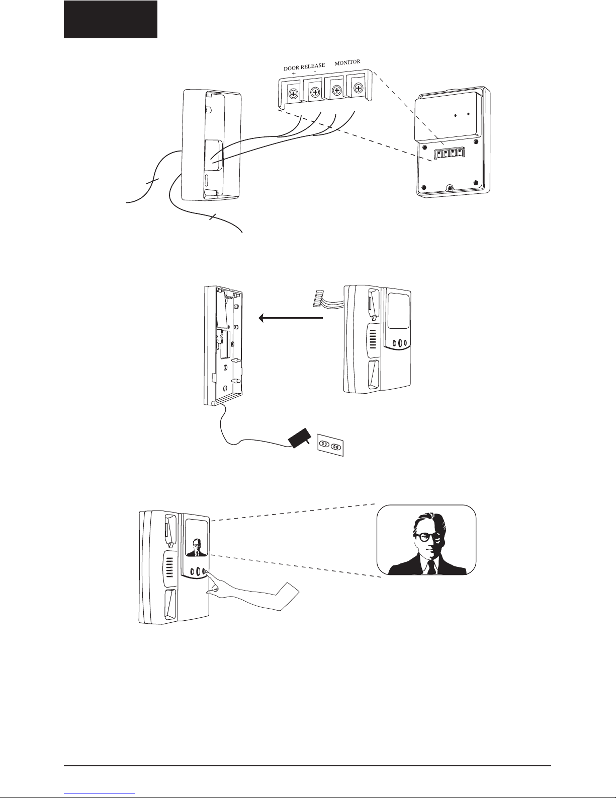
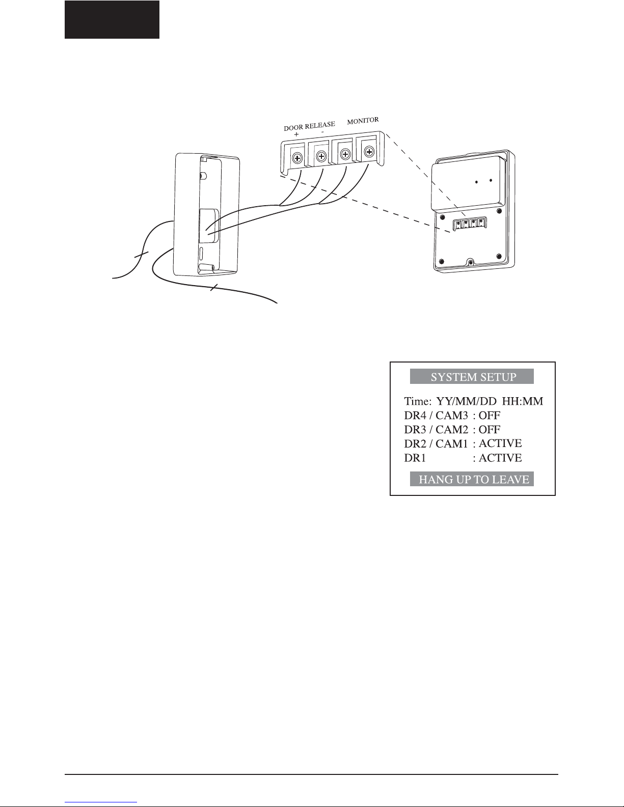
STEP 2:
To mount the door unit, first mount the metal Wall Plate. Connect the 2 wires from the base
station (monitor) to the terminals "MONITOR" (no polarity). If required, connect 2 wires for the
Lock Release Control to the terminals "DOOR RELEASE". See below for more details.
WARNING: The system will only work when a door camera is connected to connector DR1. If no
camera is connected to DR1, you cannot view any camera images or activate the menu.
Mount the door unit on the metal Wall Plate, using the screw (16) supplied.
See the description below for more information. An overview of all the connectors on the camera
can be found op page 17.
Connection for existing doorbell
An existing doorbell can be connected to the Marmitek EX-229D door camera, (part of the
Marmitek M229 system). As a result, the existing doorbell will be activated when the button of
the EX-229D camera is pressed.
To connect the doorbell system to the door camera, a small output terminal is available on the
back of the EX-229D door camera. A hook up wire for this terminal is supplied. You’ll find this
wire in the accessoires bag. The maximum voltage and current that can be switched with this
terminal (dry contact) is 12V/50mA.
The actual doorbell current of most doorbell installations is higher and therefore it has to be
switched with a relay. The relay is controlled by the extra output terminal of the camera.
Door camera
12V / MAX 300mA
Electric door
lock
6 © MARMITEK
ENGLISH
STEP 3:
Plug in the AC adapter of the base station (monitor)
STEP 4:
Press the Audio-Video Monitoring button (4) to test the system.
2 wires to DR1
terminals of the
Base station
(monitor)
2 wires to connect a Lock Release
Control (if available)

7M229
™
ENGLISH
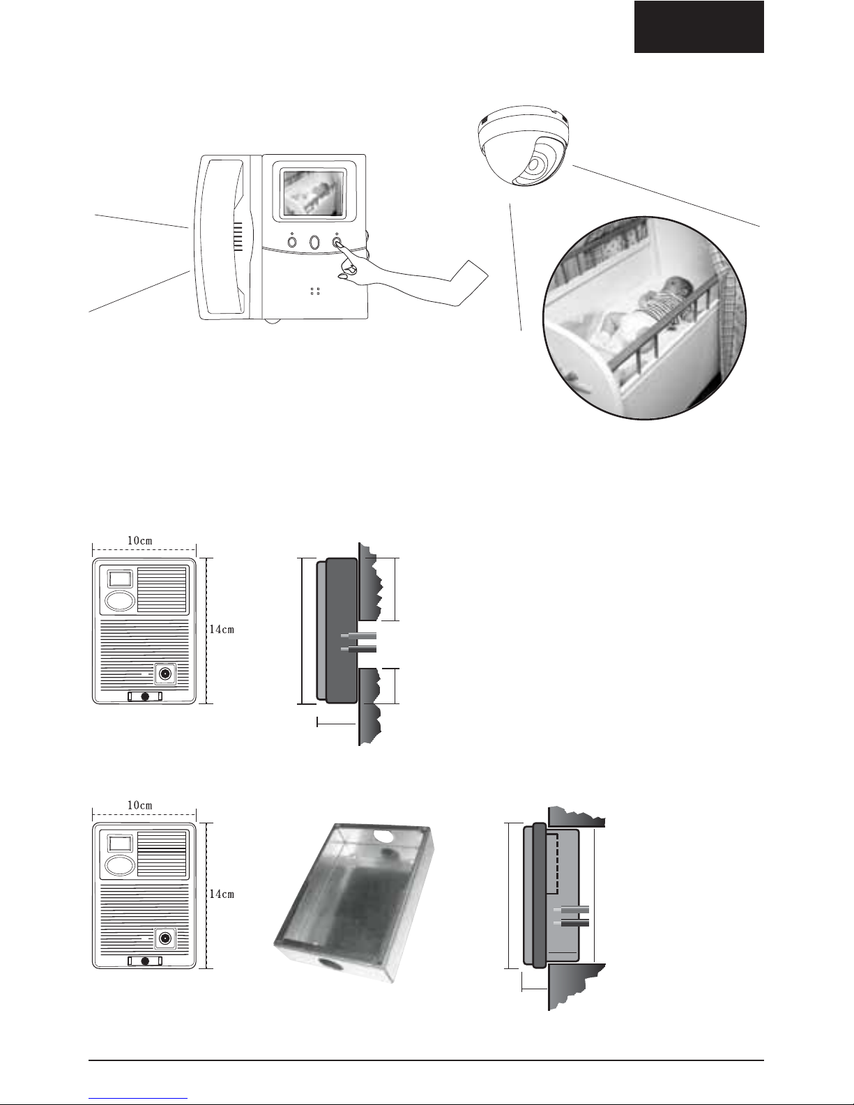
STEP 5:
Adjust the Viewing Angle of the Door Unit.
Use the supplied Screw Wrench,
and push the built-in camera unit
gently forward to adjust the angle
(use the left or right hole
respectively to adjust to the
required direction).
STEP 6:
Assemble the Door Unit.
Fix the screw (16) and use the adhesive label to cover the screw. Remove transparent protection.
8 © MARMITEK
ENGLISH
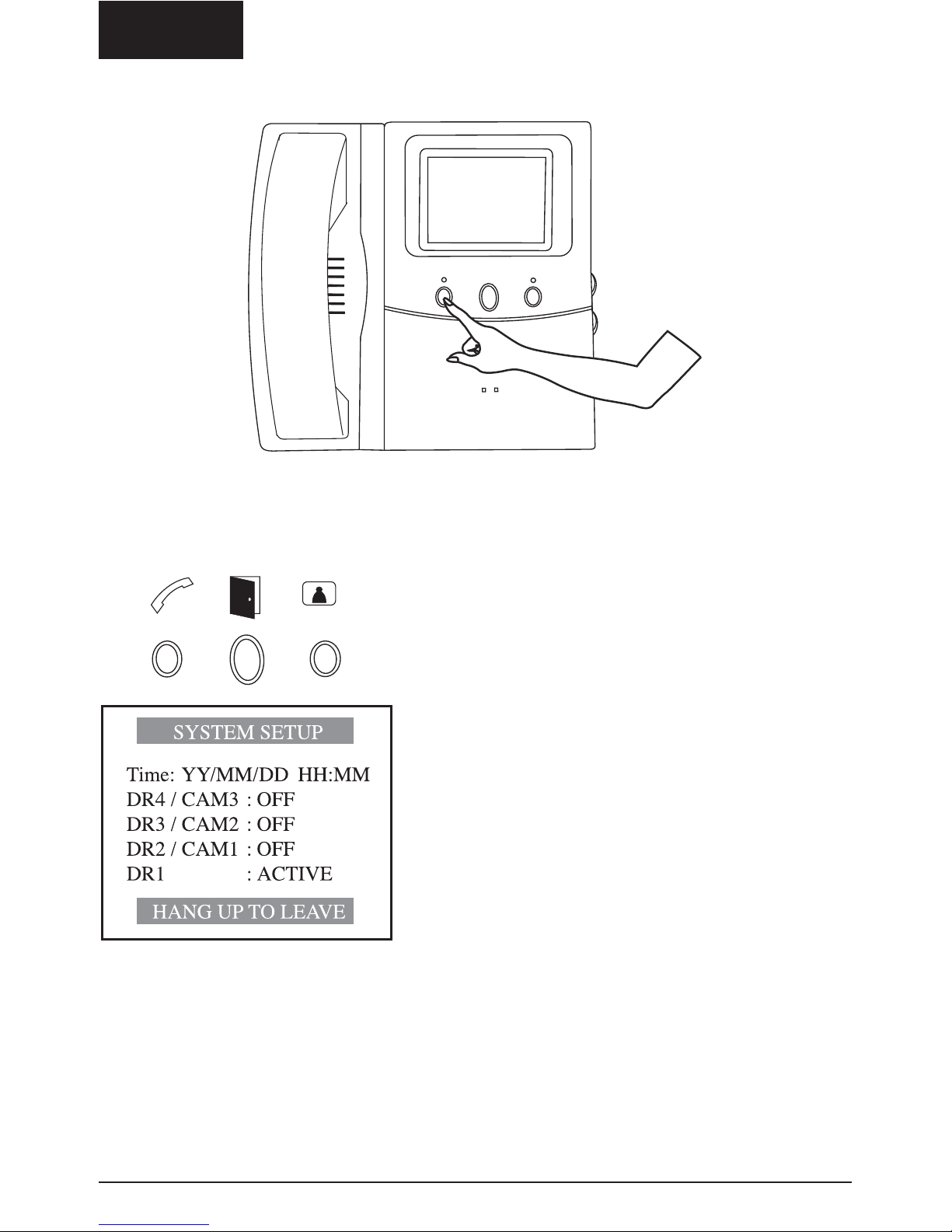
M229-BASE STATION SETUP
Press and hold the left button (7) for 2 seconds. A beep indicates the system is in Setup mode.
A Menu is displayed on the monitor.
By pressing the left (7) and right (9) buttons you can step
through the Menu options.
With the middle (8) button you can change the settings.
• When the Memory LED [11] flashes quickly, the time
and date settings have to be programmed. Format for
date and time: YY/MM/DD HH:MM. The built-in
back-up battery will retain the time, date and stored
pictures during 1 hour in case of power failure.
• In case of power failure the settings will be retained.
• DR4/CAM3, DR3/CAM2, DR2/CAM1 should remain in
OFF position if no expansions are installed.
• Pick up the handset en replace it to exit the
Set-Up mode.
9M229
™
ENGLISH
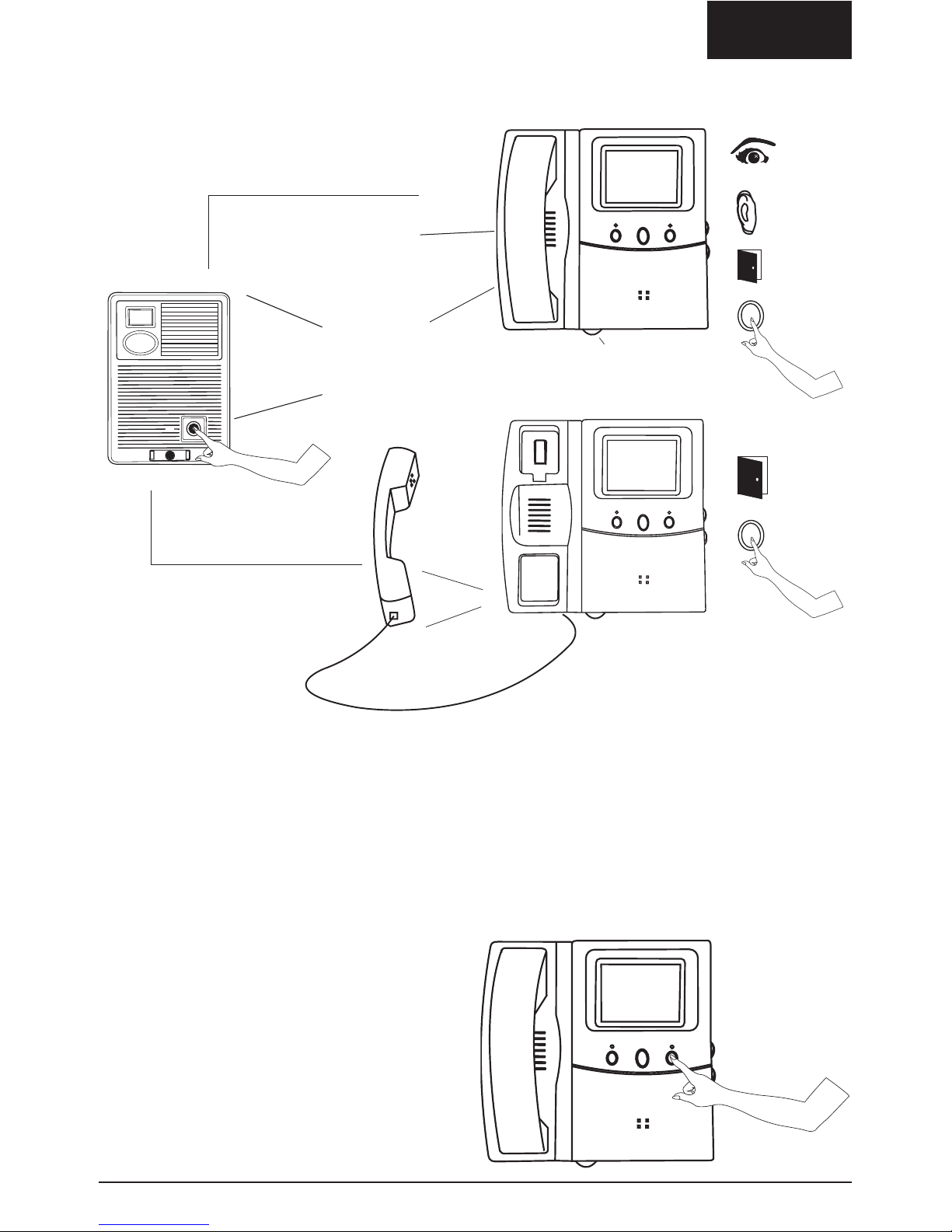
M229 – USING THE BASE STATION
1. Visitor calls from door unit:
•
After 4 seconds, the Marmitek
Video doorphone
automatically records
the picture in the memory.
• If the handset is not picked up, the connection will be automatically switched off 30 seconds
after the last call trigger.
• If the Handset is picked up, it will be switched off after 90 seconds, or earlier if the Handset is
replaced on the monitor unit.
• If the Handset is not activated (e.g. nobody home), the Memory LED (11) will slowly flash to
indicate that new pictures are stored in the memory.
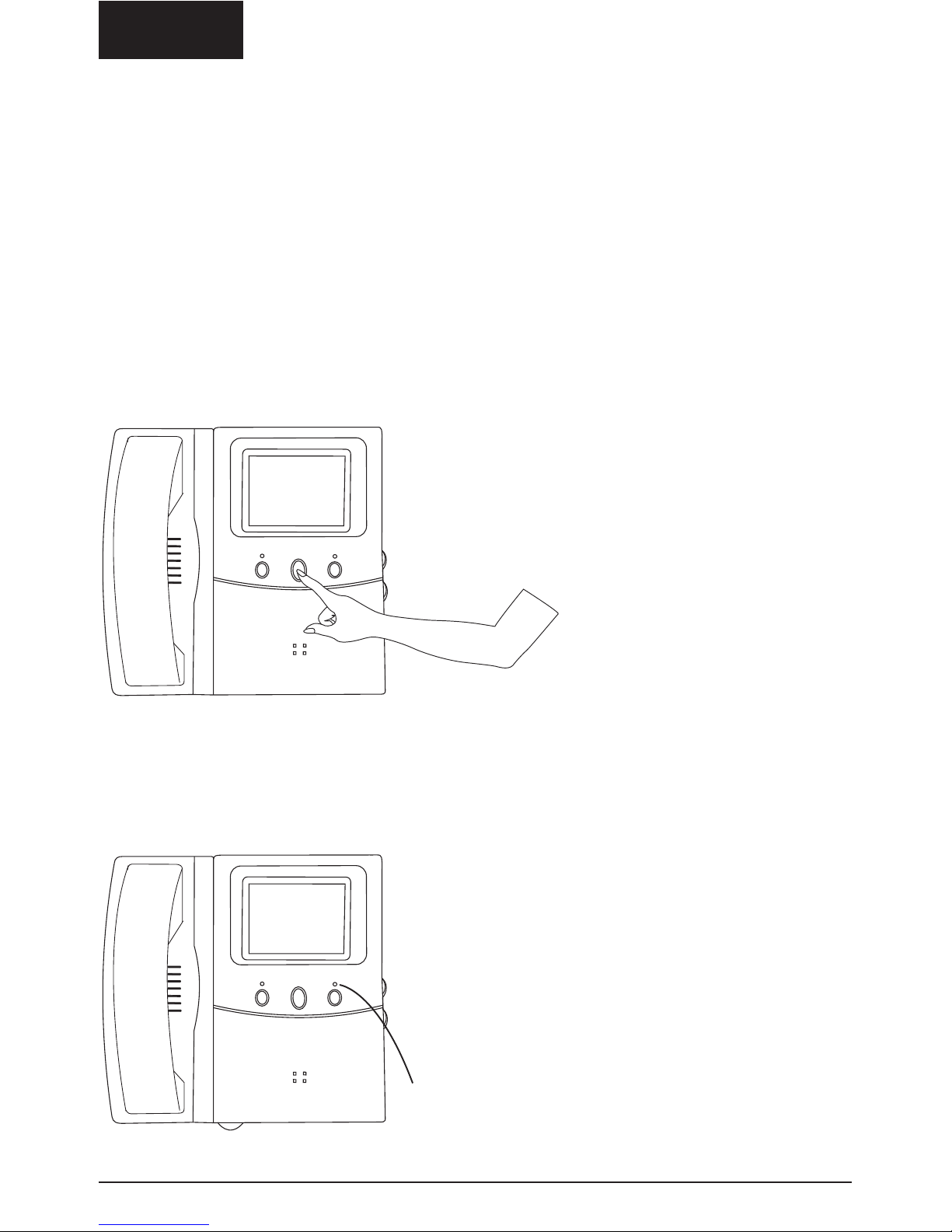
2. Audio and Video Monitoring without activitating the Handset.
• Press the right Button (9) for monitoring
without activating the Handset.
• If more Door units or cameras are connected,
you may select the required camera by
pressing the button 2, 3 or 4 times.
• The mode will automatically be exited after
90 seconds, or if the handset is picked up.
The mode will also be exited if a visitor calls
from the door unit.
DING DONG
DING DONG
Activation of
Audio and
Video.
Lock Release
Volume adjustment
(only for hands-free mode)
DING DONG
DING DONG
10 © MARMITEK
ENGLISH
3. Watching new pictures added to the memory
• If the Memory Status LED (11) is flashing slowly, a new picture (max. 32) has been captured.
• Press and hold the middle button (8) for at least 2 seconds. A beep indicates you are in Memory
mode. The most recently captured picture are displayed.
• With the right (9) button you can scroll through all the pictures in the memory.
The capture date and time is displayed for your information.
• New pictures are always stored in the memory. Older pictures then move down a space.
The picture last in line will disappear from the memory.
• The LED will stop flashing after you have watched all new pictures.
• In the top-right corner of the picture you can see which camera took this picture.
• To exit the Memory Mode, pick up the handset. The mode will also be exited if a visitor calls
from the door unit.
4. Other Functions:
• The Memory LED indicator (11) flashes (quickly) to indicate that a major power failure occurred
and the time and date need to be reset (See: M229 Base Station Set-Up).
Memory LED indicator
11M229
™
ENGLISH
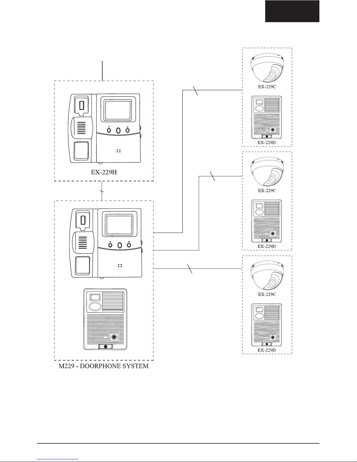
EXPANSION OPTIONS
Up to 8 monitor units
(1 base station + 7 slave monitors)
2 wires
2 wires
2 wires
EX-229H: Slave Monitor (no memory). Can also enable broadcasting and intercom functions.
Part. No. 09642
EX-229C: Dome camera for additional safety Part. No. 09643
EX-229D: Extra door camera for second, third or fourth door. Art. No. 09644
Use a 1.0 mm
2
cable up to 100 m for the two-ply connection for the door camera, as the door
opener needs extra electricity. All other two-ply connections can be 0.75 mm
2
up to 100 m.
2 wires
12 © MARMITEK
ENGLISH
EX-229H SLAVE MONITOR, PARTS IDENTIFICATION
EX-229H INSTALLATION
1. Terminals for connection to main unit and
next slave monitor
2. Pin Socket for monitor connection cable
3. DC Power jack
4. 4" Flat CRT
5. Power Connection
6. On Line (Busy) indicator
7. Brightness Control
8. Contrast Control
9. Volume Control for hands-free mode
10. Broadcast and intercom button
11. Lock Release
12. Audio and Video Monitoring button
13. AC/DC Power adaptor
14. Mounting screws
2-wire connection
From previous monitor (Main unit or
Slave unit) or next monitor (Slave Unit).
ATTENTION: connect with right polarity
(OUT+ to IN+ and resp. OUT- to IN-).
Standard wiring diagram: IN-/IN+ (Input) of
the next monitor to be connected with the
OUT-/OUT+ (Output) of the previous monitor.
EX-229H OPERATION SLAVE MONITOR
1. Visitor calls from door unit
• Operation similar to the Base Station M229.
• Right LED indicates other House Unit (Base or
Slave) is online with the door unit.
• When a visitor calls, any House Unit (Base or
Slave monitor) will disconnect other Monitor Units
when the handset is picked up.
• In the above situation other House Units (Base or
Slave) can join the conversation by pressing the
Monitoring Button (12).
• In the above situation you can invite other House
Units to join the conversation by pressing the left
button (10)
2. Monitoring Audio and Video without
picking up the handset.
• Operation similar to the Base Unit M229
• Press the right button (12) 1, 2, 3 of 4 times to
select the desired camera.
• The number of cameras to choose from depends
on the number of cameras activated on the Base
Unit M229 (max. 4 cameras).
• If more than one Monitor is set for monitoring,
camera selection is controlled by the Base Unit
M229.
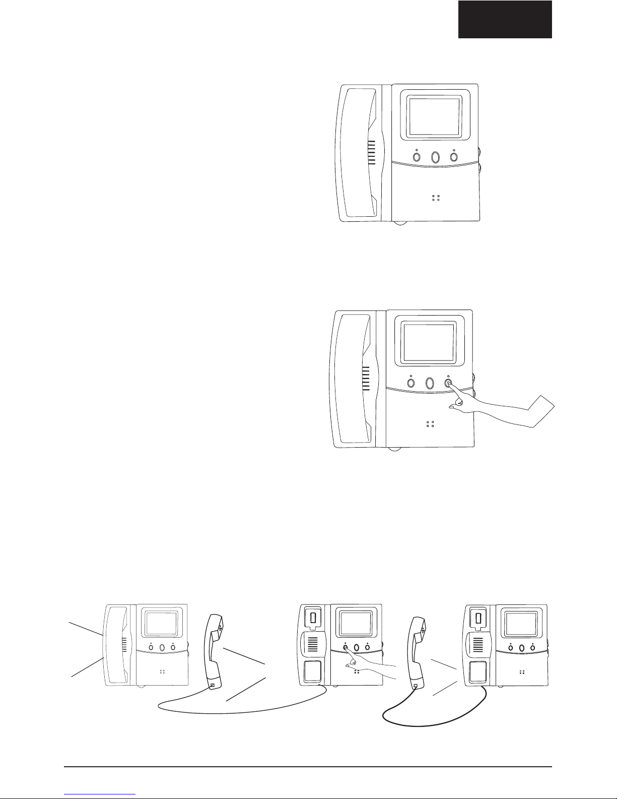
3. Intercom function
• Pick up Handset, press and hold the left button (10). A Call Beep can be send to all connected
House Units (both Base and Slave).
• Release the left button if anyone answers by picking up the handset. There is now an intercom
connection between the two House Units.
Call Beep
Hello
Call
Beep
13M229
™
ENGLISH
14 © MARMITEK
ENGLISH
EX-229C DOME CAMERA PARTS INDICATION
1. Microphone
2. Connection wires
3. CCD camera
4. Microphone Sensitivity Adjustment
5. Mounting Screws
If the camera is mounted in a small enclosed space, adjust the microphone sensitivity to a lower
setting.
EX-229C DOME CAMERA INSTALLATION
EX-229C DOME CAMERA SYSTEM SETUP
The camera is connected by a 2 wire cable to the
Base Unit. Additional Dome Camera’s can be
connected to the terminals DR4/CAM3 or
DR3/CAM2 or DR2/CAM1. There is no polarity.
• Press and hold the left button of the
Base Unit (7) for at least 2 seconds to
enter the Setup mode. The Menu
appears on the screen.
• Step through the menu
by pressing the left (7)
and right (9) button of
the Base Unit. Select
the camera
corresponding with the
Terminal number the
camera is connected to. Activate the camera by
pressing the middle button (8).
Pick up the Handset and replace it to exit the Setup
mode.
15M229
™
ENGLISH
EX-229C USING THE DOME CAMERA
Any House Units can activate the Dome Camera by
pressing the Monitoring Button. By repeatedly pressing this
button you can select the camera you want to use.
EX-229D DOOR UNIT PARTS IDENTIFICATION
For a semi flush mount system you need to use the optional IWB228/229 set (09416)
WALL MOUNT
SEMI FLUSH MOUNT
4,3
14
6,3
3,7
2,7
3,0
14 13,3
16 © MARMITEK
ENGLISH
EX-229D EXTRA DOOR UNIT INSTALLATION
You can connect up to 4 door camera’s to the M229 system. The button for the electrical door lock
works for the camera activated.
EX-229D SYSTEM SETUP FOR ADDITIONAL DOOR UNITS
• Press and hold the left button of the Main Unit (7) for at
least 2 seconds to enter in the Setup mode. The Menu
appears on the screen.
• Step through the menu by pressing the left (7) and right (9)
button of the Base Unit. Select the camera corresponding
with the Terminal number the camera is connected to.
Activate the camera by pressing the middle button (8). Pick
up the handset and replace it to exit the setup mode.
Handset and replace it to end the Setup mode.
EX-229D USING THE 2nd, 3rd AND 4th DOOR UNIT
The EX-229D functions in exactly the same way as the first camera connected to the Base Unit.
AUDIO / VIDEO OUT
The main monitor of the M229 system has an audio/video out. This connection makes it possible to
view camera images on a TV or video monitor. The M229 can also be connected to a recorder or
PC with video in. This function does not work with the built-in memory.
A connecting wire is included. The colour codes are:
White: Audio out Black: GND (mass for audio and video)
Yellow: Video out Brown: AV OUT trigger
The AV OUT trigger contact is a NO (normally open) contact. When the monitor is activated, the
contact is closed. You can use this contact to e.g. start a VCR.
When you want to extend the cable, you need to use a shielded or coax cable.
2 Wires to connectors
of the Main Unit
2 Wires to connect the Lock Release Control (if available).
17M229
™
ENGLISH
SPECIFICATIONS MARMITEK
M229 DOORPHONE SYSTEM
Monitor
CRT: 4" flat screen CRT
TV system: B/W CCIR
Resolution: Over 420 TV lines
Power for the monitors
Free Voltage Switched Mode Power Supply
100V ~ 240V AC
DC 24V / 0,75 A max
Cable length between power adapter and
monitor
Standard: 180cm
Extendable to max. 5 m when using a
1 mm
2
cable .
Cable type: stranded wire
Wiring Distance Reference
<50 meter: 0,5 mm
2
50-100 METER: 0,75MM
2
Cable type: 2-ply. The most suitable cable type is
a cable with a stranded wire. For distances up to
50 m, a cable with a massive wire can also be
used. UTP and CAT5 cables are not suitable.
Connected wires to achieve the proper diameter
does not work.
Camera’s
Resolution: 380 lines
CCD: 1/3", auto shutter
TV system: B/W CCIR
Angle Lens: Wide Angle 78 degrees
(F3,5)
Lightsensitivity: Doorcamera: 0 Lux
(IR lighted)
Dome camera 2 lux
Dimensions (wxhxd)
EX229 Mains Station: 335x220x75mm
EX229H Slave Station: 335x220x75mm
EX229D Door Unit: 100x140x42mm
EX229C Dome Camera: 90x90x90mm
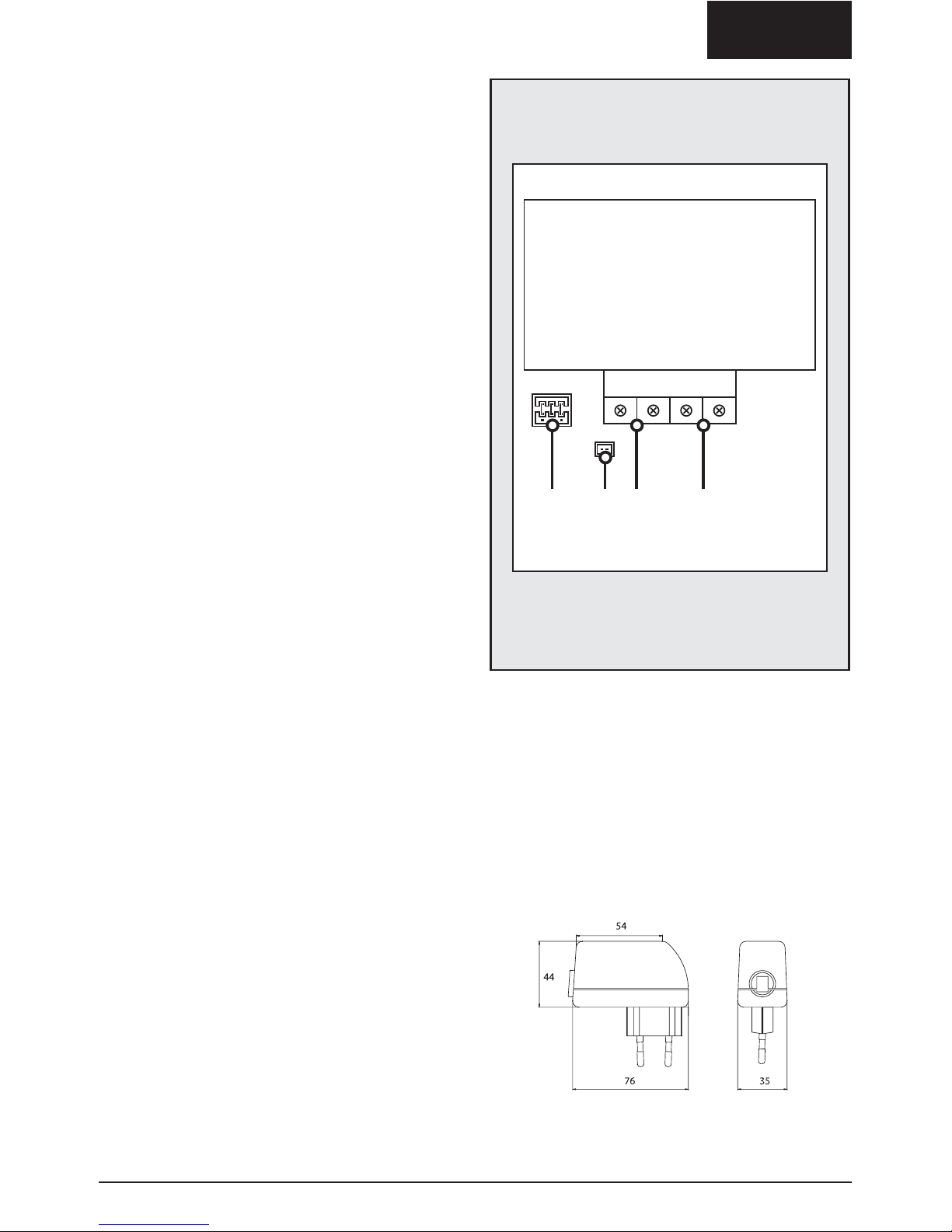
Power adapter main monitor and slave monitor
(EU version):
BACK SIDE OF
THE CAMERA
A JUMPER DOOR OPEN CONTACT
B CONNECTION FOR EXISTING DOORBELL
C CONNECTION ELECTRIC DOOR LOCK
D CONNECTION MONITOR
ABC D
EX229D
DEUTSCH
1. Schraubanschlüsse
2. Verbindungsconnector
3. Anschluss für DC Netzteil
4. 4" flacher Bildschirm
5. LED Einschaltanzeige
6. Lautstärkeregler für Freisprecheinrichtung
7. Intercom-Taste
8. Türöffnertaste
9. Monitor Aktivierungstaste (Bild und Ton)
10. Helligkeitsregler
11. LED-Anzeige für Speicher
12. Kontrastregler
13. Infrarot LED-Anzeige
14. CCD-Kamera
15. Türklingel
16. Schraube zur Endmontage der Türkamera
17. Befestigungsschrauben
18. Schlüssel zur Montage der Türkamera
19. Etikett
20. Netzteil
18 © MARMITEK
SICHERHEITSHINWEISE
• Dieses Produkt ist für den professionellen Gebrauch vorgesehen. Installation muss durch einen
anerkannten Installateur erfolgen.
• Um Kurzschluss vorzubeugen, dieses Produkt bitte (ausgen. der M229D Außenkamera selbst)
ausschließlich innerhalb des Hauses und nur in trockenen Räumen nutzen. Setzen Sie die
Komponenten nicht Regen oder Feuchtigkeit aus. Nicht neben oder nahe eines Bades,
Schwimmbades usw. verwenden.
• Schließen Sie den Netzadapter erst an das Stromnetz an, nachdem Sie überprüft haben, ob die
Netzspannung mit dem angegebenen Wert auf den Typschildern übereinstimmt. Schließen Sie
den Netzadapter oder die Netzschnur niemals an, wenn diese beschädigt sind. Nehmen Sie in
diesem Falle mit Ihrem Lieferanten Kontakt auf.
• Setzen Sie die Komponente Ihres Systems nicht extrem hohen Temperaturen oder starken
Lichtquellen aus.
• Das Produkt niemals öffnen: Das Gerät enthält Bestandteile mit lebensgefährlicher
Stromspannung. Überlassen Sie Reparaturen oder Wartung nur Fachleuten.
• Bei einer zweckwidrigen Verwendung, selbst angebrachten Veränderungen oder selbst
ausgeführten Reparaturen verfallen alle Garantiebestimmungen. Marmitek übernimmt bei einer
falschen Verwendung des Produkts oder bei einer anderen Verwendung des Produktes als für
den vorgesehenen Zweck keinerlei Produkthaftung. Marmitek übernimmt für Folgeschäden
keine andere Haftung als die gesetzliche Produkthaftung.
MARMITEK M229 VIDEOTÜRTELEFON:
BESCHREIBUNG DER TEILE
DEUTSCH
VERDRAHTUNGSSCHEMA
19M229
™
ACHTUNG: Um Störungen zu vermeiden darf die Bekabelung nicht in der Nähe eines 230V
Stromanschlusses angebracht werden.
Elektrisches
Türschloss

DEUTSCH
20 © MARMITEK
M229 BASISSTATION INSTALLATION
SCHRITT 1:
Vor Montage des Videotürtelefons bringen Sie zuerst die Wandplatte an und schliessen die
Bekabelung lt. Anschlussschema an. Für die Türkamera schliessen Sie 2 Drähte an die DR1
Schraubanschlüsse an (1,0 mm
2
bis 100m). Anschliessend schliessen Sie das Netzteil an den
Anschluss für das DC-Netzteil an [3] (+ = rot, - ist schwarz). Schliessen Sie das Netzteil NOCH
NICHT an das Lichtnetz an. Montieren Sie das Videotürtelefon auf die Wandplatte.
150 - 170 cm vom Boden
2-adriges Kabel vom DR1 Schraubanschluss zur
Türkamera.
Zur 230V Netzspannung (in diesem Augenblick noch
nicht anschliessen).
2-adriges Kabel
2 Drähte zum Anschliessen eines
elektrischen Türschlosses
DEUTSCH
21M229
™
SCHRITT 2:
Um die Türkamera zu installieren, montieren Sie zuerst die Wandplatte. Anschliessend schliessen Sie
die 2 Drähte an, die mit den DR1 Schraubanschlüssen des Videotürtelefons verbunden sind. Sie
können evtl. ein elektrisches Türschloss auf den “DOOR RELEASE” Anschluss anschliessen.
ACHTUNG: An den Anschluss DR1 muss eine Türkamera angeschlossen sein um das System in
Betrieb nehmen zu können. Ist keine Kamera an den DR1 angeschlossen, dann empfangen Sie
keine Kamerabilder und können Sie das Menü nicht aktivieren.
Siehe untenstehende Beschreibung für weitere Informationen. Auf Seite 33 finden Sie eine
Übersicht von Anschlüssen an der Kamera.
Türkamera
Stromversorgung
24V/1A max
Elektrisches
Türschloss
Türkamera
12V / MAX 300mA
Elektrisches
Türschloss
1. Elektrisches Türschloss mit
eigener Stromversorgung
(Standard).
Der Türöffnerkontakt ist ein potentialfreier
Machkontakt. Maximale Belastung
DC24V/1A oder 24VAC/1A. Schema:
Anschluss Türöffner
Mit der mittleren Taste der Basisstation kann ein elektrisches Türschloss bedient werden. Das
Schloss wird an den DOOR RELEASE Kontakt auf der Rückseite der Kamera angeschlossen.
Durch das Versetzen des Jumpers auf der Kamera können Sie aus zwei Möglichkeiten wählen:
Anschluss für bestehende Klingelanlagen
An die Marmitek EX-229D Türkamera (Teil des Marmitek Systems M229) kann eine bereits
vorhandene Türklingel angeschlossen werden. Hierdurch wird die vorhandene Klingel auch
aktiviert, wenn der Knopf der EX-229D Kamera gedrückt wird.
Um die Verbindung herzustellen, ist auf der Rückseite der EX-229D Türkamera ein zusätzlicher
Kontakt vorhanden. Ein kleines Kabel für diese Verbindung wird mitgeliefert (in der Plastiktüte, in
der auch das Inbus-Werkzeug ist). Die maximale Spannung und Strom, die mit diesem
(potentialfreien) Kontakt geschaltet werden können ist 12V/50mA.
Bei vielen Klingelanlagen muss der tatsächliche Klingelstrom daher mit einem Relais geschaltet
werden. Das Relais wird dann über den zusätzlichen Kontakt der Kamera gesteuert.
2. Elektrisches Türschloss
gespeist durch das
M229 System
Der Türöffnerkontakt liefert die Spannung
für das Elektrische Türschloss.
Ausgangsspannung 12V,
maximales Strom 300mA. Schema:
 Loading...