

Marmitek IP Robocam 8 wireless Installation Manual
IP ROBOCAM 8tm
WIRELESS
WIRELESS
QUICK INSTALLATION 3
KURZ INSTALLATIONSANLEITUNG 9
GUIDE D’INSTALLATION RAPIDE 15
GUIA DE INSTALACIÓNE RÁPIDA 21
GUIDA RAPIDA PER INSTALLAZIONE 27
KORTE INSTALLATIEGIDS 33
IP ROBOCAM 8™ WIRELESS
20117/20061025 © ALL RIGHTS RESERVED MARMITEK ® 2006

SAFETY WARNINGS
• To prevent short circuits, this product should only be used inside and only in dry spaces. Do not expose the
components to rain or moisture. Do not use the product close to a bath, swimming pool etc.
• Do not expose the components of your systems to extremely high temperatures or bright light sources.
• Do not open the product: the device contains live parts. The product should only be repaired or serviced by a
qualified repairman.
• In case of improper usage or if you have opened, altered and repaired the product yourself, all guarantees
expire. Marmitek does not accept responsibility in the case of improper usage of the product or when the
product is used for purposes other than specified. Marmitek does not accept responsibility for additional
damage other than covered by the legal product responsibility.
• Adapters: Only connect the adapter to the mains after checking whether the mains voltage is the same as the
values on the identification tags. Never connect an adapter or power cord when it is damaged. In that case,
contact your supplier.
2 ® MARMITEK
MINIMUM SYSTEM REQUIREMENTS
Hardware: CD ROM drive
Operating system: MS Windows 98SE, ME,NT, NT4.0, 2000, XP.
LAN port: 10 Base-T Ethernet or 100 Base-TX Fast Ethernet
WLAN port: 802.11b/g router/access point (and Ethernet connection for installation)
For camera setup and Web Browser Users:
Processor: Pentium 2 or above
Memory: 64 MB RAM, 5MB free disk space
Web browser: Supporting ActiveX or Java
For installation and IP View Pro Application Users:
Processor: Pentium 3 or above
Memory: 128 MB RAM, 500 / 1000MB free disk space .
Web browser: Supporting ActiveX or Java
PACKAGE CONTENTS
• One Pan/Tilt Internet Camera
• One AC Power Adapter
• One RJ-45 Ethernet Cable
• One externe antenna
• One Metal Clip
• This Quick Installation Guide
• One Installation CD-ROM
Note: If any item contained is damaged or missing, please contact your local dealer immediately.
This is the quick installation guide describing how to connect the IP Robocam. For an extensive description of all
the possibilities of the camera, consult the user manual, which can be found on the CD ROM provided.
ENGLISH
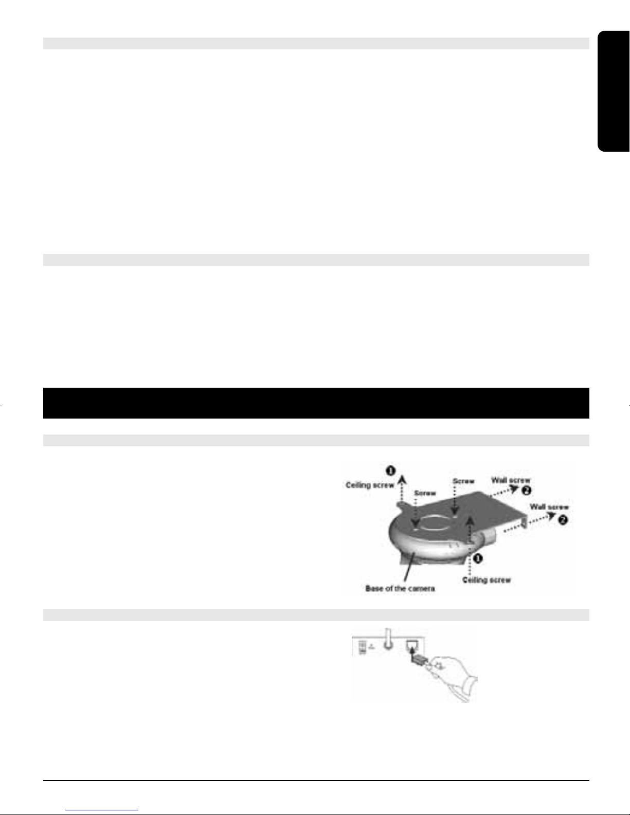
HARDWARE INSTALLATION: ATTACHING THE METAL CLIP
To attach the metal clip, remove the two rubber pads under the
base of the camera firstly. Place the metal clip
onto the camera base, and align the two holes of metal clip
with two screw holes on the base. Secure the
metal clip to the base with two screws (provided). Then, you
can: install the camera to the ceiling using two
ceiling screws (1); or, install the camera to the wall using
two wall screws (2).
CONNECTING THE ETHERNET CABLE
Connect an Ethernet cable to the network cable connector
located on the camera’s rear panel, and then attach it to
the network.
TM
WIRELESS
3IP ROBOCAM8
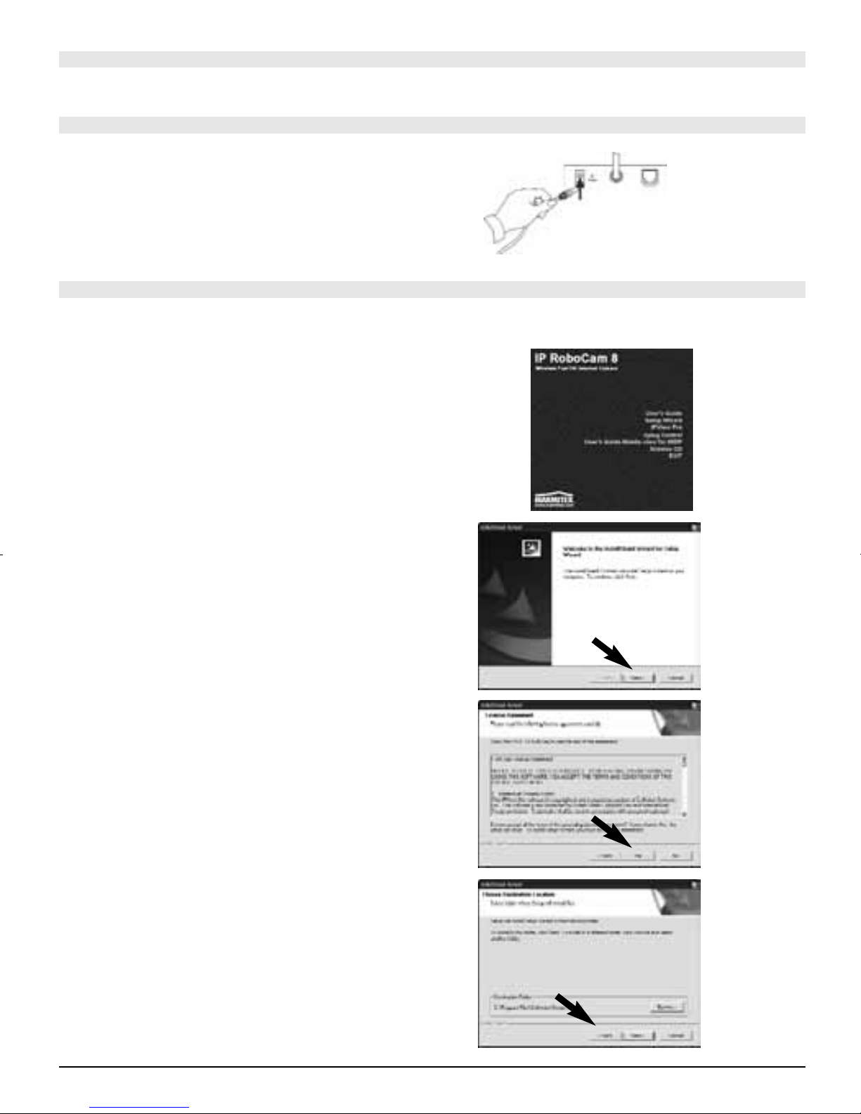
CONNECT THE ANTENNA
Attach the included external antenna to the back of the camera.
CONNECTING THE POWER SUPPLY
Attach the external power supply to the DC power input
connector located on camera’s rear panel, and then connect
it to your local power supply.
TIP: You can check if power is supplied when the
Power LED on the camera is illuminated.
RUNNING THE SETUP WIZARD
The Setup Wizard is a convenient tool that will guide you through the installation of your camera easily and quickly.
After connecting the camera to your computer, you can install the Setup Wizard and complete the configuration
now.
1. Insert the Installation CD-ROM into your CD-ROM drive.
Click Install Wizard.
2. Click Next.
3. Click Yes.
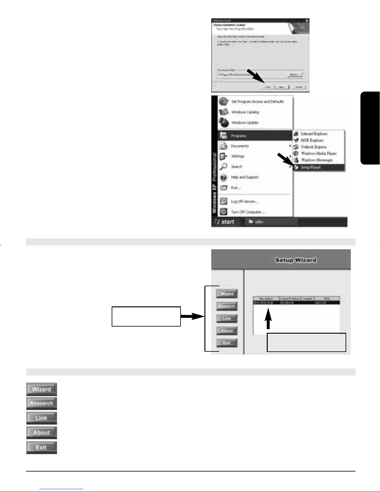
4. Click Next.
4 ® MARMITEK
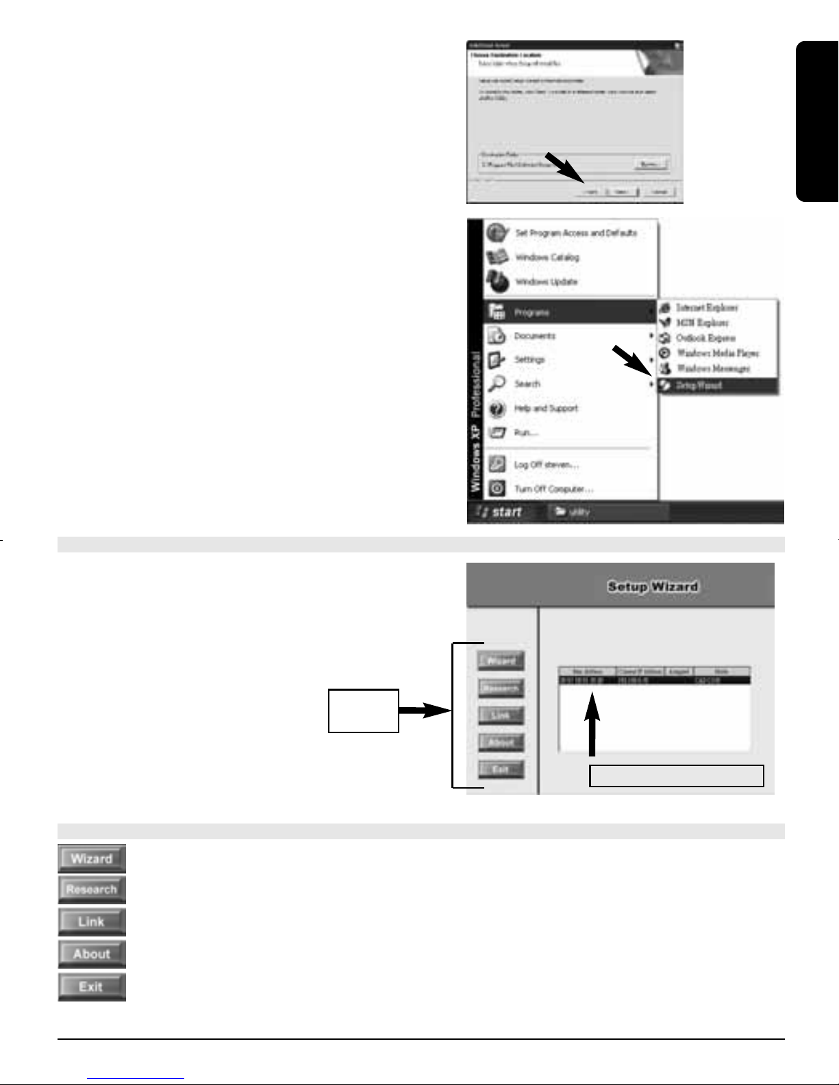
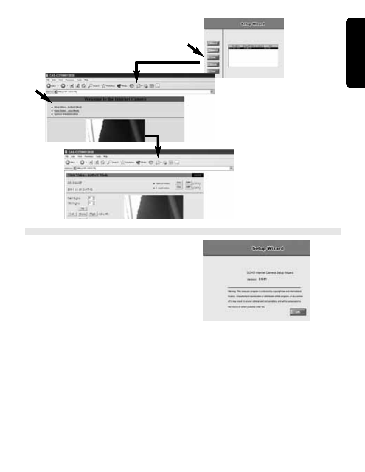
5. Click Finish.
To run the Setup Wizard,
click Start -> Programs -> Setup Wizard.
ENGLISH
USING THE SETUP WIZARD
When you launch the Setup Wizard, the main window will
appear as shown, and the connected camera will be displayed
in the list.
Control
buttons
THE COMPONENTS ON THE SETUP WIZARD
Click Wizard to begin configuring the selected camera.
Click Research to allow you to search the connected camera again.
Click Link to launch the web browser and view the images.
The connected camera list
Click About to show the general information of the selected camera.
Click Exit to close the Setup Wizard.
TM
WIRELESS
5IP ROBOCAM8

CHANGING THE ADMIN ID AND PASSWORD
By default settings, the Admin ID and Password are blank. For security purpose, you are recommended to change
the Admin ID and Password immediately.
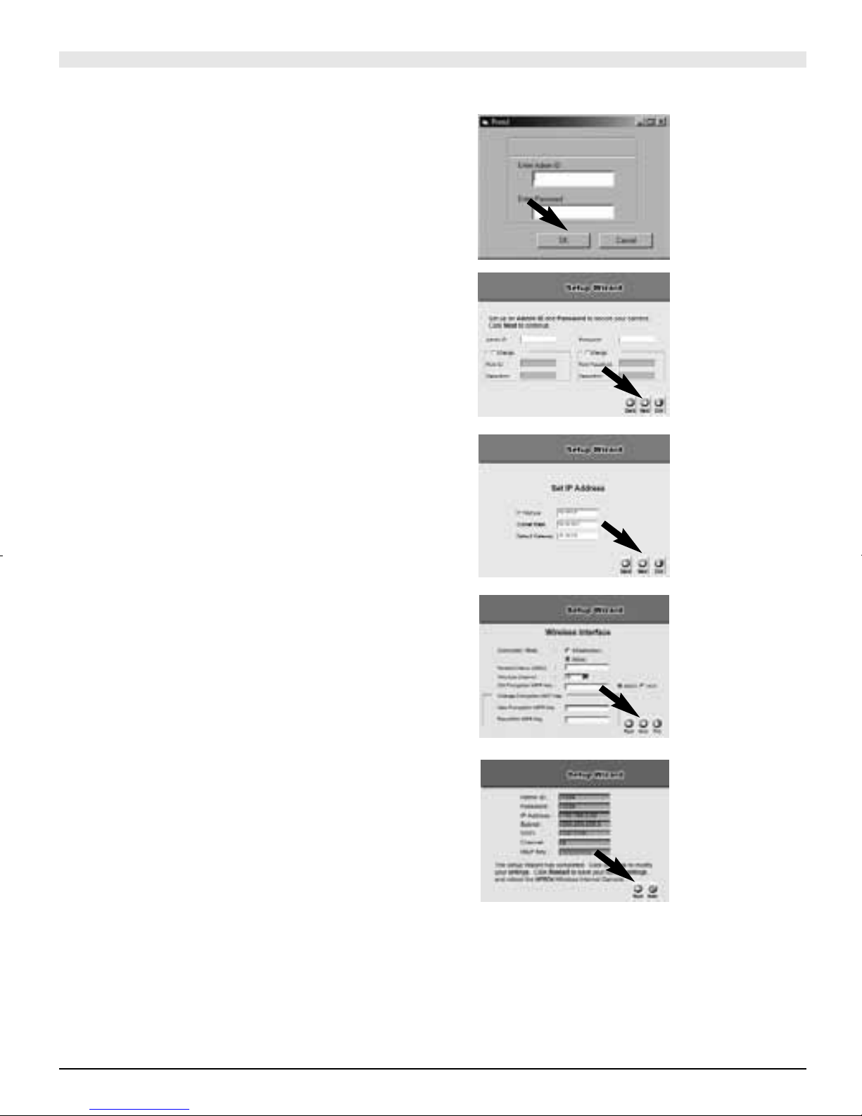
Click Wizard. The dialog box as shown appears,
asking you to enter the Admin ID and Password.
Click OK.
If required, select the Change options and enter
the new Admin ID and Password.
Click Next.
The settings of IP Address, Subnet Mask and
Default Gateway must correspond with your
camera and networking settings.
Please check with your network administrator
for correct settings.
Click Next.
The Connection Mode depends on how your camera is
connected to your network. Click Infrastructure for use with a
router or Adhoc for peer-to- peer. The Network Name, Wireless
Channel, and Encryption Key MUST correspond with your wireless network settings.
This window displays the settings you set up. For any change,
click Back to modify your settings. Otherwise, click Restart
to save and apply the settings.
6 ® MARMITEK
The configuration is completed, and you will return to the main
window. Click Link to launch the web browser and view the
images.
ENGLISH
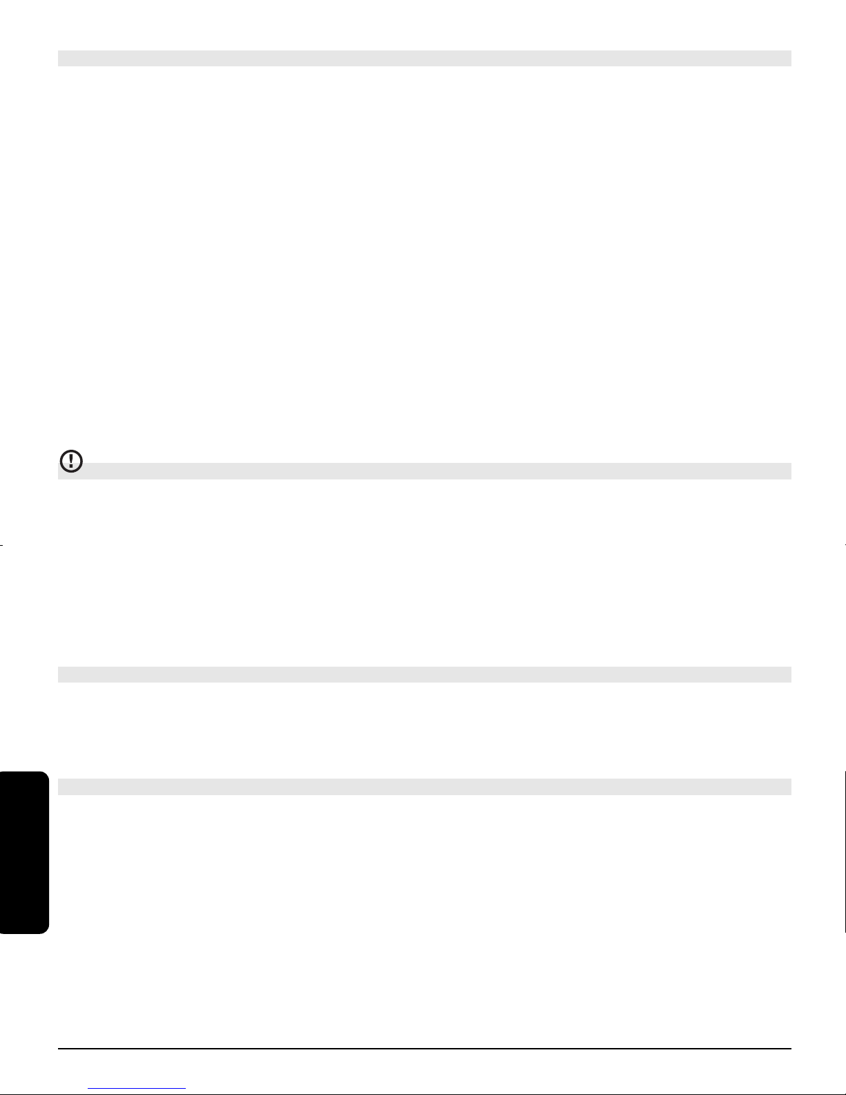
SOFTWARE INFORMATION
Click About to show the general information
of the selected camera.
Click OK to return to the main window.
TM
WIRELESS
7IP ROBOCAM8
TECHNICAL DATA
General
Camera: 1/4" colour CMOS , 640x480 pixels
Lens: f: 6.0mm, F: 1.8
Minimum illumination: 2.5 Lux
Compression: JPEG, 5 levels
Frame rate: Max 30fps
Resolution: 160x120, 320x240, 640x480
Power: 5VDC 2,5A, 230 V power adapter included
Temperature for use: +5° / +40° C
Pan&Tilt: Horizontal -170° ~ +170°, Vertical +45° ~ -90°
Dimensions: 120x120x110mm
Communication:
LAN port: RJ45, 10/100Mb auto-sense, auto MDI-X
WLAN port: 802.11g wireless LAN Range dependent on network.
Protocol: HTTP, FTP, TCP/IP, UDP, ARP, ICMP, BOOTP, RARP, DHCP, PPPoE, DDNS, UPnP
Software:
Web browser: Supporting ActiveX or Java
Application: IP View Pro (16 cameras )
Users: max. 64
ATTENTION
This appliance is designed to be used in all EU and EFTA countries.
Attention: The use of this product may be restricted in the following countries:
• Belgium:
2.4 GHz Frequency. The use of this frequency may be restricted in some areas. See http://www.bipt.be for current
information.
• France:
2.4 GHz Frequency. The use of channels other than: 10, 11, 12, 13 (2457, 2462, 2467, and 2472 MHz) may be
restricted in some areas. See l'Autorité de Régulation des Télécommunications (http://www.art-telecom.fr) for current
information.
TECHNICAL SUPPORT
For more information, please refer to the User’s Guide located on the CD-ROM.information.
SICHERHEITSHINWEISE
• Um Kurzschluss vorzubeugen, dieses Produkt bitte ausschließlich innerhalb des Hauses und nur in trockenen
Räumen nutzen. Setzen Sie die Komponenten nicht Regen oder Feuchtigkeit aus. Nicht neben oder nahe eines
Bades,Schwimmbades usw. verwenden.
• Setzen Sie die Komponente Ihres Systems nicht extrem hohen Temperaturen oder starken Lichtquellen aus.
• Das Produkt niemals öffnen: Das Gerät enthält Bestandteile mit lebensgefährlicher Stromspannung. Überlassen
DEUTSCH
Sie Reparaturen oder Wartung nur Fachleuten.
•
Bei einer zweckwidrigen Verwendung, selbst angebrachten Veränderungen oder selbst ausgeführten Reparaturen
verfallen alle Garantiebestimmungen. Marmitek übernimmt bei einer falschen Verwendung des Produkts oder bei
einer anderen Verwendung des Produktes als für den vorgesehenen Zweck keinerlei Produkthaftung. Marmitek
übernimmt für Folgeschäden keine andere Haftung als die gesetzliche Produkthaftung.
• Netzadapter: Schließen Sie den Netzadapter erst dann an das Stromnetz an, nachdem Sie überprüft haben, ob
die Netzspannung mit dem auf dem Typenschild angegeben Wert übereinstimmt. Schließen Sie niemals einen
Netzadapter oder ein Netzkabel niemals an, wenn diese beschädigt sind. In diesem Fall nehmen Sie Kontakt mit
Ihrem Lieferanten auf.
8 ® MARMITEK

MINDEST-SYSTEMANFORDERUNGEN
Hardware: CD ROM Laufwerk
Operating system: MS Windows 98SE, ME,NT, NT4.0, 2000, XP.
LAN Anschluss: 10 Base-T Ethernet oder 100 Base-TX Fast Ethernet
WLAN Anschluss: 802.11b/g Router/Access Point (und Ethernet Verbindung für die Installation)
Für Kamera-Installierung und Webbrowser Anwender:
Prozessor: Pentium 2 oder mehr
Speicher: 64 MB RAM, 5MB freier Speicherplatz
Web Browser: Unterstützt ActiveX oder Java
Für Installierung und IP View Pro Benutzeranwendung:
Prozessor: Pentium 3 oder mehr
Speicher: 128 MB RAM, 500 / 1000MB freier Speicherplatz
Web Browser: Unterstützt ActiveX oder Java
PACKUNGSINHALT
• Eine dreh- und schwenkbare Internetkamera
• Ein Netzteil
• Ein RJ-45-Ethernetkabel
• Ein externe Antenne
• Ein Metallbügel
• Diese Kurz-Installationsanleitung
• Eine Installations-CD
DEUTSCH
Hinweis: Sollte etwas beschädigt sein oder fehlen, wenden Sie sich bitte sofort an Ihren Händler vor Ort.
Vor Ihnen liegt der Leitfaden in dem beschrieben wird, wie Sie den IP Robocam anschließen können.
Eine umfassende Beschreibung aller Möglichkeiten der Kamera finden Sie in der Gebrauchsanleitung auf der
mitgelieferten CD ROM.
HARDWAREINSTALLATION: METALLBÜGEL ANBRINGEN
Zum Anbringen des Metallbügels müssen Sie zunächst die
beiden Gummipuffer am Boden der Kamera entfernen.
Setzen Sie den Metallbügel so auf den Kameraboden auf, dass
sich die beiden Bohrungen im Bügel über den Schraublöchern
am Kameraboden befinden. Fixieren Sie den Metallbügel mit
den zwei Schrauben (beiliegend) am Kameraboden. Danach
können Sie: Die Kamera mit zwei Deckenschrauben (1) an der
Decke oder mit zwei Wandschrauben (2) an der
Wand befestigen.
ETHERNETKABEL ANSCHLIEßEN
Schließen Sie ein Ethernetkabel an den Anschluss an der
Kamerarückseite an, verbinden Sie das Kabel dann mit Ihrem
Netzwerk.
TM
WIRELESS
9IP ROBOCAM8

DIE ANTENNE ANSCHLIEßEN
Schrauben Sie die mitgelieferte, externe Antenne auf die Rückseite der Kamera.
CONNECTING THE POWER SUPPLY
Verbinden Sie das externe Netzteil mit dem Netzteilanschluss an
der Rückseite der Kamera, schließen Sie das Netzteil dann an
eine Steckdose an.
TIPP: Wenn die LED-Betriebsanzeige der Kamera aufleuchtet,
wissen Sie, dass die Kamera mit Strom versorgt wird.
EINRICHTUNGSASSISTENTEN STARTEN
Der Einrichtungsassistent ist ein praktisches Werkzeug, das Sie schnell und einfach durch die Installation Ihrer Kamera
führt. Nachdem Sie die Kamera an Ihren Computer angeschlossen haben, können Sie den Einrichtungsassistenten
starten und die Konfiguration abschließen.
1. Legen Sie die Installations-CD in Ihr CD-ROM-Laufwerk ein.
Klicken Sie auf Install Wizard (Installationsassistent).
2. Klicken Sie auf Next (Weiter).
3. Klicken Sie auf Yes (Ja).
4. Klicken Sie auf Next (Weiter).
10 ® MARMITEK
5. Klicken Sie auf Finish (Fertigstellen).
Zum Starten des Installationsassistenten klicken Sie
auf Start (Alle) -> Programs -> Setup Wizard.
DEUTSCH
EINRICHTUNGSASSISTENTEN VERWENDEN
Nach dem Starten des Einrichtungsassistenten erscheint das
Hauptfenster (siehe Abbildung), die angeschlossene Kamera
wird in der Liste angezeigt.
Auswahlschaltflächen
Liste mit angeschlossenen
DIE KOMPONENTEN DES EINRICHTUNGSASSISTENTEN
Zum Konfigurieren der ausgewählten Kamera klicken Sie auf Wizard (Assistent).
Durch Anklicken von Research (Erneut suchen) können Sie angeschlossene Kameras neu erkennen lassen.
Klicken Sie auf Link, um Ihren Webbrowser zu starten und sich Bilder darüber anzuschauen.
Kameras
Wenn Sie auf About (Info) klicken, erhalten Sie allgemeine Informationen zur ausgewählten Kamera.
Mit einem Klick auf Exit (Beenden) schließen Sie den Einrichtungsassistenten.
TM
WIRELESS
11IP ROBOCAM8
ADMIN-ID UND KENNWORT ÄNDERN
Per Vorgabe sind Admin-ID und Kennwort nicht ausgefüllt. Aus Sicherheitsgründen empfehlen wir Ihnen, Admin-ID
und Kennwort so schnell wie möglich zu ändern.
Klicken Sie auf Wizard (Assistent). Das nebenstehende
Dialogfenster erscheint und fordert Sie zur Eingabe von
Admin-ID und Kennwort auf.
Klicken Sie auf OK.
Wenn nötig, markieren Sie die Option Change (Ändern) und
geben eine neue Admin-ID und ein neues Kennwort ein.
Klicken Sie auf Next (Weiter).
Die Einstellungen für IP Address (IP-Adresse), Subnet Mask
(Subnetzmaske) und Default Gateway (Standardgateway) müssen
bei Kamera und Netzwerk identisch sein. Bitte fragen Sie Ihren
Netzwerkadministrator nach den richtigen Einstellungen.
Klicken Sie auf Next (Weiter).
Der Connection Mode (Verbindungsmodus) hängt davon ab,
auf welche Weise Ihre Kamera mit dem Netzwerk verbunden
wird. Klicken Sie auf Infrastructure (Infrastruktur), wenn Sie
einen Router einsetzen, wählen Sie Adhoc (Ad-Hoc) bei einer
Direktverbindung („peer-to-peer“). Network Name
(Netzwerkname), Wireless Channel (Funkkanal) und Encryption
Key (Netzwerkschlüssel) müssen mit den Einstellungen Ihres
Drahtlosnetzwerkes übereinstimmen.
In diesem Fenster werden die von Ihnen vorgenommenen
Einstellungen angezeigt. Falls Sie diese ändern möchten,
klicken Sie auf Back (Zurück). Ansonsten klicken Sie auf Restart
(Anwenden), um die Einstellungen zu speichern und in Kraft
treten zu lassen.
12 ® MARMITEK
 Loading...