

Page 1
Service
OFFON
POWER
VOLUME LEVEL
HIGH CUT
MAXMIN
POWER ON
150Hz
50Hz
/STANDBY
ACTIVE SUBWOOFER SW200
SW200/F1M, /K1M
Manual
Active Subwoofer
TABLE OF CONTENTS
1. TECHNICAL SPECIFICATIONS .............................................................................1
2. BLOCK DIAGRAM ..................................................................................................2
3. WIRING DIAGRAM.................................................................................................3
4. SCHEMATIC DIAGRAM AND PARTS LOCATION .................................................5
5. EXPLODED VIEW AND PARTS LIST...................................................................11
6. ELECTRICAL PARTS LIST...................................................................................13
Please use this service manual with referring to the user guide (D.F.U) without fail.
Printed in Japan
SW200
SW200
317W855010 AO
First Issue:2001.07
Page 2
MARANTZ DESIGN AND SERVICE
Using superior design and selected high grade components, MARANTZ company has created the ultimate in stereo sound.
Only original
it is famous.
Parts for your
ORDERING PARTS :
Parts can be ordered either by mail or by Fax.. In both cases, the correct part number has to be specified.
The following information must be supplied to eliminate delays in processing your order :
1. Complete address
2. Complete part numbers and quantities required
3. Description of parts
4. Model number for which part is required
5. Way of shipment
6. Signature : any order form or Fax. must be signed, otherwise such part order will be considered as null and void.
MARANTZ parts can insure that your MARANTZ product will continue to perform to the specifications for which
MARANTZ equipment are generally available to our National Marantz Subsidiary or Agent.
USAUSA
MARANTZ AMERICA, INCMARANTZ AMERICA, INC.
1100 MAPLEWOOD DRIVE
ITASCA, IL. 60143
USA
PHONE : 630 - 741 - 0300
FAX : 630 - 741 - 0301
AMERICAS AMERICAS
SUPERSCOPE TECHNOLOGIES, INC.SUPERSCOPE TECHNOLOGIES, INC.
MARANTZ PROFESSIONAL PRODUCTS
2640 WHITE OAK CIRCLE, SUITE A
AURORA, ILLINOIS 60504 USA
PHONE : 630 - 820 - 4800
FAX : 630 - 820 - 8103
AUSTRALIAAUSTRALIA
QualiFi Pty Ltd,QualiFi Pty Ltd,
24 LIONEL ROAD,
MT. WAVERLEY VIC 3149
AUSTRALIA
PHONE : +61 - (0)3 - 9543 - 1522
FAX : +61 - (0)3 - 9543 - 3677
NEW ZEALANDNEW ZEALAND
WILDASH AUDIO SYSTEMS NZWILDASH AUDIO SYSTEMS NZ
14 MALVERN ROAD MT ALBERT
AUCKLAND NEW ZEALAND
PHONE : +64 - 9 - 8451958
FAX : +64 - 9 - 8463554
EUROPE / TRADING EUROPE / TRADING
MARANTZ EUROPE B.V.MARANTZ EUROPE B.V.
P.O.BOX 80002, BUILDING SFF2
5600 JB EINDHOVEN
THE NETHERLANDS
PHONE : +31 - 40 - 2732241
FAX : +31 - 40 - 2735578
AUSTRALIA AUSTRALIA
TECHNICAL AUDIO GROUP PTY, LTDTECHNICAL AUDIO GROUP PTY, LTD
558 DARLING STREET,
BALMAIN, NSW 2041,
AUSTRALIA
PHONE : 61 - 2 - 9810 - 5300
FAX : 61 - 2 - 9810 - 5355
THAILANDTHAILAND
MRZ STANDARD CO.,LTDMRZ STANDARD CO.,LTD
746 - 754 MAHACHAI ROAD.,
WANGBURAPAPIROM, PHRANAKORN,
BANGKOK, 10200 THAILAND
PHONE : +66 - 2 - 222 9181
FAX : +66 - 2 - 224 6795
TAIWANTAIWAN
PAI- YUING CO., LTD.PAI- YUING CO., LTD.
6 TH FL NO, 148 SUNG KIANG ROAD,
TAIPEI, 10429, TAIWAN R.O.C.
PHONE : +886 - 2 - 25221304
FAX : +886 - 2 - 25630415
BRAZILBRAZIL
PHILIPS DA AMAZONIA IND. ELET. ITDAPHILIPS DA AMAZONIA IND. ELET. ITDA
CENTRO DE INFORMACOES AO
CEP 04698-970
SAO PAULO, SP, BRAZIL
PHONE : 0800 - 123123
FAX : +55 11 534. 8988
(Discagem Direta Gratuita)
CANADACANADA
LENBROOK INDUSTRIES LIMITEDLENBROOK INDUSTRIES LIMITED
633 GRANITE COURT,
PICKERING, ONTARIO L1W 3K1
CANADA
PHONE : 905 - 831 - 6333
FAX : 905 - 831 - 6936
SINGAPORESINGAPORE
WO KEE HONG DISTRIBUTION PTE LTDWO KEE HONG DISTRIBUTION PTE LTD
130 JOO SENG ROAD
#03-02 OLIVINE BUILDING
SINGAPORE 368357
PHONE : +65 858 5535 / +65 381 8621
FAX : +65 858 6078
MALAYSIAMALAYSIA
WO KEE HONG ELECTRONICS SDN. BHD.WO KEE HONG ELECTRONICS SDN. BHD.
SUITE 8.1, LEVEL 8, MENARA GENESIS,
NO. 33, JALAN SULTAN ISMAIL,
50250 KUALA LUMPUR, MALAYSIA
PHONE : +60 3 - 2457677
FAX : +60 3 - 2458180
JAPANJAPAN
MARANTZ JAPAN, INC.MARANTZ JAPAN, INC.
Technical
35- 1, 7- CHOME, SAGAMIONO
SAGAMIHARA - SHI, KANAGAWA
JAPAN 228-8505
PHONE : +81 42 748 1013
FAX : +81 42 741 9190
KOREAKOREA
MK ENTERPRISES LTD.MK ENTERPRISES LTD.
ROOM 604/605, ELECTRO-OFFICETEL, 16-58,
3GA, HANGANG-RO, YONGSAN-KU, SEOUL
KOREA
PHONE : +822 - 3232 - 155
FAX : +822 - 3232 - 154
SHOCK, FIRE HAZARD SERVICE TEST :
CAUTION : After servicing this appliance and prior to returning to customer, measure the resistance between either primary AC
cord connector pins ( with unit NOT connected to AC mains and its Power switch ON ), and the face or Front Panel of product and
controls and chassis bottom.
Any resistance measurement less than 1 Megohms should cause unit to be repaired or corrected before AC power is applied, and
verified before it is return to the user/customer.
Ref. UL Standard No. 1492.
In case of difficulties, do not hesitate to contact the Technical
Department at above mentioned address.
010620 A.O
Page 3

1.TECHNICAL SPECIFICATIONS
AMPLIFIER
Output................................................................................................................................................................................... 70 W (EIAJ THD 10%)
Input Terminals ........................................................................................................................................................................................Line / SPK.
Output Terminals................................................................................................................................................................................................SPK.
S/N Ratio .......................................................................................................................................................................................................... 95 dB
SPEAKER
Type......................................................................................................................................................................................... 1-way Bass Ref type
Playback Frequency Response .............................................................................................................................................. 30 ~ 200 Hz (–10 dB)
Drive Unit................................................................................................................................. Magnetically shielded woofer with 200mm cone x 1
High Cut Filter ............................................................................................................................ 50 ~ 150 Hz Continuously variable (–24 dB / oct.)
POWER SUPPLY
Power Supply.................................................................................................................................................................. AC 100V, 50 / 60 Hz ( /F )
Rated power consumption ................................................................................................................................................................................ 39 W
APPEARANCE
Maximum External Dimensions......................................................................................................235 x 340 x 318 mm (Width x Height x Depth)
Weight ..............................................................................................................................................................................................................8.4 kg
ACCESSORIES
Audio Cable (3m - RCA Pin plug)............................................................................................................................................................................ 1
Speaker Cable (4 m) ................................................................................................................................................................................................2
User's Manual ...................................................................................................................................................................................................... 1
AC 110 - 115V/ 220 - 230V, 50 / 60 Hz ( /K )
* The SW200 drive unit has a magnetically shielded design, but it may cause color irregularities on television screens if place
In this case, increase the distance between the television and the SW200 unit accordingly.
* Specifications and appearance are subject to change without notice due to improvements.
d close to the set.
1
Page 4
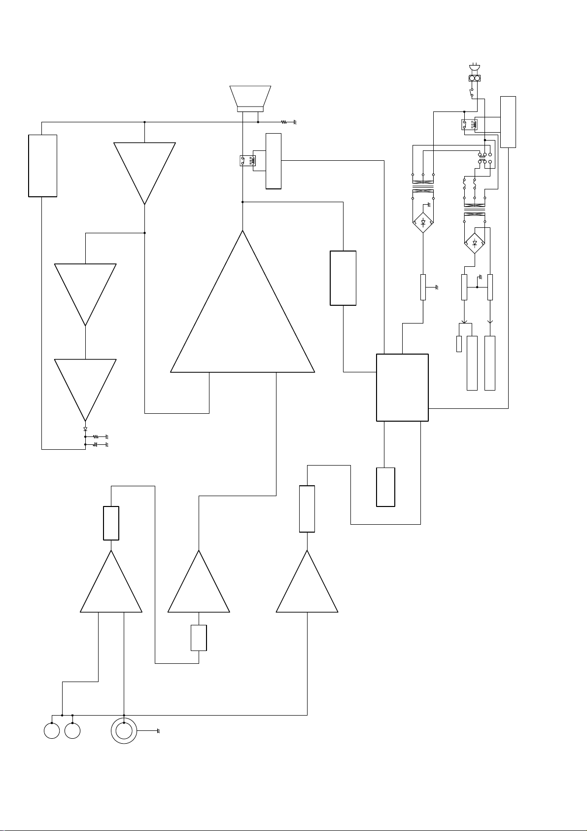
2. BLOCK DIAGRAM
FET
Q304
IC307IC308
IC306
WOOFER UNIT
RY301
R318
Q303 C3198
OUTPUT RELAY CONTROL
Q301/302
DC PROTECTOR
T501
D501
0V
IC303 78S05
SW601
RY501
F502
T301
D305
IC304 7815
1
SW701
2
456
123
F501
PN502
0V
IC305 7915
Q501 C3198
POWER RELAY CONTROL
D304
R339
C320
MAIN VOLUME
VR201
IC101
IC201
STK4036
POWER AMP.
IC302
Q101
SIGNAL PROTECTOR
IC102
IC301
MICOM
LED201
LED(RED/GREEN)
+5V
+15V
RY301
OP AMP.
IC101,201,306,307,308
-15V
OP AMP.
IC101,201,306,307,308
SPEAKER TERMINAL
JK101
RCA JACK
JK102
VR202
HI-CUT VR
LPF/HPF
2
Page 5

3. WIRING DIAGRAM
JACK PWB
CN101
MAIN PWB
JK101
PN302
JK102
SW101
SECONDARY
MAIN TRANSFORMER
VR PWB
VR201
CN201
VR202
TO.SPK UNIT
PN101
PN301
PN201
IC302
F ONLY
PN502
F ONLY
AC100V AC200V
PN503 PN504
T501
PN501-1 PN501-2 PN501-3
PN701-3 PN701-2 PN701-1
PRIMARY
K ONLY
PN702
POWER SWITCH PWB
SW601
PN601
MAINS CORD
SW701
VOLTAGE SELECTOR PCB
K ONLY
3 4
Page 6

4. SCHEMATIC DIAGRAM AND PARTS LOCATION
JK101
(L)
(L)
(R)
(R)
(L)
2
PN701-1PN701-2
JW-6018B
C115
R101
3.9K
C116C117C118
R108
3.9K
L
JK102
R
31231
PN702
R102
100K
0.01(C)
R104
2.7M
R105
100K
2.2K
R103
0.01(C)0.01(C)0.01(C)
R106
100K
2.2K
R107
R109
2.7M
R110
100K
R113
12K
100K100K
R111R112
R114
12K
K ONLY
TO POWER SWITCH
R131
1K
C101
220P(C)
R132
1K
JACK PCB PART
4558
3
2
3.3K
R115
4558
5
+
6
-
C105
0.01(M)
HIGH(2-4)
LOW(2-3)
OFF(1-2)
8
IC101
R121
47K
AUTO STANDBY
C324
220/16
C325
220/16
C104
10/50
R120
470K
C114
0.047(C)
5
HIGH
LEVEL INPUT
EXTERNAL
SPEAKER OUTPUT
HIGH
LEVEL INPUT
EXTERNAL
SPEAKER OUTPUT
HIGH
LEVEL INPUT
EXTERNAL
SPEAKER OUTPUT
HIGH
LEVEL INPUT
EXTERNAL
SPEAKER OUTPUT
LOW LEVEL INPUT
RCA JACK
VOLTAGE SELECTOR PART
SW701
AC220V AC100V
312
PN701-3
CAUTION
Safety precaution to be followed during servicing
1]Since those parts marking with critical parts
for safety.
Use only the one described in the parts list.
2]Before returning the set to the customer make
appropriate leakage current or resistance
measurements to determine the exposed parts are
properly insulated from the supply circuit.
OPTION LIST
1.OJ200,OJ201,PN504,F502:ONLY AC220V
2.OJ100,PN503,F501:ONLY AC100V
NOTES
1.Resistor values are indicated in ohms
unless otherwise specified
2.Capacitor values are indicated in microfarades
unless otherwise specified
3.
:These resistors are to be segregated from
printed wiring board or other accessible parts.
4.(M)is polyester film capacitor or
metallized polyester film capacitor.
(R)
654
321
312
[k=1,000 M=1,000,000]
[p=micro-micro farades]
+
4
IC101
1
R116
3.3K
C102
220P(C)
4.7K
R117
C106
10/25
7
C107
47/16
C108
10/50
SW101
4
8
3
7
2156
470
R306
ERROR
LED RD
GP2 GP1 GP0 Vss
GP3
4321
R301
P-SENS
SIGNAL
R302
10K
0.1(C)
C337
1
OI
-15V
R118
R119
100k(1/4W)
100K
C110
4558
+
3
4
IC102
2
47K
C111
10/50
4558
47K
5
+
8
IC102
6
-
R125
56K
10/50
100
R124
470
R123
R122
C103
10/25
R129
MAIN PCB PART
470
R307
PIC12C508A-04/P
C338
0.1(C)
C301
220/16
ZD302
1N4735
ZD303
1N4735
C339
0.1(C)
SUB P/T GND AMP IC GND
IC301
10K
IC304
7815
7915
IC305
RELAY-O
RELAY-P
2
3
VddGP5GP4
LED GN
3
IO
21
8765
C326
10/50
C327
10/50
1
7
R303
10K
C112
R130
47/16
R126
3.3K
6.2V 1W6.2V 1W
ZD301
1N4735
ZD304
1N4735
6.2V 1W6.2V 1W
47
10/50
D102
1N4148
C113
D101
1N4148
Q301
C3198
R304
100K
KIA78S05P
IC303
1
OI
2
C328
4700/50
C329
4700/50
C340
0.047(C)
C109
Q306
IC302 : STK4036
VR PCB PART
C201
`3`2`1
VR202
10KC
MAIN SIG.IN
MAIN SIG.OUT
+15V
GND
7456312
7456312
Q308
C3198
470
R356
0.68(M)
R203
3.3K
-15V
Q307
A1266
R308
1K
100/10
C3198
R127
Q302
C302
1K
R305
68k
47/50
CN101
PN101
R354
R355
470
C3198
100K
R128
C3198
MAIN SIG.
456
312
456
312
47/16
R202
321
3.3K
3
1
-15V
VR202
10KC
2
CN201
GND
+15V
PN201
C322
C321
100/16
100/16
R201
100
VR201
5KA
Q101
47K
SIGNAL
+5V
C336
3
C333
10/50
R342 R340
18K(1/4W)
18K(1/4W)
R341
18K(1/4W)
R343
18K(1/4W)
PBS404GU
D305
C330
0.047(M)
C331
0.047(M)
PN302
1
2
3
C202
LED201
LED RD
LED GN
10
R357
C323
0.47(M)
MAIN TRANSFORMER
0.18(M)
REDGN
ZD501
4558
2
-
3
+
SAM3270
7
Q305
A1266
T301
IC201
C502
10/50
5.1V
8
IC308
R309
3.3K
R204
-
4558
6
18K
IC201
1
4
R501
0V
C205
5
+
6
-
100/16
C303
10K
C320
10/50
100K
R353
1
2
3
1
2
3
10/50
C203 C204
0.15(M) 0.15(M)
D304
1N4148
220K
R339
47/16
100
R310
C335
C305
0.01(M)
C304
R502
4.7K
C503
1000/25
PN503
PN504
222(C)
R505
10K
45584558
C306
100/50
1
6
8
2
R312
1N4148
R503
4
1
IC308
R338
22K
3
15
STK4036
IC302
5
4
10K
R313
100(1/4W)
D502
R504
2.2(1/4W)
3.3k
F502
F501
Q501
7
8
+-
5
56K
R205
C206
10/50
5
4558
+
8
7
C311
100/50
C310
1N4148
R337
C307
100P(C)
7
C313
10
R314
100K
KBPM06G
D501
D303
8.2K
14
12
1/50
C334
0.01(M)
OTHERS
OTHERS
IC307
1N4148
1N4148
C308
13
C312
100P(C)
-
D302
1N4148
R336
8.2K
D306
D307
10/50
C314
F502
T1.0AL 250V
F501
T2.0AL 250V
SB 2.0A 250VJAPAN
6
10/50
8.2K
R350 R351
C504
0.01(M)
C505
0.01(M)
R333
8.2K
R334R335
8.2K
R352
68(1/4W)
1K(1/4W) 1K(1/4W)
STAND BY TRANSFORMER
T501
3
+
2
-
R311
100(1/4W)
11
9
102(C)
C309
0.0039(M)
1.0A/250V 0.0047/250V
2.0A/250V
C3198
4558
3
+
4
1
IC307
2
-
R332
10k
1k
R329
R331
R322
100k
C317
0.47(M)
R316
DG12D1(12VDC)
68(1/4)
D301
1N4148
Q303
R315
10K
0V
OJ100
R330
3.9k
C3198
PN501-3
6.8k
R328
1N4148
D503
10k
RY301
312
OJ200
R327
R317
RY501
4558
C315
9.1K
4558
C506
7
1
OJ201
Q304
2SK315F
150K
R325
D
G
C319
0.1(M)
5
6
C318
100P(C)
3
2
R323
R320
R319
6.8k
R318
S
1M
9.1K
PN301
0.1(5W)
4.7(1W)
0.1(M)
8
IC306
R326
56k
4
IC306
R321
6.8k
C316
220P(C)
R324
100k
+
-
+
-
POWER SWITCH PART
SW601
P-SWITCH
C601
0.0047/250V
PN601
312
PN501-2
312
PN501-1
2
P-CORD
1
312
DG12D1(12VDC)
GP5/OSC1/CLKIN
GP4/OSC2/CLKOUT
GP3/MCLR
/V
1
2
PN502
IC301 : PIC12C508A
PIC12C5XXA
PIC12CE5XXA
DD
V
PP
1
2
3
4
PIC12C5XX
8
7
6
5
V
SS
GP0
GP1
GP2/T0CKI
6
Page 7

(PARTS SIDE)
IC201
VR PCB
POWER SWITCH PCB VOLTAGE SELECTOR PCB
K ONLY
MAIN PCB
Q308
Q501
Q305
Q307
Q304
Q306
Q101
IC102
JACK PCB
IC306
IC307
IC304
IC308
IC302
IC301
IC303
Q301~Q303
IC305
IC101
7
8
Page 8

(SOLDER SIDE)
Q501
Q308
Q306
Q305
Q307
Q304
MAIN PCB
K ONLY
POWER SWITCH PCBVOLTAGE SELECTOR PCB
VR PCB
IC201
IC306
IC307
IC304
IC308
IC302
IC301
IC303
Q301~Q303
IC305
JACK PCB
Q101
IC102
9 10
IC101
Page 9

5. EXPLODED VIEW AND PARTS LIST
16
26
2
15 x3
4
28
12
3
1
20 x4
VERS.
POS.
COLOR
NO
17 x3
20 x12
6
1 3720V-0008A FRONT PANEL 317W248010
2 4940V-0008A BUTTON POWER 317W270010
3 4940V-0009A KNOB VOLUME/HIGH CUT 317W154010
4 3300V-0001A SHIELD nsp
DESCRIPTION
PART NO.
(MJI)
5 /F 3720V-0009A REAR PANEL nsp
5 /K 3720V-0009B REAR PANEL nsp
9
23
25
F ONLY
34
15 x15
21
6 3550V-0002A COVER JACK PCB nsp
7 4930V-0007A HOLDER PCB nsp
8 4930V-0006A CORD BUSHING 317W259010
9 4850V-0001F CUSHION nsp
10 SGC-223-01 NET GRILL ASSY 317W401500
11 SPB-000-03 BADGE MARANTZ.AU(GOLD) 354H251230
12 SUE-551-04 DUCT nsp
13 SXB-200-59 WOOFER UNIT QK0205901R
14 HAB-232-05 BODY nsp
15 4000V-0001F SCREW nsp
31 x6
22
19 x2
K ONLY
18 x4
8
35
16 4000V-0007A SCREW nsp
7
5
17 4000V-0001K SCREW nsp
18 4000V-0002A SCREW nsp
19 4000V-0001D SCREW(BIND HEAD) nsp
20 SFG-000-05 SCREW WOOD nsp
15 x3
21 SRB-002-02 LABEL SERIAL NO. nsp
22 4920V-E007A HEATSINK MAIN nsp
30
K ONLY
27
24
23 /K 6410V-E1W0A POWER CORD *ZC000120R
23 /F 6410V-J0W0A POWER CORD *ZC000130R
24 /K 6170V-Z66WK POWER TRANSFORMER *TS001390R
24 /F 6170V-J66WK POWER TRANSFORMER *TS001400R
25 6630V-WTBCT SPEAKER CONNECTOR 2P nsp
26 6630V-WWBDT CONNECTOR 2P nsp
29
27 6630V-WWCKD CONNECTOR 5P nsp
28 SGG-881-01 GASKET PORT nsp
29 SGG-270-01 GASKET EVA nsp
30 SGG-050-01 GASKET CORD nsp
31 SFG-000-20 SCREW nsp
32 YMG-500 COLOR TIE 100mm nsp
33 SGG-187-03 WOOFER GASKET nsp
32
34 4850V-0001D CUSHION nsp
35 4850V-0001E CUSHION nsp
14
33
13
001T /F USER GUIDE JAPANESE 317W851110
001T /K USER GUIDE
PACKING
317W851350
ENGLISH/CHINESE
REMARK
10
11
NOT STANDARD SPARE
PARTS
001S PACKING CASE 317W801010
002S CUSHION 317W809010
REMARK
- NET GRILL ASS'Y (Pos. No. 10) and BODY (Pos. No. 14) can be fixed by bond.
- If NET GRILL ASS' Y (Pos . No . 10 ) r em ov es f r om B ODY (Pos . No. 14 ), it w ill b e loos e an d w ill b ec o me
easy t o se p arat e . In th at case, pl ease f i x by b ond or et c . and c o rresp ond .
- If WOOFER UNIT (Pos . No. 13 ) r em ov es f ro m B ODY (Pos . No . 14 ), SCREW (Pos . No . 20) will be l o o se
and w ill no t b e affec t i v e. In that c as e, p leas e fi x by bon d or et c . and c o rrespon d .
11 12
NOTE : "nsp" PART IS LISTED FOR REFERENCE ONLY, MARANTZ WILL NOT SUPPLY THESE PARTS.
Page 10

6. ELECTRICAL PARTS LIST
MAIN CIRCUIT BOARD
CAPACITORS
C301 0CE2276F605 ELECT 220/16,TP nsp
0CE4766K605 ELECT 47/50,TP nsp
0CE1076F605 ELECT 100/16,TP ns p
0CK2220K405 CER. 222,TP nsp
0CQ1031N405 MYLAR 103,TP nsp
0CE1076K605 ELECT 100/50,TP nsp
0CC1010K415 CER. 100P,TP nsp
0CE1066K605 ELECT 10/50,TP nsp
0CE1076K605 ELECT 100/50,TP nsp
0CQ3921N405 MYLAR 392,TP nsp
0CK1020K405 CER. 102,TP nsp
0CC1010K415 CER. 100P,TP nsp
0CE1056K605 ELECT 1/50,TP nsp
0CE1066K605 ELECT 10/50,TP nsp
0CQ1041N405 MYLAR 104,TP nsp
0CC2210K405 CER. 220P nsp
0CQ4741N401 MYLAR 474 nsp
0CC1010K415 CER. 100P,TP nsp
0CQ1041N405 MYLAR 104,TP nsp
0CE1066K605 ELECT 10/50,TP nsp
0CE1076F605 ELECT 100/16,TP nsp
0CE1076F605 ELECT 100/16,TP nsp
0CQ4741N401 MYLAR 474 nsp
0CE2276F605 ELECT 220/16,TP
0CE2276F605 ELECT 220/16,TP
0CE1066K605 ELECT 10/50,TP
0CE1066K605 ELECT 10/50,TP
0CE4787K610 ELECT 4700/50
0CE4787K610 ELECT 4700/50
0CQ4731N405 MYLAR 473,TP nsp
0CQ4731N405 MYLAR 473,TP nsp
0CE1066K605 ELECT 10/50,TP nsp
0CQ1031N405 MYLAR 103,TP nsp
0CE4766F605 ELECT 47/16,TP nsp
0CE4766F605 ELECT 47/16,TP nsp
0CK1040K405 CER. 104,TP nsp
0CE1056K605 ELECT 1/50,TP nsp
0CK1040K405 CER. 104,TP nsp
0CK4730K405 CER. 473,TP nsp
0CE1066K605 ELECT 10/50,TP nsp
0CE1086H605 ELECT 1000/25 nsp
0CQ1031N405 MYLAR 103,TP nsp
0CQ1031N405 MYLAR 103,TP nsp
0DC4721R6A1 CER. 472/250V
RESISTORS
0RD1002F409 10K,1/6W,5%,TP52 nsp
0RD1002F409 10K,1/6W,5%,TP52 nsp
0RD1002F409 10K,1/6W,5%,TP52 nsp
0RD1003F409 100K,1/6W,5%,TP52 nsp
0RD6802F409 68K,1/6W,5%,TP52 nsp
0RD4700F409 470,1/6W,5%,TP52 nsp
0RD4700F409 470,1/6W,5%,TP52 nsp
0RD1001F409 1K,1/6W,5%,TP52 nsp
0RD3301F409 3.3K,1/6W,5%, TP52 nsp
0RD1000F409 100,1/6W,5%,TP52 nsp
0RD1000G409 100,1/4W,5%,TP52 nsp
0RD1002F409 10K,1/6W,5%,TP52 nsp
0RD1000G409 100,1/4W,5%,TP52 nsp
0RD1003F409 100K,1/6W,5%,TP52 nsp
0RD1002F409 10K,1/6W,5%,TP52 nsp
0RD0682G409 68,1/4W,5%,TP52 nsp
0RN0471J410 4.7(1W)
0RC0100M425 CEMENT 0.1(5W),
FORMING(25mm)
0RD9101F409 9.1K,1/6W,5%, TP52 nsp
0RD6801F409 6.8K,1/6W,5%, TP52 nsp
0RD6801F409 6.8K,1/6W,5%, TP52 nsp
0RD1003F409 100K,1/6W,5%,TP52 nsp
0RD1004F409 1M,1/6W,5%,TP52 nsp
0RD1003F409 100K,1/6W,5%,TP52 nsp
0RD1503F409 150K,1/6W,5%,TP52 nsp
0RD5602F409 56K,1/6W,5%,TP52 nsp
0RD9101F409 9.1K,1/6W,5%, TP52 nsp
0RD1002F409 10K,1/6W,5%,TP52 nsp
0RD3901F409 3.9K,1/6W,5%, TP52 nsp
0RD6801F409 6.8K,1/6W,5%, TP52 nsp
0RD1001F409 1K,1/6W,5%,TP52 nsp
0RD1002F409 10K,1/6W,5%,TP52 nsp
0RD8201F409 8.2K,1/6W,5%, TP52 nsp
0RD8201F409 8.2K,1/6W,5%, TP52 nsp
0RD8201F409 8.2K,1/6W,5%, TP52 nsp
0RD8201F409 8.2K,1/6W,5%, TP52 nsp
0RD8201F409 8.2K,1/6W,5%, TP52 nsp
0RD2202F409 22K,1/6W,5%,TP52 nsp
0RD2203F409 220K,1/6W,5%,TP52 nsp
0RD1802G409 18K,1/4W,5%,TP52 nsp
0RD1802G409 18K,1/4W,5%,TP52 nsp
0RD1802G409 18K,1/4W,5%,TP52 nsp
0RD1802G409 18K,1/4W,5%,TP52 nsp
0RD1001G409 1K,1/4W,5%,TP52 nsp
0RD1001G409 1K,1/4W,5%,TP52 nsp
0RD0682G409 68,1/4W,5%,TP52 nsp
0RD1003F409 100K,1/6W,5%,TP52 nsp
0RD1003F409 100K,1/6W,5%,TP52 nsp
0RD4700F409 470,1/6W,5%,TP52 nsp
0RD4700F409 470,1/6W,5%,TP52 nsp
0RD0102F409 10,1/6W,5%,TP52 nsp
0RD1002F409 10K,1/6W,5%,TP52 nsp
0RD4701F409 4.7K,1/6W,5%, TP52 nsp
0RD3301F409 3.3K,1/6W,5%, TP52 nsp
0RD0221G409 2.2,1/4W,5%,TP52 nsp
0RD1002F409 10K,1/6W,5%,TP52 nsp
6920V-DG1A1 RELAY DG12D1(12VDC) LY10120350
6920V-DG1A1 RELAY DG12D1(12VDC) LY10120350
SEMICONDUCTORS
0DD4148B052 DIODE 1N4148 nsp
0DD404GE108 DIODE PBS404GU
0DD4148B052 DIODE 1N4148 nsp
0DD4148B052 DIODE 1N4148 nsp
DIODE KBPM06G
0DD4148B052 DIODE 1N4148 nsp
0DD4148B052 DIODE 1N4148 nsp
0IMI508ADIP IC PIC12C508A-04/P
0ISA4036TFH IC STK4036
0IKE78S05TP IC KIA78S05P
0IKE7815SIP IC KIA7815
0IKE7915SIP IC KIA7915
0IKE4558DIP IC KIA4558
0IKE4558DIP IC KIA4558
0IKE4558DIP IC KIA4558
TRS. 2SC3198 nsp
TRS. 2SC3198 nsp
TRS. 2SC3198 nsp
0TF315FBLNC FET,2SK315F
0TR1266AFPN TRS. 2SA1266Y nsp
TRS. 2SC3198 nsp
0TR1266AFPN TRS. 2SA1266Y nsp
TRS. 2SC3198 nsp
NOTE : "nsp" PART IS LISTED FOR REFERENCE ONLY, MARANTZ WILL NOT SUPPLY THESE PARTS.
ASSIGNMENT OF COMMON PARTS CODES.
RESISTORS
R 1) GD05 x x x 140, Carbon film fixed resistor, 5% 1/4W
R 2) GD05 x x x 160, Carbon film fixed resistor, 5% 1/6W
CAPACITORS
C : CERAMIC CAP.
Examples
C : CERAMIC CAP.
Examples
C : 5) ELECTROLY CAP.( ), 6)FILM CAP ( )
Examples
Examples
:
:
Examples
1 Resistance value
0.1 ..... 001 10 ......100 1k ......102 100k ......104
0.5 ..... 005 18 ......180 2.7k ......272 680k ......684
1 ..... 010 100 ......101 10k ......103 1M ...... 105
6.8 ..... 068 390 ......391 22k ......223 4.7M ...... 475
Note : Please distinguish 1/4W from 1/6W by the shape of parts
2 Tolerance (Capacity deviation)
Tolerance of COMMON PARTS handled here are as follows :
3 Capacity value
4 Capacity value
100 pF .....101 1000 pF .... 102 10000 pF .... 103
470 pF .....471 2200 pF .... 222
5 Capacity value
6 Working voltage
7 Capacity value
0.0018
NOTE
used actually.
3) DD1 x x x x 370, Ceramic capacitor
2 Tolerance
0.25 pF ....... 0
0.5 pF ....... 1
5 % .......5
0.5 pF - 5 pF....... 0.25 pF
6 pF - 10 p F ..... 0.5 pF
12 pF - 560 pF ... 5 %
0.5 pF .... 0 0 5 3 p F ..... 0 3 0 100 pF.....101
1 pF .... 01 0 10 p F ..... 1 0 0 220 pF.....221
1.5 pF .... 0 1 5 47 p F ..... 4 7 0 560 pF.....561
4) DK16 x x x 300, High dielectric constant ceramic
5) EA x x x x x x 10, Electrolytic capacitor
0.1 F .... 104 4. 7 F .... 475 1 0 0 F .....107
0.33 F .... 3 3 4 10 F .... 106 330 F ..... 337
1 F .... 10 5 22 F .... 226 1100 F .....118
2200 F .... 2 2 8
6.3 V ...... 006 25 V ..... 02 5
10 V ...... 0 1 0 3 5 V ..... 03 5
16 V ...... 0 1 6 5 0 V ..... 05 0
6) DF15 x x x 350 Plastic film capacitor
F (1000 pF) ...... 102 0.1 F ...... 10 4
0.001
F........................ 182 0.56 F......564
F........................ 103 1 F ......10 5
0.01
F........................ 153
0.015
1) The above CODES(R ,R ,C ,C
and C ) are omitted on the schematic diagram in
some case.
2) On the occasion, be confirmed the common parts on the
parts list.
3) Refer to “Common Parts List” for the other common
parts(Rl05, DD4, DK4).
4 Capacity value
5 Capacity value
DF15 x x x 310 One-way type, Mylar 5% 50V
DF16 x x x 310 Plastic film capacitor
1 Resistance value
Disc type
Temp.coeff. P350~N1000, 50V
3 Capacity value
capacitor
Disc type
Temp.chara. 2B4, 50V
One-way lead type,Tolerance 20%
6 Working voltage
One-way type, Mylar 10% 50V
7 Capacity value
NOTE ON SAFETY FOR FUSIBLE RESISTOR :
The suppliers and their type numbers of fusible resistors are as
follows ;
1 . KOA Corporation
Part No.(MJI) Type No.(KOA) Description
NH05 x x x 140 RF25S x x x x
NH05 x x x 120 RF50S x x x x 5% (1/2W)
NH85 x x x 110 RF73B2A x x x x 5% (1/10W)
NH95 x x x 140 RF73B2E x x x x 5% (1/4W)
2. Matsushita Electronic Components Co., Ltd
Part No.(MJI) Type No.(MEC) Description
NF05 x x x 140 ERD-2FCJ x x x ( 5% 1/4W)
RF05 x x x 140
NF02 x x x 140 ERD-2FCG x x x ( 2% 1/4W)
RF02 x x x 140
Examples
0.1 ..... 001 10 ..... 100 1k ..... 102 100k ..... 104
0.5 ..... 005 18 ..... 180 2.7k ..... 272 680k ..... 684
6.8 ..... 068 390 ..... 391 22k ..... 223 4.7M ..... 475
ANT . : ANTENNA BATT . : BATTERY
CAP. : CAPACITOR CER. : CERAMIC
CONN. : CONNECTING DIG. : DIGITAL
HP : HEADPHONE MIC. : MICROPHONE
-PRO : MICROPROCESSOR REC. : RECORDING
RES. : RESISTOR SPK : SPEAKER
SW : SWITCH TRANSF. : TRANSFORMER
TRIM. : TRIMMING TRS. : TRANSISTOR
VAR. : VARIABLE X’ TAL : CRYSTAL
NOTE ON SAFETY:
Symbol Fire or electrical shock hazard. Only original
parts should be used to replaced any part marked with
symbol Any other component substitution ( other than
original type), may increase risk of fire or electrical shock
hazard.
13
Resistance value Resistance value(0.1
Resistance value
1 ..... 010 100 .....101 10k ..... 103 1M ..... 105
ABBREVIA
TION AND MARKS
5% (1/4W)
J
J
J
J
Resistance value
990521 A.O
- 10k )
POS.
NO
C302
C303
C304
C305
C306
C307
C308
C309
C310
C311
C312
C313
C314
C315
C316
C317
C318
C319
C320
C321
C322
C323
C324
C325
C326
C327
C328
C329
C330
C331
C333
C334
C335
C336
C337
C338
C339
C340
C502
C503
C504
C505
C506
R301
R302
R303
R304
R305
R306
R307
R308
R309
R310
R311
R312
R313
R314
R315
R316
R317
R318
R319
VERS.
COLOR
DESCRIPTION
PART NO.
(MJI)
EA22701610
EA22701610
EA10605010
EA10605010
*EA001060R
*EA001060R
*DK100690R
GA05047010
*GO000009R
VERS.
POS.
COLOR
NO
R320
R321
R322
R323
R324
R325
R326
R327
R328
R329
R330
R331
R332
R333
R334
R335
R336
R337
R338
R339
R340
R341
R342
R343
R350
R351
R352
R353
R354
R355
R356
R357
R501
R502
R503
R504
R505
RY301
RY501
D301
D304
D305
D306
D307
BD501
D502
D503
IC301
IC302
IC303
IC304
IC305
IC306
IC307
IC308
Q301 0TR3198AHNP
Q302 0TR3198AHNP
Q303 0TR3198AHNP
Q304
Q305
Q306 0TR3198AHNP
Q307
Q308 0TR3198AHNP
14
0DDM06GD114
DESCRIPTION
PART NO.
(MJI)
*HE200270R
*HE200280R
*HC107000R
HC10173030
HC38105090
HC3891509F
HC3991509F
HC10008090
HC10008090
HC10008090
*HF200270R
Page 11

POS.
NO
VERS.
COLOR
DESCRIPTION
PART NO.
(MJI)
POS.
NO
VERS.
COLOR
DESCRIPTION
PART NO.
(MJI)
Q501 0TR3198AHNP TRS. 2SC3198 nsp
MISCELLANEOUS
F501 0FT2000T503 FUSE 5*20,50T 2.0A/250V VDE FS10200800
F502 /K 0FT1000T503 FUSE 5*20,50T 1.0A/250V VDE FS10100950
PM502
6602V-D02ST WAFER 2P,P=7.92,HANLIM,
LWP1143-02
PM504
/K 6602V-D02ST WAFER 2P,P=7.92,HANLIM,
LWP1143-02
PN101
PN201
PN301
6602V-A06ST WAFER 6P,P=2.0,53014-06 nsp
6602V-A07ST WAFER 7P,P=2.0,53014-07 nsp
6602V-C02ST WAFER 2P,P=3.96,HANLIM
LW1143-02
PN302
6602V-C03ST WAFER 3P,P=3.96,HANLIM
LW1143-03
PN501-1
6602V-D02ST WAFER 2P,P=7.92,HANLIM
LWP1143-02
PN503
6602V-D02ST WAFER 2P,P=7.92,HANLIM
LWP1143-02
T501 /F 6170V-J35IK POWER TRS. ANS FORMER
*TS001450R
SUB 35*14
T501 /K 6170V-Z35IK POWER TRS. ANS FORMER
*TS001460R
SUB 35*15 AC115/230V
ZD301
ZD304
0DZ6210JA09 ZENER DIODE
6.2V,1W,1N4735
*HD301960R
ZD501 0DZ5110HA09 ZENER DIODE 5.1V HD30511000
JACK CIRCUIT BOARD
CAPACITORS
C101 0CC2210K405 CER. 220P,TP nsp
C102 0CC2210K405 CER. 220P,TP nsp
C103 0CE1066H605 ELECT 10/25,TP nsp
C104 0CE1066K605 ELECT 10/50,TP nsp
C105 0CQ2231N405 MYLAR 103,TP nsp
C106 0CE1066H605 ELECT 10/25,TP nsp
C107 0CE4766F605 ELECT 47/16,TP nsp
C108 0CE1066K605 ELECT 10/50,TP nsp
C109 0CE1076D605 ELECT 100/10,TP nsp
C110 0CE1066K605 ELECT 10/50,TP nsp
C111 0CE1066K605 ELECT 10/50,TP nsp
C112 0CE4766F605 ELECT 47/16,TP nsp
C113 0CE1066K605 ELECT 10/50,TP nsp
C114 0CK4730K405 CER. 0.047(C),TP nsp
C115 0CK1030K405 CER. 0.01(C),TP nsp
C116 0CK1030K405 CER. 0.01(C),TP nsp
C117 0CK1030K405 CER. 0.01(C),TP nsp
C118 0CK1030K405 CER. 0.01(C),TP nsp
nsp
nsp
nsp
nsp
nsp
nsp
R118 0RD4702F409 47K,1/6W,5%,TP52 nsp
R119 0RD4702F409 47K,1/6W,5%,TP52 nsp
R120 0RD4703F409 470K,1/6W,5%,TP52 nsp
R121 0RD4702F409 47K,1/6W,5%,TP52 nsp
R122 0RD1003F409 100K,1/6W,5%,TP52 nsp
R123 0RD4700F409 470,1/6W,5%,TP52 nsp
R124 0RD1000F409 100,1/6W,5%,TP52 nsp
R125 0RD5602F409 56K,1/6W,5%,TP52 nsp
R126 0RD3301F409 3.3K,1/6W,5%,TP52 nsp
R127 0RD1001F409 1K,1/6W,5%,TP52 nsp
R128 0RD4702F409 47K,1/6W,5%,TP52 nsp
R129 0RD1003G409 100K,1/4W,5%,TP52 nsp
R130 0RD0472F409 47,1/6W,5%,TP52 nsp
R131 0RD1001F409 1K,1/6W,5%,TP52 nsp
R132 0RD1001F409 1K,1/6W,5%,TP52 nsp
SEMICONDUCTORS
D101 0DD4148B052 DIODE 1N4148 nsp
D102 0DD4148B052 DIODE 1N4148 nsp
IC101 0IKE4558DIP IC KIA4558 HC10008090
IC102 0IKE4558DIP IC KIA4558 HC10008090
Q101 0TR3198AHNP TRS. C3198 nsp
MISCELLANEOUS
CN101
6630V-WPFAJ CONNECTOR ASSY 6p nsp
JK101 6800V-SRR08 JACK JW-6018B YT01080120
JK102 6612V-RWR02 JACK RCA-2P WH/RD
*YT002420R
JW-1609DR(4PIN)
SW101
6600V-S2C3P SWITCH AUTO-STANDBY
*SS000670R
CSS-2307A
VR CIRCUIT BOARD
CAPACITORS
C201 0CM6841N403 MYLAR ME 684,100V nsp
C202 0CQ1841N401 MYLAR 184,TP nsp
C203 0CQ1541N401 MYLAR 154,TP nsp
C204 0CQ1541N401 MYLAR 154,TP nsp
C205 0CE1066K605 ELECT 10/50,TP nsp
C206 0CE1066K605 ELECT 10/50,TP nsp
RESISTORS
R201 0RD1000F409 100,1/6W,5%,TP52 nsp
R202 0RD3301F409 3.3K,1/6W,5%,TP52 nsp
R203 0RD3301F409 3.3K,1/6W,5%,TP52 nsp
R204 0RD1802F409 18K,1/6W,5%,TP52 nsp
R205 0RD5602F409 56K,1/6W,5%,TP52 nsp
RESISTORS
R101 0RD3901F409 3.9K,1/6W,5%,TP52 nsp
R102 0RD1003F409 100K,1/6W,5%,TP52 nsp
R103 0RD2201F409 2.2K,1/6W,5%,TP52 nsp
R104 0RD1004F409 2.7M,1/6W,5%,TP52 nsp
R105 0RD1003F409 100K,1/6W,5%,TP52 nsp
R106 0RD1003F409 100K,1/6W,5%,TP52 nsp
R107 0RD2201F409 2.2K,1/6W,5%,TP52 nsp
R108 0RD3901F409 3.9K,1/6W,5%,TP52 nsp
R109 0RD1004F409 2.7M,1/6W,5%,TP52 nsp
R110 0RD1003F409 100K,1/6W,5%,TP52 nsp
R111 0RD1003F409 100K,1/6W,5%,TP52 nsp
R112 0RD1003F409 100K,1/6W,5%,TP52 nsp
R113 0RD1202F409 12K,1/6W,5%,TP52 nsp
R114 0RD1202F409 12K,1/6W,5%,TP52 nsp
R115 0RD3301F409 3.3K,1/6W,5%,TP52 nsp
R116 0RD3301F409 3.3K,1/6W,5%,TP52 nsp
R117 0RD4701F409 4.7K,1/6W,5%,TP52 nsp
NOTE : "nsp" PART IS LISTED FOR REFERENCE ONLY, MARANTZ WILL NOT SUPPLY THESE PARTS.
SEMICONDUCTORS
IC201 0IKE4558DIP IC KIA4558 HC10008090
LED201
LED201H
0DL3R25S04D LED SAM3270 DUAL COLOR HI10096300
4930V-0008A HOLDER LED
SW-200,H=11mm
MISCELLANEOUS
CN201
VR201
VR202
6630V-SLGAS CONNECTOR ASSY 7P nsp
6610V-AS530 VR ROTARY A5kOHM *RB000010R
6610V-DD140 VR ROTARY C10kOHMx2 *RM000430R
15
nsp
Page 12

VERS.
POS.
NO
COLOR
DESCRIPTION
PART NO.
(MJI)
POWER SWITCH
CIRCUIT BOARD
C601 0DC4721R6A1 CER.CAP 472/250V *DK100690R
PN601
SW601
PN701-1
PN701-2
PN701-3
PN702
SW701
6602V-D02ST WAFER 2P,P=7.92 nsp
6600V-A2WHS SWITCH POWER TV-3,
SP01010650
CLASS Ι, UL/CSA/BSI/VDE
VOLTAGE SELECTOR
CIRCUIT BOARD
6602V-D02ST WAFER 2P,P=7.92,HANLIM
nsp
LWP1143-02
6602V-D02ST WAFER 2P,P=7.92,HANLIM
nsp
LWP1143-02
6602V-D02ST WAFER 2P,P=7.92,HANLIM
nsp
LWP1143-02
6602V-D02AN WAFER 2P,P=7.92
nsp
HANLIM,LAP1143-02
6600V-V6LSS SWITCH,VOLTAGE SEL
*SS000680R
SDKGA43001,5A/250V
NOTE : "nsp" PART IS LISTED FOR REFERENCE ONLY, MARANTZ WILL NOT SUPPLY THESE PARTS.
16
 Loading...