

Marantz SR5006 Owners Manual

Basic version
Advanced version
Information
AV Surround Receiver
SR5006
Owner’s Manual
SAFETY PRECAUTIONS
Basic version
Advanced version
Information
n
IMPORTANT SAFETY
FCC INFORMATION (For US customers)
CAUTION
RISK OF ELECTRIC SHOCK
DO NOT OPEN
CAUTION:
TO REDUCE THE RISK OF ELECTRIC SHOCK, DO NOT REMOVE
COVER (OR BACK). NO USER-SERVICEABLE PARTS INSIDE.
REFER SERVICING TO QUALIFIED SERVICE PERSONNEL.
The lightning flash with arrowhead symbol, within an equilateral
triangle, is intended to alert the user to the presence of
uninsulated “dangerous voltage” within the product’s enclosure
that may be of sufficient magnitude to constitute a risk of
electric shock to persons.
The exclamation point within an equilateral triangle is intended
to alert the user to the presence of important operating
and maintenance (servicing) instructions in the literature
accompanying the appliance.
WARNING:
TO REDUCE THE RISK OF FIRE OR ELECTRIC SHOCK, DO NOT
EXPOSE THIS APPLIANCE TO RAIN OR MOISTURE.
INSTRUCTIONS
1. Read these instructions.
2. Keep these instructions.
3. Heed all warnings.
4. Follow all instructions.
5. Do not use this apparatus near water.
6. Clean only with dry cloth.
7. Do not block any ventilation openings.
Install in accordance with the manufacturer’s instructions.
8. Do not install near any heat sources such as radiators, heat registers,
stoves, or other apparatus (including amplifiers) that produce heat.
9. Do not defeat the safety purpose of the polarized or grounding-type plug. A
polarized plug has two blades with one wider than the other. A grounding
type plug has two blades and a third grounding prong. The wide blade or the
third prong are provided for your safety. If the provided plug does not fit into
your outlet, consult an electrician for replacement of the obsolete outlet.
10. Protect the power cord from being walked on or pinched particularly at
plugs, convenience receptacles, and the point where they exit from the
apparatus.
11. Only use attachments/accessories specified by the manufacturer.
12. Use only with the cart, stand, tripod, bracket, or table
specified by the manufacturer, or sold with the apparatus.
When a cart is used, use caution when moving the cart/
apparatus combination to avoid injury from tip-over.
13. Unplug this apparatus during lightning storms or when
unused for long periods of time.
14. Refer all servicing to qualified service personnel.
Servicing is required when the apparatus has been damaged in any way,
such as power-supply cord or plug is damaged, liquid has been spilled or
objects have fallen into the apparatus, the apparatus has been exposed to
rain or moisture, does not operate normally, or has been dropped.
15. Batteries shall not be exposed to excessive heat such as sunshine, fire or
the like.
CAUTION:
To completely disconnect this product from the mains, disconnect the plug
from the wall socket outlet.
The mains plug is used to completely interrupt the power supply to the unit
and must be within easy access by the user.
1. COMPLIANCE INFORMATION
Product Name: AV Surround Receiver
Model Number: SR5006
This product complies with Part 15 of the FCC Rules. Operation is subject
to the following two conditions: (1) this product may not cause harmful
interference, and (2) this product must accept any interference received,
including interference that may cause undesired operation.
marantz America, Inc.
(a D&M Holdings Company)
100 Corporate Drive,
Mahwah, NJ, 07430, U.S.A.
Tel. (630) 741-0300
2. IMPORTANT NOTICE: DO NOT MODIFY THIS PRODUCT
This product, when installed as indicated in the instructions contained
in this manual, meets FCC requirements. Modification not expressly
approved by marantz may void your authority, granted by the FCC, to use
the product.
3. IMPORTANT
When connecting this product to network hub or router, use only a
shielded STP or ScTP LAN cable which is available at retailer.
Follow all installation instructions. Failure to follow instructions could void
your authority, granted by the FCC, to use the product.
4. NOTE
This product has been tested and found to comply with the limits for
a Class B digital device, pursuant to Part 15 of the FCC Rules. These
limits are designed to provide reasonable protection against harmful
interference in a residential installation.
This product generates, uses and can radiate radio frequency energy and,
if not installed and used in accordance with the instructions, may cause
harmful interference to radio communications. However, there is no
guarantee that interference will not occur in a particular installation. If this
product does cause harmful interference to radio or television reception,
which can be determined by turning the product OFF and ON, the user
is encouraged to try to correct the interference by one or more of the
following measures:
•Reorientorrelocatethereceivingantenna.
•Increasetheseparationbetweentheequipmentandreceiver.
•Connect the product into an outlet on a circuit different from that to
which the receiver is connected.
•Consultthelocalretailerauthorizedtodistributethistypeofproductor
an experienced radio/TV technician for help.
For Canadian customers:
This Class B digital apparatus complies with Canadian ICES-003.
I
NOTES ON USE
Basic version
Advanced version
Information
n
n CAUTIONS ON INSTALLATION
WARNINGS
•Avoid high temperatures.
Allow for sufficient heat dispersion when installed in a rack.
•Handle the power cord carefully.
Hold the plug when unplugging the cord.
•Keep the unit free from moisture, water, and dust.
•Unplug the power cord when not using the unit for long periods of time.
•Do not obstruct the ventilation holes.
•Do not let foreign objects into the unit.
•Do not let insecticides, benzene, and thinner come in contact with the unit.
•Never disassemble or modify the unit in any way.
•Ventilation should not be impeded by covering the ventilation openings
with items, such as newspapers, tablecloths or curtains.
•Naked flame sources such as lighted candles should not be placed on
the unit.
•Observe and follow local regulations regarding battery disposal.
•Do not expose the unit to dripping or splashing fluids.
•Do not place objects filled with liquids, such as vases, on the unit.
•Do not handle the mains cord with wet hands.
•When the switch is in the OFF (STANDBY) position, the equipment is not
completely switched off from MAINS.
•The equipment shall be installed near the power supply so that the power
supply is easily accessible.
z
z z
z
Wall
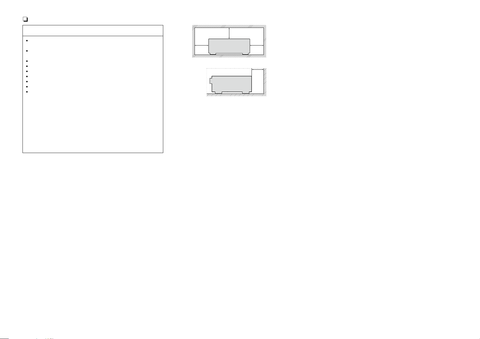
z For proper heat dispersal, do not install this unit in a confined
space, such as a bookcase or similar enclosure.
•More than 12 in. (0.3 m) is recommended.
•Do not place any other equipment on this unit.
II
Getting started
Basic version
Advanced version
Information
Thank you for purchasing this marantz product. To ensure proper operation, please read this owner’s manual carefully before using the product.
After reading them, be sure to keep them for future reference.
Contents
Getting started ·············································································· 1
Accessories ··················································································2
Features ························································································ 2
Cautions on handling ····································································3
Basic version ············································································4
Connections ··················································································· 5
Important information ··································································· 5
Connecting an HDMI-compatible device ······································ 7
Connecting a TV··········································································10
Connecting a Blu-ray Disc player ················································ 11
Connecting a DVD player ···························································· 12
Connecting a set-top box (Satellite tuner/cable TV) ···················· 12
Connecting a video cassette recorder ········································ 13
Connecting a digital camcorder ··················································13
Connecting an iPod or USB memory device to the USB port ·····14
Connecting an antenna ······························································· 15
Connecting a CD player ······························································ 15
Connecting a wireless receiver (RX101) ····································· 16
Connect a device that has a multichannel output terminal ········· 16
Connecting a external power amplifier ······································· 17
Connecting to a home network (LAN) ········································ 18
Settings ························································································ 19
Set up speakers (Audyssey® Auto Setup) ·································19
Making the network settings (Network Setup) ···························25
Playback (Basic operation) ························································· 26
Important information ································································· 26
Playing a Blu-ray Disc player/DVD player ···································· 28
Playing a CD player ····································································· 28
Playing an iPod············································································29
Playing a USB memory device ····················································31
Tuning in radio stations ······························································· 33
Playing a network audio ······························································ 35
Selecting a listening mode (Surround mode) ··························53
Selecting a listening mode··························································53
Advanced version ·······························································57
Speaker installation/connection (Advanced) ··························· 58
Install ··························································································58
Connect ······················································································60
Set up speakers ·········································································· 66
Connections (Advanced connection)·········································68
Connecting the remote control connectors ································ 68
Connecting the RS-232C connector ···········································68
Playback (Advanced operation) ················································· 69
Convenient functions ·································································· 69
Playback in ZONE2 (Separate room) ········································ 80
Audio output ··············································································· 80
Playback ······················································································ 81
Sleep timer function ···································································81
How to make detailed settings ·················································· 82
Menu map ··················································································82
Examples of menu screen displays ············································ 83
Examples of menu ······································································ 84
Inputting characters ··································································· 85
Audio Adjust ···············································································87
Information ·················································································92
System Setup ············································································· 93
Input Setup ··············································································· 107
Other settings ············································································ 113
Remote control settings ··························································· 113
Operating the connected devices by remote control unit ····114
Operating AV devices ······························································· 114
Registering preset codes ·························································· 115
Operating devices ····································································· 117
Operating learn function ··························································· 119
Information ···········································································121
Part names and functions·························································122
Front panel ················································································ 122
Display ······················································································ 123
Rear panel ················································································· 124
Remote control unit ·································································· 125
Other information ·····································································127
Trademark information ······························································127
Surround ··················································································· 128
Relationship between video signals and monitor output ·········· 132
Explanation of terms ································································· 133
Troubleshooting ········································································ 136
Resetting the microprocessor ··················································140
Specifications ············································································141
1
Accessories
Basic version
Advanced version
Information
vSee overleaf
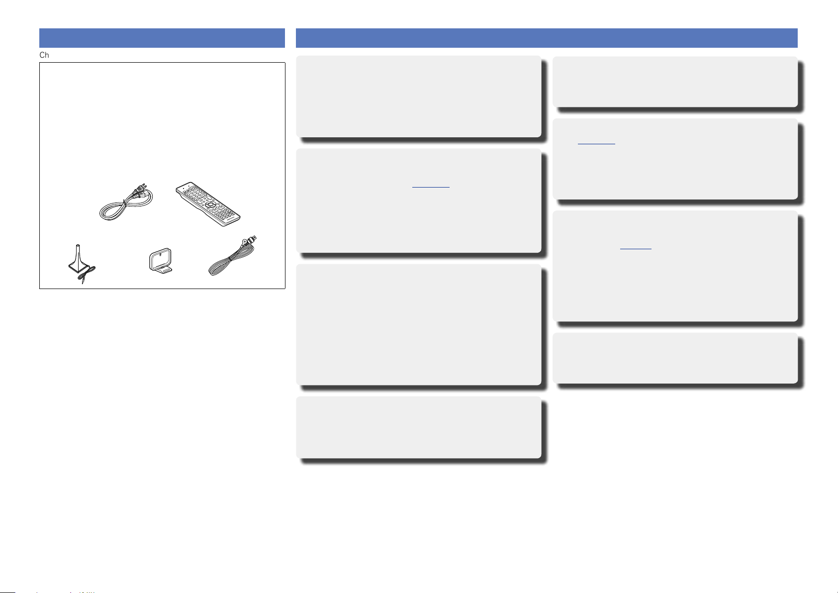
Check that the following parts are supplied with the product.
q Getting Started ........................................................................ 1
w CD-ROM (Owner’s manual) .................................................... 1
e Warranty card (for USA) .......................................................... 1
r Warranty card (for CANADA) ................................................... 1
t Power cord .............................................................................. 1
y Remote control unit (RC014SR) .............................................. 1
u R03/AAA batteries ................................................................... 2
i Setup microphone (ACM1H) ................................................... 1
o AM loop antenna ..................................................................... 1
Q0 FM indoor antenna .................................................................. 1
t y
o Q0i
Features
Fully discrete, identical quality and power for all
7 channels (100 W x 7ch, 8 Ω)
The unit is equipped with a power amplifier that reproduces
highfidelity sound in surround mode with equal quality and power
for all channels, true to the original sound.
The power amplifier circuit adopts a discrete-circuit configuration
that achieves high-quality surround sound reproduction.
Supports internet radio, music, and photograph
streaming
Supports AirPlay® (vpage72)
When connected to a network, this unit can play audio files and still
images such as photographs that are stored on your computer. You
can also listen to internet radio and a host of other online music
sources that use network technology. This unit also supports
AirPlay that lets you stream your music library from an iPhone,
iPad, iPod touch or iTunes.
Compatible with “Wizz App” for performing basic
operations of the unit with an iPhone or iPod
z1
touch
“Wizz App” is application software that allows you to perform
basic operations with an iPhone or iPod touch such as turning the
unit ON/OFF, controlling the volume, and switching the source.
z1 Download “Wizz App” from iTunes® App Store. The unit
needs to be connected to a LAN and the iPhone/iPod touch
needs to be connected to the same network by Wi-Fi (wireless
LAN).
Easy to use, Graphical User Interface
This unit is equipped with an easy to see “Graphical User Interface”
that uses menu displays and levels. The use of level displays
increases operability of the this unit.
Direct play for iPod® and iPhone® via USB
(vpage14)
Music data from an iPod can be played back if you connect the USB
cable supplied with the iPod via the USB port of this unit, and also
an iPod can be controlled with the remote control unit for this unit.
When an iPod is connected, merely pressing 21 starts playback
of music from the iPod.
Supports HDMI 1.4a with 3D, ARC, Deep Color,
“x.v.Color” , Auto Lip Sync and HDMI control
function (vpage7)
This unit can output 3D video signals input from a Blu-ray Disc
player to a TV that supports a 3D system. This unit also supports
the ARC (Audio Return Channel) function, which reproduces TV
sound with this unit via an HDMI cable used for connecting the
unit and a TVz2.
z2 The TV should support the ARC function.
6-HDMI inputs and 1-output
The unit is equipped with 6 HDMI input connectors for connecting
devices with HDMI connectors, such as a Blu-ray Disc player,
game machine, HD video camera, etc.
Setup Wizard, providing easy-to-follow setup
instructions
First select the language when prompted. Then simply follow the
instructions displayed on the TV screen to set up the speakers,
network, etc.
2

Features
Basic version
Advanced version
Information
High definition audio support
The unit is equipped with a decoder which supports high-quality
digital audio format for Blu-ray Disc players such as Dolby TrueHD,
DTS-HD Master Audio, etc.
M-XPort (marantz-eXtension Port) (vpage16)
This unit is equipped with the M-XPort, a marantz original innovation
that provides outstanding expandability. You can connect the
Wireless Receiver RX101 (sold separately) to this port.
Cautions on handling
•Before turning the power on
Check once again that all connections are correct and that there are
no problems with the connection cables.
•Power is supplied to some of the circuitry even when the unit is
set to the standby mode. When going on vacation or leaving home
for long periods of time, be sure to unplug the power cord from the
power outlet.
•About condensation
If there is a major difference in temperature between the inside of
the unit and the surroundings, condensation (dew) may form on
the operating parts inside the unit, causing the unit not to operate
properly.
If this happens, let the unit sit for an hour or two with the power
turned off and wait until there is little difference in temperature
before using the unit.
•Cautions on using mobile phones
Using a mobile phone near this unit may result in noise. If that
occurs, move the mobile phone away from this unit when it is in use.
•Moving the unit
Turn off the power and unplug the power cord from the power
outlet. Next, disconnect the connection cables to other system units
before moving the unit.
•About care
•Wipe the cabinet and control panel clean with a soft cloth.
•Follow the instructions when using a chemical cleaner.
•Benzene, paint thinner or other organic solvents as well as
insecticide may cause material changes and discoloration if brought
into contact with the unit, and should therefore not be used.
3
Basic
Basic version
Advanced version
Information
Basic version
version
Basic version
Here, we explain the connections and basic operation methods for this unit.
F Connections vpage5
F Settings vpage19
F Playback (Basic operation) vpage26
F Selecting a listening mode (Surround mode) vpage53
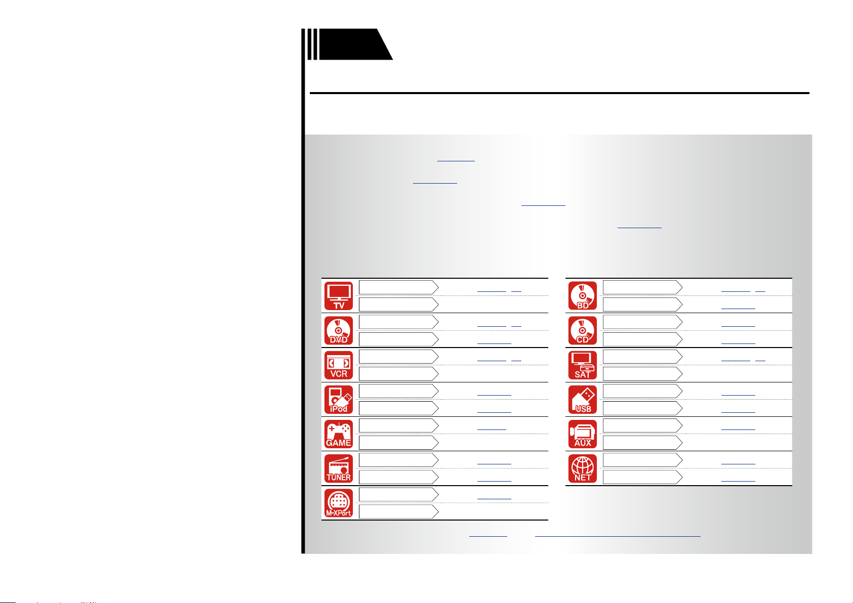
Connection
Playback
Connection
Playback
Connection
Playback
Connection
Playback
Connection
Playback
Connection
Playback
Connection
Playback
vpage8, 10
–
vpage8, 11
vpage28
vpage8, 13
–
vpage14
vpage29
vpage8
–
vpage15
vpage33
vpage16
–
Connection
Playback
Connection
Playback
Connection
Playback
Connection
Playback
Connection
Playback
Connection
Playback
For speaker connections, see page60, C page 6 “Connecting the speakers”.
4
vpage8, 11
vpage28
vpage15
vpage28
vpage8, 12
–
vpage14
vpage31
vpage13
–
vpage18
vpage35
Connections
Basic version
Advanced version
Information
Basic version
vSee overleaf
Important information
•Make connections as follows before using this unit. Select an
appropriate connection type according to the devices to be
connected.
•You may need to make some settings on this unit depending
on the connection method. Refer to each description for more
information.
•Select the cables (sold separately) according to the devices
being connected.
NOTE
•Do not plug in the power cord until all connections have been
completed (When the Setup wizard is running, follow the instructions
in the Setup wizard screen for making connections. ).
•When running the Setup wizard, turn off the power supply of
connected devices.
•When making connections, also refer to the operating instructions of
the other devices being connected.
•Be sure to connect the left and right channels properly (left with left,
right with right).
•Do not bundle power cords together with connection cables. Doing
so can result in noise.
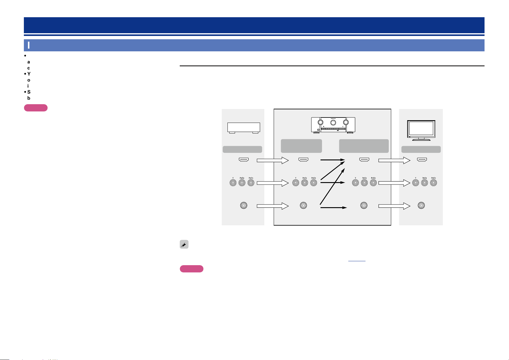
Converting input video signals for output (Video conversion function)
This unit is equipped with three types of video input connectors (HDMI, Component video and video) and three types of video output connectors
(HDMI, Component video and video).
Use the connectors corresponding to the devices to be connected.
This function automatically converts various formats of video signals input to this unit into the formats used to output the video signals from
this unit to a monitor.
GFlow of video signals for MAIN ZONEH
Video device
Output
HDMI connector
Input
(IN)
HDMI connector
This unit
Output
(MONITOR OUT)
HDMI
connector
Monitor (TV)
Input
HDMI connector
Component video
connectors
Video connector
•The video conversion function supports the NTSC, PAL, SECAM, NTSC 4.43, PAL-N, PAL-M and PAL-60 formats.
•Resolutions of HDMI-compatible TVs can be checked at “Monitor Info.” (vpage92).
Component video
connectors
Video connector
Component video
connectors
Video connector
Component video
connectors
Video connector
NOTE
•HDMI signals cannot be converted into analog signals.
•Component video input signals cannot be converted into Video format.
•When a non-standard video signal from a game machine or some other source is input, the video conversion function might not operate.
5

Important information
Basic version
Advanced version
Information
Basic version
Examples of screen display
•Menu screen •Status display screen
When the input source is
switched.
Menu
Audio Adjust
Information
Setup Wizard
System Setup
Input Setup
Surr.Parameter
Tone
AudysseySettings
Manual EQ
M-DAX
Audio Delay
SOURCE :BD
MODE
[Auto]
:STEREO
Status display: The operating status appears briefly on the screen
when the input source is switched or the volume is
changed.
NOTE
•If you operate the menu while playing back 3D video content or computer’s resolution (e.g. VGA), the
playback video is replaced by the menu screen. The playback video is not displayed behind the menu
screen.
•This unit does not show the status display while playing back 3D video content or computer’s resolution
(e.g. VGA).
•The menu screen and status display are displayed when this unit and a TV are connected by HDMI.
Furthermore, the menu screen and status display are not displayed when this unit and a TV are connected
by VIDEO and COMPONENT VIDEO.
When the volume is adjusted.
Master Volume -55.5dB
6
Connecting an HDMI-compatible device
Basic version
Advanced version
Information
Basic version
vSee overleaf
You can connect up to seven HDMI-compatible devices (6-inputs/1-output) to the unit.
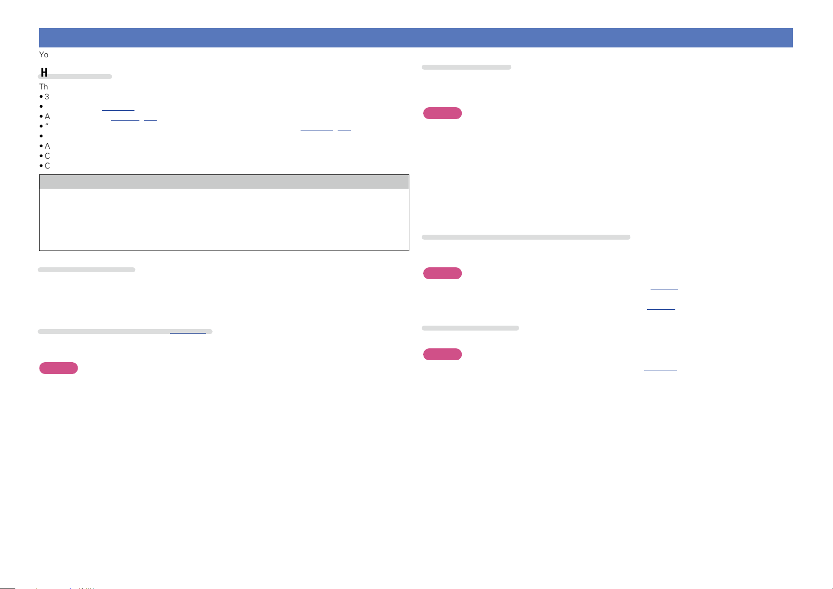
HDMI function
This unit supports the following HDMI functions:
•3D
•Deep Color (vpage133)
•Auto Lip Sync (vpage97, 133)
•“x.v.Color”, sYCC601 color, Adobe RGB color, Adobe YCC601 color (vpage133, 134)
•High definition digital audio format
•ARC (Audio Return Channel)
•Content Type
•CEC (HDMI control)
Copyright protection system
In order to play back digital video and audio such as BD-Video or DVD-Video via HDMI connection, both
this unit and TV or the player need to support the copyright protection system known as HDCP (Highbandwidth Digital Content Protection System). HDCP is copyright protection technology comprised of
data encryption and authentication of the connected AV devices. This unit supports HDCP.
•If a device that does not support HDCP is connected, video and audio are not output correctly. Read
the owner’s manual of your television or player for more information.
About HDMI cables
•When a device supporting Deep Color is connected, use a cable compatible with “High Speed HDMI
cable” or “High Speed HDMI cable with Ethernet”.
•When the ARC function is used, connect a device with a ”Standard HDMI cable with Ethernet” or “High
Speed HDMI cable with Ethernet” for HDMI 1.4a.
HDMI control function (vpage69)
This function allows you to operate external devices from the unit and operate the unit from external
devices.
NOTE
•The HDMI control function may not work depending on the device it is connected to and its settings.
•You cannot operate a TV or Blu-ray Disc player/DVD player that is not compatible with the HDMI control
function.
About 3D function
This unit supports input and output of 3D (3 dimensional) video signals of HDMI 1.4a.
To play back 3D video, you need a TV and player that provide support for the HDMI1.4a 3D function and
a pair of 3D glasses.
NOTE
•When playing back 3D video, refer to the instructions provided in the manual of your playback device
together with this manual.
•When playing back 3D video content, the menu screen or status display screen can be superimposed
over the image. However, the menu screen or status display screen cannot be superimposed over
certain 3D video content.
•If 3D video with no 3D information is input, the menu screen and status display on this unit are displayed
over the playback video.
•If 2D video is converted to 3D video on the television, the menu screen and status display on this unit
are not displayed correctly. To view the menu screen and status display on this unit correctly, turn the
television setting that converts 2D video to 3D video off.
About ARC (Audio Return Channel) function
The Audio Return Channel in HDMI 1.4a enables a TV, via a single HDMI cable, to send audio data “upstream”
to this unit.
NOTE
•To enable the ARC function, set “HDMI Control” to “ON” (vpage97).
•When connecting a TV that does not support the ARC function, a separate connection using an audio
cable is required. In this case, refer to “Connecting a TV” (vpage10) for the connection method.
About Content Type
HDMI 1.4a enables simple, automated picture setting selection with no user intervention.
NOTE
To enable the Content Type, set “Video Mode” to “Auto” (vpage110).
7
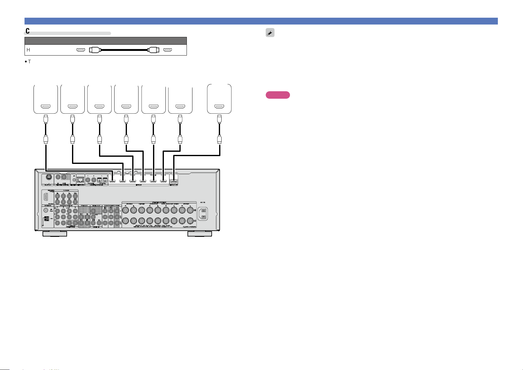
Cables used for connections
Basic version
Advanced version
Information
Basic version
vSee overleaf
Audio and video cable (sold separately)
HDMI cable
•This interface allows transfer of digital video signals and digital audio signals over a single HDMI cable.
Blu-ray
Disc
player
HDMI
OUT
DVD
player
HDMI
OUT
Set-top
box
HDMI
OUT
Video
cassette
recorder
HDMI
OUT
Game
console
HDMI
OUT
Digital
camcorder
HDMI
OUT
TV
HDMI
IN
Connecting an HDMI-compatible device
•When this unit is connected to other devices with HDMI cables, connect this unit and TV also with an
HDMI cable.
•When connecting a device that supports Deep Color, please use a “High Speed HDMI cable” or “High
Speed HDMI cable with Ethernet”.
•Video signals are not output if the input video signals do not match the monitor’s resolution. In this case,
switch the Blu-ray Disc/DVD player’s resolution to a resolution with which the monitor is compatible.
•When this unit and monitor are connected with an HDMI cable, if the monitor is not compatible with
HDMI audio signal playback, only the video signals are output to the monitor.
NOTE
The audio signal from the HDMI output connector (sampling frequency, number of channels, etc.) may be
limited by the HDMI audio specifications of the connected device regarding permissible inputs.
8

Connecting an HDMI-compatible device
Basic version
Advanced version
Information
Basic version
Connecting to a device equipped with a DVI-D connector
When an HDMI/DVI conversion cable (sold separately) is used, the HDMI video signals are converted to
DVI signals, allowing connection to a device equipped with a DVI-D connector.
NOTE
•No sound is output when connected to a device equipped with a DVI-D connector. Make separate audio
connections.
•Signals cannot be output to DVI-D devices that do not support HDCP.
•Depending on the combination of devices, the video signals may not be output.
nSettings related to HDMI connections
Set as necessary. For details, see the respective reference pages.
Input Assign (vpage109)
Set this to change the HDMI input connector to which the input source is assigned.
HDMI Setup (vpage97)
Make settings for HDMI video/audio output.
•Auto Lip Sync •HDMI Audio Out •HDMI Control
•Standby Source •P.Off Control
NOTE
The audio signal input from the HDMI input connector can be output as an output signal from the HDMI
output connector by setting the HDMI audio output destination to TV.
Audio signals input via the Analog/Coaxial/Optical input connectors cannot be output from the HDMI
output connector.
9
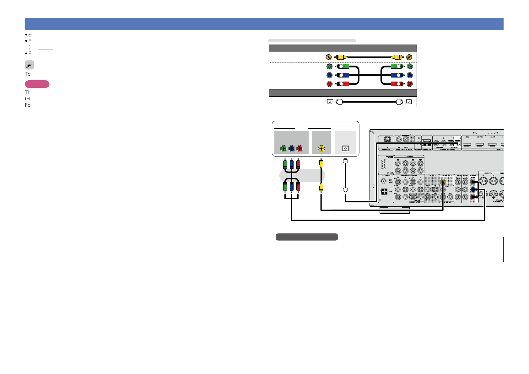
Connecting a TV
Basic version
Advanced version
Information
Basic version
•Select the connector to use and connect the device.
•For video connections, see “Converting input video signals for output (Video conversion function)”
(vpage5).
•For instructions on HDMI connections, see “Connecting an HDMI-compatible device” (vpage7).
To listen to TV audio through this device, use the optical digital connection.
NOTE
The optical connection is not required when a TV compatible with the ARC function (Audio Return Channel
(HDMI 1.4a standard function)) is connected to this unit via an HDMI connection.
For details, see “About ARC (Audio Return Channel) function” (vpage 7) or refer to the instruction
manual for your TV.
Cables used for connections
Video cable (sold separately)
Video cable
Component
video cable
Optical cable
TV
COMPONENT VIDEO
OUT
B PR
Y P
Audio cable (sold separately)
VIDEO
VIDEO
IN
Y
PB
PR
AUDIO
OPTICAL
OUT
Y
PB
PR
in Set as Necessary
Set this to change the digital input connector or component video input connector to which the input
source is assigned.
“Input Assign” (vpage109)
10
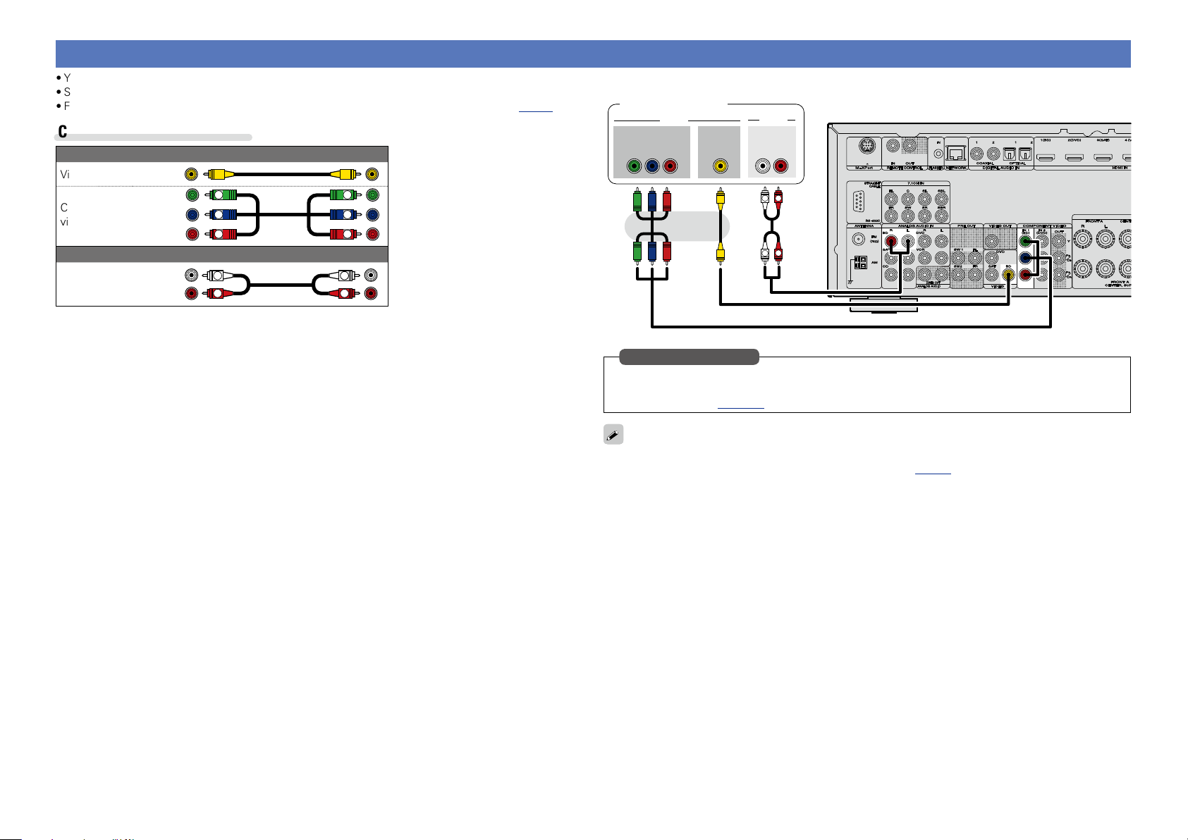
Connecting a Blu-ray Disc player
Basic version
Advanced version
Information
Basic version
•You can enjoy video and audio from a Blu-ray Disc.
•Select the connector to use and connect the device.
•For instructions on HDMI connections, see “Connecting an HDMI-compatible device” (vpage7).
Cables used for connections
Video cable (sold separately)
Video cable
Component
video cable
Audio cable
Y
PB
PR
Audio cable (sold separately)
L
R
Y
PB
PR
L
R
Blu-ray Disc player
AUDIO
AUDIO
OUT
L
L
RL
R
R
Y P
OUT
VIDEO
B PR
COMPONENT VIDEO
VIDEO
OUT
in Set as Necessary
Set this to change the digital input connector or component video input connector to which the input
source is assigned.
“Input Assign” (vpage109)
When you want to play back HD Audio (Dolby TrueHD, DTS-HD, Dolby Digital Plus, DTS Express) and Multichannel PCM with this unit, use an HDMI connection (vpage 7 “Connecting an HDMI-compatible
device”).
11
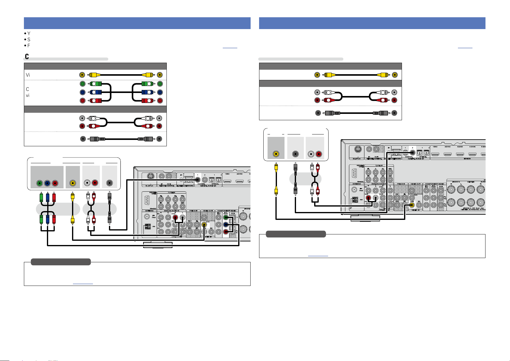
Connecting a DVD player
Basic version
Advanced version
Information
Basic version
•You can enjoy video and audio from a DVD.
•Select the connector to use and connect the device.
•For instructions on HDMI connections, see “Connecting an HDMI-compatible device” (vpage7).
Connecting a set-top box (Satellite tuner/cable TV)
•You can watch satellite or cable TV.
•Select the connector to use and connect the device.
•For instructions on HDMI connections, see “Connecting an HDMI-compatible device” (vpage7).
Cables used for connections
Video cable (sold separately)
Video cable
AUDIO
OUT
L
L
Y
PB
PR
L
R
RL
R
R
Component
video cable
Audio cable
Coaxial
digital cable
DVD player
COMPONENT VIDEO
OUT
B PR
Y P
Audio cable (sold separately)
VIDEO AUDIO
VIDEO
OUT
COAXIAL
OUT
Cables used for connections
Video cable (sold separately)
Video cable
Y
PB
PR
Audio cable
Coaxial
L
R
digital cable
Satellite tuner/Cable TV
VIDEO
VIDEO
OUT
Audio cable (sold separately)
L
R
AUDIO
COAXIAL
OUT
AUDIO
OUT
L
L
RL
R
R
L
R
in Set as Necessary
Set this to change the digital input connector or component video input connector to which the input
source is assigned.
“Input Assign” (vpage109)
in Set as Necessary
Set this to change the digital input connector or component video input connector to which the input
source is assigned.
“Input Assign” (vpage109)
12
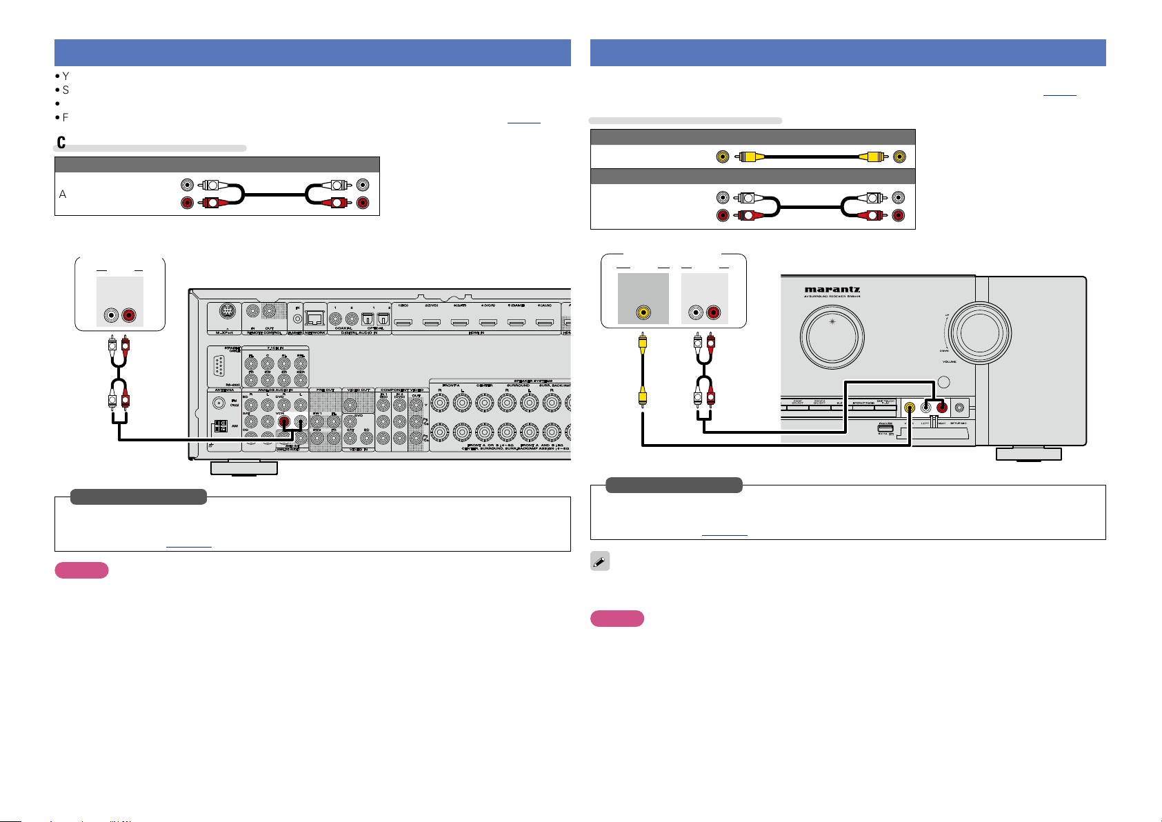
Connecting a video cassette recorder
Basic version
Advanced version
Information
Basic version
•You can record video onto a video cassette tape.
•Select the connector to use and connect the device.
•When recording analog audio, use the analog connection.
•For instructions on HDMI connections, see “Connecting an HDMI-compatible device” (vpage7).
Cables used for connections
Audio cable (sold separately)
Audio cable
L
R
L
R
Connecting a digital camcorder
•You can enjoy video and audio from a digital camcorder.
•For instructions on HDMI connections, see “Connecting an HDMI-compatible device” (vpage7).
Cables used for connections
Video cable (sold separately)
Video cable
Audio cable (sold separately)
Audio cable
L
R
L
R
Video cassette
recorder
AUDIO
AUDIO
OUT
RL
R
L
R
L
in Set as Necessary
Set this to change the digital input connector or component video input connector to which the input
source is assigned.
“Input Assign” (vpage109)
NOTE
To record video signals through this unit, use the same type of video cable for connection between this
unit and the player as used for connection between this unit and the recorder.
Digital camcorder
AUDIOVIDEO
VIDEO
OUT
AUDIO
OUT
L
L
RL
R
R
in Set as Necessary
Set this to change the digital input connector or component video input connector to which the input
source is assigned.
“Input Assign” (vpage109)
You can enjoy games by connecting a game machine via the AUX INPUT connector. In this case, select
the input source to “AUX”.
NOTE
When a non-standard video signal from a game machine or some other source is input, the video conversion
function might not operate. In this case, use the monitor output of the same connector as the input.
13
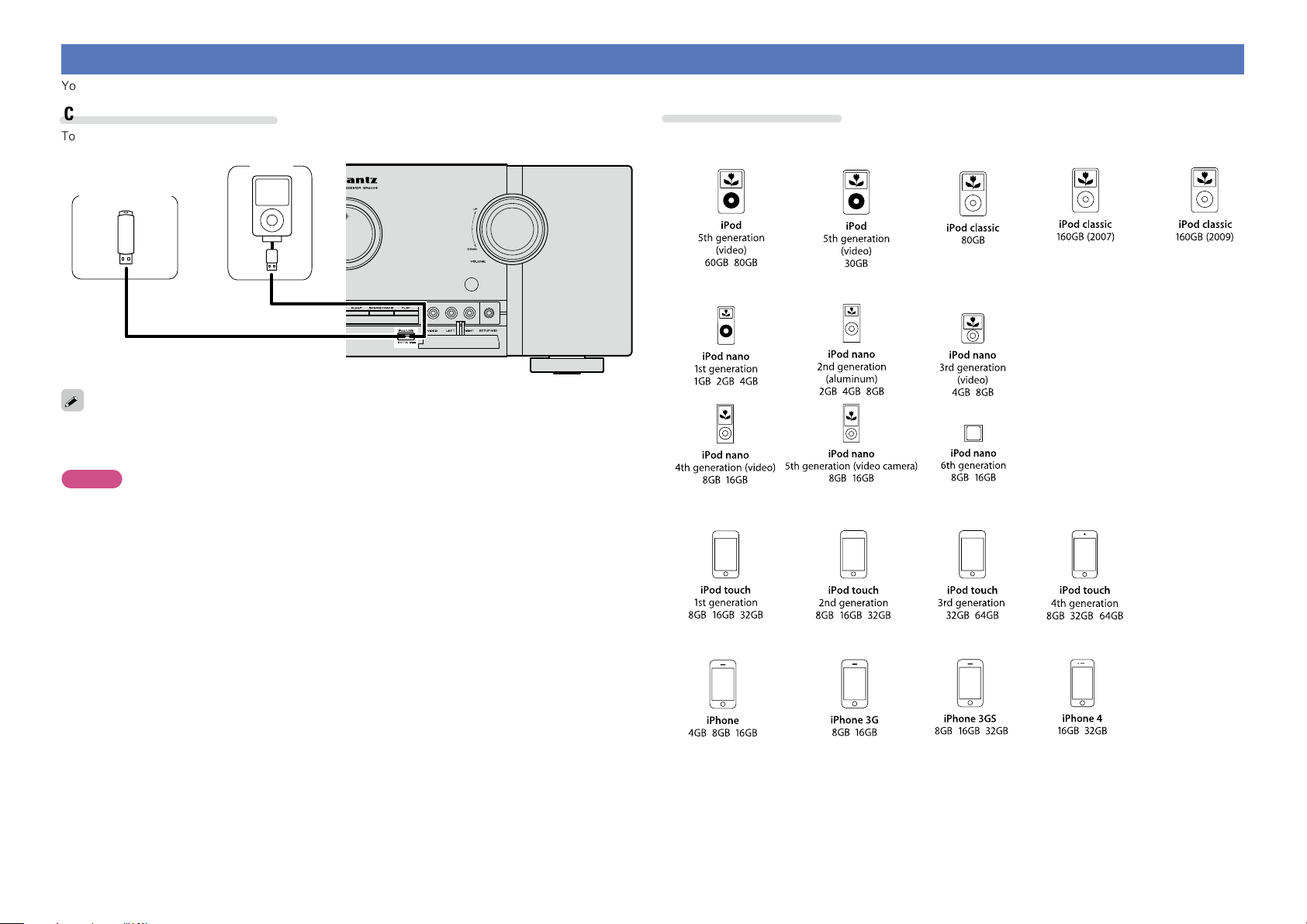
Connecting an iPod or USB memory device to the USB port
Basic version
Advanced version
Information
Basic version
You can enjoy music stored on an iPod or USB memory device.
Cables used for connections
To connect an iPod to this unit, use the USB cable supplied with the iPod.
iPod
USB memory
device
or
marantz does not guarantee that all USB memory devices will operate or receive power. When using a
portable USB connection type HDD of the kind to which an AC adapter can be connected to supply power,
use the AC adapter.
NOTE
•USB memory devices will not work via a USB hub.
•Do not use an extension cable when connecting a USB memory device. This may cause radio interference
with other devices.
•This unit does not support playback on an iPad. Do not connect an iPad to the unit.
•When connecting an iPhone to this unit, keep the iPhone at least 20 cm away from this unit. If the iPhone
is kept closer to this unit and a telephone call is received by the iPhone, noise may be output from this
device.
Supported iPod models
•iPod / iPod classic
•iPod nano
•iPod touch
•iPhone
14
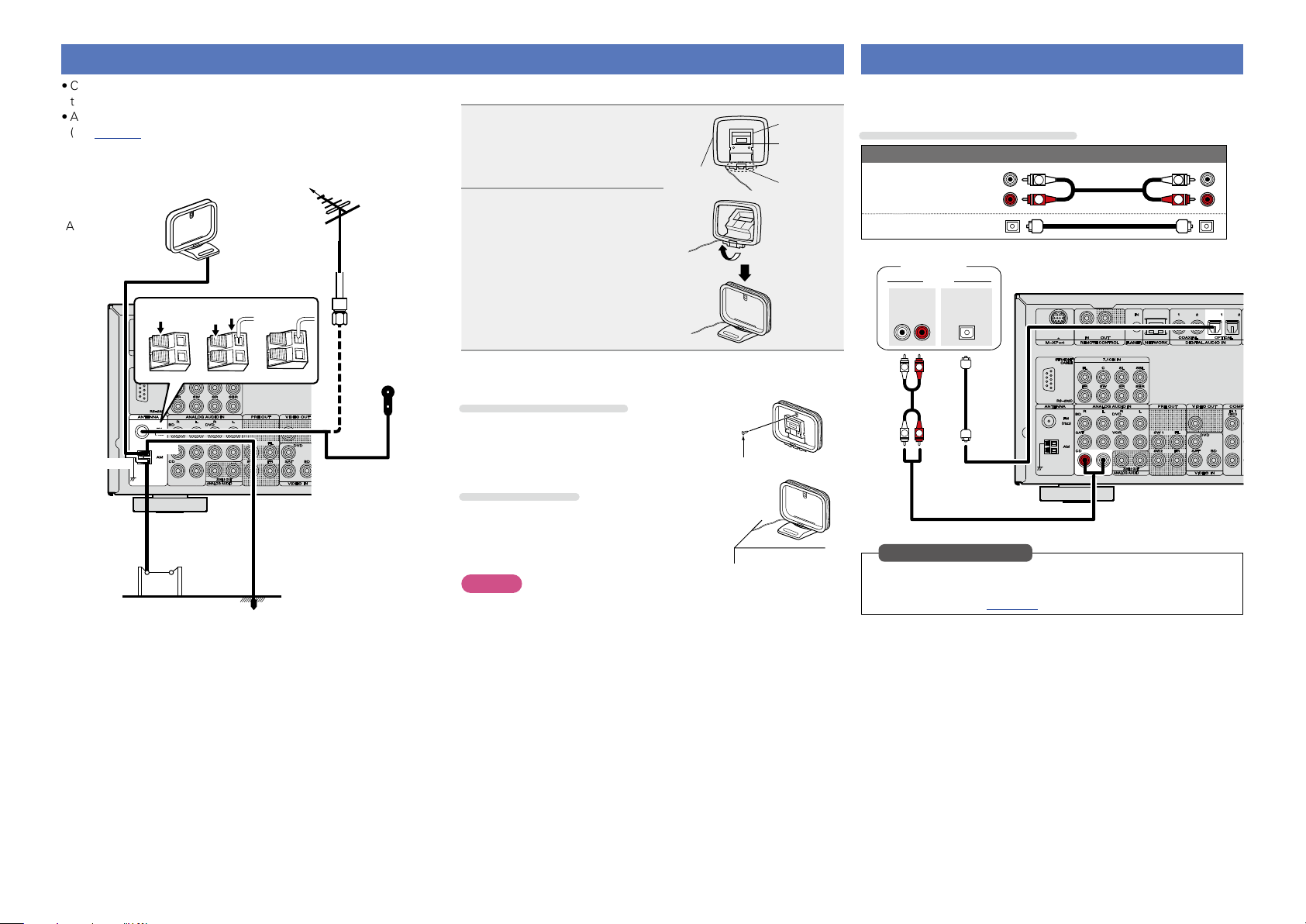
Connecting an antenna
Basic version
Advanced version
Information
Basic version
•Connect the FM antenna or AM loop antenna supplied with the unit
to enjoy listening to radio broadcasts.
•After connecting the antenna and receiving a broadcast signal
(vpage 33 “Listening to FM/AM broadcasts”), fix the antenna
with tape in a position where the noise level becomes minimal.
Direction of broadcasting station
FM outdoor
AM loop antenna
(supplied)
w eq
Black
White
antenna
75 Ω coaxial
cable
FM indoor
antenna
(supplied)
nAM loop antenna assembly
Put the stand section
1
through the bottom of the
loop antenna from the
rear and bend it forward.
Loop
antenna
Insert the projecting part
2
into the square hole in
the stand.
nUsing the AM loop antenna
Suspending on a wall
Suspend directly on a wall without assembling.
Standing alone
Use the procedure shown above to assemble.
Stand
Square
hole
Projecting
part
Nail, tack, etc.
Connecting a CD player
•You can enjoy CD sound.
•Select the connector to use and connect the device.
Cables used for connections
Audio cable (sold separately)
Audio cable
Optical cable
CD player
AUDIO
OUT
RL
R
L
R
L
AUDIO
OPTICAL
OUT
L
R
L
R
AM outdoor
antenna
Ground
NOTE
•Do not connect two FM antennas simultaneously.
•Even if an external AM antenna is used, do not disconnect the AM
loop antenna.
•Make sure the AM loop antenna lead terminals do not touch metal
parts of the panel.
•If the signal has noise interference, connect the ground terminal
(GND) to reduce noise.
•If you are unable to receive a good broadcast signal, we recommend
installing an outdoor antenna. For details, inquire at the retail store
where you purchased the unit.
15
in Set as Necessary
Set this to change the digital input connector to which the input
source is assigned.
“Input Assign” (vpage109)
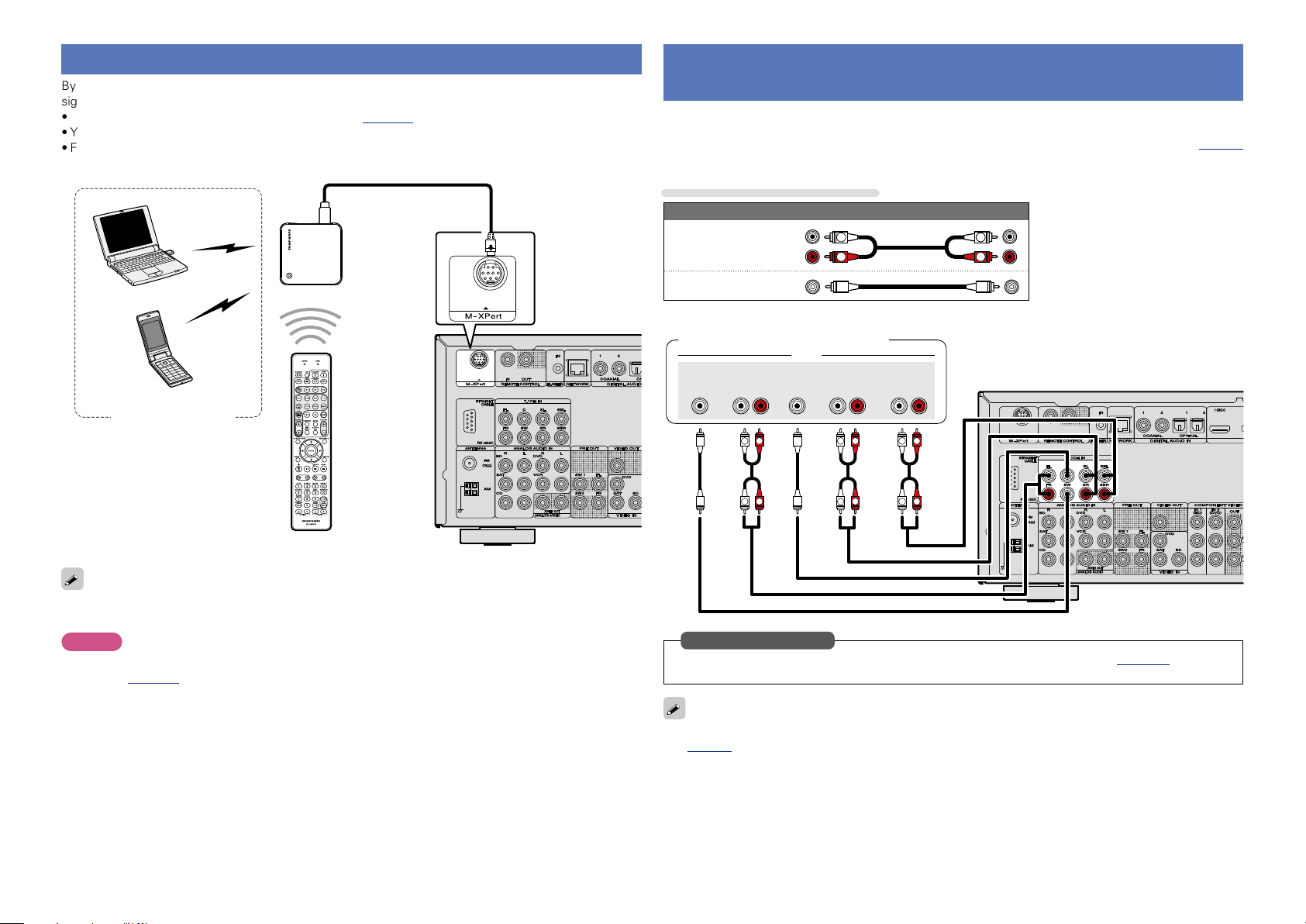
Connecting a wireless receiver (RX101)
Basic version
Advanced version
Information
Basic version
By connecting a wireless receiver RX101 (sold separately) to this unit, you can receive and playback audio
signals from other devices using the Bluetooth Communication Function.
•Use a Bluetooth device that is A2DP compatible (vpage133 “A2DP”).
•You can also use wireless receiver RX101 as an external IR receiver.
•For instructions on the wireless receiver settings, refer to the RX101’s operating instructions.
Wireless receiver RX101
Bluetooth device
(A2DP Compatibility)
Connect a device that has a multichannel output terminal
•You can connect this unit to an external device fitted with multi-channel sound audio output jacks to enjoy
music and video.
•The video signal can be connected in the same way as a Blu-ray Disc player / DVD player (vpage11
“Connecting a Blu-ray Disc player”).
Cables used for connections
Audio cable (sold separately)
Audio cable
L
R
Audio cable
Blu-ray Disc player / DVD player /
External decoder
SUB-
WOOFER
FRONT
L
AUDIO
CENTER SURROUND
SURROUND
RL
R
L
BACK
RL
R
RL
R
L
L
R
Remote control unit
You can enjoy listening to music by connecting a wireless receiver via the M-XPort input connector. In this
case, set the input source to “M-XPort”.
NOTE
To use wireless receiver RX101 as external IR receiver, set the remote sensor function of this unit to
disable (vpage113 “Remote control settings”).
R
L
R
L
R
L
in Set as Necessary
To play analog signals input from 7.1CH IN connectors, set “Input Mode” (vpage111) to “7.1CH
IN”.
When a device is connected to the SBL/SBR terminal of 7.1CH IN connectors, set “Amp Assign”
(vpage94) to “NORMAL”.
16
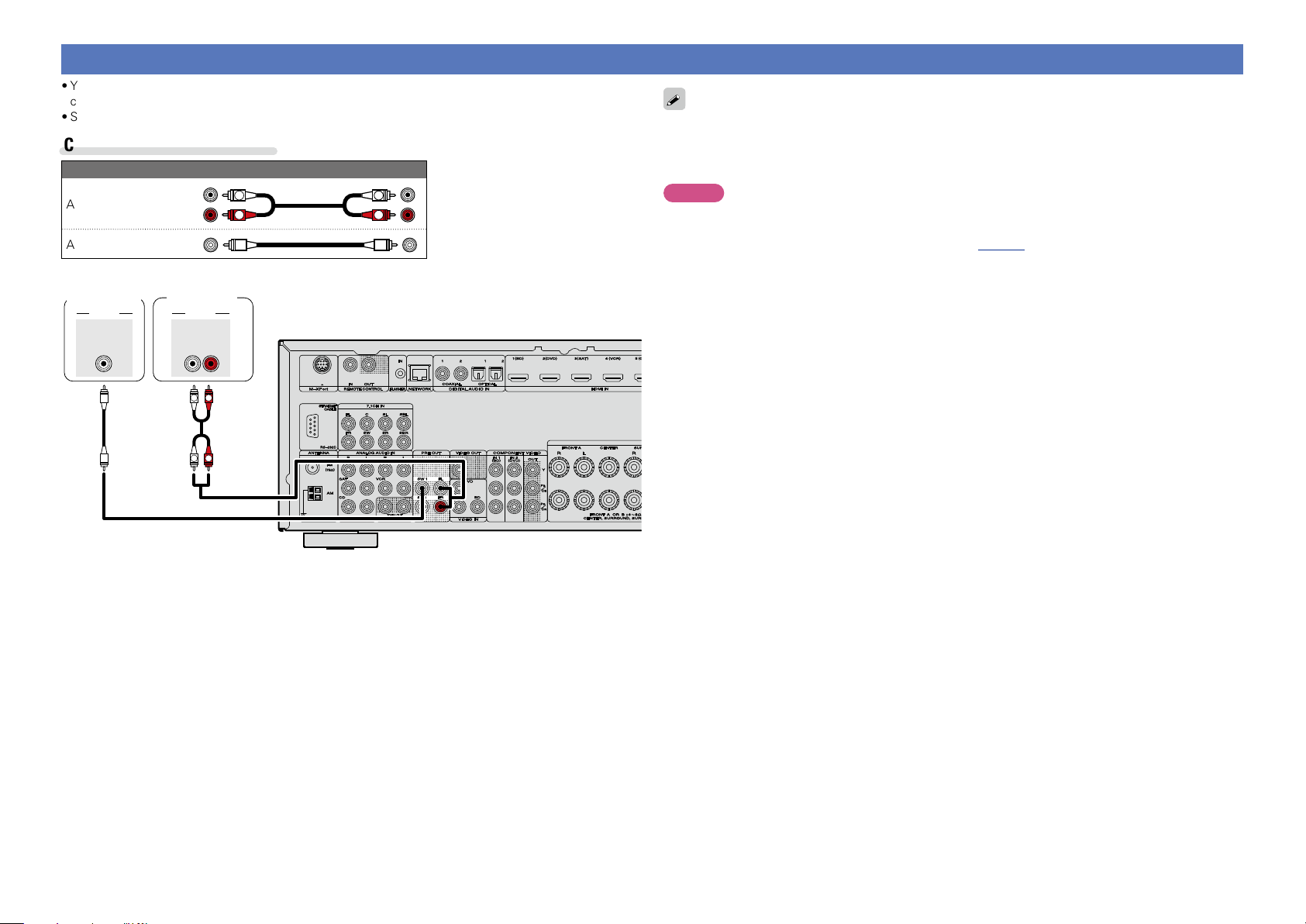
Connecting a external power amplifier
Basic version
Advanced version
Information
Basic version
•You can use this unit as a pre-amp by connecting a commercially available power amp to the PRE OUT
connector. Adding a power amp to each of the channels provides an even greater sound presence.
•Select the terminal to use and connect the device.
Cables used for connections
Audio cable (sold separately)
Audio cable
Audio cable
Subwoofer
SUB-
WOOFER
1
Power
amplifier
AUDIOAUDIO
FRONT
RL
R
L
R
L
L
R
L
R
•When using just one surround back speaker, connect it to the left channel (L) terminal.
•Use the volume control on the subwoofer to control subwoofer volume.
•If the subwoofer volume sounds low, use the volume control provided on the subwoofer to adjust the
volume.
NOTE
•When external power amplifier have been connected to PRE OUT terminals, do not connect the speakers
to the speaker terminals.
•Depending on the settings in the “Amp Assign” (vpage94) menu or listening mode, the channel
output from the SBL terminal or SBR terminal of the PRE OUT terminal differs.
17
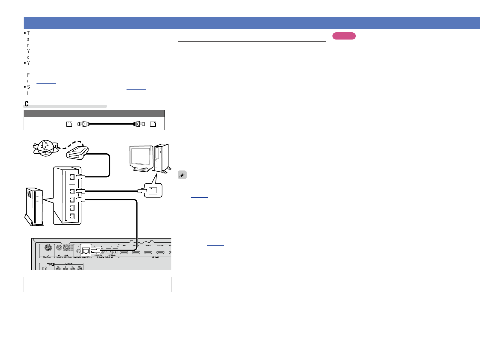
Connecting to a home network (LAN)
Basic version
Advanced version
Information
Basic version
•This unit lets you play via your home network (LAN) music files
stored on a computer and music content such as that from Internet
radio.
You can also operate this unit from a computer using the Web
control function.
•You can update by downloading the latest firmware from the
marantz website.
For more information, on the menu, select “Firmware Update”
(vpage104).
•See “Network Setup” on the menu (vpage 99) for more
information on network setting.
Cables used for connections
Cable (sold separately)
Ethernet
cable
Computer
Modem
Internet
Required system
nBroadband internet connection
nModem
Device that connects to the broadband circuit and conducts
communications on the Internet.
A type that is integrated with a router is also available.
nRouter
When using this unit, we recommend you use a router equipped
with the following functions:
•Built-in DHCP server
This function automatically assigns IP addresses on the LAN.
•Built-in 100BASE-TX switch
When connecting multiple devices, we recommend a switching
hub with a speed of 100 Mbps or greater.
n Ethernet cable (CAT-5 or greater recommended)
•Use only a shielded STP or ScTP LAN cable which is available at
retailer.
•Some flat type Ethernet cables are easily affected by noise.
We recommend using a normal type cable.
NOTE
•A contract with an ISP is required to connect to the Internet.
No additional contract is needed if you already have a broadband
connection to the Internet.
•The types of routers that can be used depend on the ISP. Contact an
ISP or a computer shop for details.
•marantz assumes no responsibility whatsoever for any
communication errors or troubles resulting from customer’s
network environment or connected devices.
•This unit is not compatible with PPPoE. A PPPoE-compatible router
is required if you have a contract for a type of line set by PPPoE.
•Do not connect an NETWORK connector directly to the LAN port/
Ethernet connector on your computer.
•To listen to audio streaming, use a router that supports audio
streaming.
To WAN side
To LAN port
To LAN port
Router
For connections to the Internet, contact an ISP (Internet
Service Provider) or a computer shop.
LAN port/
Ethernet
connector
•If you have an Internet provider contract for a line on which network
settings are made manually, make the settings at “Network Setup”
(vpage99).
•With this unit, it is possible to use the DHCP and Auto IP functions
to make the network settings automatically.
•When using this unit with the broadband router’s DHCP function
enabled, this unit automatically performs the IP address setting and
other settings.
When using this unit connected to a network with no DHCP
function, make the settings for the IP address, etc., at “Network
Setup” (vpage99).
•When setting manually, check the setting contents with the network
administrator.
18
Settings
Basic version
Advanced version
Information
Basic version
vSee overleaf
Here, we explain “Audyssey® Auto Setup”, which allows you to
automatically make the optimal settings for your speakers, and
“Network Setup”, which allows you to connect this unit to a home
network (LAN).
This unit lets you play via your home network (LAN) music files stored
on a computer and music content such as that from Internet radio.
n Set up speakers (Audyssey® Auto Setup)
(vpage19)
n Making the network settings (Network Setup)
(vpage25)
Playback (Basic operation) (vpage26)
Selecting a listening mode (Surround mode)
(vpage53)
Playback (Advanced operation) (vpage69)
Set up speakers (Audyssey® Auto Setup)
The acoustic characteristics of the connected speakers and
listening room are measured and the optimum settings are made
automatically. This is called “Audyssey® Auto Setup”.
To perform measurement, place the setup microphone in
multiple locations all around the listening area. For best results,
we recommend you measure in six or more positions, as shown
in the illustration (up to eight positions).
•When performing Audyssey® Auto Setup, Audyssey MultEQ® XT/
Audyssey Dynamic EQ®/Audyssey Dynamic Volume® functions
become active (vpage89).
•To set up the speakers manually, use “Speaker Setup”
(vpage94) on the menu.
NOTE
•Make the room as quiet as possible. Background noise can disrupt
the room measurements. Close windows, silence cell phones,
televisions, radios, air conditioners, fluorescent lights, home
appliances, light dimmers, or other devices as measurements may
be affected by these sounds.
•Cell phones should be placed away from all audio electronics during
the measurement process as Radio Frequency Interference (RFI)
may cause measurement disruptions (even if the cell phone is not
in use).
•Do not unplug the setup microphone from the main unit until
Audyssey® Auto Setup is completed.
•Do not stand between the speakers and setup microphone or allow
obstacles in the path while the measurements are being made. This
will cause inaccurate readings.
•Loud test sounds may be played during Audyssey® Auto Setup. This
is part of normal operation. If there is background noise in room,
these test signals will increase in volume.
•Operating
the measurements will cancel the
measurements.
•Measurement cannot be performed when
headphones are connected.
VOLUME +, –
during
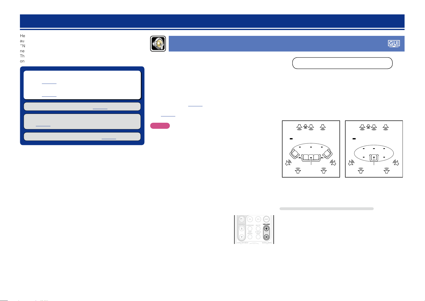
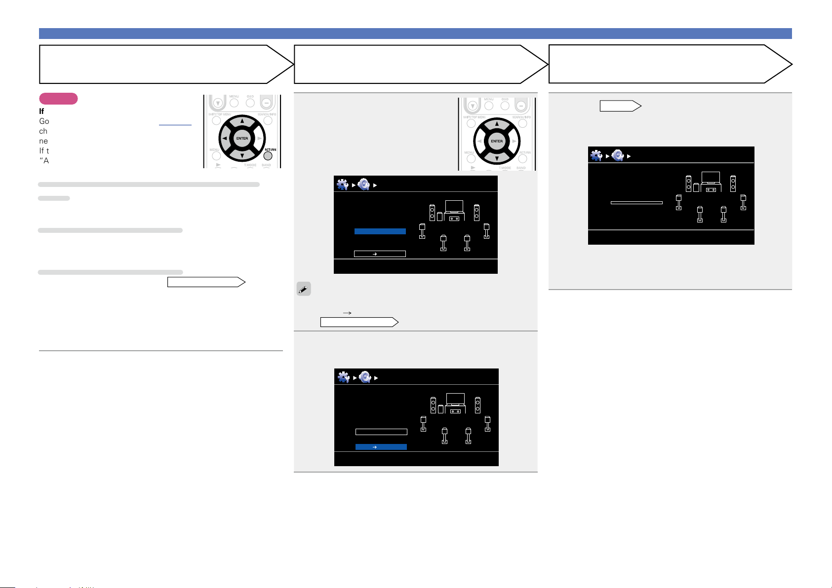
About setup microphone placement
•Measurements are performed by placing the setup microphone
successively at multiple positions throughout the entire listening
area, as shown in GExample qH. For best results, we recommend
you measure in six or more positions, as shown in the illustration
(up to eight positions).
•Even if the listening environment is small as shown in GExample wH,
measuring at multiple points throughout the listening environment
results in more effective correction.
GExample qH GExample wH
FL SW C FR
( : Measuring positions)
SL
FL Front speaker (L) SL Surround speaker (L)
FR Front speaker (R) SR Surround speaker (R)
C Center speaker SBL Surround back speaker (L)
SW Subwoofer SBR Surround back speaker (R)
M
*
SBL SBR
SR
FL SW C FR
( : Measuring positions)
SL
M
*
SBL SBR
SR
About the main listening position (*M)
The main listening position is the position where listeners would
normally sit or where one would normally sit alone within the listening
environment. Before starting Audyssey® Auto Setup, place the setup
microphone in the main listening position. Audyssey MultEQ® XT uses
the measurements from this position to calculate speaker distance,
level, polarity, and the optimum crossover value for the subwoofer.
19
Set up speakers (Audyssey® Auto Setup)
Basic version
Advanced version
Information
Basic version
vSee overleaf
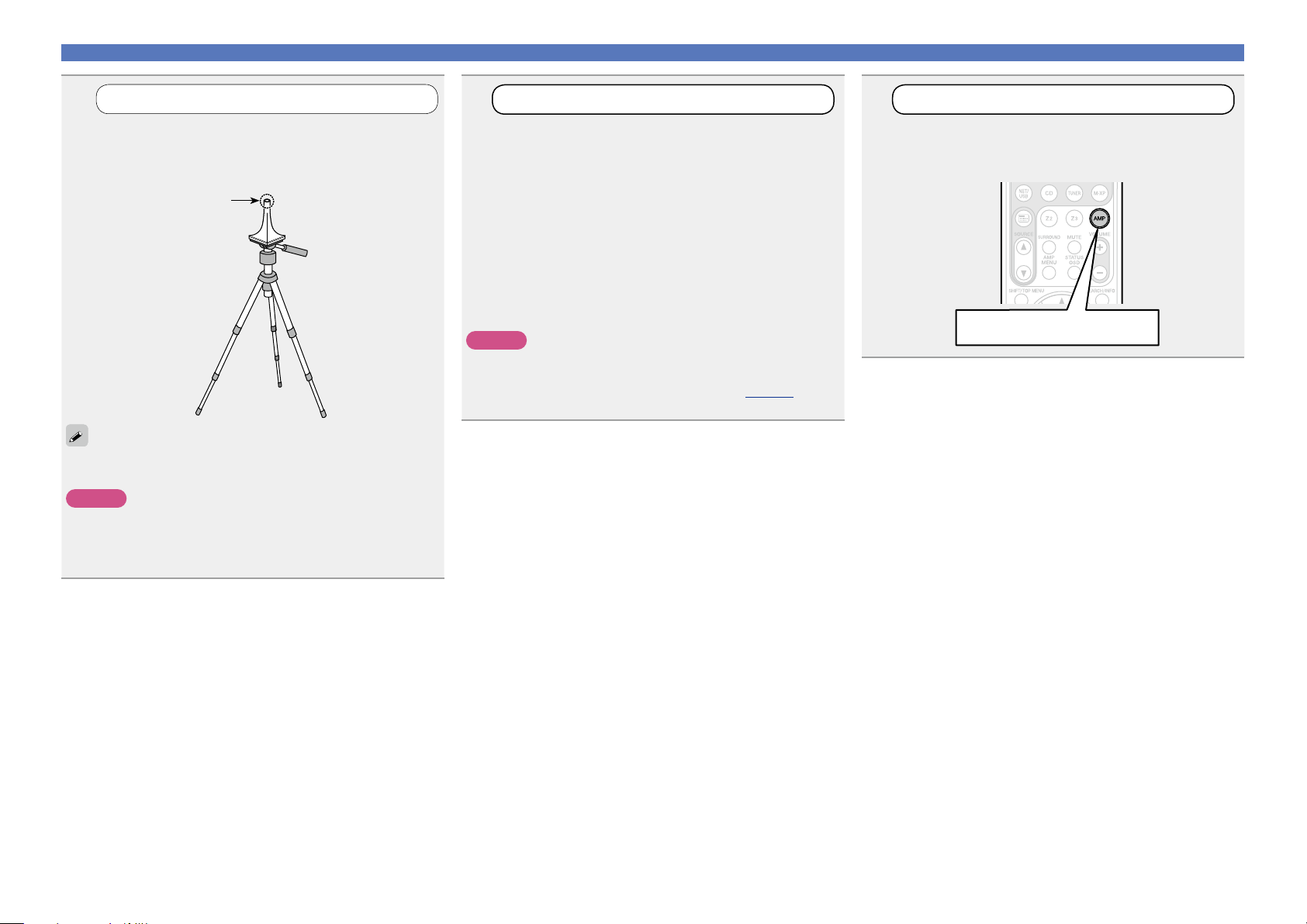
1
Mount the setup microphone on a tripod or stand
and place it in the main listening position.
When placing the setup microphone, adjust the height of the
sound receptor to the level of the listener’s ear.
If you do not have a tripod or stand, set up the microphone on, for
example, a seat without a back.
NOTE
•Do not hold the setup microphone in your hand during
measurements.
•Avoid placing the setup microphone close to a seat back or wall as
sound reflections may give inaccurate results.
Set up the microphone
Sound receptor
Setup
microphone
2
If using a subwoofer capable of the following
adjustments, set up the subwoofer as shown below.
n When using a subwoofer with a direct mode
Set the direct mode to “On” and disable the volume adjustment
and crossover frequency setting.
n When using a subwoofer without a direct mode
Make the following settings:
•Volume : “12 o’clock position”
•Crossover frequency : “Maximum/Highest Frequency”
•Low pass filter : “Off”
•Standby mode : “Off”
NOTE
When you use two subwoofers, please adjust the subwoofer
volume controls individually so that each subwoofer level is as close
as possible to 75 dB using the test tone (vpage 96) before
Audyssey® Auto Setup.
Set up the subwoofer
3
n Set up the operation mode
Set up the remote control unit
Press AMP to set the remote control unit to AMPoperation mode.
Press AMP
20
Set up speakers (Audyssey® Auto Setup)
Basic version
Advanced version
Information
Basic version
vSee overleaf
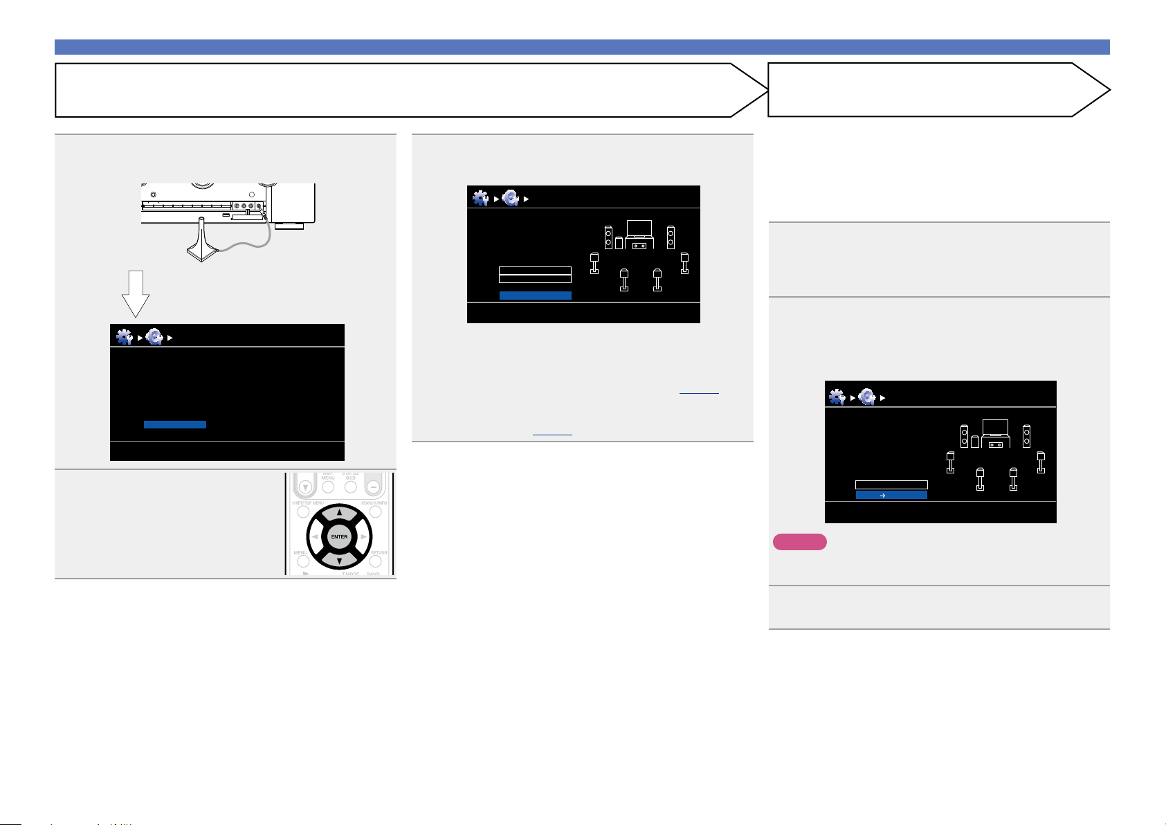
STEP 1
Preparation
Connect the setup microphone to the SETUP MIC
4
jack of this unit.
When the setup microphone is
connected, the following screen is
displayed.
Audyssey Auto Setup
Preparation
Connect the speakers and place then according
to the recommendations in the manual.
Next
Select “Next” and then press
5
ENTER.
MultEQ XT
[RETURN][ENTER] Enter Cancel
Use ui to select “Auto Setup Start” and then press
6
ENTER.
Audyssey Auto Setup MultEQ XT
Preparation
Set the following items
if necessary.
Amp Assign
Channel Select
Auto Setup Start
[RETURN][ENTER] Enter Cancel
Here, we explain setup using the example of 7.1-channel speaker
playback using surround back speakers.
For setup of surround speaker systems other than 7.1-channels,
follows steps 4 and 5 in “Set up “Amp Assign”” (vpage66).
If unused channels are set with “Channel Select”, measuring time
can be shortened. For setting, perform steps 7 to 10 of “Set up
“Channel Select”” (vpage67).
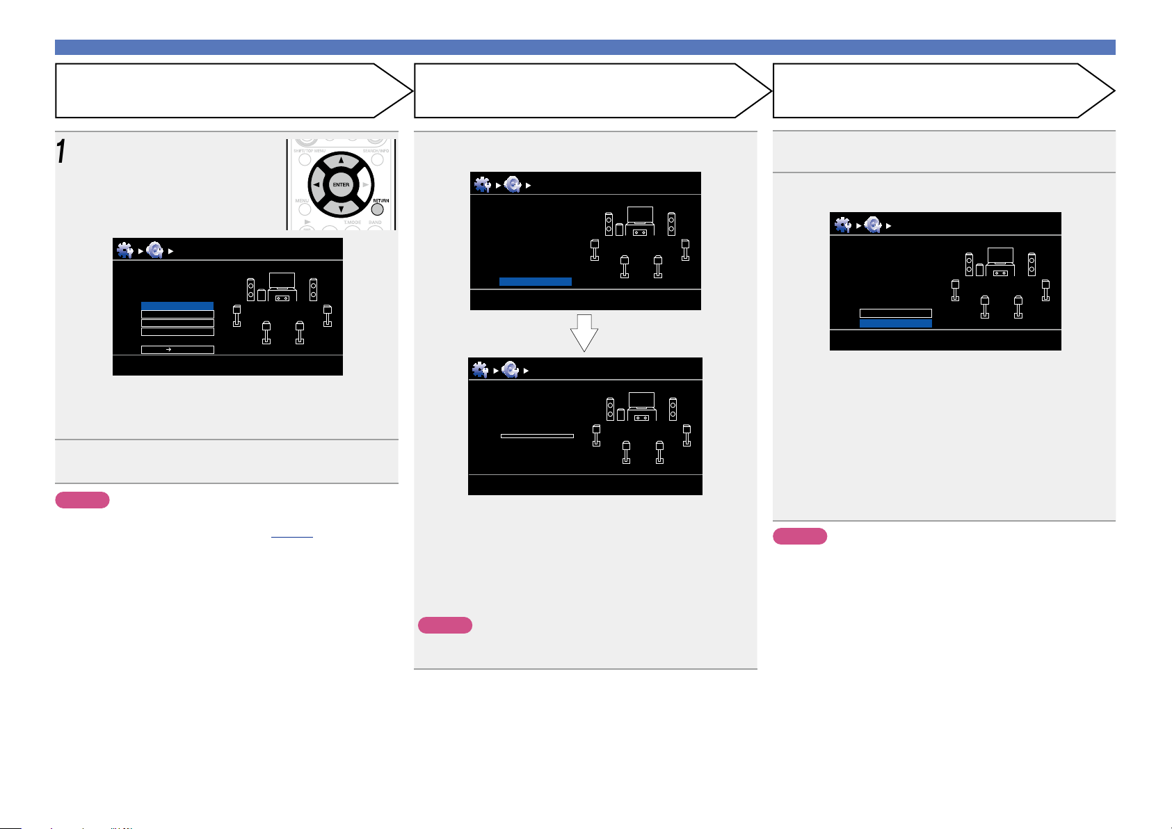
STEP 2
Detect & Measure (Main)
•In STEP 2, you will perform measurements at the main listening
position.
•This step automatically checks the speaker configuration and speaker
size, and calculates the channel level, distance, and crossover
frequency.
It also corrects distortion in the listening area.
Select “Measure” and then press ENTER.
7
When measuring begins, a test tone is output from each
speaker.
•Measurement requires several minutes.
The detected speakers are displayed.
8
•The illustration below shows an example of when the front
speakers, center speaker, subwoofer, and surround speakers have
been detected.
Audyssey Auto Setup MultEQ XT
Detect Check
Front
Center
Subwoofer
Surround
S.Back
Retry
Next Measure
Yes
Yes
Yes
Yes
Yes
2 spkrs
[ENTER] Enter
[RETURN] Cancel
21
NOTE
If a connected speaker is not displayed, the speaker may not be
connected correctly. Check the speaker connection.
Use ui to select “Next → Measure” and then press
9
ENTER.
Set up speakers (Audyssey® Auto Setup)
Basic version
Advanced version
Information
Basic version
vSee overleaf
STEP 2 (Continued)
Detect & Measure (Main)
NOTE
If “Caution!” is displayed:
Go to “Error messages” (vpage 24),
check any related items, and perform the
necessary procedures.
If the problem is resolved, return and restart
“Audyssey® Auto Setup”.
When performing Audyssey® Auto Setup over
again
Press ui to select “Retry”, and then press ENTER.
When measuring has stopped
q Press RETURN, to the “Cancel Auto Setup?” prompt is displayed.
w Press o to select “Yes”, then press ENTER.
Setting up the speakers again
Repeat the operation from step 4 of
•In STEP 3, you will perform measurements at multiple positions (two
to eight positions) other than the main listening position.
•Just one position can be measured but measuring multiple positions
increases the accuracy of the correction of acoustic distortion within
the listening area.
STEP 1 Preparation
.
STEP 3
Measure (2nd – 8th)
Move the setup microphone to
10
position 2, use ui to select
“Measure”, and then press
ENTER.
The measurement of the second
position starts. Measurements can be
made in up to eight positions.
Audyssey Auto Setup MultEQ XT
Measure (2nd)
Please place the
microphone at ear
height at 2nd
listening position.
Measure
Next Calculate
[RETURN][ENTER] Enter Cancel
If you want to omit measurements from the next position onward,
select “Next Calculate”.
(Go to
11
STEP4 Calculate
)
Repeat step 10, measuring positions 3 to 8.
When measurement of position 8 is completed, a
“Measurements finished.” message is displayed.
STEP 4
Calculate
On the
12
Calculate”, and then press ENTER.
Measuring results are analyzed, and the frequency response of
each speaker in the listening room is determined.
•Analysis takes several minutes to complete. The time required for
this analysis depends on the number of speakers connected.
The more connected speakers there are, the longer it takes to
perform analysis.
STEP 3
Calculate
Now calculating
Please wait
0%
screen, use ui to select “Next →
Audyssey Auto Setup MultEQ XT
Audyssey Auto Setup MultEQ XT
Measure (Finish)
Measurements finished.
Retry
Next Calculate
22
[RETURN][ENTER] Enter Cancel
Set up speakers (Audyssey® Auto Setup)
Basic version
Advanced version
Information
Basic version
STEP 5
Check
Use ui to select the item you
13
want to check, and then press
ENTER.
Audyssey Auto Setup
Check
Check processing resuit.
To proceed, press
“Next”.
Sp.Config. Check
Distance Check
Ch.Level Check
Crossover Check
Next Store
•Subwoofers may measure a greater reported distance than
the actual distance due to added electrical delay common in
subwoofers.
•If you want to check another item, press RETURN.
Use ui to select “Next → Store” and then press
14
ENTER.
NOTE
•If the result differs from the actual connection status, or if “Caution!”
is displayed, see “Error messages” (vpage 24). Then carry out
Audyssey® Auto Setup again.
• If you change speaker positions or orientation, perform Audyssey®
Auto Setup again to find the optimal equalizer settings.
MultEQ XT
[RETURN][ENTER] Enter Cancel
STEP 6
Store
Select “Store” and then press ENTER.
15
Save the measurement results.
Audyssey Auto Setup MultEQ XT
Store
Press “Store” to
store calculation
result.
Store
[RETURN][ENTER] Enter Cancel
Audyssey Auto Setup MultEQ XT
Store
Now storing
Please wait
0%
•Saving the results requires about 10 seconds.
•If the measuring results are not to be saved, press RETURN. A
message “Cancel auto setup?” will be displayed. Press o then
select “Yes”. All the measured Audyssey® Auto Setup data will
be erased.
•During saving of measurements results, “Now storing Please
wait...” is displayed. When saving is completed, “Storing complete.
Auto Setup is now finished.” is displayed.
NOTE
During saving of measurement results, be sure not to turn off the
power.
Finish
Unplug the setup microphone from the unit’s SETUP
16
MIC jack.
Set Audyssey Dynamic Volume®.
17
Audyssey Auto Setup MultEQ XT
Finish
Storing complete.
Auto Setup is now finished.
Please unplug microphone.
Turn on Dynamic Volume?
Yes
No
[ENTER] Exit
•This feature adjusts the output volume to the optimal level while
constantly monitoring the level of the audio input to the unit.
Optimal volume control is performed automatically without any
loss in the dynamism and clarity of the sound when, for example,
the volume suddenly increases for commercials shown during
television programs.
n When turning Dynamic Volume® on
•Use u to select “Yes”, and then press ENTER.
The unit automatically enters “Medium” mode.
n When turning Dynamic Volume® off
•Use i to select “No”, and then press ENTER.
NOTE
After performing Audyssey® Auto Setup, do not change the speaker
connections or subwoofer volume. In event of a change, perform
Audyssey® Auto Setup again.
23

Set up speakers (Audyssey® Auto Setup)
Basic version
Advanced version
Information
Basic version
Error messages
NOTE
•An error message is displayed if Audyssey® Auto Setup could not be completed due to speaker placement, the measurement environment, etc. If this happens, check the relevant items, be sure to take the necessary
measures, then perform Audyssey® Auto Setup over again.
•If the result still differs from the actual connection status after remeasurement or the error message still appears, it is possible that the speakers are not connected properly. Turn this unit off, check the speaker
connections and repeat the measurement process from the beginning.
•Be sure to turn off the power before checking speaker connections.
Examples Error details Measures
Audyssey Auto Setup
Caution!
Microphone or Speaker is none
Retry
MultEQ XT
•The connected setup microphone is broken, or a device other than the
supplied setup microphone is connected.
•Not all speakers could be detected.
•The front L speaker was not properly detected.
•Connect the included setup microphone to the SETUP MIC jack of this unit.
•Check the speaker connections.
Audyssey Auto Setup
Caution!
Ambient noise is too high or level is too low
Retry
Audyssey Auto Setup
Caution! Speaker:None
Front R
Retry
Audyssey Auto Setup
Caution! Speaker:Phase
Front R
Skip
Retry
MultEQ XT
MultEQ XT
MultEQ XT
•There is too much noise in the room for accurate measurements to be
made.
•Speaker or subwoofer sound is too low for accurate measurements to be
made.
•The displayed speaker could not be detected.
(The screen on the left indicates that the front right speaker cannot be
detected.)
•The displayed speaker is connected with the polarity reversed.
(The screen on the left indicates that the polarity phases of the front right
speakers are reversed.)
•Either turn off any device generating noise or move it away.
•Perform again when the surroundings are quieter.
•Check the speaker installation and the direction in which the speakers are
facing.
•Adjust the subwoofer’s volume.
•Check the connections of the displayed speaker.
•Check the polarity of the displayed speaker.
•For some speakers, this error message may be
displayed even if the speaker is properly connected.
If you are sure the connection is correct, press ui
to select “Skip”, then press ENTER.
24
Set up speakers (Audyssey® Auto Setup)
Basic version
Advanced version
Information
Basic version
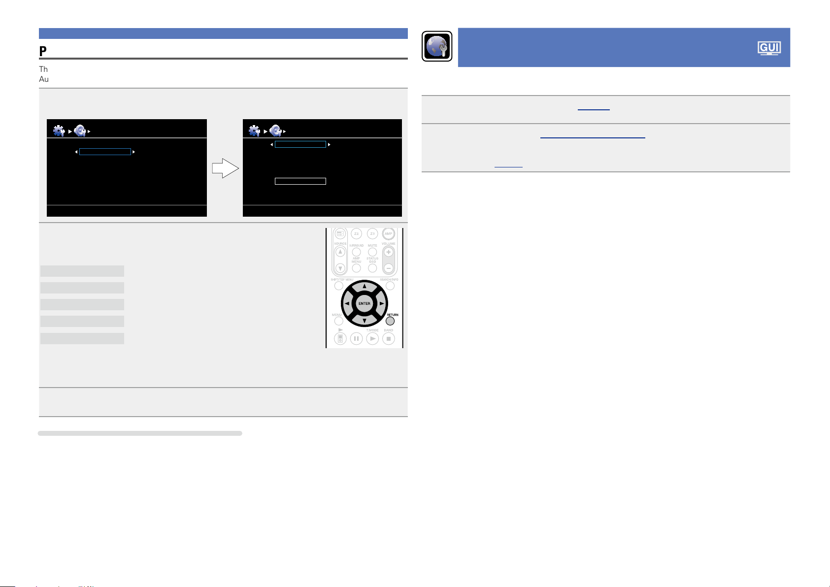
Parameter Check
This function enables you to check the measurement results and equalizer characteristics after Audyssey
Auto Setup.
Use ui to select “Parameter Check” and then press ENTER.
1
Auto Setup
Auto Setup
Parameter Check
Sp. Config. Check
Distance Check
Ch. Level Check
Crossover Check
EQ Check
Use ui to select the item you want to check, then press ENTER
2
or p.
Measurement results for each speaker are displayed.
Sp. Config. Check
Distance Check
Ch. Level Check
Crossover Check
Check the speaker configuration.
Check the distance.
Check the channel level.
Check the crossover frequency.
Parameter Check
Sp. Config. Check
Distance Check
Ch. Level Check
Crossover Check
EQ Check
Restore
Making the network settings (Network Setup)
®
This unit can be connected to a home network (LAN) to listen to Internet radio or play back music files and
still image (JPEG) files stored on a computer.
Connect the Ethernet cable (vpage 18 “Connecting to a home network (LAN)”).
1
Turn on this unit (C page 5 “Getting Started”).
2
This unit performs automatic network setup due to the DHCP function.
When connecting to a network that has no DHCP function, perform the setting in “Network
Connect.” (vpage99).
EQ Check
•If “EQ Check” is selected, press ui to select equalizing curve (“Audyssey” or “Audyssey Flat”) to
be checked.
Use o p to switch the display between the different speakers.
Check the equalizer.
Press RETURN.
3
The confirmation screen reappears. Repeat step 2.
Retrieving Audyssey® Auto Setup settings
If you set “Restore” to “Yes”, you can return to Audyssey® Auto Setup measurement result (value
calculated at the start by MultEQ® XT) even when you have changed each setting manually.
25
Playback (Basic operation)
Basic version
Advanced version
Information
Basic version
BD
vSee overleaf
Settings (vpage19)
n Selecting the input source (vpage26)
n Adjusting the master volume (vpage27)
n Turning off the sound temporarily (vpage27)
n Playing a Blu-ray Disc player/DVD player
(vpage28)
n Playing a CD player (vpage28)
n Playing an iPod (vpage29)
n Tuning in radio stations (vpage33)
n Playing a network audio (vpage35)
n Playing a USB memory device (vpage31)
Selecting a listening mode (Surround mode)
(vpage53)
Playback (Advanced operation) (vpage69)
Important information
Before starting playback, make the connections between the different
devices and the settings on the unit.
NOTE
Also refer to the operating instructions of the connected devices
when playing them.
Selecting the input source
Press the input source select button
(BD, DVD, SAT, TV, NET/USB, CD,
TUNER or M-XP) twice to be played
back.
When an input source select button (BD,
DVD, SAT, TV, CD, NET/USB, TUNER or
M-XP) is pressed once, the unit switches
to device selected by the operating mode of
the remote control. If the input source select
button is then pressed again twice, the input
source for the unit is switched.
•When 21 is pressed, the input source of this unit is switched
to “NET/USB” and the connected iPod is automatically played
(vpage30 “iPod play function”).
•Select input source “AUX” to play back music from an audio system
connected to the AUX IN connector.
•The input source “GAME” is selected to playback from a game
device connected to GAME connector of HDMI IN.
•Select the input source “VCR”, “GAME” or “AUX” using one of the
following methods.
•SOURCE df button on the remote control unit
(“Using the SOURCE df button on the remote control unit”
provided on the right)
•INPUT SELECTOR knob on the main unit
(“Using the knob on the main unit” provided on the right)
•“Source Select” menu
(“Using the “Source Select” menu”(vpage27)
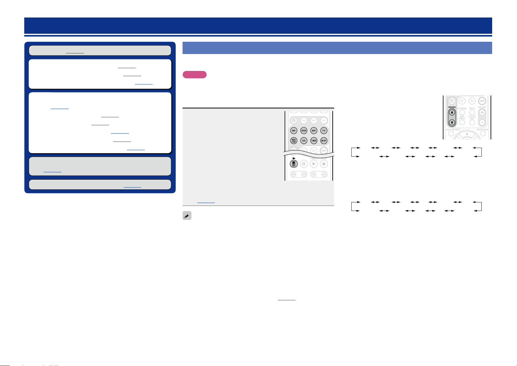
You can also use the following operation to select an input
source.
nUsing the SOURCE d f button on the remote
control unit
Press SOURCE d or SOURCE f.
•Every time you press
SOURCE f, the input source switches in
the following order.
BD DVD
SOURCE d or
SAT GAMEVCR AUX
CD NET/USBTUNERM-XPort
TV
nUsing the knob on the main unit
Turn INPUT SELECTOR.
•Every time you turn
in the following order.
BD DVD
INPUT SELECTOR, the input source switches
SAT GAMEVCR AUX
CD NET/USBTUNERM-XPort
TV
26
nUsing the “Source Select” menu
Basic version
Advanced version
Information
Basic version
BD
Source Select
Player
BD
DVD
CD
M-XPort
USB/iPod
Video
SAT
TV
VCR
GAME
AUX
q Press 3.
Display the “Source Select” menu.
w Use uio p to select the input source,
then press ENTER.
The input source is set and the source
selection menu is turned off.
•When using with an iPod connected directly to the USB port of this
unit, select “iPod/USB” for the input source.
•Input sources that are not going to be used can be set ahead of time.
Make this setting at “Source Delete” (vpage103).
•To turn off the source selection menu without selecting an input
source, press 3 again.
•When 3 is pressed, the AMP-operation mode starts automatically
(vpage114).
The currently selected input
source is highlighted.
Tuner
TUNER
[ENTER] Enter[ ] Move
Network
Favorites
Internet Radio
Media Server
Flickr
Pandora
Napster
Rhapsody
Adjusting the master volume
Use VOLUME +, – to adjust the
volume.
n When the “Volume Display” setting
(vpage103) is “Relative”
GAdjustable rangeH
– – –
–80.5dB – 18.0dB
n When the “Volume Display” setting (vpage103) is
“Absolute”
GAdjustable rangeH
•The variable range differs according to the input signal and channel
level setting.
You can also operate via the main unit. In this case, perform the
following operations.
Turn VOLUME to adjust the volume.
0.0 – 99.0
Turning off the sound temporarily
Press MUTE.
•“MUTE” appears on the display.
appears on a TV screen.
•
•The sound is reduced to the level set at “Mute Level” (vpage103).
•To cancel, press MUTE again. Muting can also be canceled by
adjusting the master volume.
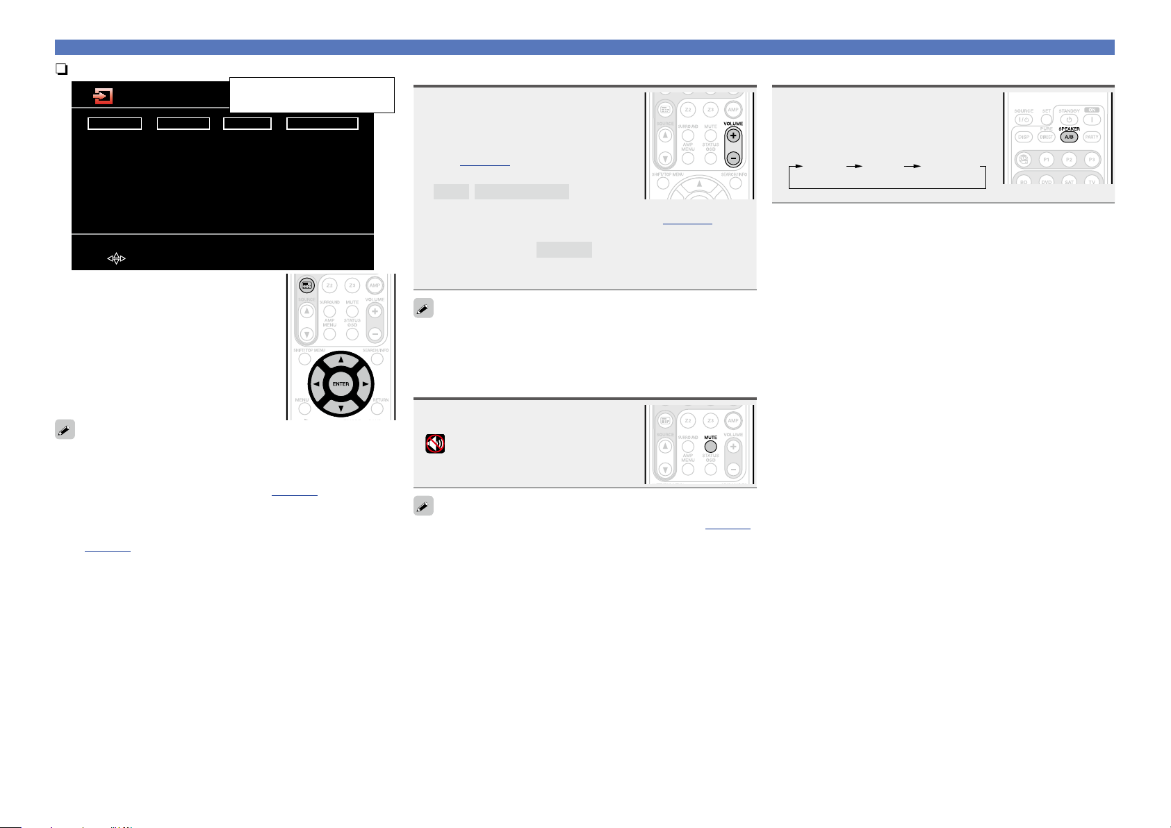
Important information
Set the front speakers to be used
Press SPEAKER A/B.
•Each time you press SPEAKER A/B,
the front speaker setting will change as
follows.
Front A Front A+BFront B
27
 Loading...