

Page 1
Service
BD7004
BD7004 /
U1B
Manual
SECTION PAGE
1. TECHNICAL SPECIFICATIONS............................................................................................1
2. SERVICE HINTS AND TOOLS .............................................................................................4
3. WARNING AND LASER SAFETY INSTRUCTION ...............................................................5
4. LASER BEAM SAFETY PRECAUTIONS .............................................................................6
5. IMPORTANT SAFETY PRECAUTIONS ...............................................................................7
6. STANDARD NOTES FOR SERVICING ................................................................................9
7. CABINET DISASSEMBLY INSTRUCTIONS .......................................................................13
8. HOW TO INITIALIZE THE BLU-RAY DISC PLAYER ........................................................ 17
9. FIRMWARE RENEWAL MODE ..........................................................................................18
10. FIRMWARE RENEWAL MODE (Network Update) ..............................................................20
11. SERVICE MODE ..................................................................................................................21
12. TRAY LOCK MODE .............................................................................................................23
13. TROUBLESHOOTING .........................................................................................................24
14. BLOCK DIAGRAMS ............................................................................................................32
15. SCHEMATIC DIAGRAMS / CBA AND TEST POINTS .......................................................38
16. WAVEFORMS ......................................................................................................................97
17. WIRING DIAGRAM .............................................................................................................98
18. LEAD IDENTIFICATIONS .................................................................................................. 99
19. EXPLODED VIEW AND PARTS LIST ...............................................................................101
BLU-RAY DISC Player
TABLE OF CONTENTS
S0053-1V02DM/DG1004
Please use this service manual with referring to the user guide (D.F.U.) without fail.
修理の際は、必ず取扱説明書を準備し操作方法を確認の上作業を行ってください。
BD7004
Copyright 2010 D&M Holdings Inc. All rights reserved.
WARNING: Violators will be prosecuted to the maximum extent possible.
Ver. 2
Please refer to the
MODIFICATION NOTICE.
Page 2
MARANTZ DESIGN AND SERVICE
USA
MARANTZ AMERICA, INC
100 CORPORATE DRIVE
MAHWAH, NEW JERSEY 07430
USA
EUROPE / TRADING
D&M EUROPE B. V.
P. O. BOX 8744, BUILDING SILVERPOINT
BEEMDSTRAAT 11, 5653 MA EINDHOVEN
THE NETHERLANDS
PHONE : +31 - 40 - 2507844
FAX : +31 - 40 - 2507860
KOREA
D&M SALES AND MARKETING KOREA LTD.
CHUNG JIN B/D., #1001,
53-5, WONHYORO 3 GA, YONGSAN-GU,
SEOUL, 140-719, KOREA
PHONE : +82 - 2 - 323 - 2155
FAX : +82 - 2 - 323 - 2154
CANADA
D&M Canada Inc.
5-505 APPLE CREEK BLVD.
MARKHAM, ONTARIO L3R 5B1
CANADA
PHONE : 905 - 415 - 9292
FAX : 905 - 475 - 4159
JAPAN
D&M BUILDING, 2-1 NISSHIN-CHO,
KAWASAKI-KU, KAWASAKI-SHI,
KANAGAWA, 210-8569 JAPAN
D&M Holdings Inc.
CHINA
D&M SALES AND MARKETING SHANGHAI LTD.
ROOM.808 SHANGHAI AIRPORT CITY TERMINAL
NO.1600 NANJING (WEST) ROAD, SHANGHAI,
CHINA. 200040
TEL : 021 - 6248 - 5151
FAX : 021 - 6248 - 4434
Using superior design and selected high grade components,
Only original
MARANTZ
parts can insure that your
MARANTZ
MARANTZ
company has created the ultimate in stereo sound.
product will continue to perform to the specications for
which it is famous.
Parts for your
MARANTZ
ORDERING PARTS :
equipment are generally available to our National Marantz Subsidiary or Agent.
Parts can be ordered either by mail or by Fax.. In both cases, the correct part number has to be specied.
The following information must be supplied to eliminate delays in processing your order :
1. Complete address
2. Complete part numbers and quantities required
3. Description of parts
4. Model number for which part is required
5. Way of shipment
6. Signature : any order form or Fax. must be signed, otherwise such part order will be considered as null and void.
NOTE ON SAFETY :
Symbol Fire or electrical shock hazard. Only original parts should be used to replaced any part marked with symbol .
Any other component substitution (other than original type), may increase risk of re or electrical shock hazard.
安全上の注意:
がついている部品は、安全上重要な部品です。必ず指定されている部品番号のものを使用して下さい。
SHOCK, FIRE HAZARD SERVICE TEST :
CAUTION : After servicing this appliance and prior to returning to customer, measure the resistance between either primary
AC cord connector pins (with unit NOT connected to AC mains and its Power switch ON), and the face or Front Panel of
product and controls and chassis bottom.
Any resistance measurement less than 1 Megohms should cause unit to be repaired or corrected before AC power is applied,
and veried before it is return to the user/customer.
Ref. UL Standard No. 60065.
In case of difculties, do not hesitate to contact the Technical
Department at above mentioned address.
080702MZ
Page 3

1.TECHNICALSPECIFICATIONS
SIGNALSYSTEM
NTSCcolor
APPLICABLEDISCS
(1) BD/DVD-VideoDiscs
1-layer12cmsingle-sideddiscs,2-layer12cm
single-sideddiscs,2-layer12cmdouble-sideddiscs
(1layerperside)
(2) BD-RE/BD-R(RecordedinBDMVformat)
1-layer12cmsingle-sideddiscs,2-layer12cm
single-sideddiscs
1-layer8cmsingle-sideddiscs,2-layer8cmsinglesideddiscs
(3) DVD-R
1-layer12cmsingle-sideddiscs,2-layer12cm
single-sideddiscs
1-layer8cmsingle-sideddiscs,2-layer8cmsinglesideddiscs
(4) DVD-RW
1-layer12cmsingle-sideddiscs
1-layer8cmsingle-sideddiscs
(5) Compactdiscs(audioCD)
12cmdiscs,8cmdiscs
(6) CD-RW/-R
12cmdiscs,8cmdiscs
APPLICABLEMEMORYCARDS
(1) SDMemoryCard
(2) SDHCMemoryCard
(3) miniSDCard
(4) microSDCard
VIDEOOUTPUT
Youtputlevel:1Vp-p(75Ω/ohms)
Outputconnectors:Pinjack,1set
COMPONENTOUTPUT
Youtputlevel:1Vp-p(75Ω/ohms)
PB/CBoutputlevel:0.648Vp-p(75Ω/ohms)
PR/CRoutputlevel:0.648Vp-p(75Ω/ohms)
Outputconnectors:Pinjacks,1set
HDMIOUTPUT
Outputjack:19-pinHDMIterminal,1set
HDMIver.1.3a(DeepColor,DolbyDigitalPlus,DolbyTrueHD,
DTS-HD)
NETWORKTERMINAL
10BASE-T/100BASE-TX
ANALOGAUDIOOUTPUT
Outputlevel:2Vrms(10kΩ/kohms)
2channel(L,R)outputconnector:Pinjacks,1set
Multichannel(FL,FR,C,SL,SR,SBL,SBR,SW):Pinjacks,1set
AUDIOOUTPUTPROPERTIES
(1) Frequencyresponse
1 BDs(linearPCM) :20Hzto22kHz(48kHzsampling)
:20Hzto44kHz(96kHzsampling)
:20Hzto88kHz(192kHzsampling)
2 DVDs(linearPCM) :20Hzto22kHz(48kHzsampling)
:20Hzto44kHz(96kHzsampling)
3 CDs :20Hzto20kHz
(2) S/Nratio:115dB
(3) Totalharmonicdistortion:1kHz0.004%
(4) Dynamicrange :100dB(BD/DVD)/98dB(CD)
DIGITALAUDIOOUTPUT
Coaxialdigitaloutput:Pinjack,1set
POWERSUPPLY
AC120V,60Hz
POWERCONSUMPTION
30W(Standby:0.8W,Powersaving:0.75W)
MAXIMUMEXTERNALDIMENSIONS
W:440mm(17-3/8")
H:105mm(4-3/16")
D:324mm(12-13/16")
(includingprotrudingparts)
MASS
4.9kg(10.9lbs)
REMOTECONTROL:RC004BD
Infraredpulsetype
Supply:DC3V,2R6/AAbatteries
Externaldimensions:
W:52mm(2-1/16")
H :227mm(8-15/16")
D :30mm(1-3/16")
Mass :138g(0.3lbs)(includingbatteries)
1
Page 4
About Discs
ENGLISH
Introduction Connections Playback Function Setup Others
ENGLISH
Introduction Connections Playback Function Setup Others
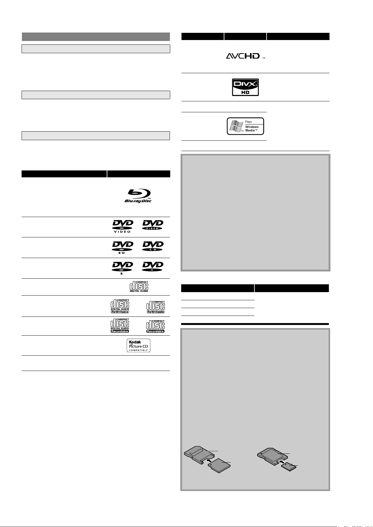
Readable cards Playable files / data
SD Memory Card (8MB - 2GB) AVCHD, MP3, Windows Media™
Audio, JPEG, Picture-in-picture
commentary, subtitles or other
extras for BD-ROM ver. 2 (Profile
2.0/ Profile 1.1)
SDHC Memory Card (4GB - 8GB)
miniSD Card (8MB - 2GB)
microSD Card (8MB - 2GB)
Note for SD Memory Cards
• Do not remove the SD Memory Card or turn the unit to the
standby mode while the contents of the card is in playback. It
may result in malfunction or loss of the card’s data.
• Please keep the SD Memory Cards in their cases when you are
not using them.
• Do not try to open or modify the card.
• Do not touch the terminal surface with your fingers or any
metals.
• Do not attach additional labels or stickers to cards.
• Do not remove the label of the SD Memory Cards.
• This unit supports SD Memory Card with FAT12/FAT16 file
system, and SDHC Memory Card with FAT32 file system.
• This unit may not read the SD Memory Cards formatted on
computer. If that is the case, please reformat the SD Memory
Cards on this unit and try again.
• This unit does not support mini SDHC and micro SDHC
Memory Card.
• For miniSD Card and microSD Card adapter is necessary.
• Portions of this product are protected under copyright law
and are provided under license by ARIS/SOLANA/4C.
miniSD Card
Adapter
miniSD Card
microSD Card
Adapter
microSD Card
Introduction Introduction
Playable files Logos Media
AVCHD
DVD-RW/-R
SD Memory Card
(including SDHC)
miniSD Card
microSD Card
DivX
®
BD-RE/-R
DVD-RW/-R
CD-RW/-R
MP3
BD-RE/-R
DVD-RW/-R
CD-RW/-R
SD Memory Card
(including SDHC)
miniSD Card
microSD Card
Windows Media™
Audio
JPEG
Note
• ABOUT DIVX VIDEO: DivX® is a digital video format created by
DivX, Inc. This is an official Divx Certified device that plays
DivX video. Visit www.divx.com for more information and
software tools to convert your files into DivX video.
• ABOUT DIVX VIDEO-ON-DEMAND: This DivX Certified
®
device
must be registered in order to play DivX Video-on-Demand
(VOD) content. To generate the registration code, locate the
DivX VOD section in the device setup menu. Go to
vod.divx.com with this code to complete the registration
process and learn more about DivX VOD.
• Discs containing the DivX® files with the DivX®GMC (Global
Motion Compensation) playback feature, which is DivX
®
supplemental function, cannot be played back on this unit.
• This unit cannot play back the disc contents protected by
Windows Media™ Digital Rights Management (DRM).
• “WMA” (Windows Media™ Audio) is an audio codec
developed by Microsoft® in the United States of America.
—
—
Readable cards Playable files / data
SD Memory Card (8MB - 2GB) AVCHD, MP3, Windows Media™
SDHC Memory Card (4GB - 8GB)
miniSD Card (8MB - 2GB)
microSD Card (8MB - 2GB)
Note for SD Memory Cards
• Do not remove the SD Memory Card or turn the unit to the
standby mode while the contents of the card is in playback. It
may result in malfunction or loss of the card’s data.
• Please keep the SD Memory Cards in their cases when you are
not using them.
• Do not try to open or modify the card.
• Do not touch the terminal surface with your fingers or any
metals.
• Do not attach additional labels or stickers to cards.
• Do not remove the label of the SD Memory Cards.
• This unit supports SD Memory Card with FAT12/FAT16 file
system, and SDHC Memory Card with FAT32 file system.
• This unit may not read the SD Memory Cards formatted on
computer. If that is the case, please reformat the SD Memory
Cards on this unit and try again.
• This unit does not support mini SDHC and micro SDHC
Memory Card.
• For miniSD Card and microSD Card adapter is necessary.
• Portions of this product are protected under copyright law
and are provided under license by ARIS/SOLANA/4C.
miniSD Card
Adapter
miniSD Card
Disc Handling
• Handle the discs so that fingerprints and dust do not adhere to
the surfaces of the discs.
• Always store the disc in its protective case when it is not used.
Playable files Logos Media
DVD-RW/-R
SD Memory Card
AVCHD
(including SDHC)
miniSD Card
microSD Card
• Note that discs with special shapes cannot be played on this
product. Do not attempt to play back such discs, as they may
damage the unit.
Cleaning Discs
• When a disc becomes dirty, clean it with a cleaning cloth. Wipe
the disc from the center to out. Do not wipe in a circular motion.
• Do not use solvents such as benzine, thinner, commercially
available cleaners, detergent, abrasive cleaning agents or
antistatic spray intended for analog records.
Playable Discs and Files
This unit is compatible to play back the following discs.
To play back a BD or DVD, make sure that it meets the
®
DivX
MP3
Windows Media™
Audio
JPEG
—
—
BD-RE/-R
DVD-RW/-R
CD-RW/-R
BD-RE/-R
DVD-RW/-R
CD-RW/-R
SD Memory Card
(including SDHC)
miniSD Card
microSD Card
requirements for region codes and color systems as described on
page 5. You can play back discs that have the following logos on
the disc. Other disc types are not guaranteed to play back.
Playable discs Logos
Blu-ray Disc
- BD-Video
- BD-RE (ver.2.1)
(Recorded in BDMV format)
- BD-R (ver.1.1/1.2/1.3)
(Recorded in BDMV format)
(Unclosed discs may not be played back.)
DVD-Video
Note
• ABOUT DIVX VIDEO: DivX® is a digital video format created by
DivX, Inc. This is an official Divx Certified device that plays
DivX video. Visit www.divx.com for more information and
software tools to convert your files into DivX video.
• ABOUT DIVX VIDEO-ON-DEMAND: This DivX Certified
must be registered in order to play DivX Video-on-Demand
(VOD) content. To generate the registration code, locate the
DivX VOD section in the device setup menu. Go to
vod.divx.com with this code to complete the registration
process and learn more about DivX VOD.
• Discs containing the DivX® files with the DivX®GMC (Global
Motion Compensation) playback feature, which is DivX
®
device
®
supplemental function, cannot be played back on this unit.
DVD-RW (Finalized discs only)
• This unit cannot play back the disc contents protected by
Windows Media™ Digital Rights Management (DRM).
• “WMA” (Windows Media™ Audio) is an audio codec
DVD-R
DVD-R DL
CD-DA (audio CD)
CD-RW
CD-R
Kodak Picture CD
(Finalized discs only)
DTS-CD (5.1 Music Disc)
—
developed by Microsoft® in the United States of America.
Readable cards Playable files / data
SD Memory Card (8MB - 2GB) AVCHD, MP3, Windows Media™
SDHC Memory Card (4GB - 8GB)
miniSD Card (8MB - 2GB)
microSD Card (8MB - 2GB)
Note for SD Memory Cards
• Do not remove the SD Memory Card or turn the unit to the
standby mode while the contents of the card is in playback. It
Audio, JPEG, Picture-in-picture
commentary, subtitles or other
extras for BD-ROM ver. 2 (Profile
2.0/ Profile 1.1)
may result in malfunction or loss of the card’s data.
• Please keep the SD Memory Cards in their cases when you are
not using them.
• Do not try to open or modify the card.
• Do not touch the terminal surface with your fingers or any
metals.
• Do not attach additional labels or stickers to cards.
• Do not remove the label of the SD Memory Cards.
• This unit supports SD Memory Card with FAT12/FAT16 file
system, and SDHC Memory Card with FAT32 file system.
• This unit may not read the SD Memory Cards formatted on
computer. If that is the case, please reformat the SD Memory
Cards on this unit and try again.
• This unit does not support mini SDHC and micro SDHC
Memory Card.
• For miniSD Card and microSD Card adapter is necessary.
miniSD Card
Adapter
miniSD Card
microSD Card
Adapter
microSD Card
• Portions of this product are protected under copyright law
and are provided under license by ARIS/SOLANA/4C.
2
Page 5
To specify for which media type each function is, we put the
following symbols at the beginning of each item to operate.
If you do not find any of the symbols listed above under the
function heading, the operation is applicable to all media.
Symbols Used in this User Guide
Symbol Description
Description refers to BD-Video and BD-RE (ver. 2.1)/
BD-R (ver.1.1/1.2/1.3) recorded in BDMV format
Description refers to DVD-Video and DVD-RW/-R
recorded in video mode
Description refers to DVD-RW/-R recorded in VR mode
Description refers to audio CD and DTS-CD
Description refers to DVD-RW/-R and SD Card with
AVCHD files
Description refers to BD-RE/-R, DVD-RW/-R and
CD-RW/-R with DivX
®
files
Description refers to BD-RE/-R, DVD-RW/-R, CD-RW/-R
and SD Memory Card with MP3 files
Description refers to BD-RE/-R, DVD-RW/-R, CD-RW/-R
and SD Memory Card with Windows Media™ Audio
files
Description refers to BD-RE/-R, DVD-RW/-R, CD-RW/-R
and SD Memory Card with JPEG files
BD-V
DVD-V
DVD-VR
CD
AVCHD
DivX
®
MP3
WMA
JPEG
About the button names in this explanation
< > : Buttons on the main unit
[ ] : Buttons on the remote control
Button name only:
Buttons on the main unit and remote control
This unit has been designed to play back BD with
region A and DVD-Video with region 1. You cannot
play back BD or DVD-Video that are labeled for other
regions. Look for the symbols on the right on your BD
or DVD-Video. If these region symbols do not appear
on your BD or DVD-Video, you cannot play back the
disc in this unit. The letter or number inside the
globe refers to region of the world. A BD or
DVD-Video labeled for a specific region can only play
back on the unit with the same region code.
To specify for which media type each function is, we put the
following symbols at the beginning of each item to operate.
If you do not find any of the symbols listed above under the
function heading, the operation is applicable to all media.
Region Codes
BD-Video
DVD-Video
Symbols Used in this User Guide
Symbol Description
Description refers to BD-Video and BD-RE (ver. 2.1)/
BD-R (ver.1.1/1.2/1.3) recorded in BDMV format
Description refers to DVD-Video and DVD-RW/-R
recorded in video mode
Description refers to DVD-RW/-R recorded in VR mode
Description refers to audio CD and DTS-CD
Description refers to DVD-RW/-R and SD Card with
AVCHD files
Description refers to BD-RE/-R, DVD-RW/-R and
CD-RW/-R with DivX
®
files
Description refers to BD-RE/-R, DVD-RW/-R, CD-RW/-R
and SD Memory Card with MP3 files
Description refers to BD-RE/-R, DVD-RW/-R, CD-RW/-R
and SD Memory Card with Windows Media™ Audio
files
Description refers to BD-RE/-R, DVD-RW/-R, CD-RW/-R
and SD Memory Card with JPEG files
BD-V
DVD-V
DVD-VR
CD
AVCHD
DivX
®
MP3
WMA
JPEG
About the button names in this explanation
< > : Buttons on the main unit
[ ] : Buttons on the remote control
Button name only:
Buttons on the main unit and remote control
To specify for which media type each function is, we put the
following symbols at the beginning of each item to operate.
Symbols Used in this User Guide
Symbol Description
Description refers to BD-Video and BD-RE (ver. 2.1)/
BD-R (ver.1.1/1.2/1.3) recorded in BDMV format
Description refers to DVD-Video and DVD-RW/-R
recorded in video mode
Description refers to DVD-RW/-R recorded in VR mode
Description refers to audio CD and DTS-CD
BD-V
DVD-V
DVD-VR
CD
Introduction Introduction
This unit uses NTSC, so BD or DVD you play back must be recorded
This unit has been designed to play back BD with
region A and DVD-Video with region 1. You cannot
play back BD or DVD-Video that are labeled for other
regions. Look for the symbols on the right on your BD
or DVD-Video. If these region symbols do not appear
on your BD or DVD-Video, you cannot play back the
disc in this unit. The letter or number inside the
globe refers to region of the world. A BD or
DVD-Video labeled for a specific region can only play
back on the unit with the same region code.
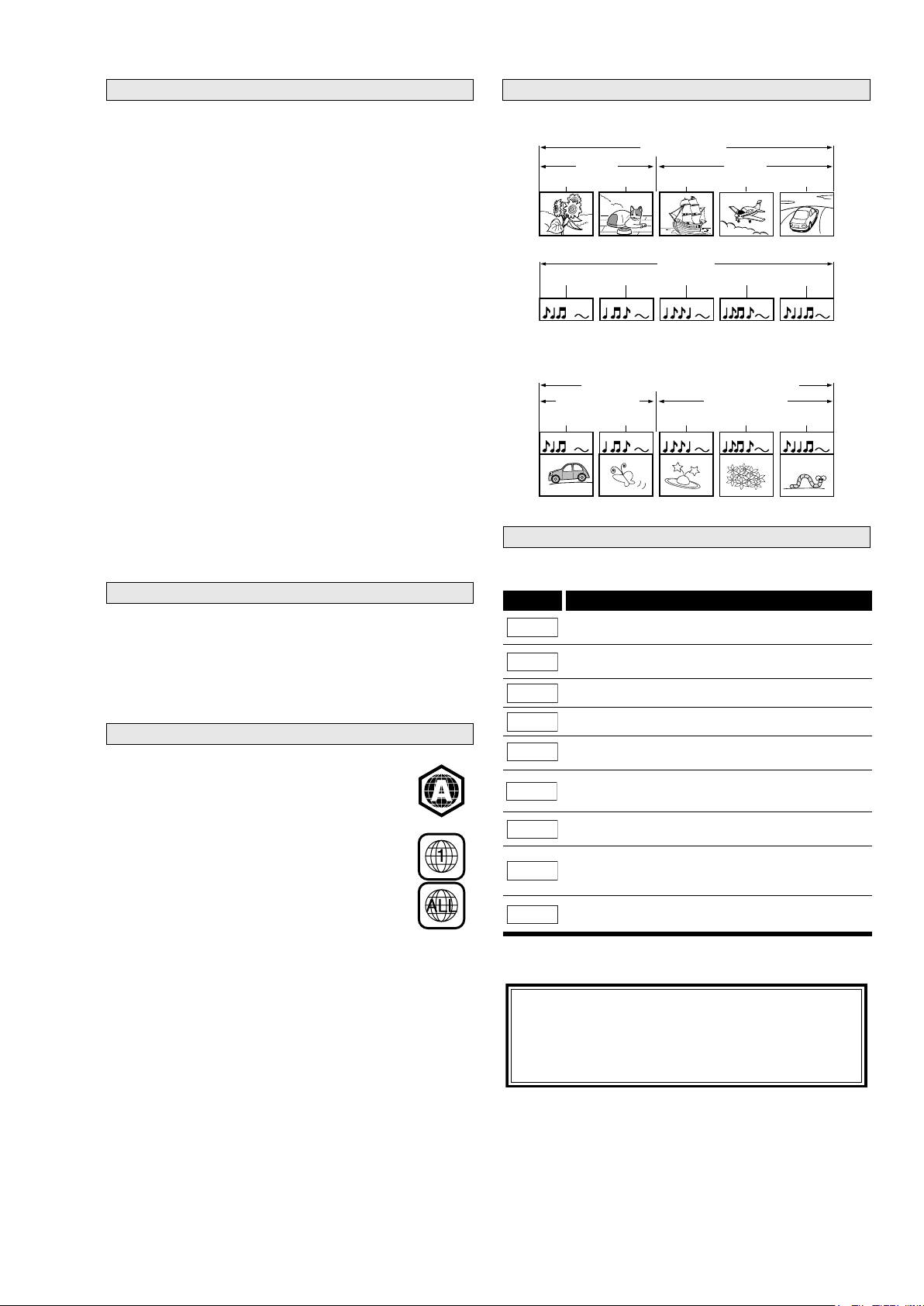
The contents of disc are generally divided into titles. Titles may be
further subdivided into chapters.
To specify for which media type each function is, we put the
following symbols at the beginning of each item to operate.
If you do not find any of the symbols listed above under the
function heading, the operation is applicable to all media.
Unplayable Discs
Region Codes
Structure of Disc/SD Memory Card Contents
BD-Video
DVD-Video
title 1 title 2
chapter 1 chapter 2 chapter 1 chapter 2 chapter 3
BD/DVD/AVCHD
audio CD
Audio CD
track 1 track 2 track 3 track 4 track 5
Audio CDs are divided into tracks.
MP3, WMA, JPEG, DivX®
group(folder)1 group(folder)2
DivX®/MP3/Windows Media™ Audio/JPEG
folder (group) 1 folder (group) 2
file (track) 1 file (track) 2 file (track) 3 file (track) 4 file (track) 5
Data discs or SD Memory Cards containing DivX® (in discs only)/
MP3/Windows Media™ Audio/JPEG are divided into folders, and
the folders are subdivided into files.
Symbols Used in this User Guide
Symbol Description
Description refers to BD-Video and BD-RE (ver. 2.1)/
BD-R (ver.1.1/1.2/1.3) recorded in BDMV format
Description refers to DVD-Video and DVD-RW/-R
recorded in video mode
Description refers to DVD-RW/-R recorded in VR mode
Description refers to audio CD and DTS-CD
Description refers to DVD-RW/-R and SD Card with
AVCHD files
Description refers to BD-RE/-R, DVD-RW/-R and
CD-RW/-R with DivX
Description refers to BD-RE/-R, DVD-RW/-R, CD-RW/-R
and SD Memory Card with MP3 files
Description refers to BD-RE/-R, DVD-RW/-R, CD-RW/-R
and SD Memory Card with Windows Media™ Audio
files
Description refers to BD-RE/-R, DVD-RW/-R, CD-RW/-R
and SD Memory Card with JPEG files
BD-V
DVD-V
DVD-VR
CD
AVCHD
DivX
®
MP3
WMA
JPEG
About the button names in this explanation
< > : Buttons on the main unit
[ ] : Buttons on the remote control
Button name only:
Buttons on the main unit and remote control
The following discs will not play back on this unit.
• BD-RE (ver.1.0) (BD-disc with cartridge)
• BD-RE (ver.2.1) (Recorded in BDAV format)
• BD-R (ver.1.1/1.2/1.3) (Recorded in BDAV format)
• BD that contains AVCHD files
• Multi-session burn BD/DVD with DivX
• Multi-session burn BD-RE/-R with MP3/Windows Media™ Audio/
JPEG files
• BD/DVD hybrid disc (e.g. Total Hi Def hybrid disc)
• BD-Video that does not include “A” on its region code.
• DVD-Video that does not include either “1” nor “ALL” on its
region code.
• DVD-ROM/RAM (For DVD-ROM discs, data files in DivX
5.x and 6.x can be played)
• DVD-RW/-R recorded in non-compatible recording format
• CD-ROM (Data files in DivX
• CDV (Only the audio part can be played)
• CD-G (Only the audio signals can be output)
• Compact Disc-Interactive (CD-I)
• Video Single Disc (VSD)
• Video CD, Super Video CD
• Super audio CD (Only the sound on the CD layer can be heard.
The sound on the high-density super audio CD layer cannot be
heard.)
• DVD-Audio
• HD DVD
• Disc with recording area less than 55mm in diameter
• Unauthorized disc (Pirated disc)
• Unfinalized disc
®
3.11, 4.x, 5.x and 6.x can be played)
®
files
®
3.11, 4.x,
Structure of Disc/SD Memory Card Contents
The contents of disc are generally divided into titles. Titles may be
further subdivided into chapters.
BD/DVD/AVCHD
title 1 title 2
chapter 1 chapter 2 chapter 1 chapter 2 chapter 3
Audio CDs are divided into tracks.
track 1 track 2 track 3 track 4 track 5
Data discs or SD Memory Cards containing DivX® (in discs only)/
MP3/Windows Media™ Audio/JPEG are divided into folders, and
the folders are subdivided into files.
DivX®/MP3/Windows Media™ Audio/JPEG
folder (group) 1 folder (group) 2
group(folder)1 group(folder)2
file (track) 1 file (track) 2 file (track) 3 file (track) 4 file (track) 5
Audio CD
audio CD
MP3, WMA, JPEG, DivX®
Color Systems
BD and DVD are recorded in different color systems throughout
the world. The most common color system is NTSC (which is used
primarily in the United States and Canada).
in the NTSC system. You cannot play back BD or DVD recorded in
other color systems.
Region Codes
This unit has been designed to play back BD with
region A and DVD-Video with region 1. You cannot
play back BD or DVD-Video that are labeled for other
regions. Look for the symbols on the right on your BD
or DVD-Video. If these region symbols do not appear
on your BD or DVD-Video, you cannot play back the
disc in this unit. The letter or number inside the
globe refers to region of the world. A BD or
DVD-Video labeled for a specific region can only play
back on the unit with the same region code.
BD-Video
DVD-Video
3
Page 6
2.SERVICEHINTSANDTOOLS
SERVICE HINTS
SERVICE TOOLS
Audio signals disc 4822 397 30184
Disc without errors (SBC444)+
Disc with DO errors, black spots and fingerprints (SBC444A) 4822 397 30245
Disc (65 min 1kHz) without no pause 4822 397 30155
Max. diameter disc (58.0 mm) 4822 397 60141
Torx screwdrivers
Set (straight) 4822 395 50145
Set (square) 4822 395 50132
13th order filter 4822 395 30204
DVD test disc (PAL) 4822 397 10131
DVD test disc (NTSC) ALMEDIO TDV-540
4
Page 7

3.WARNINGANDLASERSAFETYINSTRUCTION
GB
WARNING
All ICs and many other semi-conductors are
susceptible to electrostatic discharges (ESD).
Careless handling during repair can reduce
life drastically.
When repairing, make sure that you are
connected with the same potential as the
mass of the set via a wrist wrap with
resistance.
Keep components and tools also at this
potential.
F
ATTENTION
D
WARNUNG
I
WAARSCHUWING
AVVERTIMENTO
NL
Alle IC’s en vele andere halfgeleiders zijn
gevoelig voor elektrostatische ontladingen
(ESD).
Onzorgvuldig behandelen tijdens reparatie
kan de levensduur drastisch doen
verminderen.
Zorg ervoor dat u tijdens reparatie via een
polsband met weerstand verbonden bent met
hetzelfde potentiaal als de massa van het
apparaat.
Houd componenten en hulpmiddelen ook op
ditzelfde potentiaal.
Tous les IC et beaucoup d’autres semiconducteurs sont sensibles aux décharges
statiques (ESD).
Leur longévité pourrait être considérablement
écourtée par le fait qu’aucune précaution
n’est prise a leur manipulation.
Lors de réparations, s’assurer de bien être
relié au même potentiel que la masse de
l’appareil et enfiler le bracelet serti d’une
résistance de sécurité.
Veiller a ce que les composants ainsi que les
outils que l’on utilise soient également a ce
potentiel.
GB
Safety regulations require that the set be restored to its original condition
and that parts which are identical with those specified be used.
NL
Veiligheidsbepalingen vereisen, dat het apparaat in zijn oorspronkelijke
toestand wordt terug gebracht en dat onderdelen, identiek aan de
gespecifieerde worden toegepast.
Alle IC und viele andere Halbleiter sind
empfindlich gegen elektrostatische
Entladungen (ESD).
Unsorgfältige Behandlung bei der Reparatur
kann die Lebensdauer drastisch vermindern.
Sorgen sie dafür, das Sie im Reparaturfall
über ein Pulsarmband mit Widerstand mit
dem Massepotential des Gerätes verbunden
sind.
Halten Sie Bauteile und Hilfsmittel ebenfalls
auf diesem Potential.
D
Bei jeder Reparatur sind die geltenden Sicherheitsvorschriften zu beachten.
Der Originalzustand des Gerats darf nicht verandert werden.
Fur Reparaturen sind Original-Ersatzteile zu verwenden.
I
Le norme di sicurezza esigono che l’apparecchio venga rimesso nelle
condizioni originali e che siano utilizzati pezzi di ricambiago idetici a quelli
specificati.
Tutti IC e parecchi semi-conduttori sono
sensibili alle scariche statiche (ESD).
La loro longevita potrebbe essere fortemente
ridatta in caso di non osservazione della piu
grande cauzione alla loro manipolazione.
Durante le riparazioni occorre quindi essere
collegato allo stesso potenziale che quello
della massa dell’apparecchio tramite un
braccialetto a resistenza.
Assicurarsi che i componenti e anche gli
utensili con quali si lavora siano anche a
questo potenziale.
F
“Pour votre sécurité, ces documents
doivent être utilisés par des
spécialistes agrées, seu ls habilités à
réparer votre appareil en panne.”
Les normes de sécurité exigent que l’appareil soit remis a l’état d’origine et
que soient utilisées les pièces de rechange identiques à celles spécifiées.
LASER SAFETY
This unit employs a laser. Only a qualified service person should remove the cover or attempt to service this
device, due to possible eye injury.
USE OF CONTROLS OR ADJUSTMENTS OR PERFORMANCE OF PROCEDURE OTHER THAN THOSE
SPECIFIED HEREIN MAY RESULT IN HAZARDOUS RADIATION EXPOSURE.
AVOID DIRECT EXPOSURE TO BEAM
WARNING
The use of optical instruments with this product will increase eye hazard.
Repair handling should take place as much as possible with a disc loaded inside the player
WARNING LOCATION: INSIDE ON LASER COVERSHIELD
CAUTION VISIBLE AND INVISIBLE LASER RADIATION WHEN OPEN AVOID EXPOSURE TO BEAM
ADVARSEL SYNLIG OG USYNLIG LASERSTRÅLING VED ÅBNING UNDGÅ UDS
ADVARSEL SYNLIG OG USYNLIG LASERSTRÅLING NÅR DEKSEL Å PNES UNNGÅ EKSPONERING FOR STRÅLEN
VARNING SYNLIG OCH OSYNLIG LASERSTRÅLNING NÄR DENNA DEL ÄR ÖPPNAD BETRAKTA EJ STRÅLEN
VARO! AVATT AESSA OLET ALTTIINA NÄKYVÄLLE JA NÄKYMÄTTÖMÄLLE LASER SÄTEILYLLE. ÄLÄ KATSO SÄTEESEEN
VORSICHT SICHTBARE UND UNSICHTBARE LASERSTRAHLUNG WENN ABDECKUNG GEÖFFNET NICHT DEM STRAHL AUSSETSEN
DANGER VISIBLE AND INVISIBLE LASER RADIATION WHEN OPEN AVOID DIRECT EXPOSURE TO BEAM
ATTENTION RAYONNEMENT LASER VISIBLE ET INVISIBLE EN CAS D'OUVERTURE EXPOSITION DANGEREUSE AU FAISCEAU
Æ
TTELSE FOR STRÅLING
5
030804ecm
Page 8
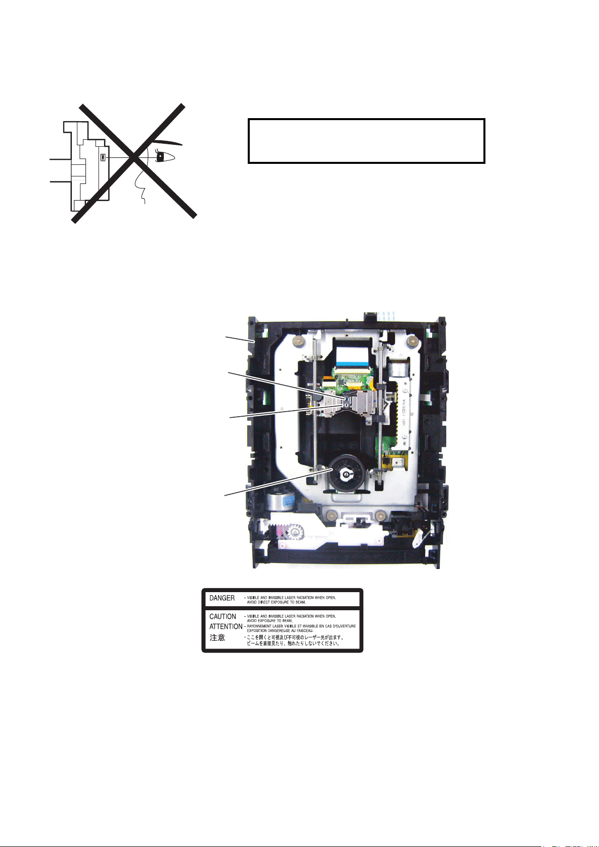
4.LASERBEAMSAFETYPRECAUTIONS
LASER BEAM SAFETY PRECAUTIONS
This BD player uses a pickup that emits a laser beam.
Do not look directly at the laser beam coming
The laser beam is emitted from the location shown in the figure. When checking the laser diode, be sure to keep
your eyes at least 30 cm away from the pickup lens when the diode is turned on. Do not look directly at the laser
beam.
CAUTION: Use of controls and adjustments, or doing procedures other than those specified herein, may result in
hazardous radiation exposure.
Drive Mechanism Assembly
from the pickup or allow it to strike against your
skin.
Laser Beam Radiation
Laser Pickup
Turntable
Location: Inside Top of BD mechanism.
6
Page 9

5.IMPORTANTSAFETYPRECAUTIONS
IMPORTANT SAFETY PRECAUTIONS
Product Safety Notice
Some electrical and mechanical parts have special
safety-related characteristics which are often not
evident from visual inspection, nor can the protection
they give necessarily be obtained by replacing them
with components rated for higher voltage, wattage,
etc. Parts that have special safety characteristics are
identified by a ! on schematics and in parts lists. Use
of a substitute replacement that does not have the
same safety characteristics as the recommended
replacement part might create shock, fire, and/or other
hazards. The Product’s Safety is under review
continuously and new instructions are issued
whenever appropriate. Prior to shipment from the
factory, our products are carefully inspected to confirm
with the recognized product safety and electrical
codes of the countries in which they are to be sold.
However, in order to maintain such compliance, it is
equally important to implement the following
precautions when a set is being serviced.
I. Also check areas surrounding repaired locations.
J. Be careful that foreign objects (screws, solder
droplets, etc.) do not remain inside the set.
K. When connecting or disconnecting the internal
connectors, first, disconnect the AC plug from the
AC outlet.
Precautions during Servicing
A. Parts identified by the ! symbol are critical for
safety. Replace only with part number specified.
B. In addition to safety, other parts and assemblies
are specified for conformance with regulations
applying to spurious radiation. These must also be
replaced only with specified replacements.
Examples: RF converters, RF cables, noise
blocking capacitors, and noise blocking filters, etc.
C. Use specified internal wiring. Note especially:
1) Wires covered with PVC tubing
2) Double insulated wires
3) High voltage leads
D. Use specified insulating materials for hazardous
live parts. Note especially:
1) Insulation tape
2) PVC tubing
3) Spacers
4) Insulators for transistors
E. When replacing AC primary side components
(transformers, power cord, etc.), wrap ends of
wires securely about the terminals before
soldering.
F. Observe that the wires do not contact heat
producing parts (heat sinks, oxide metal film
resistors, fusible resistors, etc.).
G. Check that replaced wires do not contact sharp
edges or pointed parts.
H. When a power cord has been replaced, check that
5 - 6 kg of force in any direction will not loosen it.
7
Page 10
Safety Check after Servicing
Examine the area surrounding the repaired location for damage or deterioration. Observe that screws, parts, and
wires have been returned to their original positions. Afterwards, do the following tests and confirm the specified
values to verify compliance with safety standards.
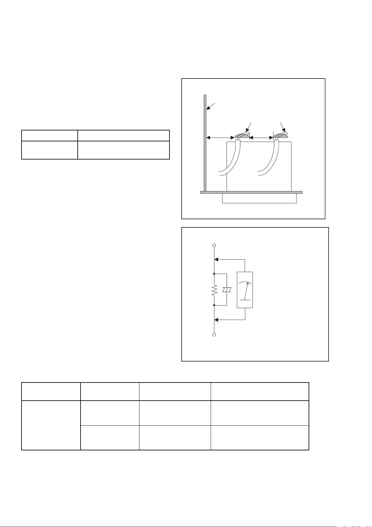
1. Clearance Distance
When replacing primary circuit components, confirm
specified clearance distance (d) and (d’) between
soldered terminals, and between terminals and
surrounding metallic parts. (See Fig. 1)
Table 1: Ratings for selected area
Chassis or Secondary Conductor
Primary Circuit
AC Line Voltage Clearance Distance (d), (d’)
120 V
Note: This table is unofficial and for reference only. Be
sure to confirm the precise values.
≥ 3mm(d)
≥ 4mm(d’)
2. Leakage Current Test
Confirm the specified (or lower) leakage current
between B (earth ground, power cord plug prongs) and
externally exposed accessible parts (RF terminals,
antenna terminals, video and audio input and output
terminals, microphone jacks, earphone jacks, etc.) is
lower than or equal to the specified value in the table
below.
Measuring Method (Power ON):
Insert load Z between B (earth ground, power cord plug
prongs) and exposed accessible parts. Use an AC
voltmeter to measure across the terminals of load Z.
See Fig. 2 and the following table.
d' d
Exposed Accessible Part
Z
One side of
B
Power Cord Plug Prongs
Fig. 1
AC Voltmeter
(High Impedance)
Table 2: Leakage current ratings for selected areas
AC Line Voltage Load Z Leakage Current (i)
2kΩ RES.
Connected in
parallel
120 V
50kΩ RES.
Connected in
parallel
Note:This table is unofficial and for reference only. Be sure to confirm the precise values.
i≤0.7mA AC Peak
i≤2mA DC
i≤0.7mA AC Peak
i≤2mA DC
8
One side of power cord plug
prongs (B) to:
RF or
Antenna terminals
A/V Input, Output
Fig. 2
Page 11
6.STANDARDNOTESFORSERVICING
STANDARD NOTES FOR SERVICING
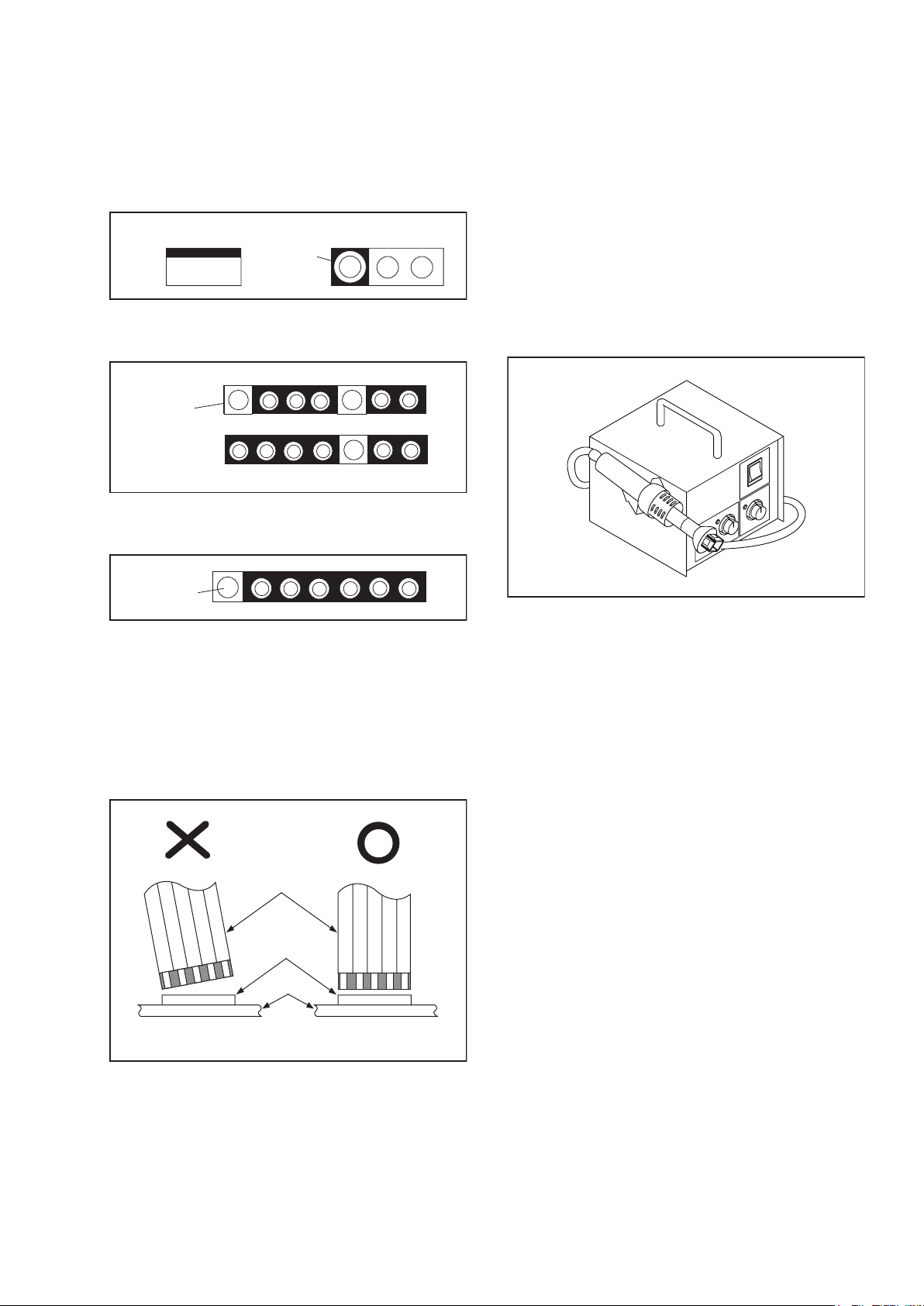
Circuit Board Indications
Pb (Lead) Free Solder
1. The output pin of the 3 pin Regulator ICs is
indicated as shown.
Top View
Out
2. For other ICs, pin 1 and every fifth pin are
indicated as shown.
In
Pin 1
3. The 1st pin of every male connector is indicated as
shown.
Pin 1
Instructions for Connectors
1. When you connect or disconnect the FFC (Flexible
Foil Connector) cable, be sure to first disconnect
the AC cord.
2. FFC (Flexible Foil Connector) cable should be
inserted parallel into the connector, not at an
angle.
FFC Cable
Input
Connector
CBA
Bottom View
5
10
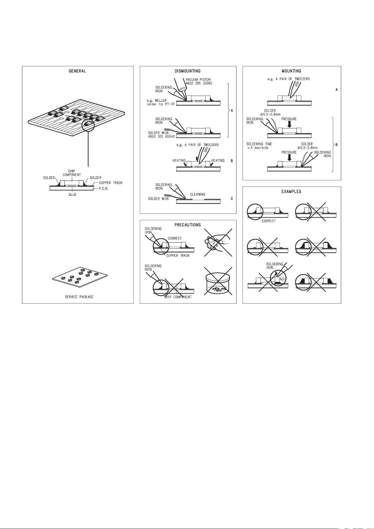
When soldering, be sure to use the Pb free solder.
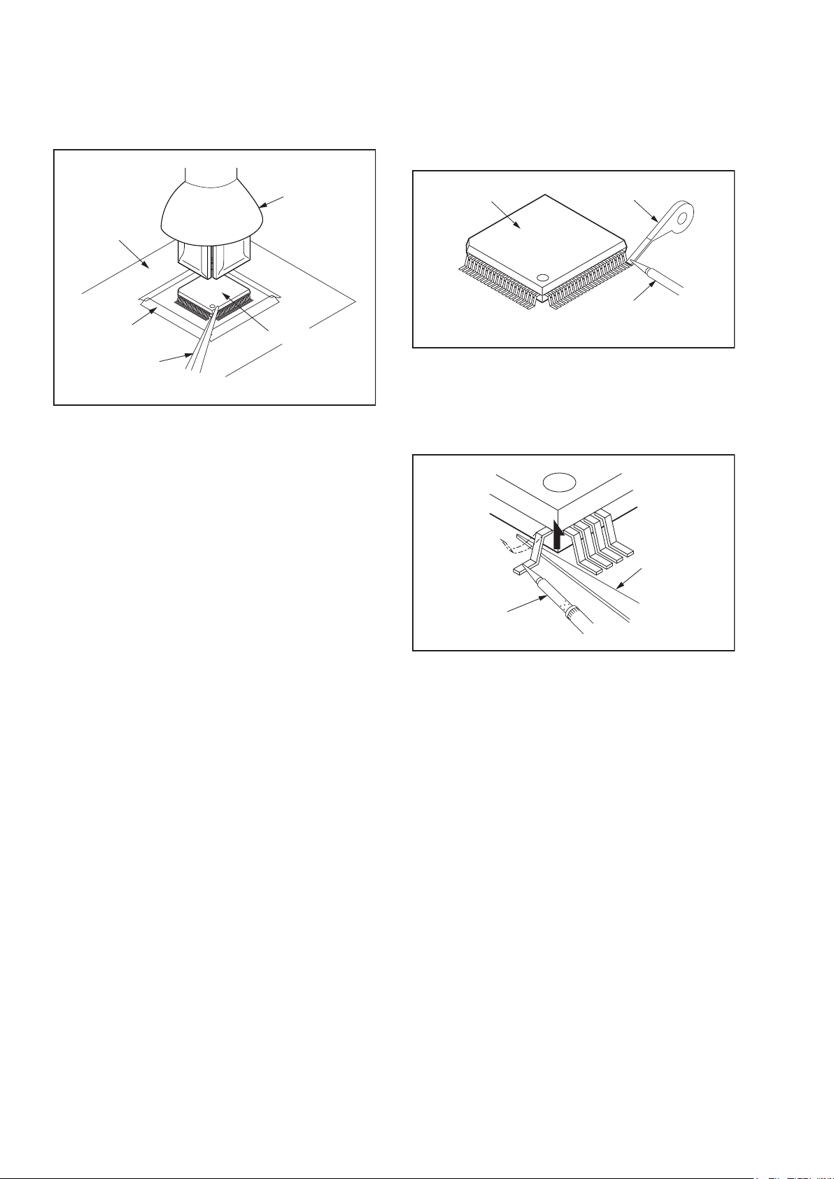
How to Remove / Install Flat Pack-IC
1. Removal
With Hot-Air Flat Pack-IC Desoldering Machine:
1. Prepare the hot-air flat pack-IC desoldering
machine, then apply hot air to the Flat Pack-IC
(about 5 to 6 seconds). (Fig. S-1-1)
Fig. S-1-1
2. Remove the flat pack-IC with tweezers while
applying the hot air.
3. Bottom of the flat pack-IC is fixed with glue to the
CBA; when removing entire flat pack-IC, first apply
soldering iron to center of the flat pack-IC and heat
up. Then remove (glue will be melted). (Fig. S-1-6)
4. Release the flat pack-IC from the CBA using
tweezers. (Fig. S-1-6)
CAUTION:
1. The Flat Pack-IC shape may differ by models. Use
an appropriate hot-air flat pack-IC desoldering
machine, whose shape matches that of the Flat
Pack-IC.
2. Do not supply hot air to the chip parts around the
flat pack-IC for over 6 seconds because damage
to the chip parts may occur. Put masking tape
around the flat pack-IC to protect other parts from
damage. (Fig. S-1-2)
* Be careful to avoid a short circuit.
9
Page 12
3. The flat pack-IC on the CBA is affixed with glue, so
be careful not to break or damage the foil of each
pin or the solder lands under the IC when
removing it.
With Soldering Iron:
1. Using desoldering braid, remove the solder from
all pins of the flat pack-IC. When you use solder
flux which is applied to all pins of the flat pack-IC,
you can remove it easily. (Fig. S-1-3)
CBA
Masking
Tape
Tweezers
Hot-air
Flat Pack-IC
Desoldering
Machine
Flat Pack-IC
Fig. S-1-2
Flat Pack-IC
Desoldering Braid
Soldering Iron
Fig. S-1-3
2. Lift each lead of the flat pack-IC upward one by
one, using a sharp pin or wire to which solder will
not adhere (iron wire). When heating the pins, use
a fine tip soldering iron or a hot air desoldering
machine. (Fig. S-1-4)
Sharp
Pin
Fine Tip
Soldering Iron
Fig. S-1-4
3. Bottom of the flat pack-IC is fixed with glue to the
CBA; when removing entire flat pack-IC, first apply
soldering iron to center of the flat pack-IC and heat
up. Then remove (glue will be melted). (Fig. S-1-6)
4. Release the flat pack-IC from the CBA using
tweezers. (Fig. S-1-6)
10
Page 13
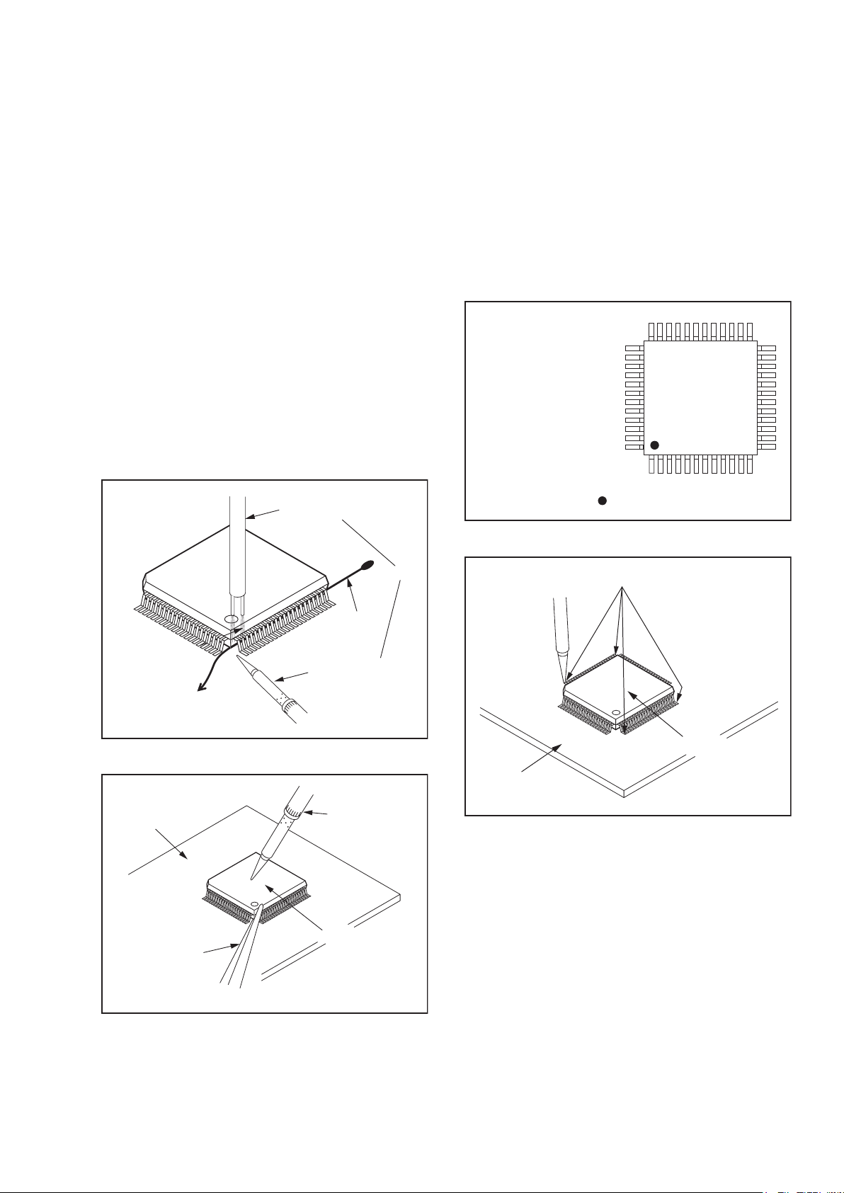
With Iron Wire:
1. Using desoldering braid, remove the solder from
all pins of the flat pack-IC. When you use solder
flux which is applied to all pins of the flat pack-IC,
you can remove it easily. (Fig. S-1-3)
2. Affix the wire to a workbench or solid mounting
point, as shown in Fig. S-1-5.
3. While heating the pins using a fine tip soldering
iron or hot air blower, pull up the wire as the solder
melts so as to lift the IC leads from the CBA
contact pads as shown in Fig. S-1-5.
4. Bottom of the flat pack-IC is fixed with glue to the
CBA; when removing entire flat pack-IC, first apply
soldering iron to center of the flat pack-IC and heat
up. Then remove (glue will be melted). (Fig. S-1-6)
5. Release the flat pack-IC from the CBA using
tweezers. (Fig. S-1-6)
Note: When using a soldering iron, care must be
taken to ensure that the flat pack-IC is not
being held by glue. When the flat pack-IC is
removed from the CBA, handle it gently
because it may be damaged if force is applied.
Hot Air Blower
2. Installation
1. Using desoldering braid, remove the solder from
the foil of each pin of the flat pack-IC on the CBA
so you can install a replacement flat pack-IC more
easily.
2. The “●” mark on the flat pack-IC indicates pin 1.
(See Fig. S-1-7.) Be sure this mark matches the
pin 1 on the PCB when positioning for installation.
Then presolder the four corners of the flat pack-IC.
(See Fig. S-1-8.)
3. Solder all pins of the flat pack-IC. Be sure that
none of the pins have solder bridges.
Example :
Pin 1 of the Flat Pack-IC
is indicated by a " " mark.
Fig. S-1-7
To Solid
Mounting Point
CBA
Tweezers
Iron Wire
Soldering Iron
Fig. S-1-5
Fine Tip
Soldering Iron
Flat Pack-IC
or
Presolder
Flat Pack-IC
CBA
Fig. S-1-8
Fig. S-1-6
11
Page 14
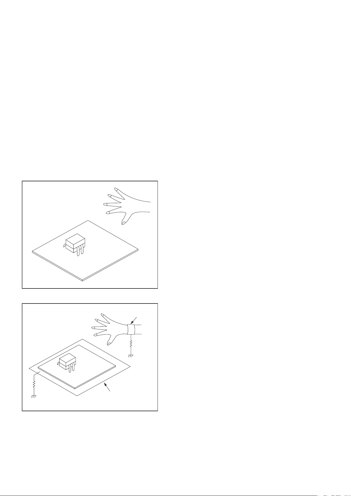
Instructions for Handling Semi-
conductors
Electrostatic breakdown of the semi-conductors may
occur due to a potential difference caused by
electrostatic charge during unpacking or repair work.
1. Ground for Human Body
Be sure to wear a grounding band (1 MΩ) that is
properly grounded to remove any static electricity that
may be charged on the body.
2. Ground for Workbench
Be sure to place a conductive sheet or copper plate
with proper grounding (1 MΩ) on the workbench or
other surface, where the semi-conductors are to be
placed. Because the static electricity charge on
clothing will not escape through the body grounding
band, be careful to avoid contacting semi-conductors
with your clothing.
<Incorrect>
<Correct>
1MΩ
CBA
Grounding Band
1MΩ
CBA
Conductive Sheet or
Copper Plate
12
Page 15
7.CABINETDISASSEMBLYINSTRUCTIONS
CABINET DISASSEMBLY INSTRUCTIONS
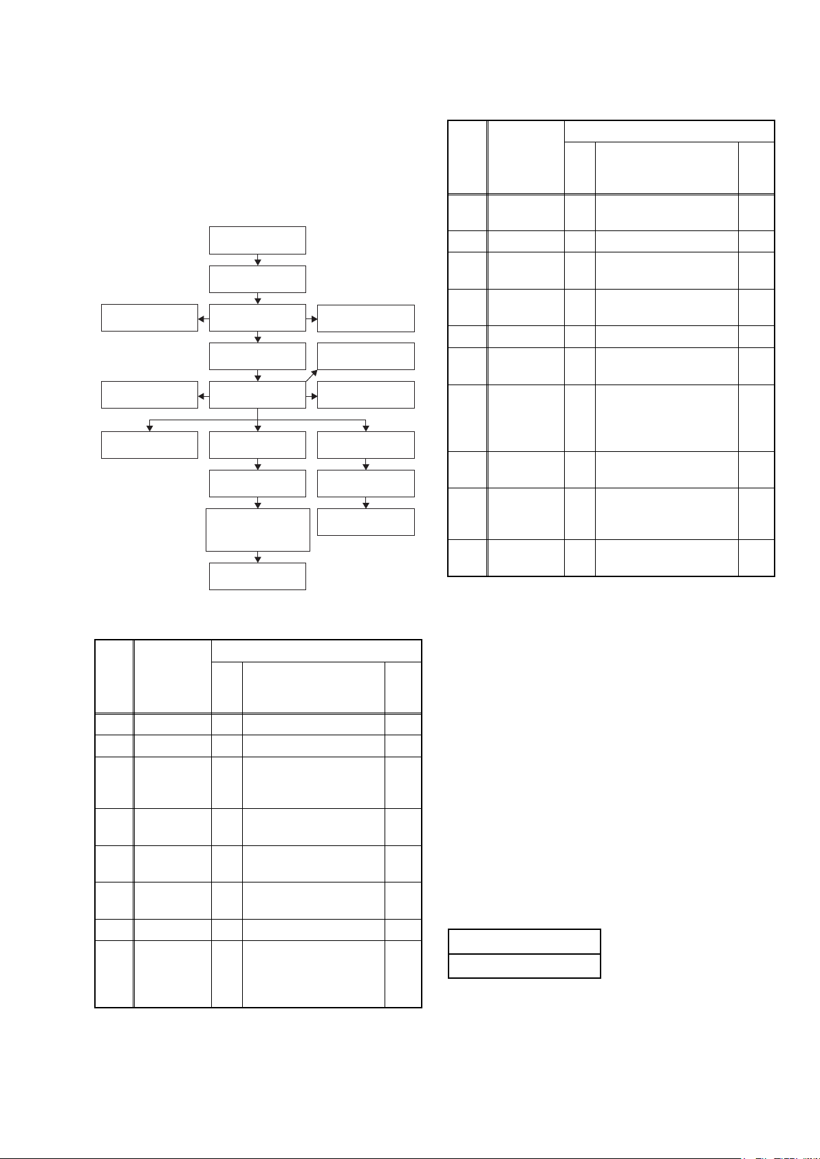
1. Disassembly Flowchart
This flowchart indicates the disassembly steps to gain
access to item(s) to be serviced. When reassembling,
follow the steps in reverse order. Bend, route, and
dress the cables as they were originally.
[5] Front B CBA
[11] RS232C
CBA
[12] Audio CBA
[1] Top Cover
[2] Tray Panel
[6] Front Bracket
[8] Rear Panel
[13] Video CBA
[14] AV PCB
Bracket
[15] BD Main CBA
& BD Mechanism
Assembly
[16] Loader
Bracket
2. Disassembly Method
ID/
Loc.
No.
[1] Top Cover D1 9(S-1) --[2] Tray Panel D2 --------------- 1
[3]
[4]
[5]
[6]
[7]
[8] Rear Panel D4
Part
Front
Assembly
Front A
CBA
Front B
CBA
Front
Bracket
SD CBA
Fig.
No.
D2
D2 *CN3001 ---
D2 --------------- ---
D3 7(S-5), (S-6) ---
D3 2(S-7), *CN5001 ---
[3] Front
Assembly
[4] Front A CBA
[10] Inlet CBA
[7] SD CBA
[17] Power
Supply CBA
[18] Power
Holder
Removal
Remove/*Unhook/
Unlock/Release/
Unplug/Desolder
*5(L-1), *3(L-2),
2(S-2), 3(S-3),
10(S-4), *CN2002
5(S-8), (S-9), 2(S-10),
(S-11), (S-12),
11(S-13), 2(S-14),
2(S-15), *CN1006
[9] Motor
DC Fan
Note
2
---
ID/
Loc.
No.
[9]
[10]
[11]
Part
Motor DC
Fan
Inlet CBA
RS232C
CBA
Fig.
No.
[12] Audio CBA D5
D4 --------------- ---
D4 *CN1001 ---
D4 *CN5501 ---
5(S-16), *CN2005,
*CN2007, *CN2008
Removal
Remove/*Unhook/
Unlock/Release/
Unplug/Desolder
Note
---
[13] Video CBA D6 4(S-17), *CN7101 ---
AV PCB
[14]
Bracket
D6 4(S-18) ---
BD Main
[15]
CBA & BD
Mechanism
4(S-19), *CN6001,
D6
*CN7601
Assembly
Loader
[16]
Bracket
D6 6(S-20) ---
Power
[17]
Supply
D7 3(S-21), 2(S-22) ---
CBA
Power
[18]
↓
(1)
Holder
↓
(2)
D7 3(S-23) ---
↓
(3)
↓
(4)
(5)
Note:
(1) Identification (location) No. of parts in the figures
(2) Name of the part
(3) Figure Number for reference
(4) Identification of parts to be removed, unhooked,
unlocked, released, unplugged, unclamped, or
desoldered.
P = Spring, L = Locking Tab, S = Screw,
CN = Connector
* = Unhook, Unlock, Release, Unplug, or Desolder
e.g. 2(S-2) = two Screws (S-2),
2(L-2) = two Locking Tabs (L-2)
(5) Refer to “Reference Notes.”
About tightening screws
When tightening screws, tighten them with the
following torque.
Torque
0.45 ± 0.05 N·m
3
↓
13
Page 16
Reference Note
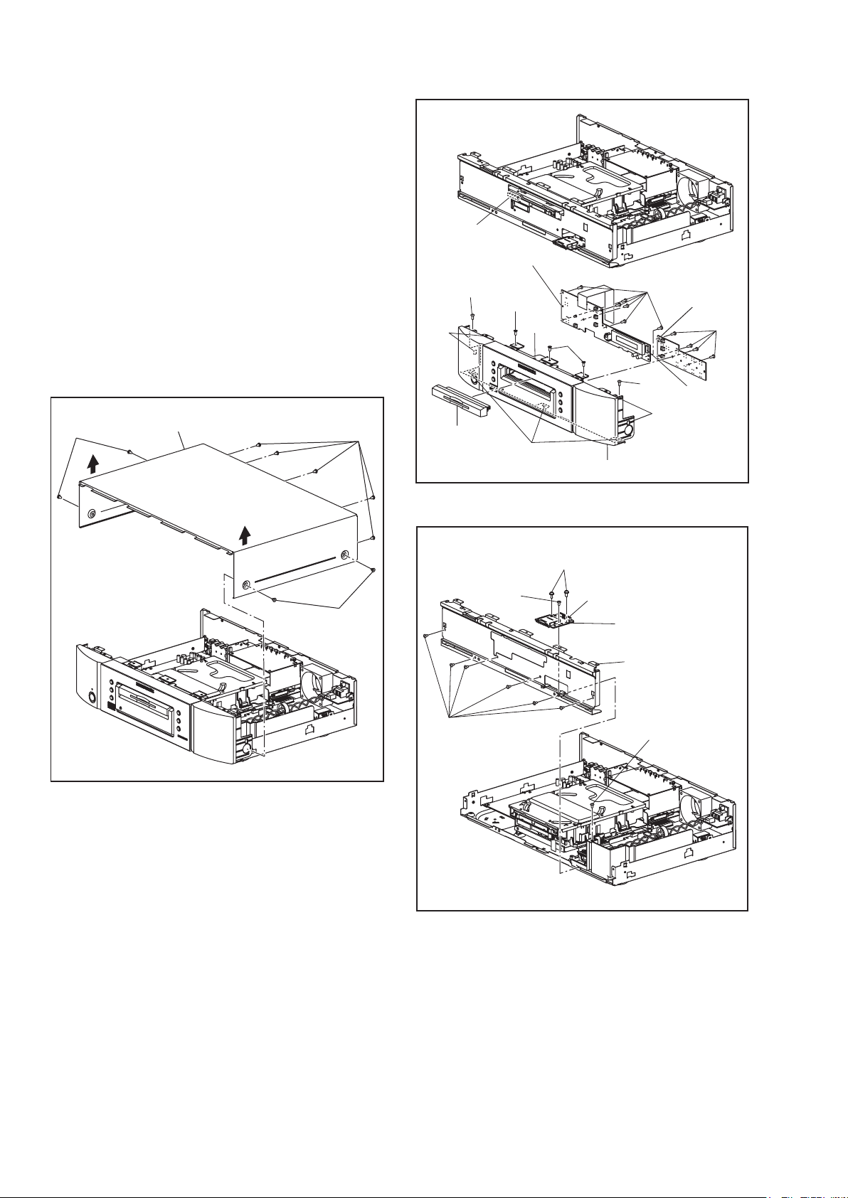
1. How to remove tray panel
1) Connect the wall plug to an AC outlet and press
the [ A] button to open the tray.
2) To lift up, the tray panel is removed.
3) Press the [ A] button again to close the tray.
4) Press the [POWER ON/STANDBY] button to
turn the power off.
5) Unplug an AC cord.
2. CAUTION 1: Locking Tabs (L-1) and (L-2) are
fragile. Be careful not to break them.
3. The BD Main CBA & BD Mechanism Assembly
is adjusted as a unit at factory. Therefore, do
not disassemble it. Replace the BD Main CBA
& BD Mechanism Assembly as a unit.
CN2002
[4] Front A CBA
(S-2)
(S-3)
(L-1)
(L-1)
(S-3)
(S-4)
[5] Front B
CBA
(S-4)
(S-1)
[1] Top Cover
(S-1)
(S-1)
Fig. D1
[2] Tray Panel
(S-6)
(S-5)
(L-2)
[3] Front Assembly
(S-7)
CN5001
(S-2)
CN3001
(L-1)
Fig. D2
[7] SD CBA
[6] Front Bracket
(S-5)
14
Fig. D3
Page 17
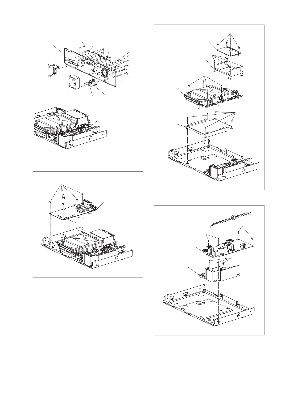
(S-17)
[8] Rear Panel
CN5501
[11] RS232C
CBA
[9] Motor DC Fan
(S-8)
(S-14)
CN1001
(S-13)
(S-8)
(S-13)
(S-8)
[10] Inlet CBA
CN1006
(S-12)
(S-11)
(S-15)
(S-8)
(S-9)
(S-10)
Fig. D4
[13] Video CBA
[14] AV PCB Bracket
[15] *BD Main CBA
& BD Mechanism
Assembly
[16] Loader
Bracket
(S-18)
(S-19)
CN7101
CN6001
CN7601
(S-20)
(S-16)
CN2008
CN2005
[12] Audio CBA
CN2007
Fig. D5
* See Reference Notes 3.
(S-21)
[17] Power Supply
CBA
[18] Power Holder
Fig. D6
(S-22)
(S-23)
15
Fig. D7
Page 18
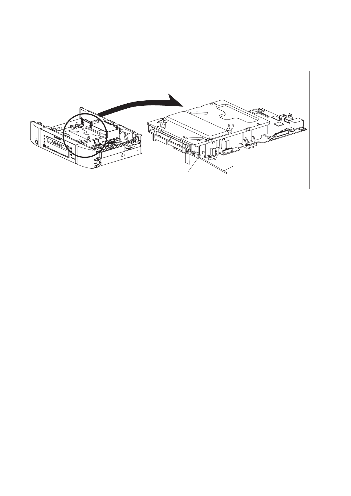
3. How to Eject Manually
1. Remove the Top Cover.
2. Insert a screwdriver, etc. into the straightly so that the Portion A is pushed.
3. Pull the tray out manually and remove a disc.
Portion A
Screwdriver,
hexagon wrench
16
Page 19

8.HOWTOINITIALIZETHEBLU-RAYDISCPLAYER
HOW TO INITIALIZE THE BLU-RAY DISC PLAYER
To put the program back at the factory-default,
initialize the BD player as the following procedure.
1. Turn the power on.
2. Remove the disc on the tray and close the tray.
3. Press [1], [2], [3], [4], and [DISPLAY] buttons on
the remote control unit in that order.
Fig. a appears on the screen.
"
" differ depending on the models.
*******
Version Info
F/W Name
Version
Region
: *******
: *.***
: *-*
EXIT <POWER>EEPROM CLEAR <STOP>
Fig. a
4. Press [ C ] button on the remote control unit.
Fig. b appears on the screen and Fig. c appears
on the VFD.
"
" differ depending on the models.
*******
Version Info
F/W Name
Version
Region
EEPROM CLEAR : OK
: *******
: *.***
: *-*
EXIT <POWER>EEPROM CLEAR <STOP>
Fig. b
Fig. c
5. To exit this mode, press [POWER OFF] button.
17
Page 20
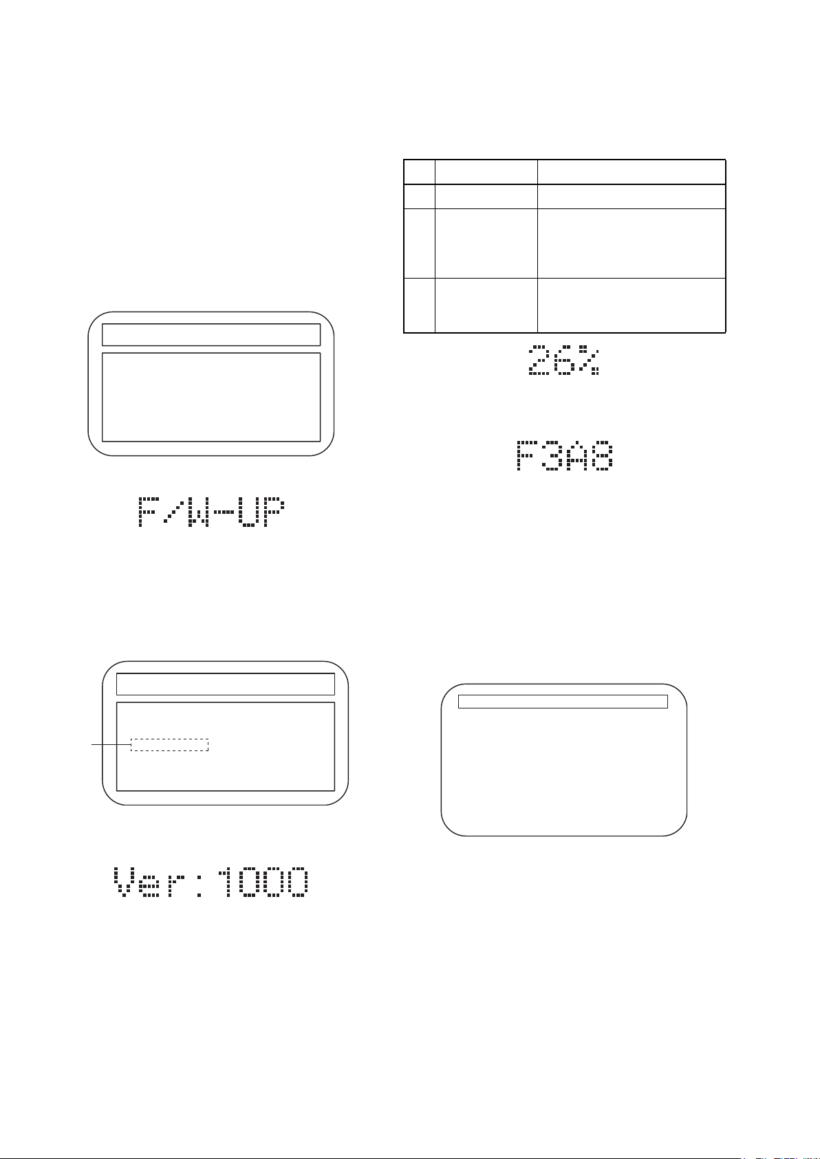
9.FIRMWARERENEWALMODE
FIRMWARE RENEWAL MODE
Note: The file extension of the available firmware is
“b20”.
1. Turn the power on and remove the disc on the tray
and close the tray.
2. To put the BD player into version up mode, press
[9], [8], [7], [6], and [POP UP MENU/MENU]
buttons on the remote control unit in that order.
The tray will open automatically.
Fig. a appears on the screen and Fig. b appears
on the VFD.
"
" differs depending on the models.
*******
F/W VERSION UP MODE F/W Name: ******* Ver. *.***
Please insert a Disc
for F/W Version Up
Fig. a Version Up Mode Screen
Fig. b VFD in Version Up Mode
3. Load the disc for version up.
4. The BD player enters the F/W version up mode
automatically. Fig. c appears on the screen and
Fig. d appears on the VFD. Make sure to insert the
proper F/W for the state of this model.
"
" differs depending on the models.
*******
F/W VERSION UP MODE F/W Name: ******* Ver. *.***
1. ALL
(*1)
Ver. *.*** ************A*.b20
Now Loading...
The appearance shown in (*1) of Fig. c is
described as follows:
No. Appearance State
1 Now Loading... Loading the disc
Sending files into the
2 Reading...
memory.
After reading, automatically
the tray opens.
Writing new version data,
3 See FL Display
the progress will be displayed
as shown in Fig. e.
Fig. e VFD in Vresion Up Mode
5. After programming is finished, the checksum on
the VFD (Fig. f).
VFD upon Finishing the Programming Mode (Example)
Fig. f
Checksum appears on the VFD then the tray will
open automatically. Remove the disc on the tray.
At this time, no button is available.
6. Unplug the AC cord from the AC outlet. Then plug
it again.
7. Turn the power on.
8. Press [1], [2], [3], [4], and [DISPLAY] buttons on
the remote control unit in that order.
Fig. g appears on the screen.
"
" differ depending on the models.
*******
Version Info
F/W Name
Version
Region
: *******
: *.***
: *-*
EXIT : POWER
Fig. c Programming Mode Screen (Example)
Fig. d VFD in Programming Mode (Example)
EXIT <POWER>EEPROM CLEAR <STOP>
Fig. g
18
Page 21

9. Press [ C ] button on the remote control unit.
How to Verify the Firmware Version
Fig. h appears on the screen and Fig. i appears on
the VFD.
"
" differ depending on the models.
*******
Version Info
F/W Name
Version
Region
: *******
: *.***
: *-*
1. Turn the power on.
2. Remove the disc on the tray and close the tray.
3. Press [1], [2], [3], [4], and [DISPLAY] buttons on
the remote control unit in that order.
Fig. j appears on the screen.
"
" differ depending on the models.
*******
Version Info
EEPROM CLEAR : OK
EXIT <POWER>EEPROM CLEAR <STOP>
Fig. h
Fig. i
10. To exit this mode, press [POWER OFF] button.
F/W Name
Version
Region
: *******
: *.***
: *-*
EXIT <POWER>EEPROM CLEAR <STOP>
Fig. j
4. To exit this mode, press [POWER OFF] button.
19
Page 22

10.FIRMWARERENEWALMODE(NetworkUpdate)s
FIRMWARE RENEWAL MODE (Network Update)
1. Press [SETUP] button on the remote control unit in
stop mode.
2. Use [
3. Use [
} / O] button to select “CUSTOM”, then
press [ENTER] button.
} / O] button to select “Other”, then press
[ENTER] button.
4. Use [
X / Y] button to select “Network Update”,
then press [ENTER] button.
Confirmation message will appear.
5. Use [
X / Y] button to select “Yes”, then press
[ENTER] button.
This unit will start checking for the latest firmware
How to Verify the Firmware Version
1. Turn the power on.
2. Remove the disc on the tray and close the tray.
3. Press [1], [2], [3], [4], and [DISPLAY] buttons on
the remote control unit in that order.
Fig. j appears on the screen.
"
" differ depending on the models.
*******
Version Info
F/W Name
Version
Region
: *******
: *.***
: *-*
version.
NOTE:
If any error message concerning the network
environment appears, please confirm the
setting of your unit according to the error
message. If you need to change any of your
network environmental setting in order to
4. To exit this mode, press [POWER OFF] button.
Fig. j
execute the update, please contact to the
internet service provider.
6. Confirmation message will appear.
X / Y] button to select “Yes”, then press
Use [
[ENTER] button.
The unit will start downloading the latest firmware
version.
7. When the download completes, confirmation
message will appear.
Press [ENTER] button.
The unit will start updating the firmware version.
It may take a while to complete the updating.
(Please wait until “100%” appears on the front
panel display.)
8. After updating finishes, this unit will restart and
open the disc tray automatically.
EXIT <POWER>EEPROM CLEAR <STOP>
20
Page 23
11.SERVICEMODE
SERVICE MODE
Service Mode
1 MECHA TEST
2 VFD/LED TEST
3 ERROR RATE
4 LD TEST
CHANNEL
5
TEST
6 SD CARD TEST
DEFAULT
7
SETTING
1st level 2nd level 3rd level Description
1 Tray Aging Aging of tray open/close
2 TOC Read TOC reading
3 Heat Run
1 All On Turning on all VFD
2 All Off Turning off all VFD
1 Off Turning off LD
1 LD Power
2 Operating Time
1 TEST TONE
2 Front Lch
3 Center
4 Front Rch
5 Surround Rch
Surround Back
6
Rch
7 Surround Back Lch
8 Surround Lch
9 Sub woofer
2 BD Turning on BD LD
3 DVD Turning on DVD LD
4 CD Turning on CD LD
Center/Subwoofer/
1
Front LR
Surround LR/
2
Surround Back LR
Tray close -> TT1 playback -> TT10
playback -> Tray open -> Tray close
Displaying Error rate, Jitter
during playback
Displaying LD Operation Time (with
clear function)
Default setting
Note: If some test are performed continuously, any error will occur
21
Page 24

Entering Service Mode
In power on condition, no discs and tray close, it will be entered into service mode by the following operation using
the remote controller. However, it will not be entered when Media Select Item is SD Memory.
Service Mode by using remote controller
Press the following buttons on the remote controller in power on condition, no discs and tray close;
[2]->[5]->[8]->[0]->[CLEAR]
Release from Service Mode
Press the [POWER OFF] button to turn off power.
Screen saver/Auto Power Off in Service Mode
These functions are not performed in Service Mode.
After entering, Fig. k appears on the screen and Fig. l appears on the VFD.
* Firmware Version differs depending on the
models, and this indication is one example.
SERVICE MODE
1: MECHA TEST
2: VFD/LED TEST
3: ERROR RATE MEASURE
4: LD TEST
5: CHANNEL TEST
6: SD CARD TEST
7: DEFAULT SETTING
F/W Name :******* Region
Release Ver. :*.***
ADSP1/2 Ver. :---/--- PLD Ver. :--FPGA Ver. :--- I/P Scaler Ver.:---
:*-*
Fig. k Service Mode (Main Menu)
Fig. I Service Mode
Available button in service mode
Button condition
ENTER Enter the next level
POWER Turn the power off (when the service mode is completed)
1~7 Enter the selected item (next level)
OTHER Not available
Note: Press the number key to select items. Or, press the cursor button (up/down) to select items and press
[ENTER] button.
INDICATION DESCRIPTION REMARK
F/W Name Model Name E5K***D, etc.
Region BD region - DVD region A-1, etc.
Release Ver. Release version D.jpp, etc.
22
Page 25

12.TRAYLOCKMODE
TRAY LOCK MODE
Tray Lock Mode prevents the tray opening or closing to
prevent disc theft in demo mode.
Enter this mode using the following procedure.
1. Confirm that the TV Monitor is connected.
2. With playback stopped, press [SETUP], [TOP
MENU], [3], [AUDIO], [0] and [SETUP] buttons on
the remote control unit in that order. "Trade-On"
appears in the upper right corner on the screen,
and Fig. a appears on the VFD for 2 seconds.
3. To exit this mode, press [SETUP], [TOP MENU],
[3], [AUDIO], [0] and [SETUP] buttons on the
remote control unit in that order. "Trade-Off"
appears in the upper right corner on the screen,
and Fig. b appears on the VFD for 2 seconds.
Fig. a
Fig. b
23
Page 26

13.TROUBLESHOOTING
TROUBLESHOOTING
FLOW CHART NO.1
The power cannot be turned on.
Is the fuse normal?
Is normal state restored when once unplugged
power cord is plugged again after several seconds?
Is the EV+5V line voltage normal?
Check each rectifying circuit of the secondary circuit
and service it if defective.
FLOW CHART NO.2
The fuse blows out.
Check the presence that the primary component
is leaking or shorted and service it if defective.
After servicing, replace the fuse.
FLOW CHART NO.3
When the output voltage fluctuates.
Yes
Yes
Yes
No
No
No
See FLOW CHART No.2 <The fuse blows out.>
Check if there is any leak or short-circuiting on the
primary circuit component, and service it if defective.
(D1007, D1008, D1011, D1012, D1023, D1024,
IC1002, Q1002, T1002, C1022, R1022)
Check the presence that the rectifying diode or
circuit is shorted in each rectifying circuit of
secondary side, and service it if defective.
Does the photo coupler circuit on the secondary
side operate normally?
Yes
Check D1021, IC1002, IC1004 and their periphery,
and service it if defective.
FLOW CHART NO.4
When buzz sound can be heard in the vicinity of power circuit.
Check if there is any short-circuit on the rectifying diode and the circuit in each rectifying circuit of the secondary
side, and service it if defective. (D1025, D1028, D1030, D1031, D1032, D1033, IC1008, IC1009, IC1010, Q1009,
Q1010, Q1011, Q1013, Q2636)
FLOW CHART NO.5
FL is not outputted.
Is 35V voltage supplied to the emitter of Q2602?
Yes
Is the "L" signal outputted to the collector of
Q2603?
Yes
Check Q2601, Q2602, D2603 and their periphery,
and service it if defective.
No
No
No
Check D1029, IC1004 and their periphery,
and service it if defective.
Check D1032, C1033 and periphery circuit,
and service it if defective.
Is the "H" signal inputted to the base of Q2603?
Yes
Replace Q2603.
Check FL-SW line and service
it if defective.
No
24
Page 27

FLOW CHART NO.6
P-ON+5V (1) is not outputted.
Is 5V voltage inputted to the emitter of Q1011?
Yes
Is 4.5V voltage inputted to the base of Q1011?
Yes
No
No
Check D1025, D1030, D1031, C1029, C1034 and
their periphery, and service it if defective.
Check Q1007 and PWSW4 line and service it if
defective.
Replace Q1011.
FLOW CHART NO.7
P-ON+5V (2) is not outputted.
Is 5V voltage inputted to the emitter of Q1009?
Yes
Is 4.5V voltage inputted to the base of Q1009?
Yes
No
No
Check D1025, D1030, D1031, C1029, C1034 and
their periphery, and service it if defective.
Check Q1007 and PWSW4 line and service it if
defective.
Replace Q1009.
FLOW CHART NO.8
P-ON+10.5V is not outputted.
Is 14V voltage inputted to the collector of Q1013?
No
Yes
Is 11V voltage inputted to the base of Q1013? Is 14V voltage inputted to the base of Q1006?
No
Check D1029, D1041, C1026, L1004
and
their periphery, and service it if defective.
Yes Yes No
Replace Q1013.
Check Q1006, D1046,
and their periphery, and
service it if defective.
Check Q1008,
and
PWSW4 line, and
service it if defective.
FLOW CHART NO.9
P-ON+1.2V is not outputted.
Is 5V voltage supplied to Pin(3) of IC1009?
Yes
Is the "L" signal inputted to the base of Q1015?
Yes
Check IC1009, Q1015
and their periphery, and
service it if defective.
FLOW CHART NO.10
P-ON+3.3V is not outputted.
Is 5V voltage supplied to Pin(1) of IC1008?
Yes
ls "L" signal outputted to the collector of Q1005?
Yes
Check IC1008, D1040 and their periphery circuit,
and service it if defective.
No
No
No
No
Check D1025, D1030, D1031, C1029, C1034 and
their periphery, and service it if defective.
Check PWSW2 line and service it if defective.
Check D1025, D1030, D1031, C1029, C1034 and
their periphery, and service it if defective.
Check Q1005 and PWSW1 line and service it if
defective.
25
Page 28

FLOW CHART NO.11
P-ON+1.8V is not outputted.
Is 5V voltage inputted to Pin(3) of IC1010?
Yes
ls "L" signal outputted to the base of Q1016?
Yes
Check IC1010, Q1016
and their periphery, and
service it if defective.
FLOW CHART NO.12
P-ON+14.5V is not outputted.
Is 15V voltage inputted to the emitter of Q1010?
Yes
Is 14V voltage inputted to the base of Q1010?
Yes
Replace Q1010.
FLOW CHART NO.13
The fluorescent display tube does not light up.
Is 3.3V voltage supplied to Pin(24) of FL3001?
No
No
No
No
No
Check D1025, D1030, D1031, C1029, C1034
and their periphery, and service it if defective.
Check PWSW2 line and their periphery, and service it
if defective.
Check D1028, C1026, L1003 and their periphery, and
service it if defective.
Check Q1008 and PWSW4 line and service it if
defective.
Check the EV+3.3V line and service it if defective.
Yes
Is 9V voltage supplied to Pin(1,2) of FL3001?
Yes
Is 5V voltage supplied to Pin(29,30) of FL3001?
Yes
Replace FL3001.
FLOW CHART NO.14
The key operation is not functioning.
Are the contact point and the installation state of
the key switches (SW3002, SW3004-SW3007,
SW3105, SW3107, SW3109) normal?
Yes
When pressing each switches (SW3002,
SW3004-SW3007, SW3105, SW3107, SW3109),
do the voltage of Pin(1, 62) of IC2000 increase?
Yes
Replace IC2000.
No
No
No
No
Is 10V voltage supplied to the emitter of Q2604?
Yes No
Is 9V voltage inputted
to the base of Q2604?
Yes No
Replace Q2604.
Check Q2603 and FL-SW
Check D1033, C1028, R1032,
R1033 and their periphery,
and service it if defective.
line
and service it if defective.
Check the F2
line and service it if defective.
Re-install the switches (SW3002, SW3004-SW3007,
SW3105, SW3107, SW3109) correctly or replace
the poor switch.
Check the switches (SW3002, SW3004-SW3007,
SW3105, SW3107, SW3109) and their periphery,
and service it if detective.
26
Page 29

FLOW CHART NO.15
No operation is possible from the remote control unit.(Operation is possible from the unit.)
Is 5V voltage supplied to Pin(2) of RS3001
No
Check EV+5V line and service it if defective.
(remote control receiver) ?
Yes
Is the "L" pulse sent out Pin(1) of RS3001 (remote
control receiver) when the remote control unit is activated?
Yes
Is the "L" pulse inputted to the Pin(27) of IC2000?
Yes
Replace IC2000.
No
No
Replace the RS3001 (remote control receiver) or
remote control unit.
Check the line between the
receiver)
and the
Pin(27) of IC2000,
defective.
FLOW CHART NO.16
The disc tray cannot be opened and closed. (It can be done using the remote control unit.)
Is the normal control voltage inputted to Pin(62) of
IC2000?
Refer to "FLOW CHART NO.14" <The key
No
Replace the "OPEN/CLOSE" switch (SW3101).
operation is not functioning.>
Yes
Replace the BD Main CBA & BD Mechanism
Assembly.
RS3001 (remote control
and service it if
FLOW CHART NO.17
The disc tray cannot be opened and closed.
[No Disc] indicated.
Both functions of picture and sound do not operate normally.
Yes
Replace the BD Main CBA & BD Mechanism
Assembly.
27
Page 30

FLOW CHART NO.18
Picture does not appear normally.
Set the disc on the disc tray, and playback.
Are the video signals outputted to each pin of
CN4000?
CN4000 3PIN VIDEO
CN4000 5PIN VIDEO-Y(I/P)
CN4000 7PIN VIDEO-Pb/Cb
CN4000 9PIN VIDEO-Pr/Cr
Yes
Are the video signals shown above inputted into
each pin of IC4000?
IC4000 3PIN VIDEO
IC4000 8PIN VIDEO-Y(I/P)
IC4000 10PIN VIDEO-Pb/Cb
IC4000 12PIN VIDEO-Pr/Cr
Yes
Are the video signals outputted to each pin of
IC4000?
IC4000 20PIN VIDEO-Y(I/P)
IC4000 17PIN VIDEO-Pb/Cb
IC4000 15PIN VIDEO-Pr/Cr
IC4000 25PIN VIDEO
Yes
Are the video signals outputted to the specific
output terminal?
Are the component video signals outputted to the
VIDEO OUT terminal (JK4002, JK4003, JK4005)?
Are the composite video signals outputted to
the VIDEO OUT terminal (JK4004)?
No
No
No
No
No
Replace the BD
Main CBA & BD Mechanism
Assembly.
Check the line between each pin of CN4000 and
each pin of IC4000, and service it if defective.
CN4000 3PIN → IC4000 3PIN VIDEO
CN4000 5PIN → IC4000 8PIN VIDEO-Y(I/P)
CN4000 7PIN → IC4000 10PIN VIDEO-Pb/Cb
CN4000 9PIN → IC4000 12PIN VIDEO-Pr/Cr
Is 5V voltage supplied to the Pin(7,21) of IC4000?
Yes
Replace IC4000.
Check VIDEO+5V line and
No
service it if defective.
Check the periphery of the VIDEO OUT terminal
(JK4002, JK4003, JK4005) from Pin(15,17,20) of
IC4000 and service it if defective.
Check
the periphery of the VIDEO OUT terminal
(JK4004)
from Pin(25) of IC4000
and service it if
defective.
28
Page 31

FLOW CHART NO.19
Audio is not outputted normally. (JK2200, JK2201)
Set the disc on the disc tray, and playback.
Are the analog audio signals outputted to each pin
of CN2007?
CN2007 22PIN AUDIO(L)
CN2007 24PIN AUDIO(R)
Yes
Are the analog audio signals inputted to each pin
of IC2200?
IC2200 6PIN AUDIO(L)
IC2200 2PIN AUDIO(R)
Yes
Is the "H" level mute signal outputted to CN2007?
CN2007 19PIN AUDIO(R)-MUTE
CN2007 20PIN AUDIO(L)-MUTE
Yes
Is the signal at Pin(24) of IC2000 "H" ?
Yes
Are the analog audio signals outputted to each pin
of IC2200?
IC2200 7PIN AUDIO(L)
IC2200 1PIN AUDIO(R)
Yes
Are the audio signals outputted to the audio
terminal (JK2200, JK2201)?
No
No
No
No
No
No
Replace the BD
Main CBA & BD Mechanism
Assembly.
Check each line between each pin of CN2007
and each pin of IC2200, and service it if detective.
CN2007 22PIN → IC2200 6PIN AUDIO(L)
CN2007 24PIN → IC2200 2PIN AUDIO(R)
Replace the BD
Main CBA & BD Mechanism
Assembly.
AUDIO-MUTE line, and
Check
service it if
detective.
Replace IC2200.
Check the periphery between Pin(1,7) of IC2200
and the audio terminal (JK2200, JK2201), and
service it if detective.
29
Page 32

FLOW CHART NO.20
Audio is not outputted. (JK2202, JK2203)
Set the disc (with 7.1ch Audio) on the disc tray, and playback.
Are the analog audio signals outputted to each pin
of CN2007?
CN2007 15PIN FRONT-AUDIO(L)
CN2007 17PIN FRONT-AUDIO(R)
CN2007 5PIN SURROUND(L)
CN2007 7PIN SURROUND(R)
CN2007 3PIN SURROUND BACK(L)
CN2007 1PIN SURROUND BACK(R)
CN2007 12PIN CENTER
CN2007 10PIN SUB WOOFER
Yes
Are the analog audio signals inputted to each pin
of IC2601, IC2602, IC2603 and IC2604?
IC2601 2, 6PIN FRONT-AUDIO(L/R)
IC2603 2, 6PIN SURROUND(L/R)
IC2604 2, 6PIN SURROUND BACK(L/R)
IC2602 2, 6PIN CENTER/SUB WOOFER
Yes
Are the analog audio signals outputted to each pin
of IC2601, IC2602, IC2603 and IC2604?
IC2601 1,7PIN FRONT-AUDIO(L/R)
IC2603 1,7PIN SURROUND(L/R)
IC2604 1,7PIN SURROUND BACK(L/R)
IC2602 1,7PIN CENTER/SUB WOOFER
Yes
Do the mute signals of CN2007 become to "H"
level?
FRONT-AUDIO(L) → CN2007 14PIN
FRONT-AUDIO(R) → CN2007 18PIN
SURROUND(L/R) → CN2007 8PIN
SURROUND BACK(L/R) → CN2007 4PIN
CENTER → CN2007 13PIN
SUB WOOFER → CN2007 9PIN
No
No
No
No
Replace the BD Main CBA & BD Mechanism
Assembly.
Check each line between each pin of CN2007
and each pin of IC2601, IC2602,IC2603 and IC2604
and service it if defective.
CN2007 15,17PIN → IC2601 2,6PIN FRONT-AUDIO(L/R)
CN2007 5,7PIN → IC2603 2,6PIN SURROUND(L/R)
CN2007 1,3PIN → IC2604 2,6PIN SURROUND BACK(L/R)
CN2007 10,12PIN → IC2602 2,6PIN CENTER/SUB WOOFER
Replace
ICs (IC2601, IC2602
, IC2603 or IC2604).
Replace the BD Main CBA & BD Mechanism
Assembly.
Yes
Is the analog audio signal of each line outputted to
each terminal of JK2202 and JK2203 (as shown
below) ?
IC2601 7PIN → JK2202 FRONT-AUDIO(L)
IC2601 1PIN → JK2202 FRONT-AUDIO(R)
IC2603 7PIN → JK2202 SURROUND(L)
IC2603 1PIN → JK2202 SURROUND(R)
IC2604 7PIN → JK2203 SURROUND BACK(L)
IC2604 1PIN → JK2203 SURROUND BACK(R)
IC2602 7PIN → JK2202 SUB WOOFER
IC2602 1PIN → JK2202 CENTER
No
Check each line and service it if defective.
30
Page 33

BD Mechanism Replacement Guidelines s
The guidelines describe how to determine whether a BD Mechanism Assembly is defective or not.
Confirm that the malfunction is eliminated after replacing the defective BD Mechanism Assembly with a new one.
*The BD Mechanism Assembly shall be acceptable when the following test disc can be played successfully;
BD-ROM BLX-201S3(SONY) chp12
*Select [4: LD Test] and select [2: Operating Time] in Service Mode.
If the Operating Time shows 3,000 hours or more, the BD Mechanism Assembly shall be determined that it has
reached the end of its life.
Replacement of BD Main CBA & BD Mechanism Assembly
1. Remove the Top Cover, Tray Panel, Front Assembly, Front Bracket, Video CBA and AV PCB Holder.
2. Disconnect Connectors and replace the BD Main CBA & BD Mechanism Assembly.
Refer to CABINET DISASSEMBLY INSTRUCTIONS.
BD Main CBA
& BD Mechanism Assembly
31
Page 34

BLOCK DIAGRAMS
14.BLOCKDIAGRAMS
System Control Block Diagram
RS232C-
CONNECTOR
3 RXD
2 TXD
CN5550
REMOTE
JK5550
-OUT
REMOTE
-IN
EV+3.3V
VFD
19 20 21 22
FL3001
FRONT A CBA
SENSOR
REMOTE
RS3001
D3005
STANDBY
DRIVE
Q3004
POWER
SW3002
CN3001
1
2
KEY-2
KEY-1
CN3101
1
2
KEY
KEY
SWITCH
SWITCH
FRONT B CBA
RS232C CBA
IC5500
RS232C
INTERFACE
CN5551
13
14
RS232C
I/F
11
12
1
IC5550
(PHOTO COUPLER)
4
BUFFER
Q5551, Q5552
-LED
2
12 12REMOTE
CN2002 CN3002
3
BUFFER
Q2002
274934
REMOTE
RS232C-RXD
15 SUB-TXD
21 MUTE1
22 MUTE2
46
SUB-RXD
SYS-RESET
3
16
Q2620, Q2621
Q2618
28 CEC-IN
30 CEC-OUT
SWITCHING
BUFFER
BUFFER
Q2619
(SUB MICRO CONTROLLER)
IC2000
CN2005
RS232C-TXD
45
3 3FL-SDA
33
FL-SDA
5 5FL-STB
4 4FL-SCL
FL-SCL
FL-STB
STANDBY
6 6FL-RESET
15 15KEY-2
18 18
1
60
50
KEY-2
FL-RESET
STANDBY-LED
16 16KEY-1
EV+3.3V
8MHz
X'TAL
X2000
RESET
IC2001
8
9
62
KEY-1
14
RESET
AUDIO-MUTE
24
AUDIO-MUTE
TO AUDIO
BLOCK
DIAGRAM
OSC1
OSC2
32 FL-SW
PWSW1
FL-SW
PWSW237PWSW4
PWSW1
4
44
PWSW2
PWSW4
TO POWER
SUPPLY
BLOCK
FAN-CONT1
25
63 FAN-LOCK
FAN-CONT1
FAN-LOCK
DIAGRAM
AUDIO CBA
REMOTE
RS232C-RXD
RS232C-TXD
1 1
5 5
4 4
CN4002
VIDEO CBA
BD MAIN CBA
REMOTE
6 6
CN4001
RS232C-RXD
RS232C-TXD
1 1
2 2
15 15MUTE1
14 14MUTE2
MUTE1
MUTE2
TO VIDEO
BLOCK
DIAGRAM
CN4000
CN7101
10 10SUB-TXD
11 11SUB-RXD
14 14SUB-TXD
13 13SUB-RXD
JK7501
9 9SYS-RESET
17 17CEC
15 15SYS-RESET
17 17CEC
13
CEC
MAIN MICRO
IC6001
CONTROLLER
IC6903 (EEPROM)
U34
RXD1
SCL0
V31
6
SCL
V32
TXD1
SDA0
W30
5
SDA
IC6401
(ETHERNET INTERFACE)
MII-RXD1
MII-RXD0
MII-RXCLK
J1J3J4
2823222120
JK6401
ETHERNET
JACK
MII-RXD3
MII-RXD2
J2
K2
ETHERNET
121110
123
TX(-)
TX(+)
T34
AE32
XRST
XTRST
MII-TXD0
MII-TXCLK
MII-TXD1
H5
H4
G4
33
INTERFACE
9
6
RX(-)
RX(+)
Q6702
MII-TXD3
MII-TXD2
F4
G5
39
383635
IC6701
Q6701
RESET
2 1
P-ON+1.8V
32
Page 35

Digital Signal Process 1 Block Diagram
VIDEO SIGNAL AUDIO SIGNAL
TO DIGITAL SIGNAL
PROCESS 2 BLOCK
DIAGRAM
(IC6001)
BD+
CSS
AACS
STREAM
FE
DIGITAL
CONTROL
SIGNAL
PROCESS
COPY
PROTECT
CPRM
IC6001 (MAIN MICRO CONTROLLER/DIGITAL SIGNAL PROCESS)
B28
A28
20 SE02
18 SE01
MPX
IC201 (FRONT-END PROCESSOR)
97-100
CN101
ASENV
H34
59
WOB
MATRIX
102-105
A-D 21-24
G34
61 WBL
/LPP
868588
107-110
E-H 26-29
RF(+) 17
B34
C33
666554
RF
EQUALIZER
RF
GENERATOR
87
RF(-) 18
BDRF(-) 15
BDRF(+) 14
53
SCLK1
SDATA2 40
SDATA2
SDATA1
SCLK2
SCLK1
J34
J33
SDATA1
83 78 79
SCLK2 38
M31
M32
IC604 (OP AMP)
IC603 (MOTOR DRIVE)
CN101
TRACKING-CONTROL
E23
1 2
22
TRACKING
ACTUATOR
DRIVE
212019
TD 3
TR 4
FD1 1
FOCUS1-CONTROL
A24
7 6
FOCUS 1
ACTUATOR
DRIVE
18
FR1 2
FD2 6
FOCUS 2
17
FR2 5
EXPA(+) 9
FOCUS2-CONTROL
D23
8 9
12
ACTUATOR
DRIVE
16
EXPA(-) 7
EXPB(-) 8
EXPB(+) 10
EXPA-CONTROL
B22
132310
COLLIMATE
IC602 (MOTOR DRIVE)
236
EXPB-CONTROL
D22
LENS
MOTOR DRIVE
5
SLED1-CONTROL
C24
4
SLED
IC603 (MOTOR DRIVE)
32
33
CN601
SLD2(-) 3
SLD2(+) 4
SLED2-CONTROL
D24
30
MOTOR DRIVE
2
1
SLD1(-) 1
SLD1(+) 2
LOADING
14
CN602
LOAD(+) 5
LOAD-CONTROL
C22
13
MOTOR DRIVE
15
LOAD(-) 6
TRAY-OUT 2
TRAY-OUT
D21
TRAY-IN 1
TRAY-IN
INLIMIT
B3
E21
IC601 (MOTOR DRIVE)
242119131415161718
CN603
W 1
INLIMIT 4
SPINDLE-CONTROL
E24
10
V 2
U 3
SPINDLE
MOTOR
DRIVE
HU(-) 6
HU(+) 5
SPINDLE-FG
B25
4
HV(-) 8
HV(+) 7
HW(+) 9
BD MAIN CBA
12
HB(-) 11
HW(-) 10
BD MECHANISM
OEIC
(CD/DVD)
OEIC
(BD)
LASER
DIODE
DRIVE
33
SLED
MOTOR
LOADING
MOTOR
TRAY-OUT
INNER
SW
TRAY-IN
SPINDLE
MOTOR
Page 36

Digital Signal Process 2 Block Diagram
TO
VIDEO
BLOCK
DIAGRAM
VIDEO
VIDEO SIGNAL AUDIO SIGNAL
BP1-4-Y(0-1)
BP1-4-CR(0-1)
BP1-Y(0-1)
BP1-CO(0-1)
ABT-CB(0-11)
94-102,
IC7201 (SCALER)
1-7,13-16,
BP1-CO(0-11)
ABT-Y(0-11)
111-114,
117-124
108-110
SIGNAL
PROCESS
/SCALER
17-28
176
BP1-Y(0-11)
DQ (0-15)
IC7202 (SDRAM)
MEMORY
CONTROLLER
A (0-11)
SDRAM
BP1-P-CLK
BP1-VSYNC
BP1-HSYNC
12
173
174
ABT-P-CLK
ABT-VSYNC
ABT-HSYNC
90
89
107
ABT-P-CLK
ABT-VSYNC
ABT-HSYNC
27MHz
X6701
1
IC6703 (CLOCK GENE.)
789
+3.3V
IC7206
OSC
16
CLOCK
RESET
170
RESETN
SCL
SDA
163
164
2
3
SCL
SDA
GENE.
10
SCL3
SDA3
REC656-CLK
ANA-SW-CONT
TO
VIDEO
BLOCK
DIAGRAM
MC
MD
HDMI-BCK
HDMI-MCK
HDMI-DATA0
HDMI-DATA1
HDMI-LRCK
HDMI-DATA2
HDMI-DATA3
HDMI-SPDIF
DAC-SCK
DAC-BCK
SPDIF
DAC-LRCK
TO
AUDIO
BLOCK
DIAGRAM
MS2
MS3
MS4
MS5
DATA
MS1
DATA3
DATA0
DATA1
DATA2
IC6001 (MAIN MICRO CONTROLLER/DIGITAL SIGNAL PROCESS)
C15
VIDEO
DAC
A5,E7
B8,E9
CN7601
5 5SDDAT0
DIGITAL
SD I/F
AF32,AG34,
SD DATA(0-3)
3 3SDDAT1
VIDEO
OUT
SDCLK
AH34
AH33,AJ34
7 7SDCLK
15 15SDDAT2
13 13SDDAT3
A4,A8,A9,B4,B9,C5,C9,
C11,D8,D10,E10,E11
A3,A6,A7,B7,C4,C6,C7,
C8,D6,D9,E8,E12
MEDIA
PROCESSOR
TO
DIGITAL
I/P CONVERTER
SIGNAL
PROCESS 1
BLOCK
A2
CLK
/SCALING
DIAGRAM
(IC6001)
B6
B5
VSYNC
HSYNC
AL5
33M CLOCK
Java (BD-J)
MPEG-2
E20
A19
AL34
33M CLOCK
74M CLOCK
27M CLOCK
DiVX
VC-1
H.264
DECODER
ED (0-7)
R33
U31
D20
SCL3
SDA3
768K CLOCK
HD (TS)
SD (PS)
D7
B18
E13
REC656-CLK
ANA-SW-CONT
B10
B11
A10
A11
D11
C12
C0DQ (0-31)
C14
C10
MEMORY
I/F
C0A (0-12)
B14
A12
B13
A13
B12
E14
D14
D13
C13
AC31
C1DQ (0-31)
C1A (0-12)
AC34
AD34
AC32
AC33
D12
DIGITAL
AUDIO
OUT
POWER
SD CBA
SUPPLY CBA
CN5003 CN5004
9 9SDDAT2
19 19SDDAT0
21 21SDDAT1
11 11SDDAT3
17 17SDCLK
CN5001
CN5000
SD
CARD
SLOT
BD MAIN CBA
DDR2 SDRAM
IC6902
(NAND FLASH MEMORY)
NAND FLASH
MEMORY (64M x 8bit)
(DDR2 SDRAM)
IC6501,IC6502
(1Gbit )
IC6601,IC6602
(DDR2 SDRAM)
DDR2 SDRAM
(512Mbit)
34
Page 37

Video Block Diagram
VIDEO OUT
(COMPOSITE)
JK4004
JK4005
VIDEO-Y
OUT
VIDEO-Pb/Cb
OUT
JK4002
VIDEO-Pr/Cr
JK4003
OUT
TO SYSTEM
CONTROL
BLOCK
DIAGRAM
MUTE1
MUTE2
DDC DATA
DDC CLOCK
HOT PLUG
DETECT
191516
JK7501
HDMI-CONNECTOR
T.M.D.S DATA2-
T.M.D.S DATA2+
T.M.D.S DATA1-
T.M.D.S DATA1+
31649
T.M.D.S DATA0-
T.M.D.S DATA0+
T.M.D.S CLOCK+
T.M.D.S CLOCK-
7
10
12
VIDEO SIGNAL AUDIO SIGNAL
VIDEO CBA
C4018
WF3
75Ω
DRIVER
2dB
AMP
LPF 25
4dB
AMP
IC4000 (VIDEO DRIVER)
3
786
6.75MHz
75Ω
2dB
LPF
4dB
8 20
DRIVER
AMP
AMP
17
75Ω
DRIVER
2dB
AMP
LPF
13.5/37MHz
13.5/37MHz
4dB
AMP
10
CN4000CN7101
5 5VIDEO-Y(I/P)
3 3VIDEO
Q7102
15
75Ω
DRIVER
2dB
AMP
LPF
13.5/37MHz
4dB
AMP
12
WF1 WF2
7 7VIDEO-Pb/Cb
9 9VIDEO-Pr/Cr
2
13
MUTE1
MUTE2
118
DDC
AUTHENT
/CATION
KEY
EXCHANGE
REGISTER
IIC
I/F
113
116
CLK
121
IC7501 (HDMI INTERFACE)
I/F
VS
83
23251921151713
120
119
VIDEO
HS
84
50,51,53-57,59,
87,88,90,91
TMDS
SERIALIZER
TMDS
ENCODER
HDCP
CIPHER/
ENCRYPTOR
AV
CONTROLLER
I/F
70-73,75-78,
92,94,102,103
11
AUDIO
I/F
46454442413936
35
PLL
IC7205 (BUFFER)
1
2
3
63
IC7203
(VIDEO DAC)
IC7207
(SW)
VIDEO
30 CLKIN-A CLKIN-B
13
136
ANA-SW-CONT
REC656-CLK
ABT-P-CLK
BD MAIN CBA
555861
BP1-CO(0-1)
TO DIGITAL
SIGNAL
PROCESS 2
BLOCK
BUFFER
Q7103
BUFFER
434244
62
BP1-Y(0-1)
BP1-4-CR(0-1)
DIAGRAM
Q7101
BUFFER
VIDEO
535459
DAC
60
14-18,
ABT-CB(2-11)
BP1-4-Y(0-1)
25-29
ABT-Y(2-11)
2-9,
12,13
SCL
21
SDA
20
P-VSYNC
S-VSYNC
P-HSYNC
23
22
49
S-HSYNC
50
SCL3
SDA3
ABT-HSYNC
ABT-VSYNC
ABT-CB(0-11)
ABT-Y(0-11)
TO DIGITAL
SIGNAL
PROCESS 2
BLOCK
DIAGRAM
HDMI-DATA0
HDMI-DATA1
HDMI-DATA2
HDMI-DATA3
HDMI-MCK
HDMI-BCK
HDMI-LRCK
HDMI-SPDIF
35
Page 38

Audio Block Diagram
SURROUND(L)
-OUT
SURROUND(R)
-OUT
SUB
WOOFER
AUDIO SIGNAL
JK2202
(REAR)
AUDIO CBA
MUTE-ON
Q2631
DRIVE
Q2630
MUTE-ON
Q2632
-OUT
MUTE-ON
Q2627
DRIVE
Q2629
CENTER
-OUT
MUTE-ON
Q2628
DRIVE
Q2626
FRONT-
AUDIO(L)-
Q2624
Q2622
OUT
FRONT-
MUTE-ON
DRIVE
AUDIO(R)-
OUT
MUTE-ON
Q2625
DRIVE
Q2623
JK2203
(REAR)
SURROUND
BACK(L)-
Q2634
Q2633
OUT
SURROUND
MUTE-ON
DRIVE
BACK(R)-
MUTE-ON
Q2635
OUT
JK2200
(REAR)
AUDIO(L)-
OUT
JK2201
MUTE-ON
Q2203
DRIVE
Q2200
AUDIO(R)-
(REAR)
Q2202
Q2201
OUT
MUTE-ON
DRIVE
TO SYSTEM CONTROL
BLOCK DIAGRAM
AUDIO-MUTE
DIGITAL
JK4000
(REAR)
BUFFER
Q4006
AUDIO OUT
(COAXIAL)
IC2603
(OP AMP)
7
6
5 5SURROUND(L)
CN7001 CN2007
SURROUND-MUTE
7 7SURROUND(R)
8 8
10 10SUB WOOFER
1
2
SUB WOOFER-MUTE
9 9
12 12CENTER
7
IC2602
(OP AMP)
6
F-AUDIO(L)-MUTE
F-AUDIO(R)-MUTE
CENTER-MUTE
13 13
15 15FRONT-AUDIO(L)
17 17FRONT-AUDIO(R)
14 14
18 18
SURROUND BACK(L)
3 3
1
2
SURROUND BACK(R)
SURROUND BACK-MUTE
1 1
4 4
IC2601
(OP AMP)
7
7
1
IC2604
6
2
(OP AMP)
1
7
1
6
2
IC2200
(OP AMP)
6
2
WF4
22 22AUDIO(L)
24 24AUDIO(R)
19 19AUDIO(L)-MUTE
20 20AUDIO(R)-MUTE
CN7001 CN2007
CN7101 CN4000
VIDEO CBA
WF5
11 11SPDIF
15
(L-CH)
IC7003
(AUDIO D/A CONVERTER)
3458276
MCMDDAC-SCK
14
(R-CH)
AUDIO
DAC
DAC-BCK
DAC-LRCK
MS3
16
MUTE
DATA1
15
(L-CH)
IC7004
(AUDIO D/A CONVERTER)
3458276
14
(R-CH)
MUTE
AUDIO
DAC
1
16
MUTE
IC7002
(AUDIO D/A CONVERTER)
MS4
DATA2
1
14
15
MUTE
(L-CH)
(R-CH)
AUDIO
DAC
3458276
MS2
TO DIGITAL
SIGNAL
PROCESS 2
16
MUTE
DATA0
BLOCK DIAGRAM
15
(L-CH)
(R-CH)
IC7005
(AUDIO D/A CONVERTER)
3458276
1
14
15
MUTE
(L-CH)
(R-CH)
AUDIO
DAC
3458276
MS1
16
MUTE
DATA
BD MAIN CBA
SPDIF
AUDIO
DAC
MS5
16
MUTE
DATA3
IC7001
(AUDIO D/A CONVERTER)
14
36
Page 39

Power Supply Block Diagram
TO BD MAIN
CBA
(CN6001)
P-ON+1.2V
P-ON+1.8V
2 P-ON+5V(1)
5,6 P-ON+3.3V
9-11
FAN
Q1019
2FAN-LOCK
CN1006
FAN-VCC 1
23 P-ON+5V(2)
17-20
CONTROL
3,4 P-ON+10.5V
CN1003
NOTE:
The voltage for parts in hot circuit is measured using
hot GND as a common terminal.
Q1017
FAN
CONTROL
P-ON+14.5V
Q1010
SW+14.5V
Q1013
SW+10.5V
Q1006
Q1008
LIMIT
CURRENT
Q1012, Q1014
EV+3.3V
AUDIO+3.3V
AUDIO CBA
REG.
+3.3V
Q2636, D2625
CN2008
CN1004
PWSW1
PWSW1
EV+5V
1 1
10 10
TO SYSTEM
PWSW2
PWSW4
PWSW2
PWSW4
11 11
13 13
CONTROL
BLOCK
DIAGRAM
FAN-LOCK
FAN-CONT1
FAN-CONT1
FAN-LOCK
15 15
16 16
FL-SW
Q2604
F1-IN
4 4
F1
Q2601
F2-IN
5 5
+FL
6 6
F2
FL
Q2603
Q2602
FAN
"Ce symbole reprèsente un fusible à fusion rapide."
"This symbol means fast operating fuse."
CAUTION !
For continued protection against fire hazard,
replace only with the same type fuse.
ATTENTION : Pour une protection continue les risqes
d'Incele n'utiliser que des fusible de même type.
Risk of fire-replace fuse as marked.
F
A V
POWER SUPPLY CBA
F
HOT CIRCUIT. BE CAREFUL.
11
T1002
2
BRIDGE
D1007, D1008,
D1011, D1012
LINE
L1001
F1001
2A 250V
A V
RECTIFIER
FILTER
REG.
+1.2V
IC1009
12
)
SWITCHING CONTROL
IC1002
(
Q1015
15
4
2
13
Q1002
5
SWITCHING
CONTROL
1
3
IC1008
VDD
6
+3.3V
REG.
IC1010
10
REG.
+1.8V
Q1001
Q1005
Q1016
9
Q1011
SW+5V
Q1009
16
7
SW+5V
Q1007
REG.
14
6
IC1004
ERROR
VOLTAGE DET
1
4
2
3
HOT
SHUNT
D1029
ERROR
VOLTAGE DET
COLD
CN1002
AC120V
AC120V
1 1
2 2
AC CORD
CAUTION !
Fixed voltage (or Auto voltage selectable) power supply circuit is used in this unit.
If Main Fuse (F1001) is blown , check to see that all components in the power supply
circuit are not defective before you connect the AC plug to the AC power supply.
Otherwise it may cause some components in the power supply circuit to fail.
CN1001
AC INLET
INLET CBA
37
Page 40

SCHEMATIC DIAGRAMS / CBA AND TEST POINTS
15.SCHEMATICDIAGRAMS/CBAANDTESTPOINTS
Standard Notes
WARNING
Many electrical and mechanical parts in this chassis
have special characteristics. These characteristics
often pass unnoticed and the protection afforded by
them cannot necessarily be obtained by using
replacement components rated for higher voltage,
wattage, etc. Replacement parts that have these
special safety characteristics are identified in this
manual and its supplements; electrical components
having such features are identified by the mark “!” in
the schematic diagram and the parts list. Before
replacing any of these components, read the parts list
in this manual carefully. The use of substitute
replacement parts that do not have the same safety
characteristics as specified in the parts list may create
shock, fire, or other hazards.
Notes:
1. Do not use the part number shown on these
drawings for ordering. The correct part number is
shown in the parts list, and may be slightly
different or amended since these drawings were
prepared.
2. All resistance values are indicated in ohms
(K = 10
3. Resistor wattages are 1/4W or 1/6W unless
otherwise specified.
4. All capacitance values are indicated in µF
(P = 10
5. All voltages are DC voltages unless otherwise
specified.V
3
, M = 106).
-6
µF).
38
Page 41

LIST OF CAUTION, NOTES, AND SYMBOLS USED IN THE SCHEMATIC DIAGRAMS ON
THE FOLLOWING PAGES:
1. CAUTION:
FOR CONTINUED PROTECTION AGAINST FIRE HAZARD, REPLACE ONLY WITH THE
F
A V
SAME TYPE FUSE.
ATTENTION: POUR UNE PROTECTION CONTINUE LES RISQES D'INCELE N'UTILISER
QUE DES FUSIBLE DE MÊME TYPE.
RISK OF FIRE-REPLACE FUSE AS MARKED.
This symbol means fast operating fuse.
Ce symbole represente un fusible a fusion rapide.
2. CAUTION:
Fixed Voltage (or Auto voltage selectable) power supply circuit is used in this unit.
If Main Fuse (F1001) is blown, first check to see that all components in the power supply circuit are not
defective before you connect the AC plug to the AC power supply. Otherwise it may cause some components
in the power supply circuit to fail.
3. Note:
1. Do not use the part number shown on the drawings for ordering. The correct part number is shown in the
parts list, and may be slightly different or amended since the drawings were prepared.
2. To maintain original function and reliability of repaired units, use only original replacement parts which are
listed with their part numbers in the parts list section of the service manual.
4. Voltage indications for PLAY and STOP mode on the schematics are as shown below:
2
1
(Unit: Volt)
The same voltage for
both PLAY & STOP modes
5.0
3
5.0
(2.5)
Indicates that the voltage
is not consistent here.
PLAY mode
STOP mode
5. How to read converged lines
1-D3
Distinction Area
Line Number
(1 to 3 digits)
Examples:
1. "1-D3" means that line number "1" goes to the line number
"1" of the area "D3".
2. "1-B1" means that line number "1" goes to the line number
"1" of the area "B1".
3
AREA D3
2
1
A B C D
AREA B1
1-D3
1-B1
6. Test Point Information
: Indicates a test point with a jumper wire across a hole in the PCB.
: Used to indicate a test point with a component lead on foil side.
: Used to indicate a test point with no test pin.
: Used to indicate a test point with a test pin.
39
Page 42

Personal notes:
40
Page 43

Audio 1/3 Schematic Diagram
41 42
Page 44

Audio 2/3 Schematic Diagram
43 44
Page 45

Audio 3/3 Schematic Diagram
45 46
Page 46

Video Schematic Diagram
47 48
Page 47

Power Supply & Inlet Schematic Diagram
CAUTION !
Fixed voltage (or Auto voltage selectable) power supply circuit is used in this unit.
If Main Fuse (F1001) is blown , check to see that all components in the power supply
circuit are not defective before you connect the AC plug to the AC power supply.
Otherwise it may cause some components in the power supply circuit to fail.
F
A V
CAUTION !
For continued protection against fire hazard,
replace only with the same type fuse.
ATTENTION : Pour une protection continue les risqes
d'Incele n'utiliser que des fusible de même type.
Risk of fire-replace fuse as marked.
"This symbol means fast operating fuse."
"Ce symbole reprèsente un fusible à fusion rapide."
NOTE:
The voltage for parts in hot circuit is measured using
hot GND as a common terminal.
49 50
Page 48

Front A & Front B Schematic Diagram
51 52
Page 49

RS232C Schematic Diagram
54 53
Page 50

SD Schematic Diagram
55 56
Page 51

BD Main 1/13 Schematic Diagram
1 NOTE:
The order of pins shown in this diagram is different from that of actual IC6001.
IC6001 is divided into nine and shown as IC6001 (1/9) ~ IC6001 (9/9) in this BD Main Schematic Diagram Section.
57 58
Page 52

BD Main 2/13 Schematic Diagram
1 NOTE:
The order of pins shown in this diagram is different from that of actual IC6001.
IC6001 is divided into nine and shown as IC6001 (1/9) ~ IC6001 (9/9) in this BD Main Schematic Diagram Section.
59 60
Page 53

BD Main 3/13 Schematic Diagram
1 NOTE:
The order of pins shown in this diagram is different from that of actual IC6001.
IC6001 is divided into nine and shown as IC6001 (1/9) ~ IC6001 (9/9) in this BD Main Schematic Diagram Section.
61 62
Page 54

BD Main 4/13 Schematic Diagram
1 NOTE:
The order of pins shown in this diagram is different from that of actual IC6001.
IC6001 is divided into nine and shown as IC6001 (1/9) ~ IC6001 (9/9) in this BD Main Schematic Diagram Section.
63 64
Page 55

BD Main 5/13 Schematic Diagram
1 NOTE:
The order of pins shown in this diagram is different from that of actual IC6001.
IC6001 is divided into nine and shown as IC6001 (1/9) ~ IC6001 (9/9) in this BD Main Schematic Diagram Section.
65 66
Page 56

BD Main 6/13 Schematic Diagram
1 NOTE:
The order of pins shown in this diagram is different from that of actual IC6001.
IC6001 is divided into nine and shown as IC6001 (1/9) ~ IC6001 (9/9) in this BD Main Schematic Diagram Section.
67 68
Page 57

BD Main 7/13 Schematic Diagram
1 NOTE:
The order of pins shown in this diagram is different from that of actual IC6001.
IC6001 is divided into nine and shown as IC6001 (1/9) ~ IC6001 (9/9) in this BD Main Schematic Diagram Section.
69 70
Page 58

BD Main 8/13 Schematic Diagram
71 72
Page 59

BD Main 9/13 Schematic Diagram
1 NOTE:
The order of pins shown in this diagram is different from that of actual IC6001.
IC6001 is divided into nine and shown as IC6001 (1/9) ~ IC6001 (9/9) in this BD Main Schematic Diagram Section.
73 74
Page 60

BD Main 10/13 Schematic Diagram
75 76
Page 61

BD Main 11/13 Schematic Diagram
1 NOTE:
The order of pins shown in this diagram is different from that of actual IC6001.
IC6001 is divided into nine and shown as IC6001 (1/9) ~ IC6001 (9/9) in this BD Main Schematic Diagram Section.
77 78
Page 62

BD Main 12/13 Schematic Diagram
79 80
Page 63

BD Main 13/13 Schematic Diagram
81 82
Page 64

Audio CBA Top View
83 84
Page 65

Audio CBA Bottom View
WF4
WF4
PIN 22 OF
CN2007
85 86
Page 66

Video CBA Top View
Video CBA Bottom View
WF5
WF8
PIN 11 OF
CN4000
WF1 WF2
WF6 WF4
PIN 9 OF
CN4000
PIN 7 OF
CN4000
WF3
C4018
PLUS LEAD
87 88
Page 67

Power Supply CBA Top View
CAUTION !
Fixed voltage (or Auto voltage selectable) power supply circuit is used in this unit.
If Main Fuse (F1001) is blown , check to see that all components in the power supply
circuit are not defective before you connect the AC plug to the AC power supply.
Otherwise it may cause some components in the power supply circuit to fail.
F
A V
CAUTION !
For continued protection against fire hazard,
replace only with the same type fuse.
ATTENTION : Pour une protection continue les risqes
d'Incele n'utiliser que des fusible de même type.
Risk of fire-replace fuse as marked.
"This symbol means fast operating fuse."
"Ce symbole reprèsente un fusible à fusion rapide."
Because a hot chassis ground is present in the power
supply circut, an isolation transformer must be used.
Also, in order to have the ability to increase the input
slowly, when troubleshooting this type power supply
circuit, a variable isolation transformer is required.
NOTE:
The voltage for parts in hot circuit is measured using
hot GND as a common terminal.
89 90
Page 68

Power Supply CBA Bottom View
CAUTION !
Fixed voltage (or Auto voltage selectable) power supply circuit is used in this unit.
If Main Fuse (F1001) is blown , check to see that all components in the power supply
circuit are not defective before you connect the AC plug to the AC power supply.
Otherwise it may cause some components in the power supply circuit to fail.
F
A V
CAUTION !
For continued protection against fire hazard,
replace only with the same type fuse.
ATTENTION : Pour une protection continue les risqes
d'Incele n'utiliser que des fusible de même type.
Risk of fire-replace fuse as marked.
"This symbol means fast operating fuse."
"Ce symbole reprèsente un fusible à fusion rapide."
Because a hot chassis ground is present in the power
supply circut, an isolation transformer must be used.
Also, in order to have the ability to increase the input
slowly, when troubleshooting this type power supply
circuit, a variable isolation transformer is required.
NOTE:
The voltage for parts in hot circuit is measured using
hot GND as a common terminal.
91 92
Page 69

Front A CBA Top View
Front B CBA Top View
Front A CBA Bottom View
Front B CBA Bottom View
BE5KA0F01011
93 94
BE5KA0F01011
Page 70

BE5KA0F01021C
RS232C CBA Top View
RS232C CBA Bottom View
SD CBA Top View
INLET CBA Top View
BE5KA0F01021E
SD CBA Bottom View
INLET CBA Bottom View
BE5KA0F01021B
95 96
Page 71

WAVEFORMS
16. WAVEFORMS
Pin 9 of CN4000
WF1
WF4
Pin 22 of CN2007
VIDEO-Cr 0.2V 10
Pin 7 of CN4000
WF2
VIDEO-Cb 0.2V 10
C4018 PLUS LEAD
WF3
µ
s
µ
s
AUDIO(L) 1V 0.5ms
WF5
Pin 11 of CN4000
SPDIF 1V 0.1
µ
s
20µs0.5VVIDEO-CVBS
NOTE:
Input Signal (DVD)
VIDEO: 75% COLOR BAR
AUDIO: 1KHz, 0dB
97
Page 72

17. WIRING DIAGRAM
WIRING DIAGRAM
RS232C-CONNECTOR
RS232C CBA
FRONT A CBA
CN3001CN3101
1
2
3
KEY-2
GND
KEY-1
123
FRONT B
CBA
FAN
INLET CBA
AC
CORD
SD CBA
SD CARD SLOT
REMOTE
1
EV+5V
2
RS232C-PW-CONT
3
RS232C-TXD
4
CN5501
RS232C-RXD
5
GND
6
F1
1
FL
2
FL-SDA
3
FL-SCL
4
FL-STB
5
FL-RESET
6
GND
7
GND
8
F2
9
GND
10
CN3002
EV+3.3V
11
REMOTE
12
GND
13
EV+5V
14
KEY-2
15
KEY-1
16
NU
17
STANDBY-LED
18
AC120V
1
AC120V
2
CN1001
WP
23
CD
22
SDDAT1
21
GND
20
SDDAT0
19
GND
18
SDCLK
17
D+3.3V
16
D+3.3V
15
GND
14
CMD
13
GND
12
SDDAT3
11
CN5001
GND
10
SDDAT2
9
GND
8
GND
7
GND
6
GND
5
GND
4
GND
3
GND
2
GND
1
FAN-VCC
FAN-LOCK
DIGITAL
AUDIO OUT
(COAXIAL)
1
VIDEO
-Pr/Cr
CN4002
CN4001CN2005
1
RS232C-RXD
1
CN2002
1
EV+5V
1
CN1004 CN2008
CN1006
CN1002
CN5003
OUT
VIDEO
-Pb/Cb
OUT
VIDEO-Y
OUT
VIDEO
-OUT
5
4
3
2
GND
EV+5V
RS232C-TXD
RS232C-PW-CONT
4
5
2
3
AUDIO(R)
-OUT
AUDIO(L)
-OUT
FRONT-
AUDIO(R)
-OUT
FRONT-
AUDIO(L)
-OUT
SUB
WOOFER
-OUT
5
4
3
2
F1-IN
F2-IN
NU
P-ON+14.5V
4
5
3
2
VIDEO CBA
7
6
9
8
10
REMOTE
GND
SYS-RESET
RDY
SUB-TXD
6
7
9
8
10
CENTER
-OUT
SURROUND
(R)-OUT
SURROUND
(L)-OUT
SURROUND
BACK
(R)-OUT
SURROUND
BACK
(L)-OUT
7
6
9
8
10
+FL
GND
NU
GND
PWSW1
6
7
9
8
10
POWER SUPPLY CBA
11
12
13
GND
SUB-RXD
NU
12
11
13
AUDIO CBA
11
12
13
FAN-CONT2(NU)
PWSW2
PWSW4
12
11
13
14
15
MUTE1
MUTE2
15
14
14
15
FAN-CONT1
SAFETY
15
14
10
CN4000
11
12
13
14
15
16
17
16
17
VIDEO+5V
CEC
16
17
10
11
12
13
14
CN2007
15
16
17
18
19
20
21
22
23
24
25
26
16
FAN-LOCK
16
CN5004
10
11
12
13
14
15
23
22
21
20
19
18
17
16
15
14
13
12
CN1003
11
10
2
3
4
5
6
1
2
3
4
5
6
7
8
9
10
11
12
13
14
15
16
17
18
1
2
1
2
23
22
21
20
19
18
17
16
15
14
13
12
11
10
9
8
7
6
5
4
3
2
1
NU
1
GND
2
VIDEO
3
GND
4
VIDEO-Y(I/P)
5
GND
6
VIDEO-Pb/Cb
7
GND
8
VIDEO-Pr/Cr
9
GND
SPDIF
GND
SUB-RXD
SUB-TXD
SYS-RESET
RDY
CEC
SURROUND BACK(R)
1
GND
2
SURROUND BACK(L)
3
SURROUND BACK-MUTE
4
SURROUND(L)
5
GND
6
SURROUND(R)
7
SURROUND-MUTE
8
SUB WOOFER-MUTE
9
SUB WOOFER
GND
CENTER
CENTER-MUTE
F-AUDIO(L)-MUTE
FRONT-AUDIO(L)
GND
FRONT-AUDIO(R)
F-AUDIO(R)-MUTE
AUDIO(L)-MUTE
AUDIO(R)-MUTE
GND
AUDIO(L)
GND
AUDIO(R)
AUDIO+5V
AUDIO+5V
WP
1
CD
2
SDDAT1
3
GND
4
SDDAT0
5
GND
6
SDCLK
7
D+3.3V
8
D+3.3V
9
GND
CMD
GND
SDDAT3
GND
SDDAT2
P-ON+5V(2)
GND
GND
P-ON+1.2V
P-ON+1.2V
P-ON+1.2V
P-ON+1.2V
GND
GND
GND
GND
GND
P-ON+1.8V
P-ON+1.8V
9
P-ON+1.8V
8
GND
7
GND
6
P-ON+3.3V
5
P-ON+3.3V
4
P-ON+10.5V
3
P-ON+10.5V
2
P-ON+5V(1)
1
NU
1
2
3
4
5
6
7
8
9
10
CN7101
11
12
13
14
15
16
17
1
2
3
4
5
6
7
8
9
10
11
12
13
14
CN7001
15
16
17
18
19
20
21
22
23
24
25
26
BD MAIN CBA
15
14
13
12
11
10
9
8
7
CN7601
6
5
4
3
2
1
23
22
21
20
19
18
17
16
15
14
13
12
CN6001
11
10
9
8
7
6
5
4
3
2
1
CN101CN601
CN603
CN602
EXPA(-)
EXPB(-)
EXPA(+)
EXPB(+)
PI-CONT
BDRF(+)
BDRF(-)
THERMO
SEN-LDD
SDATA2
TEST-V
SLD1(-)
SLD1(+)
SLD2(-)
SLD2(+)
FD1
FR1
TD
TR
FR2
FD2
SA-INT
GND
GND
RF(+)
RF(-)
GND
+5V
VC-PD
GND
GND
+3.3V
GND
GND
+5V
+8V
SCLK2
XREST
LDEN
NU
NU
W
+5V
HU(+)
HU(-)
HV(+)
HV(-)
HW(+)
HW(-)
HB(-)
TRAY-IN
TRAY-OUT
INLIMIT
LOAD(+)
LOAD(-)
1
2
3
4
5
6
7
8
9
10
11
12
13
14
15
16
17
18
19
20
21
A
22
B
23
C
24
D
25
26
E
27
F
G
28
H
29
30
31
32
33
34
35
36
37
38
39
40
41
42
43
44
45
1
2
3
4
1
V
2
U
3
4
5
6
7
8
9
10
11
GND
HDMI-CONNECTORETHERNET JACK
CD/DVD
-OEIC
LASER DIODE DRIVE
M
M
11
22
33
44
55
RELAY CBA
66
LENS DRIVE
BD-OEIC
BD-LD
CD-LD
PD-LD
DVD-LD
SLED
MOTOR
SPINDLE
MOTOR
BD MAIN CBA & BD MECHANISM ASSEMBLY
PICKUP
-OUT
TRAY
-IN
TRAY
SW
INNER
M
LOADING
MOTOR
98
Page 73

LEAD IDENTIFICATIONS
18. LEAD IDENTIFICATIONS
2SA1980M Y
2SA1980MG-AT
2SC5343MG-AT
KRA104M-AT/P
KRC102M-AT/P
KRC103M-AT/P
KRC106M-AT/P
KTC3199-GR-AT/P
KTA1267(GR, Y)-AT/P
RN1203(TE4 F T)
RN1206
SRA2204M-AT
E C B
SRC1202M-AT
SRC1206M-AT
SRC1203MAT
BD9323EFJ-E2
FA5573N-D1-TE1
8 5
1 4
2SA1015-(GR, Y)(TE2 F T)
2SA1981Y-AT
2SA950-Y(TE2 F T)
2SA966-Y(TE6 F M)
2SC1815-GR(TE2 F T)
2SC2120-Y(TE2 F T)
2SC5344 Y
KTA1271-Y-AT/P
KTC3203-Y-AT/P
STB1277LY-AT
E C B
EL817(B, C)
LTV-817(B, C)-F
PS2561A-1(W)
PST8430NR
S-80930CNMC-G80T2(G, J)
5 4
1
2
1: Anode
4
2: Cathode
3
3: Emitter
4: Collector
1 2 3
KTA1273-Y-AT/P
R A K
KHB4D5N60F-U/PMC
NJM4580E-TE1
8 5
G D S
1 4
MN101C77A GC
48
49
64
1
PQ070XF01SZH
PQ070XFC1SZF
1 2 3 4
MM1757EHBE
33
15
14
16
32
17
28
1
KTC2026-Y/P 2SK3563(Q)
2SK3563(Q M)
E C B
G D S
ADM232AARN
SP232ACN-L/TR
16
1
STC403
B C E
2SC3928A-T112-1Z
2SC5343SFG
2SC5343SG
KTC3875S-GR-RTK/P
9
B E
8
C
Note:
A: Anode
K: Cathode
E: Emitter
C: Collector
B: Base
R: Reference
G: Gate
D: Drain
S: Source
99
Page 74

Personal notes:
100
Page 75

EXPLODED VIEWS
19. EXPLODED VIEW AND PARTS LIST
Cabinet
See Electrical Parts List
for parts with this mark.
Some Ref. Numbers are
not in sequence.
Audio CBA
2L032
W006
RS232C CBA
2L032
B70
Video CBA
2L056
2L028
W009
B71
2L034
2L054
2L082
A3
A26
A14
B72
BD Main CBA &
BD Mechanism
Assembly
A26
A26
FM1001
2L081
2L061
2L070
2L081
2L070
2L079
2L073
2L081
2L082
2L083
2L072
2L089
2L081
2L082
A20-2
A20-1
A8
2L090
Front A CBA
2L064
A1X
2L036
2L018
B2
2L018
2L090
B76
2L018
SD CBA
2L018
Front B CBA
2L051
2L036
2L057
A2
A6
B73
A20-3
2L040
A6
A22
A6
F1001
2L036
W007
2L015
A4
Inlet CBA
2L027
B75
B49
Power Supply CBA
B74
2L026
2L058
B4
101 102
Page 76

Packing
Some Ref. Numbers
are not in sequence.
S1
X1
X11
Lower SideUpper Side
X41 X40 X15 X14 X6
X10
P.W.B.
NAME
BD 1B1 9H2189002140M PWB ASSY
AV 9H2189002150M PWB ASSY AV ASSEMBLY 1VSA21908
POWER 9H2189002160M PWB ASSY POWER ASSEMBLY 1VSA21907
PACKING
POWER X15 00D9H26000887 MAINS CORD
POS. NO. PART NO. (MZ) PART NAME DESCRIPTION
A1X 9H2402002110M PANEL FRONT ASSEMBLY E5KB0UD 1VM123079
A2 nsp CHASSIS CHASSIS E5KA0UD 1VM021192
A4 nsp PANEL REAR PANEL E5KB0UD 1VM227396
A6 9H2407002120M LEG FOOT ASSEMBLY E5KB0UD 1VM431645
A8 9H2418002130M ESCUTCHEON TRAY PANEL ASSEMBLY E5KB0UD 1VM227256
FM1001 9H2685001110S MOTOR MOTOR DC FAN 2D65BL100190 MMEZR12XNR08
W006 9H2606002000S CORD WIRE ASSEMBLY FFC 26/169/1.0 WX1E5KA0-006
BD MAIN CBA & BD MECHANISM
ASSEMBLY
X1! 9H2541002170M USER GUIDE OWNERS MANUAL E5KB0UD 1VMN27573
AC CORD WITH A GND WIRE UL/CSA/ 162/
NO/BLACK
X15 9H2611002050S CORD
X19 9H2307002180M UNIT KIT REMOTE CONTROL UNIT RC004BD NB423UD
CORD W/O A GND WIRE UL/CSA(VW-
1)/152/NO/
N77B0BUN
WAV0162LW001
WAV0152LTE01
A20
S3
X19
S1
NOT STANDARD SPARE PART
A3 9H2403001970D LID TOP COVER E5KA0UD 1VM021193
S1 9H2533002190M CUSHION SIDE PAD E5KB0UD 1VM123119
S2 9H2531002200M PACKING CASE GIFT BOX CARTON E5KB0UD 1VM330460
X14 9H2605002100S CORD AV CORD 1000/BLACK WPZ0102TM018
X14 00D9H26000762 CORD AV CORD RCA(M*2)TO RCA(M*2) WPZ0102LTE01
ELECTRICAL PART
AUDIO JK2200 9H2646000490S TERMINAL RCA JACK MSP-251V-10 GILT LF JXRL010LY143
AUDIO JK2202 9H2646002210M TERMINAL RCA JACK 6PIN MSD-246V-21 GILT LF JXRL060LY169
AUDIO JK2203 9H2646002220M TERMINAL RCA JACK 2PIN MSD-242V-12 GILT LF JXRL020LY168
RS232C JK5550 9H2643001890S TERMINAL
RS232C JK5550 00D2048729008 TERMINAL PHONE JACK HSJ1003-016020 JYSL020HD007
JACK HPEP SML PCB L MSJ-035-50B AG
(PPO)
JYSL020LY009
S2
A20
103 104
 Loading...