

Page 1
Service
BD7003
BD7003 /
N1B/R1B/S1B
Manual
SECTION PAGE
TECHNICAL SPECIFICATIONS ........................................................................................... 1
SERVICE HINTS AND TOOLS ............................................................................................. 4
WARNING AND LASER SAFETY INSTRUCTION ............................................................... 5
LASER BEAM SAFETY PRECAUTIONS ............................................................................. 6
IMPORTANT SAFETY PRECAUTIONS ................................................................................ 7
STANDARD NOTES FOR SERVICING................................................................................. 9
CABINET DISASSEMBLY INSTRUCTIONS ....................................................................... 13
HOW TO INITIALIZE THE BLU-RAY DISC PLAYER .......................................................... 16
TRAY LOCK MODE ............................................................................................................ 17
SERVICE MODE ................................................................................................................. 18
FIRMWARE RENEWAL MODE .......................................................................................... 20
TROUBLESHOOTING ........................................................................................................ 22
WIRING DIAGRAM ............................................................................................................. 28
BLOCK DIAGRAMS ............................................................................................................ 29
LEAD IDENTIFICATIONS ................................................................................................... 35
WAVEFORMS ..................................................................................................................... 36
SCHEMATIC DIAGRAMS AND TEST POINTS .................................................................. 37
PARTS LOCATION .............................................................................................................. 81
EXPLODED VIEWS ............................................................................................................ 91
PARTS LIST ........................................................................................................................ 93
BLU-RAY DISC Player
TABLE OF CONTENTS
Please use this service manual with referring to the user guide ( D.F.U. ) without fail.
BD7003
Part no. 90M12DW855020
First Issue 2008.11
MZ
Page 2
MARANTZ DESIGN AND SERVICE
USA
MARANTZ AMERICA, INC
100 CORPORATE DRIVE
MAHWAH, NEW JERSEY 07430
USA
EUROPE / TRADING
D&M EUROPE B. V.
P. O. BOX 8744, BUILDING SILVERPOINT
BEEMDSTRAAT 11, 5653 MA EINDHOVEN
THE NETHERLANDS
PHONE : +31 - 40 - 2507844
FAX : +31 - 40 - 2507860
KOREA
D&M SALES AND MARKETING KOREA LTD.
CHUNG JIN B/D., #1001,
53-5, WONHYORO 3 GA, YONGSAN-GU,
SEOUL, 140-719, KOREA
PHONE : +82 - 2 - 323 - 2155
FAX : +82 - 2 - 323 - 2154
CANADA
D&M Canada Inc.
5-505 APPLE CREEK BLVD.
MARKHAM, ONTARIO L3R 5B1
CANADA
PHONE : 905 - 415 - 9292
FAX : 905 - 475 - 4159
JAPAN
D&M BUILDING, 2-1 NISSHIN-CHO,
KAWASAKI-KU, KAWASAKI-SHI,
KANAGAWA, 210-8569 JAPAN
D&M Holdings Inc.
CHINA
D&M SALES AND MARKETING SHANGHAI LTD.
ROOM.808 SHANGHAI AIRPORT CITY TERMINAL
NO.1600 NANJING (WEST) ROAD, SHANGHAI,
CHINA. 200040
TEL : 021 - 6248 - 5151
FAX : 021 - 6248 - 4434
Using superior design and selected high grade components,
Only original
MARANTZ
parts can insure that your
MARANTZ
MARANTZ
product will continue to perform to the specifications for which
company has created the ultimate in stereo sound.
it is famous.
Parts for your
MARANTZ
ORDERING PARTS :
equipment are generally available to our National Marantz Subsidiary or Agent.
Parts can be ordered either by mail or by Fax.. In both cases, the correct part number has to be specified.
The following information must be supplied to eliminate delays in processing your order :
1. Complete address
2. Complete part numbers and quantities required
3. Description of parts
4. Model number for which part is required
5. Way of shipment
6. Signature : any order form or Fax. must be signed, otherwise such part order will be considered as null and void.
NOTE ON SAFETY :
Symbol Fire or electrical shock hazard. Only original parts should be used to replaced any part marked with symbol .
Any other component substitution (other than original type), may increase risk of fire or electrical shock hazard.
安全上の注意:
がついている部品は、安全上重要な部品です。必ず指定されている部品番号のものを使用して下さい。
SHOCK, FIRE HAZARD SERVICE TEST :
CAUTION : After servicing this appliance and prior to returning to customer, measure the resistance between either primary AC
cord connector pins ( with unit NOT connected to AC mains and its Power switch ON ), and the face or Front Panel of product
and controls and chassis bottom.
Any resistance measurement less than 1 Megohms should cause unit to be repaired or corrected before AC power is applied,
and verified before it is return to the user/customer.
In case of difficulties, do not hesitate to contact the Technical
Department at above mentioned address.
080702MZ
Page 3

TECHNICAL SPECIFICATIONS
SIGNAL SYSTEM
NTSC/PAL color
APPLICABLE DISCS
(1) BD/DVD-video Discs
1-layer 12 cm single-sided discs, 2-layer 12 cm single sided discs, 2-layer 12 cm double-sided discs
(1 layer per side)
1-layer 8 cm single-sided discs, 2-layer 8 cm single-
sided discs, 2-layer 8 cm double-sided discs
(1 layer per side)
(2) BD-RE / BD-R (Recorded in BDMV format)
1-layer 12 cm single-sided discs, 2-layer 12 cm single sided discs
1-layer 8 cm single-sided discs, 2-layer 8 cm single-
sided discs
(3) DVD-R
1-layer 12 cm single-sided discs, 2-layer 12 cm single sided discs
1-layer 8 cm single-sided discs, 2-layer 8 cm single-
sided discs
(4) DVD-RW
1-layer 12 cm single-sided discs
1-layer 8 cm single-sided discs
(5) Compact discs (audio CD)
12 cm discs, 8 cm discs
(6) CD-RW/-R
12 cm discs, 8 cm discs
APPLICABLE MEMORY CARDS
(1) SD Memory Card
(2) SDHC Memory Card
(3) miniSD Card
(4) microSD Card
VIDEO OUTPUT
Y output level : 1 Vp-p (75 Ω)
Output connectors : Pin jack, 1 set
COMPONENT OUTPUT
Y output level : 1 Vp-p (75 Ω)
PB/CB output level : 0.7 Vp-p (75 Ω)
PR/CR output level : 0.7 Vp-p (75 Ω)
Output connectors : Pin jacks, 1 set
HDMI OUTPUT
Output jack : 19-pin HDMI terminal, 1 set
HDMI ver. 1.3a (Deep Color, Dolby Digital Plus, Dolby TrueHD,
DTS-HD)
ANALOG AUDIO OUTPUT
Output level : 2 Vrms (10 kΩ)
2 channel (L, R) output connector : Pin jacks,
AUDIO OUTPUT PROPERTIES
(1) Frequency response
1 BDs (linear PCM) : 20 Hz to 22 kHz (48 kHz sampling)
: 20 Hz to 44 kHz (96 kHz sampling)
: 20 Hz to 44 kHz (192 kHz sampling)
2 DVDs (linear PCM) : 20 Hz to 22 kHz (48 kHz sampling)
: 20 Hz to 44 kHz (96 kHz sampling)
3 CDs : 20 Hz to 20 kHz
(2) S/N ratio : 115 dB
(3) Total harmonic distortion : 1 kHz 0.004 %
(4) Dynamic range : 100 dB (BD/DVD) / 98dB (CD)
DIGITAL AUDIO OUTPUT
Coaxial digital output : Pin jack, 1 set
POWER SUPPLY
AC 110 V - 240 V, 50 Hz
POWER CONSUMPTION
30 W (Standby : 0.8 W)
MAXIMUM EXTERNAL DIMENSIONS
W : 440 mm (17-3/8")
H : 81.5 mm (3-1/4")
D : 368.2 mm (14-1/2")
(including protruding parts)
MASS
4.2 kg (9.26 lb)
REMOTE CONTROL : RC003BD
Infrared pulse type
Supply : DC 3 V, 2 R6P/AA batteries
External dimensions:
W : 52 mm (2-1/16")
H : 227 mm (8-15/16")
D : 30 mm (1-3/16")
Mass : 171 g (0.4 lb) (batteries included)
1
Page 4
2
ENGLISHSVENSKA ITALIANO
ESPAÑOL
DEUTSCHNEDERLANDS FRANÇAIS
• Handle the discs so that fingerprints and dust do not adhere to
the surfaces of the discs.
• Always store the disc in its protective case when it is not used.
• Note that discs with special shapes cannot be played on this
product. Do not attempt to play back such discs, as they may
damage the unit.
• When a disc becomes dirty, clean it with a cleaning cloth. Wipe
the disc from the centre to out. Do not wipe in a circular motion.
• Do not use solvents such as benzine, thinner, commercially
available cleaners, detergent, abrasive cleaning agents or
antistatic spray intended for analogue records.
This unit is compatible to play back the following discs.
To play back a BD or DVD, make sure that it meets the
requirements for region codes and colour systems as described on
page 5. You can play back discs that have the following logos on
the disc. Other disc types are not guaranteed to play back.
About Discs
Disc Handling
Cleaning Discs
Playable Discs and Files
Playable discs Logos
Blu-ray Disc
- BD-video
- BD-RE (ver.3.0)
(Recorded in BDMV format)
- BD-R (ver.2.0)
(Recorded in BDMV format)
(Unclosed discs may not be played back.)
DVD-video
DVD-RW (Finalised discs only)
DVD-R
DVD-R DL
(Finalised discs only)
CD-DA (audio CD)
CD-RW
Playable discs Logos
CD-R
Kodak Picture CD
DTS - CD (5.1 Music Disc)
Playable files Logos Media
MP3
DVD-RW/-R
CD-RW/-R
SD Memory Card
(including SDHC)
miniSD Card
microSD Card
Windows Media™
Audio
JPEG
DivX
®
DVD-RW/-R
CD-RW/-R
Note
• Discs containing the DivX® files with the DivX®GMC (Global
Motion Compensation) playback feature, which is DivX
®
supplemental function, cannot be played back on this unit.
• This unit cannot play back the disc contents protected by
Windows Media™ Digital Rights Management (DRM).
• “WMA” (Windows Media™ Audio) is an audio codec
developed by Microsoft® in the United States of America.
Readable cards Playable files / data
SD Memory Card (8MB - 2GB)
MP3, Windows Media™ Audio,
JPEG, Picture-in-picture
commentary, subtitles or other
extras for BD-ROM Profile 1.1
SDHC Memory Card (4GB)
miniSD Card (8MB - 2GB)
microSD Card (8MB - 2GB)
—
—
—
Introduction Introduction
ESPAÑOL
• Handle the discs so that fingerprints and dust do not adhere to
the surfaces of the discs.
• Always store the disc in its protective case when it is not used.
• Note that discs with special shapes cannot be played on this
product. Do not attempt to play back such discs, as they may
damage the unit.
• When a disc becomes dirty, clean it with a cleaning cloth. Wipe
the disc from the centre to out. Do not wipe in a circular motion.
• Do not use solvents such as benzine, thinner, commercially
available cleaners, detergent, abrasive cleaning agents or
antistatic spray intended for analogue records.
This unit is compatible to play back the following discs.
To play back a BD or DVD, make sure that it meets the
requirements for region codes and colour systems as described on
page 5. You can play back discs that have the following logos on
the disc. Other disc types are not guaranteed to play back.
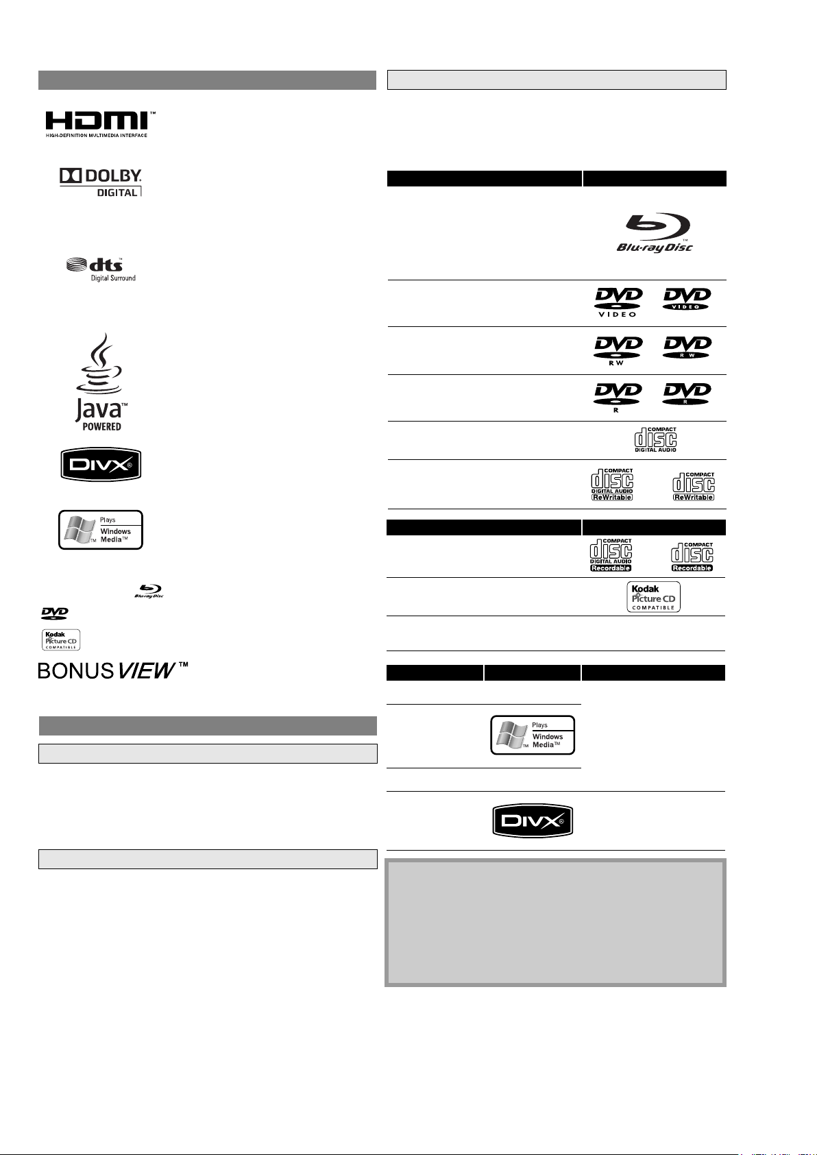
Trademark Information
HDMI, the HDMI logo and HighDefinition Multimedia Interface are
trademarks or registered trademarks of
HDMI Licensing LLC.
Manufactured under license from Dolby
Laboratories. Dolby and the double-D
symbol are trademarks of Dolby
Laboratories.
Manufactured under license under U.S.
Patent #’s: 5,451,942; 5,956,674;
5,974,380; 5,978,762; 6,487,535 & other
U.S. and worldwide patents issued &
pending. DTS and DTS Digital Surround
are registered trademarks and the DTS
logos and Symbol are trademarks of
DTS, Inc. © 1996-2007 DTS, Inc. All Rights
Reserved.
Java and all other trademarks and logos
are trademarks or registered trademarks
of Sun Microsystems, Inc. in the United
States and/or other countries.
DivX, DivX Certified, and associated
logos are trademarks of DivX, Inc. and
are used under license.
Windows Media and the Windows logo
are trademarks or registered trademarks
of Microsoft Corporation in the United
States and/or other countries.
“Blu-ray Disc” and are trademarks.
is a trademark of DVD Format/Logo Licensing Corporation.
is a trademark of Eastman Kodak Company.
“BONUSVIEW” is a trademark of Blu-ray Disc Association.
About Discs
Disc Handling
Cleaning Discs
Playable Discs and Files
Playable discs Logos
Blu-ray Disc
- BD-video
- BD-RE (ver.3.0)
(Recorded in BDMV format)
- BD-R (ver.2.0)
(Recorded in BDMV format)
(Unclosed discs may not be played back.)
DVD-video
DVD-RW (Finalised discs only)
DVD-R
DVD-R DL
(Finalised discs only)
CD-DA (audio CD)
Playable discs Logos
CD-R
Kodak Picture CD
DTS - CD (5.1 Music Disc)
Playable files Logos Media
MP3
Windows Media™
Audio
JPEG
DivX
®
Note
• Discs containing the DivX
Motion Compensation) playback feature, which is DivX
supplemental function, cannot be played back on this unit.
• This unit cannot play back the disc contents protected by
Windows Media™ Digital Rights Management (DRM).
• “WMA” (Windows Media™ Audio) is an audio codec
developed by Microsoft® in the United States of America.
Readable cards Playable files / data
SD Memory Card (8MB - 2GB)
SDHC Memory Card (4GB)
miniSD Card (8MB - 2GB)
microSD Card (8MB - 2GB)
ENGLISHSVENSKA ITALIANO
ESPAÑOL
DEUTSCHNEDERLANDS FRANÇAIS
• Handle the discs so that fingerprints and dust do not adhere to
the surfaces of the discs.
• Always store the disc in its protective case when it is not used.
• Note that discs with special shapes cannot be played on this
product. Do not attempt to play back such discs, as they may
damage the unit.
• When a disc becomes dirty, clean it with a cleaning cloth. Wipe
the disc from the centre to out. Do not wipe in a circular motion.
• Do not use solvents such as benzine, thinner, commercially
available cleaners, detergent, abrasive cleaning agents or
antistatic spray intended for analogue records.
About Discs
Disc Handling
Cleaning Discs
Playable discs Logos
CD-R
Kodak Picture CD
DTS - CD (5.1 Music Disc)
Playable files Logos Media
MP3
DVD-RW/-R
CD-RW/-R
SD Memory Card
Windows Media™
—
—
ENGLISHSVENSKA ITALIANO
ESPAÑOL
DEUTSCHNEDERLANDS FRANÇAIS
Playable discs Logos
CD-R
Kodak Picture CD
DTS - CD (5.1 Music Disc)
Playable files Logos Media
MP3
DVD-RW/-R
CD-RW/-R
SD Memory Card
(including SDHC)
miniSD Card
microSD Card
Windows Media™
Audio
JPEG
DivX
®
DVD-RW/-R
CD-RW/-R
Note
• Discs containing the DivX® files with the DivX®GMC (Global
Motion Compensation) playback feature, which is DivX
®
supplemental function, cannot be played back on this unit.
• This unit cannot play back the disc contents protected by
Windows Media™ Digital Rights Management (DRM).
• “WMA” (Windows Media™ Audio) is an audio codec
developed by Microsoft® in the United States of America.
—
—
—
Page 5
3
ENGLISHSVENSKA ITALIANO
DEUTSCHNEDERLANDS FRANÇAIS
Playable discs Logos
CD-R
Kodak Picture CD
DTS - CD (5.1 Music Disc)
Playable files Logos Media
MP3
DVD-RW/-R
CD-RW/-R
SD Memory Card
(including SDHC)
miniSD Card
microSD Card
Windows Media™
Audio
JPEG
DivX
®
DVD-RW/-R
CD-RW/-R
Note
• Discs containing the DivX® files with the DivX®GMC (Global
Motion Compensation) playback feature, which is DivX
®
supplemental function, cannot be played back on this unit.
• This unit cannot play back the disc contents protected by
Windows Media™ Digital Rights Management (DRM).
• “WMA” (Windows Media™ Audio) is an audio codec
developed by Microsoft® in the United States of America.
Readable cards Playable files / data
SD Memory Card (8MB - 2GB)
MP3, Windows Media™ Audio,
JPEG, Picture-in-picture
commentary, subtitles or other
extras for BD-ROM Profile 1.1
SDHC Memory Card (4GB)
miniSD Card (8MB - 2GB)
microSD Card (8MB - 2GB)
—
—
—
Introduction Introduction
ESPAÑOL
DEUTSCH NEDERLANDSFRANÇAIS
The following discs will not play back on this unit.
BD and DVD are recorded in different colour systems throughout
the world. The most common colour system, used primarily in the
U.K. and other EU countries, is PAL. This unit uses the PAL system.
However, it is also possible to play back BD and DVD using other
colour systems, such as NTSC.
This unit has been designed to play back BD with
region C and DVD-video with region 5. You cannot
play back BD or DVD-video that are labelled for other
regions. Look for the symbols on the right on your BD
or DVD-video. If these region symbols do not appear
on your BD or DVD-video, you cannot play back the
disc in this unit. The letter or number inside the
globe refers to region of the world. A BD or
DVD-video labelled for a specific region can only play
back on the unit with the same region code.
The contents of BD / DVD are generally divided into titles. Titles
may be further subdivided into chapters.
To specify for which media type each function is, we put the
following symbols at the beginning of each item to operate.
Note for SD Memory Cards
• Do not remove the SD Memory Card or turn off the unit while
the contents of the card is in playback. It may result in
malfunction or loss of the card’s data.
• Please keep the SD Memory Cards in their cases when you are
not using them.
• Do not try to open or modify the card.
• Do not touch the terminal surface with your fingers or any
metals.
• Do not attach additional labels or stickers to cards.
• Do not remove the label of the SD Memory Cards.
• This unit supports SD Memory Card with FAT12/FAT16 file
system, and SDHC Memory Card with FAT32 file system.
• This unit may not read the SD Memory Cards formatted on
computer. If that is the case, please reformat the SD Memory
Cards on this unit and try again.
• This unit does not support mini SDHC and micro SDHC
Memory Card.
• For miniSD Card and microSD Card adapter is necessary.
• Portions of this product are protected under copyright law
and are provided under license by ARIS/SOLANA/4C.
Unplayable Discs
• BD-RE Ver.1.0 (BD-disc with cartridge)
• BD-RE (Ver.2.0) (Recorded in BDAV format)
• BD-R (Ver.1.0) (Recorded in BDAV format)
• BD contains MP3/ Windows Media™ Audio/ JPEG/ DivX
®
files
• BD/DVD hybrid disc (e.g., Total Hi Def hybrid disc)
miniSD Card
Adapter
miniSD Card
microSD Card
Adapter
microSD Card
• Super audio CD (Only the sound on the CD layer can be heard.
The sound on the high-density super audio CD layer cannot be
heard.)
• DVD-audio
• HD DVD
• Disc with recording area less than 55mm in diameter
• Unauthorised disc (Pirated disc)
• Unfinalised disc
Colour Systems
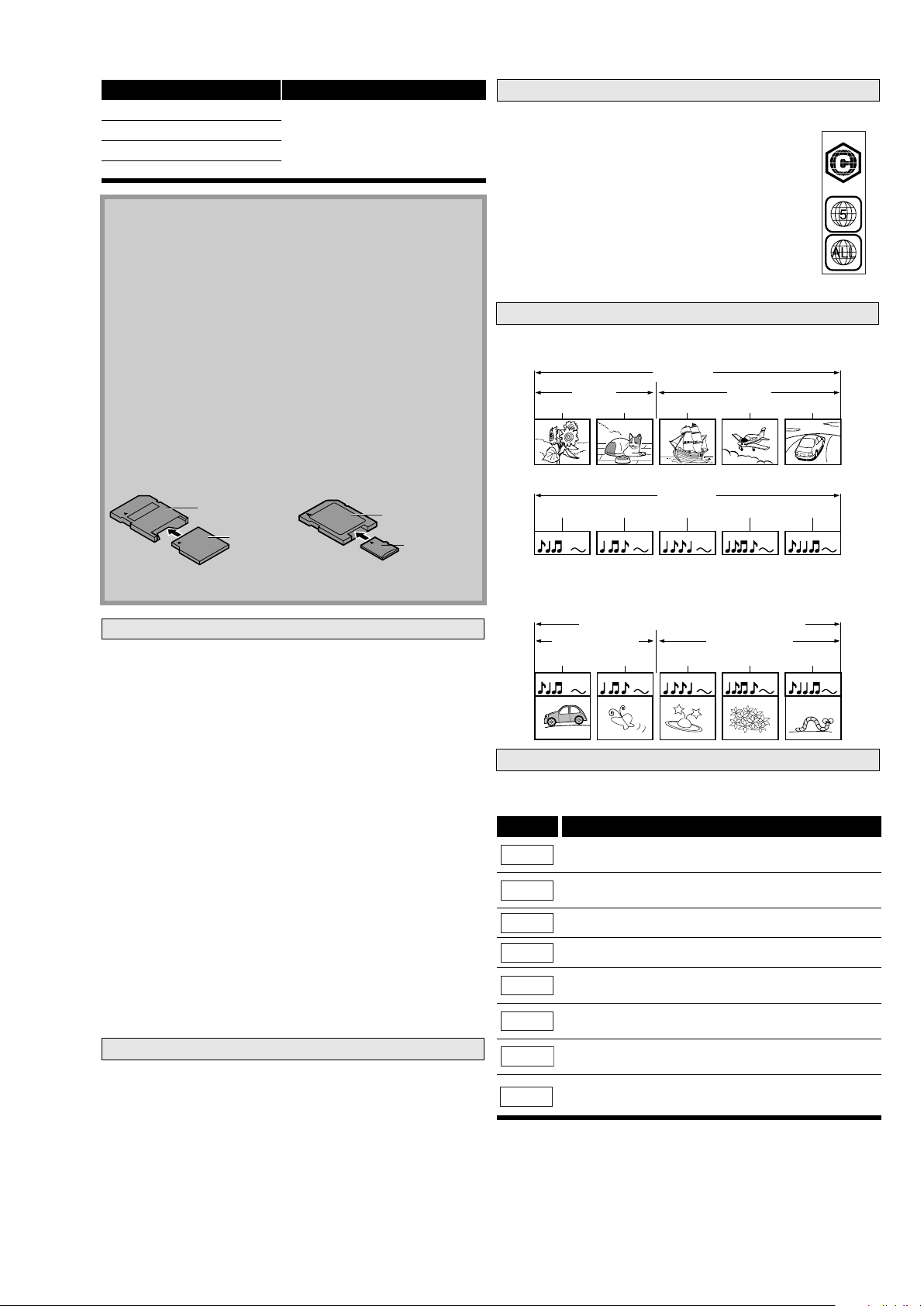
Region Codes
Structure of Disc/SD Memory Card Contents
BD-video
DVD-video
BD/DVD
Symbols Used in this User Guide
Symbol Description
Description refers to BD-video and BD-RE (ver. 3.0)/
BD-R (ver.2.0) recorded in BDMV mode
Description refers to DVD-video and DVD-RW/-R
recorded in video mode
Description refers to DVD-RW/-R recorded in VR mode
Description refers to audio CD and DTS-CD
Description refers to DVD-RW/-R, CD-RW/-R and
SD Memory Card with MP3 files
Description refers to DVD-RW/-R, CD-RW/-R and
SD Memory Card with Windows Media™ Audio files
Description refers to DVD-RW/-R, CD-RW/-R and
SD Memory Card with JPEG files
Description refers to DVD-RW/-R and CD-RW/-R with
DivX
®
files
group(folder)1 group(folder)2
MP3, Windows Media™ Audio, JPEG, DivX
folder (group) 1 folder (group) 2
file (track) 1 file (track) 2 file (track) 3 file (track) 4 file (track) 5
Data discs or SD Memory Cards containing MP3/Windows Media™
Audio/JPEG/DivX
®
is divided into folders, and the folders are
subdivided into files.
BD-V
DVD-V
DVD-VR
CD
MP3
WMA
JPEG
DivX
®
Introduction Introduction
ESPAÑOL
DEUTSCH NEDERLANDSFRANÇAIS
The following discs will not play back on this unit.
BD and DVD are recorded in different colour systems throughout
the world. The most common colour system, used primarily in the
U.K. and other EU countries, is PAL. This unit uses the PAL system.
However, it is also possible to play back BD and DVD using other
colour systems, such as NTSC.
This unit has been designed to play back BD with
region C and DVD-video with region 5. You cannot
play back BD or DVD-video that are labelled for other
regions. Look for the symbols on the right on your BD
or DVD-video. If these region symbols do not appear
on your BD or DVD-video, you cannot play back the
disc in this unit. The letter or number inside the
globe refers to region of the world. A BD or
DVD-video labelled for a specific region can only play
back on the unit with the same region code.
The contents of BD / DVD are generally divided into titles. Titles
may be further subdivided into chapters.
To specify for which media type each function is, we put the
following symbols at the beginning of each item to operate.
If you do not find any of the symbols listed above under the
function heading, the operation is applicable to all media.
Note for SD Memory Cards
• Do not remove the SD Memory Card or turn off the unit while
the contents of the card is in playback. It may result in
malfunction or loss of the card’s data.
• Please keep the SD Memory Cards in their cases when you are
not using them.
• Do not try to open or modify the card.
• Do not touch the terminal surface with your fingers or any
metals.
• Do not attach additional labels or stickers to cards.
• Do not remove the label of the SD Memory Cards.
• This unit supports SD Memory Card with FAT12/FAT16 file
system, and SDHC Memory Card with FAT32 file system.
• This unit may not read the SD Memory Cards formatted on
computer. If that is the case, please reformat the SD Memory
Cards on this unit and try again.
• This unit does not support mini SDHC and micro SDHC
Memory Card.
• For miniSD Card and microSD Card adapter is necessary.
• Portions of this product are protected under copyright law
and are provided under license by ARIS/SOLANA/4C.
Unplayable Discs
• BD-RE Ver.1.0 (BD-disc with cartridge)
• BD-RE (Ver.2.0) (Recorded in BDAV format)
• BD-R (Ver.1.0) (Recorded in BDAV format)
• BD contains MP3/ Windows Media™ Audio/ JPEG/ DivX
®
files
• BD/DVD hybrid disc (e.g., Total Hi Def hybrid disc)
• BD-video that does not include “C” on its region code.
• DVD-video that does not include either “5” nor “ALL” on its
region code.
• DVD-ROM/RAM (For DVD-ROM discs, data files in DivX
®
3.11, 4.x,
5.x and 6 can be played)
• DVD-RW/-R recorded in non-compatible recording format
• CD-ROM (Data files in DivX® 3.11, 4.x, 5.x and 6 can be played)
• CDV (Only the audio part can be played)
• CD-G (Only the audio signals can be output)
• CompactDisc-Interactive (CD-I)
• Video Single Disc (VSD)
• Video CD, Super Video CD
miniSD Card
Adapter
miniSD Card
microSD Card
Adapter
microSD Card
• Super audio CD (Only the sound on the CD layer can be heard.
The sound on the high-density super audio CD layer cannot be
heard.)
• DVD-audio
• HD DVD
• Disc with recording area less than 55mm in diameter
• Unauthorised disc (Pirated disc)
• Unfinalised disc
Colour Systems
Region Codes
Structure of Disc/SD Memory Card Contents
BD-video
DVD-video
audio CD
title 1 title 2
Audio CD
chapter 1 chapter 2 chapter 1 chapter 2 chapter 3
track 1 track 2 track 3 track 4 track 5
Audio CDs are divided into tracks.
BD/DVD
Symbols Used in this User Guide
Symbol Description
Description refers to BD-video and BD-RE (ver. 3.0)/
BD-R (ver.2.0) recorded in BDMV mode
Description refers to DVD-video and DVD-RW/-R
recorded in video mode
Description refers to DVD-RW/-R recorded in VR mode
Description refers to audio CD and DTS-CD
Description refers to DVD-RW/-R, CD-RW/-R and
SD Memory Card with MP3 files
Description refers to DVD-RW/-R, CD-RW/-R and
SD Memory Card with Windows Media™ Audio files
Description refers to DVD-RW/-R, CD-RW/-R and
SD Memory Card with JPEG files
Description refers to DVD-RW/-R and CD-RW/-R with
DivX
®
files
group(folder)1 group(folder)2
MP3, Windows Media™ Audio, JPEG, DivX
folder (group) 1 folder (group) 2
file (track) 1 file (track) 2 file (track) 3 file (track) 4 file (track) 5
Data discs or SD Memory Cards containing MP3/Windows Media™
Audio/JPEG/DivX
®
is divided into folders, and the folders are
subdivided into files.
BD-V
DVD-V
DVD-VR
CD
MP3
WMA
JPEG
DivX
®
About the button names in this explanation
Button name only:
Buttons on the main unit and remote control
< > : Buttons on the main unit
[ ] : Buttons on the remote control
To specify for which media type each function is, we put the
following symbols at the beginning of each item to operate.
Symbols Used in this User Guide
Symbol Description
Description refers to BD-video and BD-RE (ver. 3.0)/
BD-R (ver.2.0) recorded in BDMV mode
Description refers to DVD-video and DVD-RW/-R
recorded in video mode
Description refers to DVD-RW/-R recorded in VR mode
Description refers to audio CD and DTS-CD
Description refers to DVD-RW/-R, CD-RW/-R and
SD Memory Card with MP3 files
Description refers to DVD-RW/-R, CD-RW/-R and
SD Memory Card with Windows Media™ Audio files
Description refers to DVD-RW/-R, CD-RW/-R and
SD Memory Card with JPEG files
Description refers to DVD-RW/-R and CD-RW/-R with
DivX
®
files
MP3, WMA, JPEG, DivX®
group(folder)1 group(folder)2
MP3, Windows Media™ Audio, JPEG, DivX
®
folder (group) 1 folder (group) 2
file (track) 1 file (track) 2 file (track) 3 file (track) 4 file (track) 5
Data discs or SD Memory Cards containing MP3/Windows Media™
Audio/JPEG/DivX
®
is divided into folders, and the folders are
subdivided into files.
BD-V
DVD-V
DVD-VR
CD
MP3
WMA
JPEG
DivX
®
BD and DVD are recorded in different colour systems throughout
the world. The most common colour system, used primarily in the
U.K. and other EU countries, is PAL. This unit uses the PAL system.
However, it is also possible to play back BD and DVD using other
colour systems, such as NTSC.
To specify for which media type each function is, we put the
following symbols at the beginning of each item to operate.
• Super audio CD (Only the sound on the CD layer can be heard.
The sound on the high-density super audio CD layer cannot be
heard.)
• DVD-audio
• HD DVD
• Disc with recording area less than 55mm in diameter
• Unauthorised disc (Pirated disc)
• Unfinalised disc
Colour Systems
Symbols Used in this User Guide
MP3, WMA, JPEG, DivX®
group(folder)1 group(folder)2
MP3, Windows Media™ Audio, JPEG, DivX
®
folder (group) 1 folder (group) 2
file (track) 1 file (track) 2 file (track) 3 file (track) 4 file (track) 5
Data discs or SD Memory Cards containing MP3/Windows Media™
Audio/JPEG/DivX
®
is divided into folders, and the folders are
subdivided into files.
BD and DVD are recorded in different colour systems throughout
the world. The most common colour system, used primarily in the
U.K. and other EU countries, is PAL. This unit uses the PAL system.
However, it is also possible to play back BD and DVD using other
colour systems, such as NTSC.
This unit has been designed to play back BD with
region C and DVD-video with region 5. You cannot
play back BD or DVD-video that are labelled for other
regions. Look for the symbols on the right on your BD
or DVD-video. If these region symbols do not appear
on your BD or DVD-video, you cannot play back the
disc in this unit. The letter or number inside the
globe refers to region of the world. A BD or
DVD-video labelled for a specific region can only play
back on the unit with the same region code.
The contents of BD / DVD are generally divided into titles. Titles
may be further subdivided into chapters.
To specify for which media type each function is, we put the
following symbols at the beginning of each item to operate.
If you do not find any of the symbols listed above under the
function heading, the operation is applicable to all media.
• Super audio CD (Only the sound on the CD layer can be heard.
The sound on the high-density super audio CD layer cannot be
heard.)
• DVD-audio
• HD DVD
• Disc with recording area less than 55mm in diameter
• Unauthorised disc (Pirated disc)
• Unfinalised disc
Colour Systems
Region Codes
Structure of Disc/SD Memory Card Contents
BD-video
DVD-video
audio CD
title 1 title 2
Audio CD
chapter 1 chapter 2 chapter 1 chapter 2 chapter 3
track 1 track 2 track 3 track 4 track 5
Audio CDs are divided into tracks.
BD/DVD
Symbols Used in this User Guide
Symbol Description
Description refers to BD-video and BD-RE (ver. 3.0)/
BD-R (ver.2.0) recorded in BDMV mode
Description refers to DVD-video and DVD-RW/-R
recorded in video mode
Description refers to DVD-RW/-R recorded in VR mode
Description refers to audio CD and DTS-CD
Description refers to DVD-RW/-R, CD-RW/-R and
SD Memory Card with MP3 files
Description refers to DVD-RW/-R, CD-RW/-R and
SD Memory Card with Windows Media™ Audio files
Description refers to DVD-RW/-R, CD-RW/-R and
SD Memory Card with JPEG files
Description refers to DVD-RW/-R and CD-RW/-R with
DivX
®
files
MP3, WMA, JPEG, DivX®
group(folder)1 group(folder)2
MP3, Windows Media™ Audio, JPEG, DivX
®
folder (group) 1 folder (group) 2
file (track) 1 file (track) 2 file (track) 3 file (track) 4 file (track) 5
Data discs or SD Memory Cards containing MP3/Windows Media™
Audio/JPEG/DivX
®
is divided into folders, and the folders are
subdivided into files.
BD-V
DVD-V
DVD-VR
CD
MP3
WMA
JPEG
DivX
®
About the button names in this explanation
Button name only:
Buttons on the main unit and remote control
< > : Buttons on the main unit
[ ] : Buttons on the remote control
BD and DVD are recorded in different colour systems throughout
the world. The most common colour system, used primarily in the
U.K. and other EU countries, is PAL. This unit uses the PAL system.
However, it is also possible to play back BD and DVD using other
colour systems, such as NTSC.
To specify for which media type each function is, we put the
following symbols at the beginning of each item to operate.
• Super audio CD (Only the sound on the CD layer can be heard.
The sound on the high-density super audio CD layer cannot be
heard.)
• DVD-audio
• HD DVD
• Disc with recording area less than 55mm in diameter
• Unauthorised disc (Pirated disc)
• Unfinalised disc
Colour Systems
Region Codes
Symbols Used in this User Guide
Symbol Description
MP3, WMA, JPEG, DivX®
group(folder)1 group(folder)2
MP3, Windows Media™ Audio, JPEG, DivX
®
folder (group) 1 folder (group) 2
file (track) 1 file (track) 2 file (track) 3 file (track) 4 file (track) 5
Data discs or SD Memory Cards containing MP3/Windows Media™
Audio/JPEG/DivX
®
is divided into folders, and the folders are
subdivided into files.
This unit has been designed to play back BD with
To specify for which media type each function is, we put the
following symbols at the beginning of each item to operate.
BD-video
DVD-video
Symbols Used in this User Guide
Symbol Description
Description refers to BD-video and BD-RE (ver. 3.0)/
BD-R (ver.2.0) recorded in BDMV mode
Description refers to DVD-video and DVD-RW/-R
recorded in video mode
Description refers to DVD-RW/-R recorded in VR mode
Description refers to audio CD and DTS-CD
Description refers to DVD-RW/-R, CD-RW/-R and
SD Memory Card with MP3 files
Description refers to DVD-RW/-R, CD-RW/-R and
SD Memory Card with Windows Media™ Audio files
MP3, WMA, JPEG , DivX®
group(folder)1 group(folder)2
MP3, Windows Media™ Audio, JPEG, DivX
®
folder (group) 1 folder (group) 2
file (track) 1 file (track) 2 file (track) 3 file (track) 4 file (track) 5
Data discs or SD Memory Cards containing MP3/Windows Media™
Audio/JPEG/DivX
®
is divided into folders, and the folders are
subdivided into files.
BD-V
DVD-V
DVD-VR
CD
MP3
WMA
region B (N1B), C (R1B), A (S1B) and DVD-video with
region 2 (N1B), 5 (R1B), 3 (S1B). You cannot play back
BD or DVD-video that are labelled for other regions.
Look for the symbols on the right on your BD or DVDvideo. If these region symbols do not appear on your
BD or DVD-video, you cannot play back the disc in this
unit. The letter or number inside the globe refers to
region of the world. A BD or DVD-video labelled for a
specic region can only play back on the unit with the
same region code.
Ex. : R1B
Page 6
4
DVD test disc (NTSC) ALMEDIO TDV-540
SERVICE TOOLS
Audio signals disc 4822 397 30184
Disc without errors (SBC444)+
Disc with DO errors, black spots and fingerprints (SBC444A) 4822 397 30245
Disc (65 min 1kHz) without no pause 4822 397 30155
Max. diameter disc (58.0 mm) 4822 397 60141
Torx screwdrivers
Set (straight) 4822 395 50145
Set (square) 4822 395 50132
13th order filter 4822 395 30204
DVD test disc (PAL) 4822 397 10131
SERVICE HINTS
SERVICE HINTS AND TOOLS
Page 7
5
F
ATTENTION
Tous les IC et beaucoup d’autres semiconducteurs sont sensibles aux décharges
statiques (ESD).
Leur longévité pourrait être considérablement
écourtée par le fait qu’aucune précaution
n’est prise a leur manipulation.
Lors de réparations, s’assurer de bien être
relié au même potentiel que la masse de
l’appareil et enfiler le bracelet serti d’une
résistance de sécurité.
Veiller a ce que les composants ainsi que les
outils que l’on utilise soient également a ce
potentiel.
D
WARNUNG
Alle IC und viele andere Halbleiter sind
empfindlich gegen elektrostatische
Entladungen (ESD).
Unsorgfältige Behandlung bei der Reparatur
kann die Lebensdauer drastisch vermindern.
Sorgen sie dafür, das Sie im Reparaturfall
über ein Pulsarmband mit Widerstand mit
dem Massepotential des Gerätes verbunden
sind.
Halten Sie Bauteile und Hilfsmittel ebenfalls
auf diesem Potential.
WAARSCHUWING
Alle IC’s en vele andere halfgeleiders zijn
gevoelig voor elektrostatische ontladingen
(ESD).
Onzorgvuldig behandelen tijdens reparatie
kan de levensduur drastisch doen
verminderen.
Zorg ervoor dat u tijdens reparatie via een
polsband met weerstand verbonden bent met
hetzelfde potentiaal als de massa van het
apparaat.
Houd componenten en hulpmiddelen ook op
ditzelfde potentiaal.
AVVERTIMENTO
Tutti IC e parecchi semi-conduttori sono
sensibili alle scariche statiche (ESD).
La loro longevita potrebbe essere fortemente
ridatta in caso di non osservazione della piu
grande cauzione alla loro manipolazione.
Durante le riparazioni occorre quindi essere
collegato allo stesso potenziale che quello
della massa dell’apparecchio tramite un
braccialetto a resistenza.
Assicurarsi che i componenti e anche gli
utensili con quali si lavora siano anche a
questo potenziale.
All ICs and many other semi-conductors are
susceptible to electrostatic discharges (ESD).
Careless handling during repair can reduce
life drastically.
When repairing, make sure that you are
connected with the same potential as the
mass of the set via a wrist wrap with
resistance.
Keep components and tools also at this
potential.
WARNING
Safety regulations require that the set be restored to its original condition
and that parts which are identical with those specified be used.
Veiligheidsbepalingen vereisen, dat het apparaat in zijn oorspronkelijke
toestand wordt terug gebracht en dat onderdelen, identiek aan de
gespecifieerde worden toegepast.
Bei jeder Reparatur sind die geltenden Sicherheitsvorschriften zu beachten.
Der Originalzustand des Gerats darf nicht verandert werden.
Fur Reparaturen sind Original-Ersatzteile zu verwenden.
Le norme di sicurezza esigono che l’apparecchio venga rimesso nelle
condizioni originali e che siano utilizzati pezzi di ricambiago idetici a quelli
specificati.
Les normes de sécurité exigent que l’appareil soit remis a l’état d’origine et
que soient utilisées les pièces de rechange identiques à celles spécifiées.
“Pour votre sécurité, ces documents
doivent être utilisés par des
spécialistes agrées, seuls habilités à
réparer votre appareil en panne.”
GB
NL
I
D
I
F
GB
NL
LASER SAFETY
CAUTION VISIBLE AND INVISIBLE LASER RADIATION WHEN OPEN AVOID EXPOSURE TO BEAM
ADVARSEL SYNLIG OG USYNLIG LASERSTRÅLING VED ÅBNING UNDGÅ UDS
Æ
TTELSE FOR STRÅLING
ADVARSEL SYNLIG OG USYNLIG LASERSTRÅLING NÅR DEKSEL Å PNES UNNGÅ EKSPONERING FOR STRÅLEN
VARNING SYNLIG OCH OSYNLIG LASERSTRÅLNING NÄR DENNA DEL ÄR ÖPPNAD BETRAKTA EJ STRÅLEN
VARO! AVATT AESSA OLET ALTTIINA NÄKYVÄLLE JA NÄKYMÄTTÖMÄLLE LASER SÄTEILYLLE. ÄLÄ KATSO SÄTEESEEN
VORSICHT SICHTBARE UND UNSICHTBARE LASERSTRAHLUNG WENN ABDECKUNG GEÖFFNET NICHT DEM STRAHL AUSSETSEN
DANGER VISIBLE AND INVISIBLE LASER RADIATION WHEN OPEN AVOID DIRECT EXPOSURE TO BEAM
ATTENTION RAYONNEMENT LASER VISIBLE ET INVISIBLE EN CAS D'OUVERTURE EXPOSITION DANGEREUSE AU FAISCEAU
USE OF CONTROLS OR ADJUSTMENTS OR PERFORMANCE OF PROCEDURE OTHER THAN THOSE
SPECIFIED HEREIN MAY RESULT IN HAZARDOUS RADIATION EXPOSURE.
AVOID DIRECT EXPOSURE TO BEAM
WARNING
The use of optical instruments with this product will increase eye hazard.
Repair handling should take place as much as possible with a disc loaded inside the player
WARNING LOCATION: INSIDE ON LASER COVERSHIELD
This unit employs a laser. Only a qualified service person should remove the cover or attempt to service this
device, due to possible eye injury.
030804ecm
WARNING AND LASER SAFETY INSTRUCTION
Page 8
6
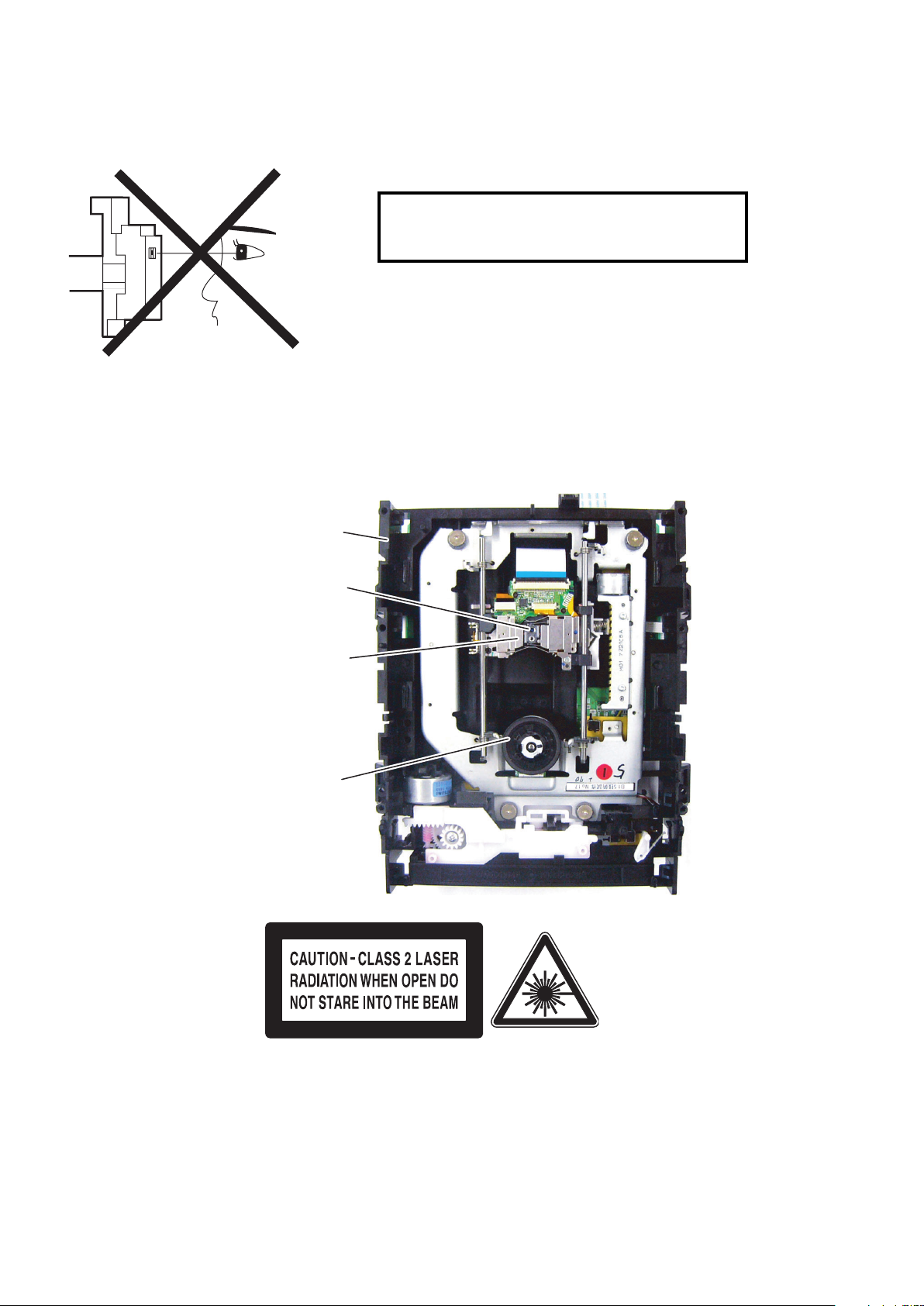
LASER BEAM SAFETY PRECAUTIONS
This BD player uses a pickup that emits a laser beam.
The laser beam is emitted from the location shown in the figure. When checking the laser diode, be sure to keep
your eyes at least 30 cm away from the pickup lens when the diode is turned on. Do not look directly at the laser
beam.
CAUTION: Use of controls and adjustments, or doing procedures other than those specified herein, may result in
hazardous radiation exposure.
Location: Inside Top of BD mechanism.
Do not look directly at the laser beam coming
from the pickup or allow it to strike against your
skin.
Drive Mechanism Assembly
Laser Beam Radiation
Laser Pickup
Turntable
LASER BEAM SAFETY PRECAUTIONS
Page 9

7
IMPORTANT SAFETY PRECAUTIONS
Product Safety Notice
Some electrical and mechanical parts have special
safety-related characteristics which are often not evident from visual inspection, nor can the protection
they give necessarily be obtained by replacing them
with components rated for higher voltage, wattage,
etc. Parts that have special safety characteristics are
identified by a ! on schematics and in parts lists. Use
of a substitute replacement that does not have the
same safety characteristics as the recommended
replacement part might create shock, fire, and/or other
hazards. The Product’s Safety is under review continuously and new instructions are issued whenever
appropriate. Prior to shipment from the factory, our
products are carefully inspected to confirm with the
recognized product safety and electrical codes of the
countries in which they are to be sold. However, in
order to maintain such compliance, it is equally important to implement the following precautions when a set
is being serviced.
Precautions during Servicing
A. Parts identified by the ! symbol are critical for
safety. Replace only with part number specified.
B. In addition to safety, other parts and assemblies
are specified for conformance with regulations
applying to spurious radiation. These must also be
replaced only with specified replacements.
Examples: RF converters, RF cables, noise blocking capacitors, and noise blocking filters, etc.
C. Use specified internal wiring. Note especially:
1)Wires covered with PVC tubing
2)Double insulated wires
3)High voltage leads
D. Use specified insulating materials for hazardous
live parts. Note especially:
1)Insulation tape
2)PVC tubing
3)Spacers
4)Insulators for transistors
E. When replacing AC primary side components
(transformers, power cord, etc.), wrap ends of
wires securely about the terminals before soldering.
F. Observe that the wires do not contact heat produc-
ing parts (heatsinks, oxide metal film resistors, fusible resistors, etc.).
G. Check that replaced wires do not contact sharp
edges or pointed parts.
H. When a power cord has been replaced, check that
5 - 6 kg of force in any direction will not loosen it.
I. Also check areas surrounding repaired locations.
J. Use care that foreign objects (screws, solder drop-
lets, etc.) do not remain inside the set.
K. When connecting or disconnecting the internal
connectors, first, disconnect the AC plug from the
AC outlet.
IMPORTANT SAFETY PRECAUTIONS
Page 10
8
Safety Check after Servicing
Examine the area surrounding the repaired location
for damage or deterioration. Observe that screws,
parts, and wires have been returned to their original
positions. Afterwards, do the following tests and confirm the specified values to verify compliance with
safety standards.
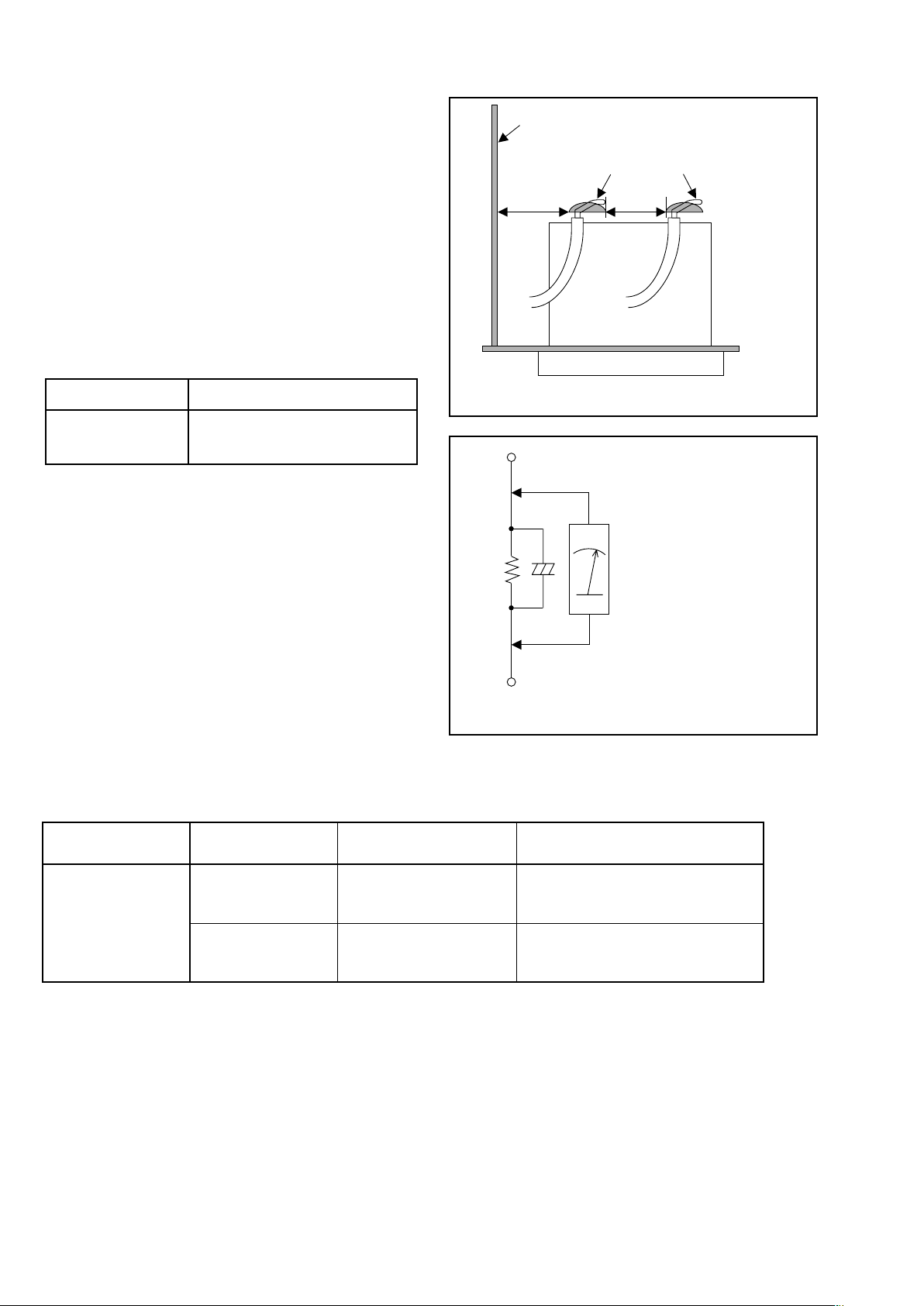
1. Clearance Distance
When replacing primary circuit components, confirm
specified clearance distance (d) and (d’) between soldered terminals, and between terminals and surrounding metallic parts. (See Fig. 1)
Table 1 : Ratings for selected area
Note: This table is unofficial and for reference only.
Be sure to confirm the precise values.
2. Leakage Current Test
Confirm the specified (or lower) leakage current
between B (earth ground, power cord plug prongs)
and externally exposed accessible parts (RF terminals, antenna terminals, video and audio input and
output terminals, microphone jacks, earphone jacks,
etc.) is lower than or equal to the specified value in the
table below.
Measuring Method (Power ON) :
Insert load Z between B (earth ground, power cord
plug prongs) and exposed accessible parts. Use an
AC voltmeter to measure across the terminals of load
Z. See Fig. 2 and the following table.
AC Line Voltage Clearance Distance (d), (d’)
230 V
≥ 3 mm(d)
≥ 6 mm(d’)
Fig. 1
Chassis or Secondary Conductor
Primary Circuit
d' d
AC Voltmeter
(High Impedance)
Exposed Accessible Part
B
One side of
Power Cord Plug Prongs
Z
Fig. 2
Table 2: Leakage current ratings for selected areas
Note: This table is unofficial and for reference only. Be sure to confirm the precise values.
AC Line Voltage Load Z Leakage Current (i)
One side of power cord plug
prongs (B) to:
230 V
2kΩ RES.
Connected in
parallel
i≤0.7mA AC Peak
i≤2mA DC
RF or
Antenna terminals
50kΩ RES.
Connected in
parallel
i≤0.7mA AC Peak
i≤2mA DC
A/V Input, Output
Page 11
9
STANDARD NOTES FOR SERVICING
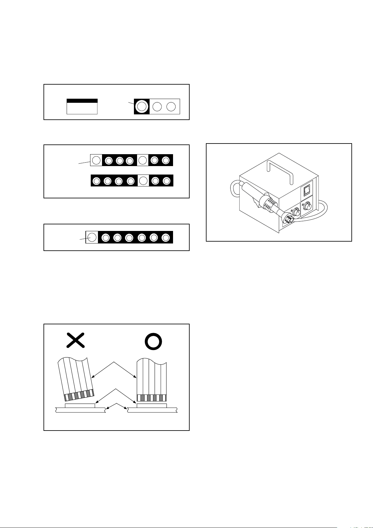
Circuit Board Indications
1. The output pin of the 3 pin Regulator ICs is
indicated as shown.
2. For other ICs, pin 1 and every fifth pin are
indicated as shown.
3. The 1st pin of every male connector is indicated as
shown.
Instructions for Connectors
1. When you connect or disconnect the FFC (Flexible
Foil Connector) cable, be sure to first disconnect
the AC cord.
2. FFC (Flexible Foil Connector) cable should be
inserted parallel into the connector, not at an
angle.
Pb (Lead) Free Solder
When soldering, be sure to use the Pb free solder.
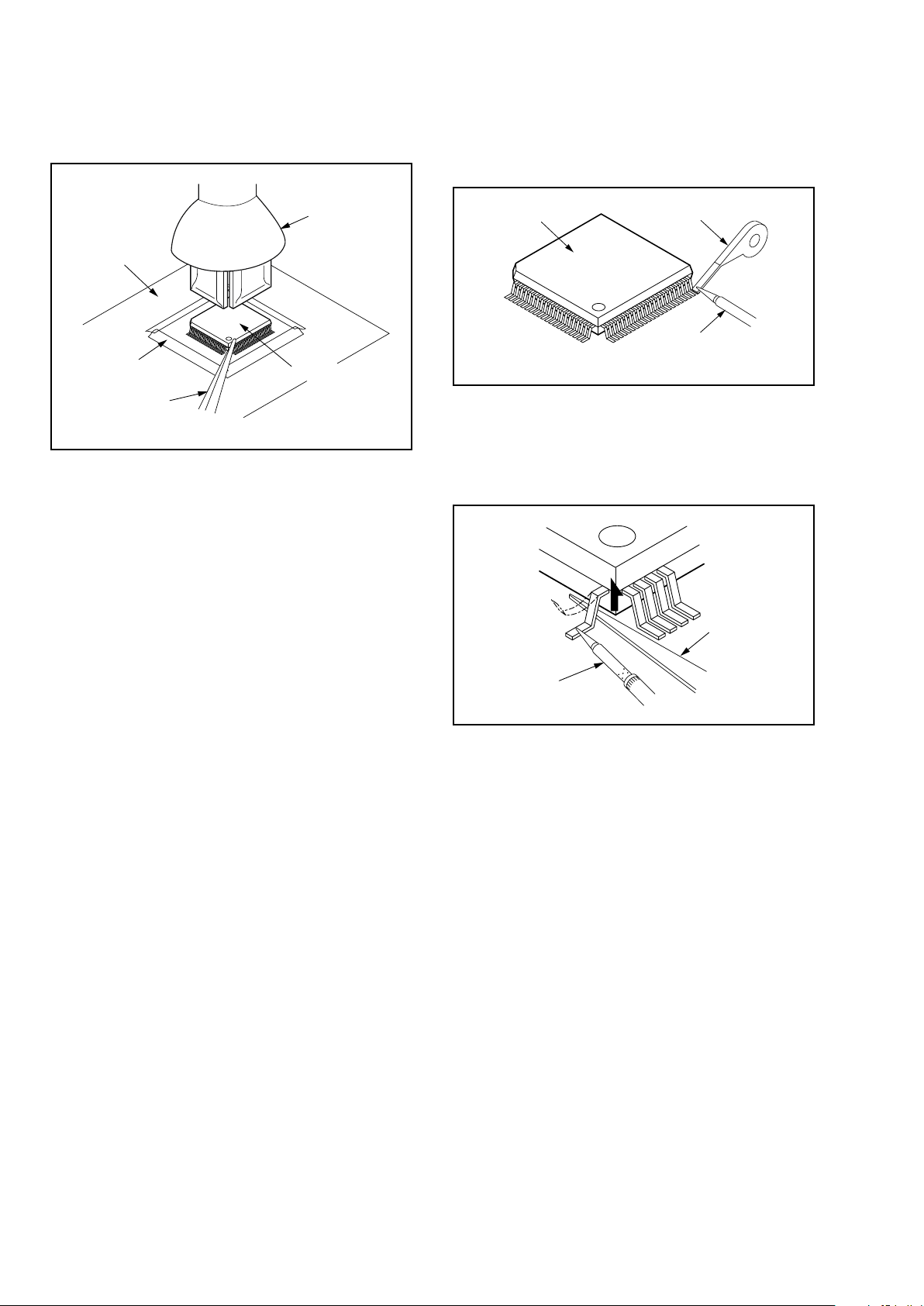
How to Remove / Install Flat Pack-IC
1. Removal
With Hot-Air Flat Pack-IC Desoldering Machine:
1. Prepare the hot-air flat pack-IC desoldering
machine, then apply hot air to the Flat Pack-IC
(about 5 to 6 seconds). (Fig. S-1-1)
2. Remove the flat pack-IC with tweezers while
applying the hot air.
3. Bottom of the flat pack-IC is fixed with glue to the
CBA; when removing entire flat pack-IC, first apply
soldering iron to center of the flat pack-IC and heat
up. Then remove (glue will be melted). (Fig. S-1-6)
4. Release the flat pack-IC from the CBA using
tweezers. (Fig. S-1-6)
CAUTION:
1. The Flat Pack-IC shape may differ by models. Use
an appropriate hot-air flat pack-IC desoldering
machine, whose shape matches that of the Flat
Pack-IC.
2. Do not supply hot air to the chip parts around the
flat pack-IC for over 6 seconds because damage
to the chip parts may occur. Put masking tape
around the flat pack-IC to protect other parts from
damage. (Fig. S-1-2)
Top View
Out
In
Bottom View
Input
5
10
Pin 1
Pin 1
FFC Cable
Connector
CBA
* Be careful to avoid a short circuit.
Fig. S-1-1
STANDARD NOTES FOR SERVICING
Page 12
10
3. The flat pack-IC on the CBA is affixed with glue, so
be careful not to break or damage the foil of each
pin or the solder lands under the IC when
removing it.
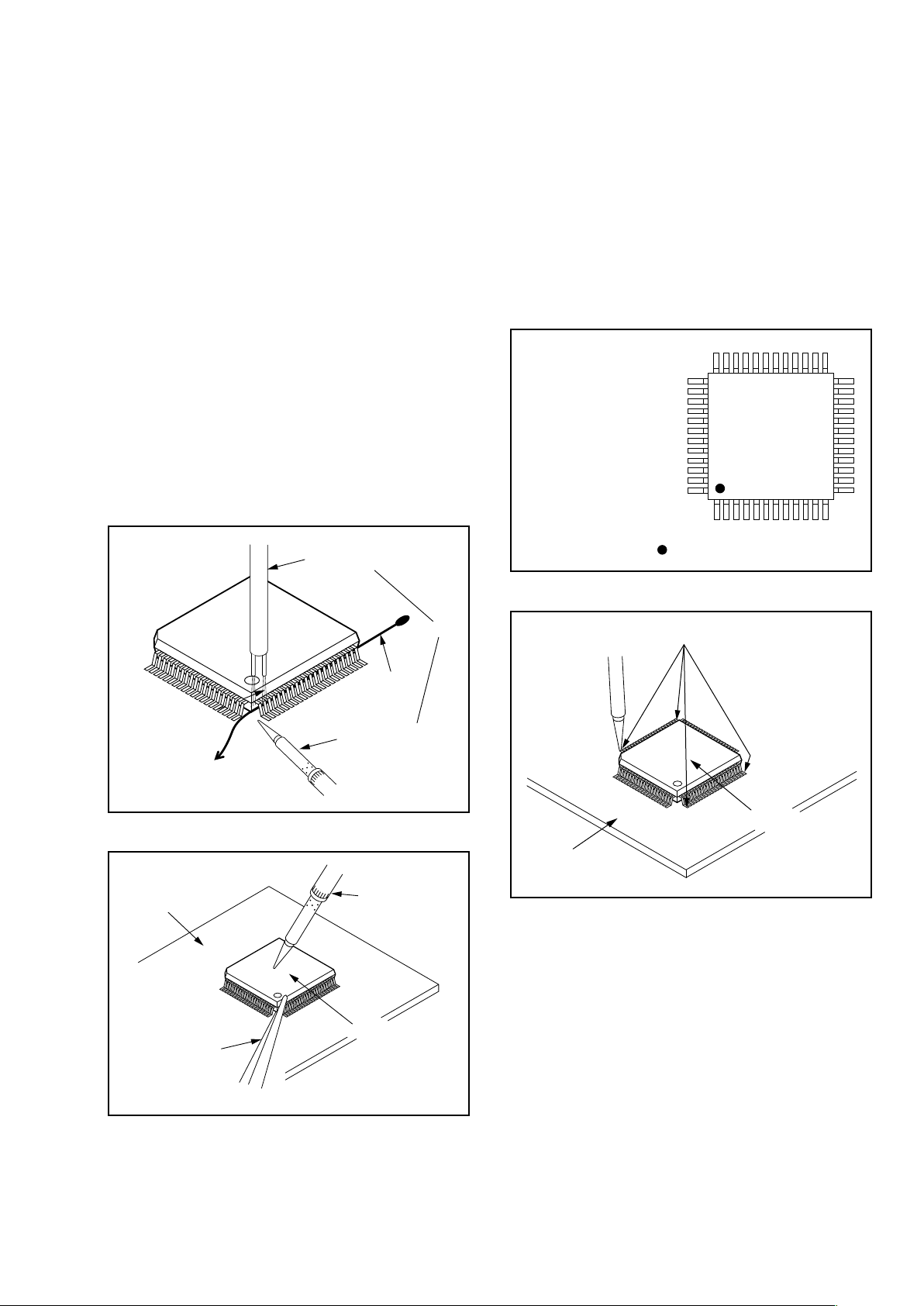
With Soldering Iron:
1. Using desoldering braid, remove the solder from
all pins of the flat pack-IC. When you use solder
flux which is applied to all pins of the flat pack-IC,
you can remove it easily. (Fig. S-1-3)
2. Lift each lead of the flat pack-IC upward one by
one, using a sharp pin or wire to which solder will
not adhere (iron wire). When heating the pins, use
a fine tip soldering iron or a hot air desoldering
machine. (Fig. S-1-4)
3. Bottom of the flat pack-IC is fixed with glue to the
CBA; when removing entire flat pack-IC, first apply
soldering iron to center of the flat pack-IC and heat
up. Then remove (glue will be melted). (Fig. S-1-6)
4. Release the flat pack-IC from the CBA using
tweezers. (Fig. S-1-6)
Hot-air
Flat Pack-IC
Desoldering
Machine
CBA
Flat Pack-IC
Tweezers
Masking
Tape
Fig. S-1-2
Flat Pack-IC
Desoldering Braid
Soldering Iron
Fig. S-1-3
Fine Tip
Soldering Iron
Sharp
Pin
Fig. S-1-4
Page 13
11
With Iron Wire:
1. Using desoldering braid, remove the solder from
all pins of the flat pack-IC. When you use solder
flux which is applied to all pins of the flat pack-IC,
you can remove it easily. (Fig. S-1-3)
2. Affix the wire to a workbench or solid mounting
point, as shown in Fig. S-1-5.
3. While heating the pins using a fine tip soldering
iron or hot air blower, pull up the wire as the solder
melts so as to lift the IC leads from the CBA
contact pads as shown in Fig. S-1-5.
4. Bottom of the flat pack-IC is fixed with glue to the
CBA; when removing entire flat pack-IC, first apply
soldering iron to center of the flat pack-IC and heat
up. Then remove (glue will be melted). (Fig. S-1-6)
5. Release the flat pack-IC from the CBA using
tweezers. (Fig. S-1-6)
Note: When using a soldering iron, care must be
taken to ensure that the flat pack-IC is not
being held by glue. When the flat pack-IC is
removed from the CBA, handle it gently
because it may be damaged if force is applied.
2. Installation
1. Using desoldering braid, remove the solder from
the foil of each pin of the flat pack-IC on the CBA
so you can install a replacement flat pack-IC more
easily.
2. The “�” mark on the flat pack-IC indicates pin 1.
(See Fig. S-1-7.) Be sure this mark matches the 1
on the PCB when positioning for installation. Then
presolder the four corners of the flat pack-IC. (See
Fig. S-1-8.)
3. Solder all pins of the flat pack-IC. Be sure that
none of the pins have solder bridges.
To Solid
Mounting Point
Soldering Iron
Iron Wire
or
Hot Air Blower
Fig. S-1-5
Fine Tip
Soldering Iron
CBA
Flat Pack-IC
Tweezers
Fig. S-1-6
Example :
Pin 1 of the Flat Pack-IC
is indicated by a " " mark.
Fig. S-1-7
Presolder
CBA
Flat Pack-IC
Fig. S-1-8
Page 14
12
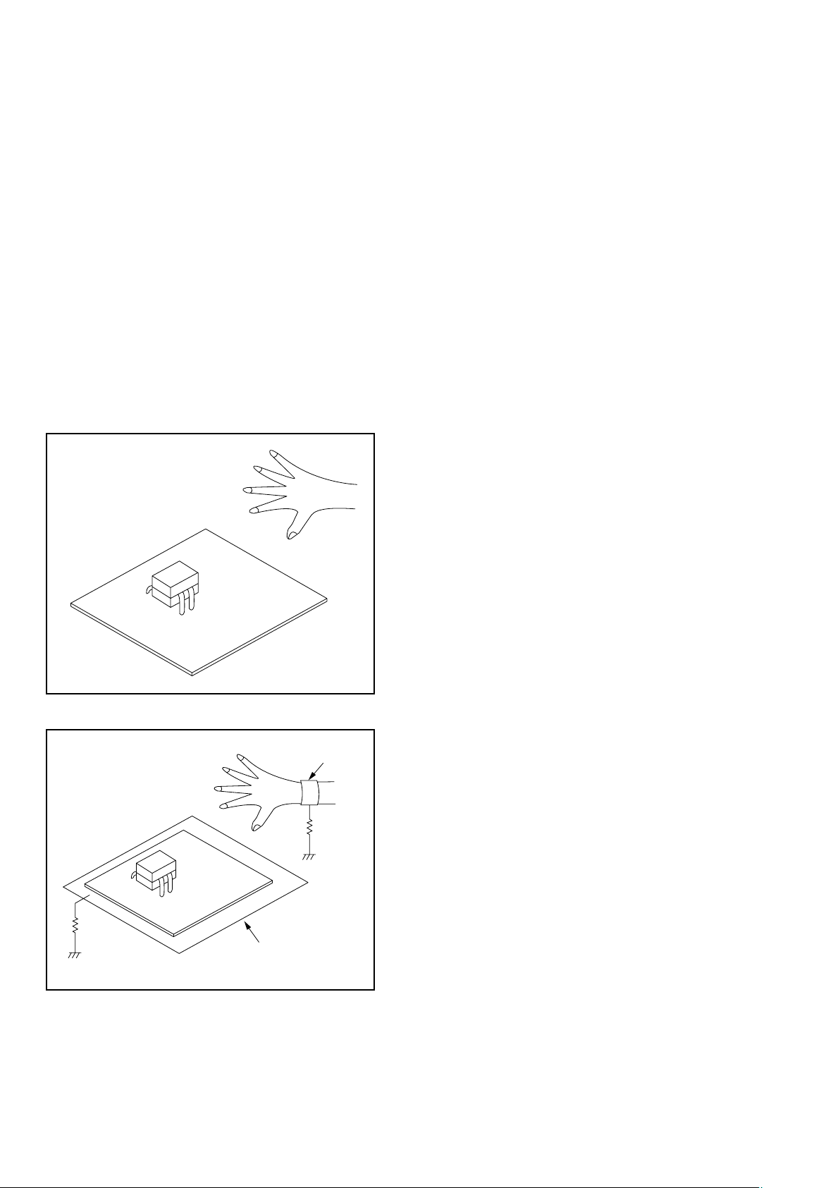
Instructions for Handling Semiconductors
Electrostatic breakdown of the semi-conductors may
occur due to a potential difference caused by
electrostatic charge during unpacking or repair work.
1. Ground for Human Body
Be sure to wear a grounding band (1 MΩ) that is
properly grounded to remove any static electricity that
may be charged on the body.
2. Ground for Workbench
Be sure to place a conductive sheet or copper plate
with proper grounding (1 MΩ) on the workbench or
other surface, where the semi-conductors are to be
placed. Because the static electricity charge on
clothing will not escape through the body grounding
band, be careful to avoid contacting semi-conductors
with your clothing.
<Incorrect>
CBA
Grounding Band
Conductive Sheet or
Copper Plate
1MΩ
1MΩ
<Correct>
CBA
Page 15
13
CABINET DISASSEMBLY INSTRUCTIONS
1. Disassembly Flowchart
This flowchart indicates the disassembly steps to gain
access to item(s) to be serviced. When reassembling,
follow the steps in reverse order. Bend, route, and
dress the cables as they were originally.
2. Disassembly Method
Note:
(1) Identification (location) No. of parts in the figures
(2) Name of the part
(3) Figure Number for reference
(4) Identification of parts to be removed, unhooked,
unlocked, released, unplugged, unclamped, or
desoldered.
P = Spring, L = Locking Tab, S = Screw,
CN = Connector
* = Unhook, Unlock, Release, Unplug, or Desolder
e.g. 2(S-2) = two Screws (S-2),
2(L-2) = two Locking Tabs (L-2)
(5) Refer to “Reference Notes.”
About tightening screws
When tightening screws, tighten them with the
following torque.
Reference Notes
1. CAUTION 1: Locking Tabs (L-1) ,(L-2) and (L-3)
are fragile. Be careful not to break them.
2. The FE Main CBA & BD Mechanism Assembly is
adjusted as a unit at factory. Therefore, do not
disassemble it. Replace the FE Main CBA & BD
Mechanism Assembly as a unit.
ID/
Loc.
No.
Part
Removal
Fig.
No.
Remove/*Unhook/
Unlock/Release/
Unplug/Desolder
Note
[1] Top Cover D1 6(S-1) --[2] Tray Panel D2 *2(L-1) 1
[3]
Front
Assembly
D2
*5(L-2), *3(L-3), (S-2),
*CN2001
1
[4] Front CBA D2 3(S-3), *CN3001 ---
[5]
Power SW
CBA
D2 (S-4), PCB Cover ---
[6]
FE Main
CBA & BD
Mechanism
Assembly
D3
4(S-5), *CN2601,
*CN6401
2
[7]
BE Main
CBA Unit
D3
(S-6), (S-7), *CN7001,
*CN7401, *CN7602,
Locking Card
Spacers, Mecha Earth
Plate
---
[8]
Power
Supply CBA
D4
4(S-8), (S-9), 2(S-10),
*CN2600, Power PCB
Holder
---
[9] Rear Panel D5
3(S-11), 3(S-12),
*CN2004
---
[10]
Motor DC
Fan
D5 2(S-13) ---
[5] Power SW CBA
[3] Front Assembly
[2] Tray Panel
[1] Top Cover
[8] Power Supply CBA
[7] BE Main CBA Unit
[9] Rear Panel
[10] Motor DC Fan
[13] Front Bracket R
[14] BE PCB Holder
Assembly
[6] FE Main CBA &
BD Mechanism Assembly
[11] AV CBA
[4] Front CBA
[12] SD CBA
[11] AV CBA D5 5(S-14), (S-15) ---
[12] SD CBA D5
2(S-16), (S-17),
SD Card Holder
---
[13]
Front
Bracket R
D5 (S-18) ---
[14]
BE PCB
Holder
Assembly
D5 (S-19) ---
↓
(1)
↓
(2)
↓
(3)
↓
(4)
↓
(5)
Torque
0.45 ± 0.05 N·m
ID/
Loc.
No.
Part
Removal
Fig.
No.
Remove/*Unhook/
Unlock/Release/
Unplug/Desolder
Note
CABINET DISASSEMBLY INSTRUCTIONS
Page 16
14
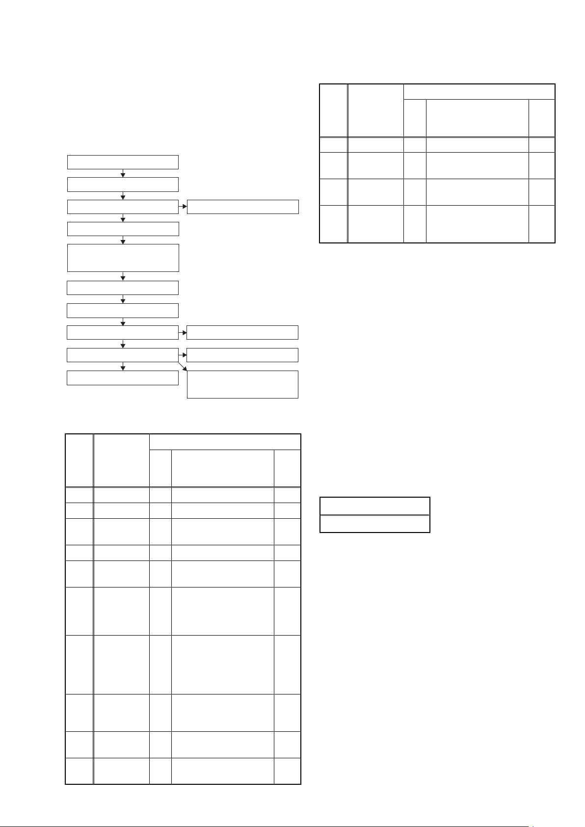
[1] Top Cover
(S-1)
(S-1)
(S-1)
Fig. D1
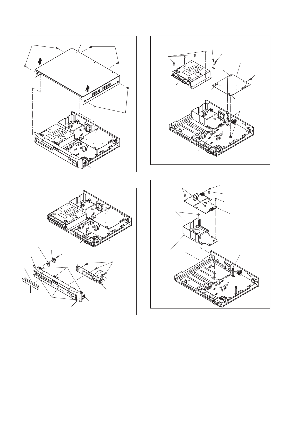
[4] Front CBA
[3] Front Assembly
[2] Tray
Panel
(S-3)
(S-4)
CN2001
(L-2)
(L-2)
(L-2)
(L-3)
CN3001
Wire
[5] Power SW
CBA
(S-2)
PCB Cover
(L-1)
Fig. D2
[7] BE Main CBA
Unit
[6] FE Main
CBA& BD
Mechanism
Assembly
CN7001
CN7401
CN2601
CN7602
CN6401
(S-6)
(S-7)
Locking Card
Spacers
(S-5)
Mecha Earth Plate
Fig. D3
Fig. D4
[8] Power
Supply CBA
(S-9)
CN2600
Power PCB
Holder
(S-10)
(S-8)
(S-8)
(S-8)
Page 17
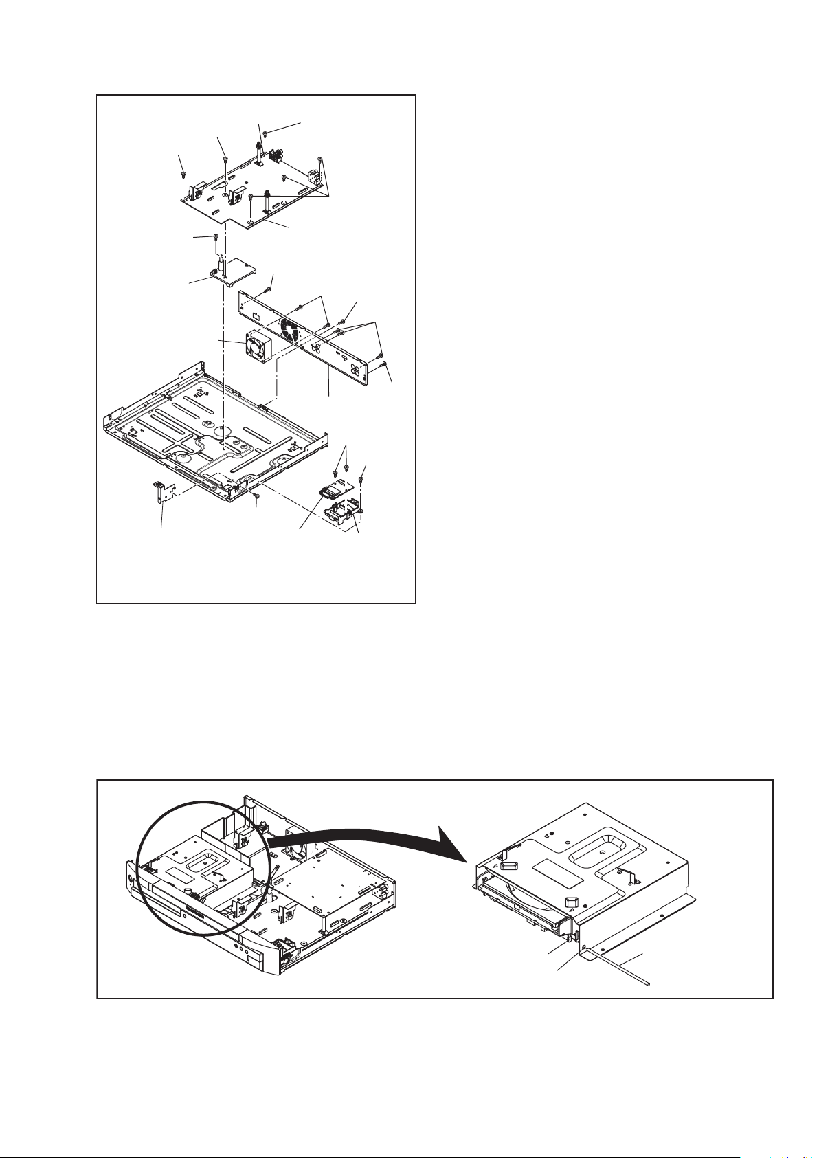
15
[11] AV CBA
[9] Rear Panel
[12] SD CBA
(S-18)
(S-16)
(S-17)
SD Card
Holder
(S-14)
(S-15)
CN2004
(S-14)
(S-14)
[10] Motor DC Fan
[14] BE PCB
Holder Assembly
[13] Front
Bracket R
(S-12)
(S-11)
(S-11)
(S-13)
(S-11)
(S-19)
Fig. D5
3. How to Eject Manually
1. Remove the Top Cover.
2. Insert a screwdriver, etc. into the Hole A straightly so that the Portion A is pushed.
3. Pull the tray out manually and remove a disc.
Screwdriver,
hexagon wrench
Hole A
Portion A
3. How to Eject Manually
Page 18
16
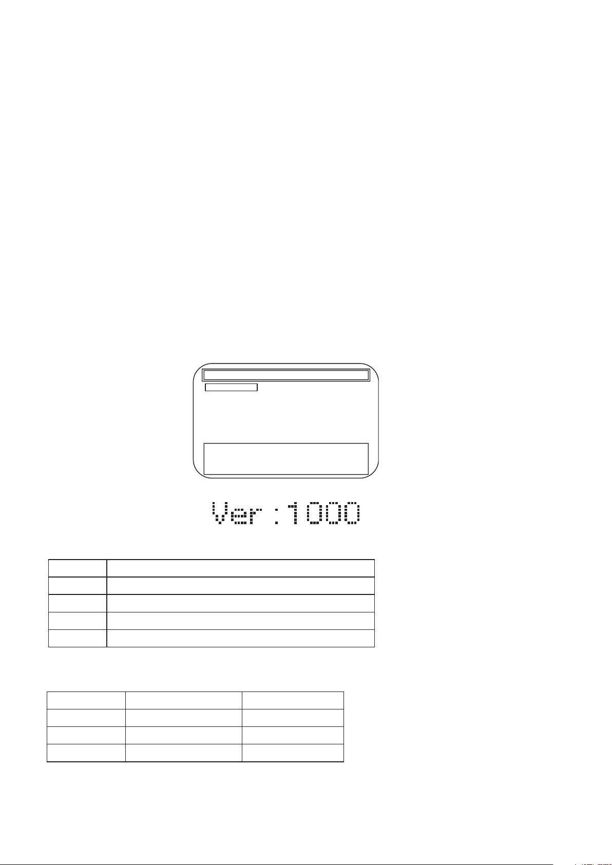
HOW TO INITIALIZE THE BLU-RAY DISC PLAYER
To put the program back at the factory-default,
initialize the BD player as the following procedure.
1. Turn the power on.
2. Remove the disc on the tray and close the tray.
3. Press [1], [2], [3], [4], and [DISPLAY] buttons on
the remote control unit in that order.
Fig. a appears on the screen.
4. Press [STOP] button on the remote control unit.
Fig. b appears on the screen and Fig. c appears
on the VFD.
5. To exit this mode, press [POWER OFF] button.
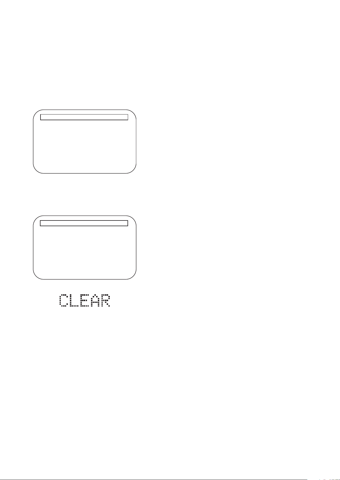
Fig. a
"
*******
" differ depending on the models.
Model Name
Version
Region
Version Info
: *******
: *.***
: *-*
EXIT <POWER>EEPROM CLEAR <STOP>
Fig. b
"
*******
" differ depending on the models.
Model Name
Version
Region
Version Info
: *******
: *.***
: *-*
EXIT <POWER>EEPROM CLEAR <STOP>
EEPROM CLEAR : OK
Fig. c
HOW TO INITIALIZE THE BLU-RAY DISC PLAYER
Page 19

17
TRAY LOCK MODE
Tray Lock Mode prevents the tray opening or closing to
prevent disc theft in demo mode.
Enter this mode using the following procedure.
1. Confirm that the TV Monitor is connected.
2. With playback stopped, press [SETUP], [TOP
MENU], [3], [AUDIO], [0] and [SETUP] buttons on
the remote control unit in that order. "Trade-On"
appears in the upper right corner on the screen,
and Fig. a appears on the VFD for 2 seconds.
3. To exit this mode, press [SETUP], [TOP MENU],
[3], [AUDIO], [0] and [SETUP] buttons on the
remote control unit in that order. "Trade-Off"
appears in the upper right corner on the screen,
and Fig. b appears on the VFD for 2 seconds.
Fig. a
Fig. b
TRAY LOCK MODE
Page 20
18
Entering Service Mode
In power on condition, no discs and tray close, it will be entered into service mode by the following operation using
the remote controller. However, it will not be entered when Media Select Item is SD Memory.
Service Mode by using remote controller
Press the following buttons on the remote controller in power on condition, no discs and tray close;
[2]->[5]->[8]->[0]->[CLEAR]
Release from Service Mode
Press the [POWER OFF] button to turn off power.
Screen saver/Auto Power Off in Service Mode
These functions are not performed in Service Mode.
After entering, Fig. k appears on the screen and Fig. l appears on the VFD.
Available button in service mode
Note:Press the number key to select items. Or, press the cursor button (up/down) to select items and press
[ENTER] button.
Button condition
ENTER Enter the next level
POWER Turn the power off (when the service mode is completed)
1~8 Enter the selected item (next level)
OTHER Not available
INDICATION DESCRIPTION REMARK
Model Name Model Name E5J***D, etc.
Region BD region - DVD region A-1, etc.
Release Ver. Release version D.jpp, etc.
Service Mode
1. Mecha Test
2. VFD/LED Test
3: Error Rate
4: LD Test
5: RS-232C
6: Channel Test
7: SD Card Test
8: Default Setting
Model Name: :E5J***D Region :A-1
Release Ver. :*.***
ADSP1/2 Ver. :****/**** PLD Ver. :*
FPGA Ver. :** I/P Scaler Ver.:********
Fig. k Service Mode (Main menu)
* Firmware Version differs depending on the
models, and this indication is one example.
Fig. l Service Mode
Entering Service Mode
In power on condition, no discs and tray close, it will be entered into service mode by the following operation using
the remote controller. However, it will not be entered when Media Select Item is SD Memory.
Service Mode by using remote controller
Press the following buttons on the remote controller in power on condition, no discs and tray close;
[2]->[5]->[8]->[0]->[CLEAR]
Release from Service Mode
Press the [POWER OFF] button to turn off power.
Screen saver/Auto Power Off in Service Mode
These functions are not performed in Service Mode.
After entering, Fig. k appears on the screen and Fig. l appears on the VFD.
Service Mode
1. Mecha Test
2. VFD/LED Test
3: Error Rate
4: LD Test
5: RS-232C
6: Channel Test
7: SD Card Test
8: Default Setting
Model Name: :E5J***D Region :A-1
Release Ver. :*.***
ADSP1/2 Ver. :****/**** PLD Ver. :*
FPGA Ver. :** I/P Scaler Ver.:********
Fig. k Service Mode (Main menu)
* Firmware Version differs depending on the
models, and this indication is one example.
SERVICE MODE
Button Condition
ENTER Enter the next level
POWER Turn the power off (when the service mode is completed)
1~8 Enter the selected item (next level)
OTHER Not available
Indication Description Remark
Model Name Model Name E5J***D, etc.
Region BD region - DVD region A-1, etc.
Release Ver. Release version D.jpp, etc.
Page 21
19
Available test in service mode
1st level 2nd level 3rd level Description
1 Tray Aging Aging of tray open/close
1 Mecha test
2 VFD/LED Test
3 Error Rate
4 LD Test
5 Channel Test
2 TOC Read TOC reading
3 Heat Run
Tray close -> TT1 playback -> TT10
playback -> Tray open -> Tray close
1 All On Turning on all VFD
2 All Off Turning off all VFD
Displaying Error rate, Jitter during
playback
1 Off Turning off LD
2 BD Turning on BD LD
1 LD Power
3 DVD Turning on DVD LD
4 CD Turning on CD LD
2 Operating Time
Center/ Subwoofer/
1
Front LR
Displaying LD Operation Time
(with clear function)
1 TEST TONE
Surround LR/
2
Surround Back LR
2 Front Lch
3 Center
4 Front Rch
5 Surround Rch
6 Surround Back Rch
7 Surround Back Lch
8 Surround Lch
9 Sub woofer
1 Even Setting even parity
1 Parity Setting
6 RS-232C
2 Version Up Mode
2 Non Setting non parity
Realta Version up with connecting
RS-232C
7 SD Card Test
8 Default Setting Default setting
Note : If some test are performed continuously, any error will occur.
Page 22
20
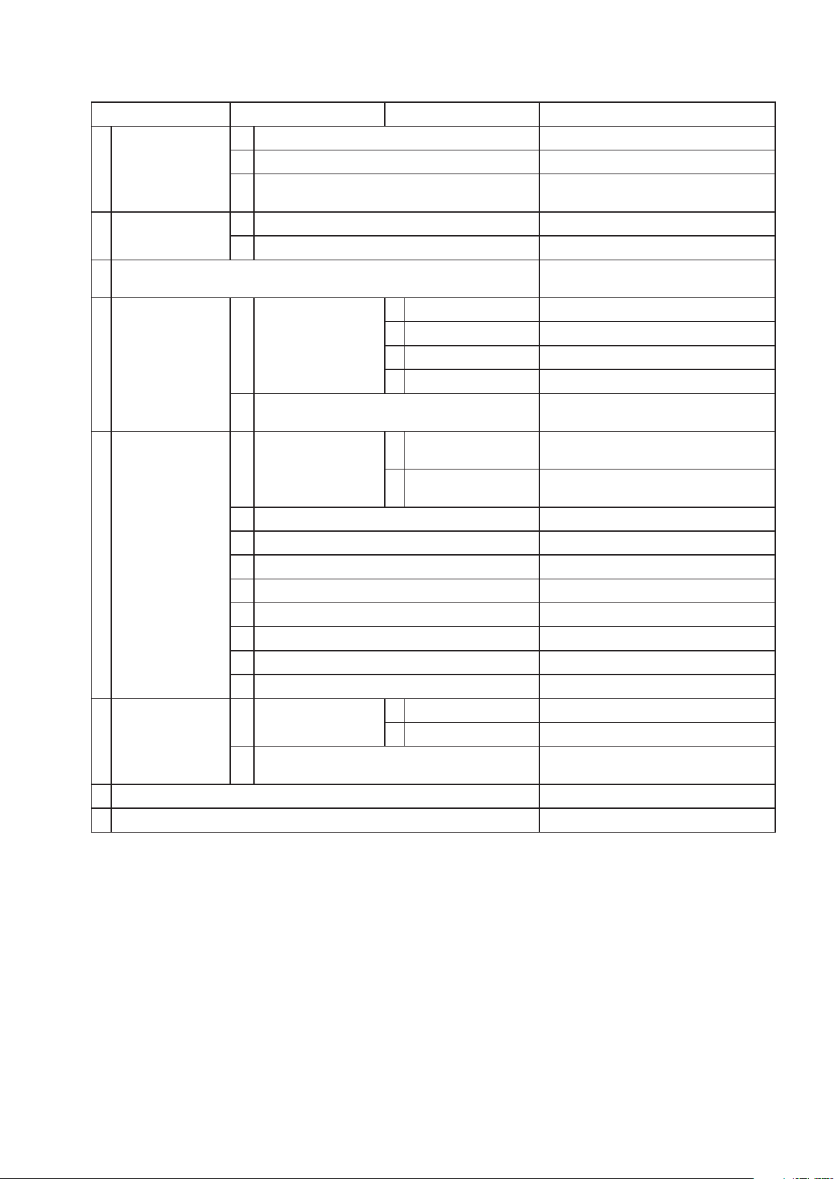
FIRMWARE RENEWAL MODE
1. Turn the power on and remove the disc on the tray.
2. To put the BD player into version up mode, press
[9], [8], [7], [6], and [POP UP MENU/MENU]
buttons on the remote control unit in that order.
The tray will open automatically.
Fig. a appears on the screen and Fig. b appears
on the VFD.
The BD player can also enter the version up mode
with the tray open. In this case, Fig. a will be
shown on the screen while the tray is open.
3. Load the disc for version up.
4. The BD player enters the F/W version up mode
automatically. Fig. c appears on the screen and
Fig. d appears on the VFD. If you enter the F/W for
different models, “Disc Error” will appear on the
screen, then the tray will open automatically.
The appearance shown in (*1) of Fig. c is
described as follows:
5. After programming is finished, the checksum on
the VFD (Fig. f).
At this time, no button is available.
6. Unplug the AC cord from the AC outlet. Then plug
it again.
7. Turn the power on.
8. Press [1], [2], [3], [4], and [DISPLAY] buttons on
the remote control unit in that order.
Fig. g appears on the screen.
F/W VERSION UP MODE Model No. ******* Ver. *.***
Please insert a Disc
for F/W Version Up
"
*******
" differs depending on the models.
Fig. a Version Up Mode Screen
Fig. b VFD in Version Up Mode
1. ALL
Now Loading...
Ver. : *.** ************B*.bin
(*1)
F/W VERSION UP MODE Model No : ******* Ver. : *.***
ADSP 1/2 Ver. : ***/***
"
*******
" differs depending on the models.
Fig. c Programming Mode Screen (Example
)
Fig. d VFD in Programming Mode (Example)
No. Appearance State
1 Now Loading... Loading the disc
2 Reading...
Sending files into the
memory.
After reading, automatically
the tray opens.
3
Remove the
disc
Reading has finished.
Remove the disc and close
the tray.
4 See FL display
Writing new version data,
the progress will be displayed
as shown in Fig. e.
Fig. e VFD in Version Up Mode
Fig. f VFD upon Finishing the Programming Mode (Example)
Fig. g
"
*******
" differ depending on the models.
Model Name
Version
Region
Version Info
: *******
: *.***
: *-*
EXIT <POWER>EEPROM CLEAR <STOP>
FIRMWARE RENEWAL MODE
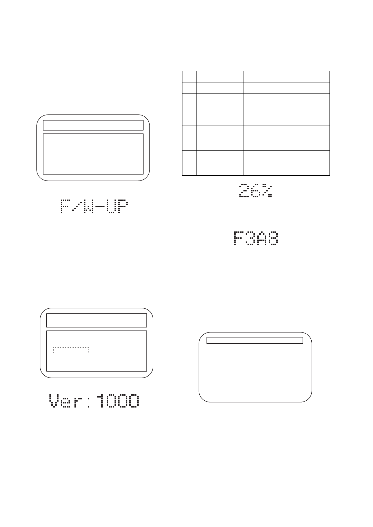
Page 23

21
9. Press [STOP] button on the remote control unit.
Fig. h appears on the screen and Fig. i appears on
the VFD.
10. To exit this mode, press [POWER OFF] button.
How to Verify the Firmware Version
1. Turn the power on.
2. Remove the disc on the tray and close the tray.
3. Press [1], [2], [3], [4], and [DISPLAY] buttons on
the remote control unit in that order.
Fig. j appears on the screen.
4. To exit this mode, press [POWER OFF] button.
Fig. h
"
*******
" differ depending on the models.
Model Name
Version
Region
Version Info
: *******
: *.***
: *-*
EXIT <POWER>EEPROM CLEAR <STOP>
EEPROM CLEAR : OK
Fig. i
Fig.
j
"
*******
" differ depending on the models.
Model Name
Version
Region
Version Info
: *******
: *.***
: *-*
EXIT <POWER>EEPROM CLEAR <STOP>
How to Verify the Firmware Version
1. Turn the power on.
2. Remove the disc on the tray and close the tray.
3. Press [1], [2], [3], [4], and [DISPLAY] buttons on
the remote control unit in that order.
Fig. j appears on the screen.
4. To exit this mode, press [POWER OFF] button.
Fig.
j
"
*******
" differ depending on the models.
Model Name
Version
Region
Version Info
: *******
: *.***
: *-*
EXIT <POWER>EEPROM CLEAR <STOP>
How to Verify the Firmware Version
Page 24
22
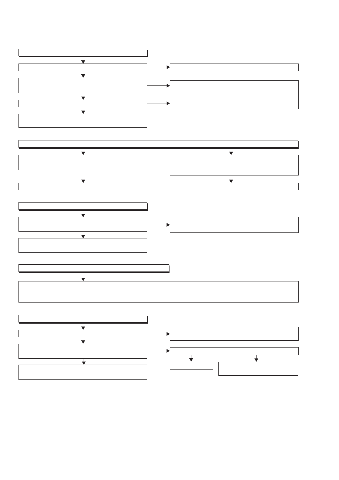
TROUBLESHOOTING
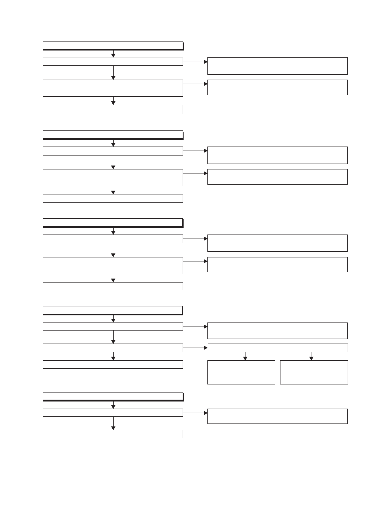
FLOW CHART NO.2
The fuse blows out.
After servicing, replace the fuse.
Check the presence that the primary component
is leaking or shorted and service it if defective.
Check the presence that the rectifying diode or
circuit is shorted in each rectifying circuit of
secondary side, and service it if defective.
FLOW CHART NO.3
When the output voltage fluctuates.
Ye s
No
FLOW CHART NO.4
When buzz sound can be heard in the vicinity of power circuit.
Check if there is any short-circuit on the rectifying diode and the circuit in each rectifying circuit of the secondary
side
, and service it if defective.
(D1010, D1011, D1013, D1014, D1015, D1016, D1018, D1023, IC2600, IC2601,
Q2603, Q2604, Q2606, Q2607)
Does the photo coupler circuit on the secondary
side operate normally?
Check IC1001, IC1003, D1006 and their periphery,
and service it if defective.
Check IC1003, D1009 and their periphery,
and service it if defective.
FLOW CHART NO.5
FL is not outputted.
Is 34.5V voltage supplied to the emitter of Q2012?
Check D1018, C1021 and periphery circuit,
and service it if defective.
Check FL-SW line and service
it if defective.
Is the "L" signal outputted to the collector of
Q2013?
Ye s
Ye s
Ye s
No
No
No
FLOW CHART NO.1
The power cannot be turned on.
Is the fuse normal?
Is normal state restored when once unplugged
power cord is plugged again after several seconds?
Is the AL+5V line voltage normal?
See FLOW CHART No.2 <The fuse blows out.>
Check if there is any leak or short-circuiting on the
primary circuit component, and service it if defective.
(IC1001,Q1003, T1001, D1001, D1002, D1003,
D1004, D1007, D1008, C1010, R1013)
Check each rectifying circuit of the secondary circuit
and service it if defective.
Ye s
Ye s
Ye s
No
No
No
Check Q2012, D2001
and their periphery,
and service it if defective.
Is the "H" signal inputted to the base of Q2013?
Replace Q2013.
TROUBLESHOOTING
Page 25
23
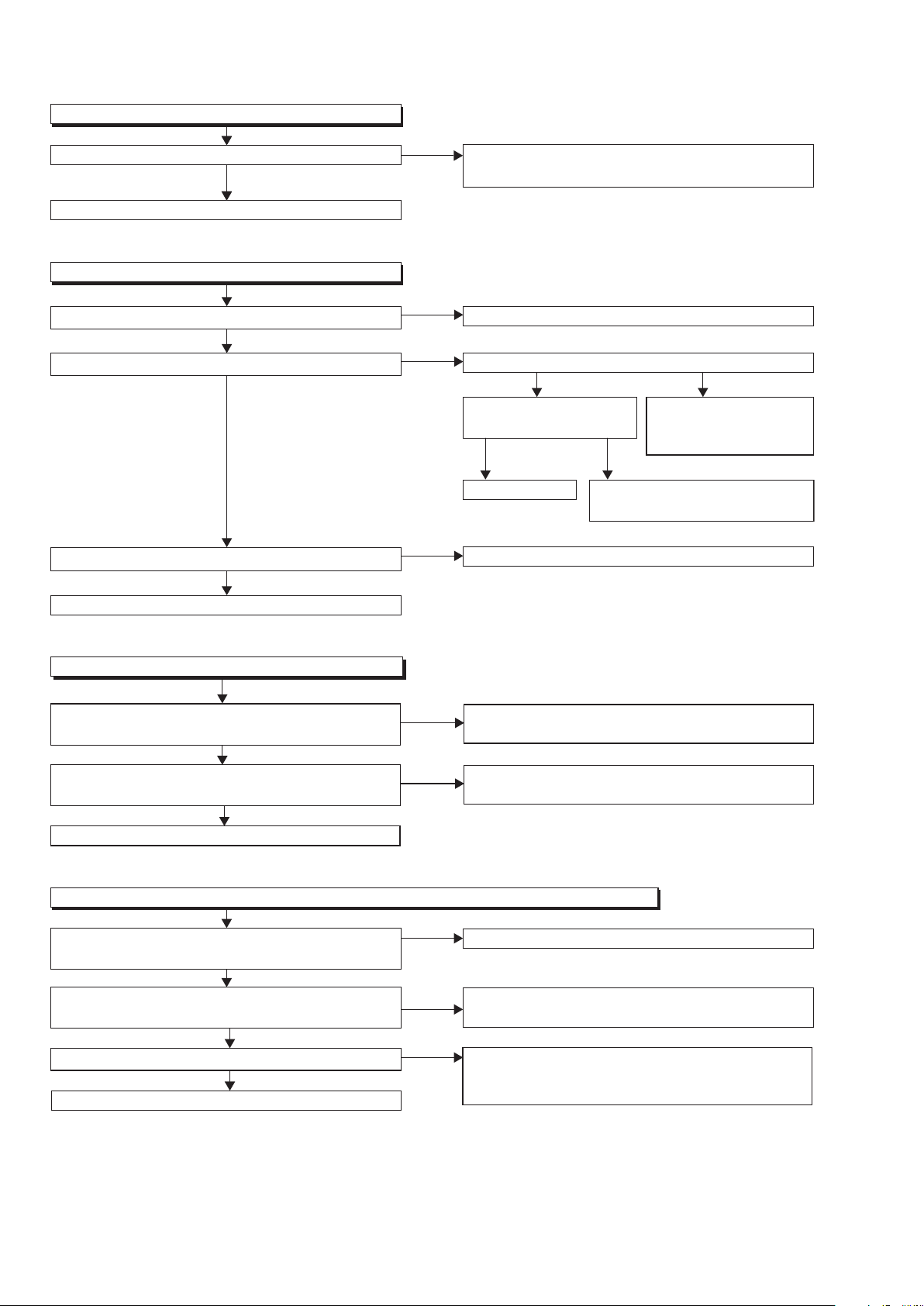
FLOW CHART NO.7
P-ON+5V (1) is not outputted.
Is 5V voltage inputted to the emitter of Q2606?
Replace Q2607.
Ye s
No
Is 11V voltage inputted to the base of Q2607? Is 12V voltage inputted to the base of Q2602?
Check D1020, D1023, C1018, C1024, L1003
and
their periphery, and service it if defective.
No
FLOW CHART NO.8
FLOW CHART NO.9
P-ON+10.5V is not outputted.
Is 13V voltage inputted to the collector of Q2607?
Ye s Ye s No
Ye s
Check D1016, C1020
and the periphery circuit,
and service it if defective.
Check Q2602, D2606,
and their periphery, and
service it if defective.
Check Q2601, D2613,
and PWSW3 line, and
service it if defective.
Is 2.5V voltage supplied to Pin(1) of IC2601?
Ye s
No
FLOW CHART NO.10
P-ON+1.2V is not outputted.
Replace IC2601.
FLOW CHART NO.6
P-ON+12V is not outputted.
Is 12V voltage supplied to the emitter of Q2603?
Is the voltage of base on Q2603 lower than the
voltage of emitter on Q2603 when turning the power on?
Replace Q2603.
Check D1011, D1019, C1017, L1005 and
their periphery circuit, and service it if defective.
Check Q2601 and PWSW3 line and service it if
defective.
Ye s
Ye s
No
No
Is the voltage of base on Q2606 lower than the
voltage of emitter on Q2606 when turning the power on?
Replace Q2606.
Check Q2605 and PWSW3 line and service it if
defective.
Ye s
No
Check D1013, D1014, D1015, C1019, C1025,
and their periphery, and service it if defective.
Check D1013, D1014, D1015, C1019, C1025,
and their periphery, and service it if defective.
Is 5V voltage inputted to the emitter of Q2604?
Ye s
No
Is the voltage of base on Q2604 lower than the
voltage of emitter on Q2604 when turning the power on?
Replace Q2604.
Check Q2605 and PWSW3 line and service it if
defective.
Ye s
No
No
P-ON+5V (2) is not outputted.
Page 26
24
Ye s
No
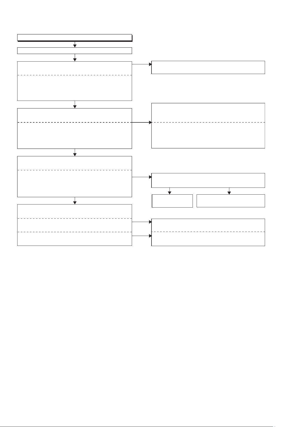
FLOW CHART NO.13
The key operation is not functioning.
Are the contact point and the installation state of the key
switches (SW3100, SW3002-3005) normal?
When pressing each switches (
SW3100, SW3002-3005
),
do the voltage of Pin(4) of IC2000 increase?
Check the switches (
SW3100, SW3002-3005
) and
their periphery, and service it if detective.
Check the line between the
RS3000 (remote control
receiver)
and the
Pin(27) of IC2000,
and service it if
detective.
No
Re-install the switches (
SW3100, SW3002-3005
)
correctly or replace the poor switch.
Replace IC2000.
Ye s
FLOW CHART NO.14
No operation is possible from the remote control unit.(Operation is possible from the unit.)
Replace the RS3000 (remote control receiver) or
remote control unit.
Is the "L" pulse sent out Pin(1) of RS3000 (remote
control receiver) when the remote control unit is activated?
Is the "H" pulse inputted to the Pin(27) of IC2000?
Replace IC2000.
Is 5V voltage supplied to Pin(2) of RS3000
(remote control receiver) ?
Ye s
No
Check AL+3.3V line and service it if defective.
No
No
Ye s
Ye s
Ye s
Ye s
Ye s No
Ye s No
Ye s
No
No
No
FLOW CHART NO.12
The fluorescent display tube does not light up.
Is 3.3V voltage supplied to Pin(24) of FL3000?
Is 8V voltage supplied to Pin(1,2) of FL3000?
Is 5V voltage supplied to Pins(29,30) of FL3000?
Replace FL3000.
Check P-ON+3.3V line and service it if defective.
Is 10V voltage supplied to the emitter of Q2014?
Check D1010, C1016,
R1018 and their periphery,
and service it if defective.
Check Q2013 and FL-SW
line
and service it if defective.
Replace Q2014.
Is 9V voltage inputted
to the base of Q2014?
Check F2
line and service it if defective.
FLOW CHART NO.11
P-ON+3.3V is not outputted.
Is 5V voltage supplied to Pin(1) of IC2600?
Replace IC2600.
Check D1013, D1014, D1015, D1021, C1025
and their periphery circuit, and service it if defective.
Ye s
No
Page 27

25
Ye s
FLOW CHART NO.16
The disc tray cannot be opened and closed.
[No Disc] indicated.
Both functions of picture and sound do not operate normally.
Replace the BE Main CBA Unit.
Original BE Main CBA Unit is poor.
Replace the FE Main CBA & BD Mechanism
Assembly.
No improvement can be found.
No
Ye s
FLOW CHART NO.15
The disc tray cannot be opened and closed. (It can be done using the remote control unit.)
Is the normal control voltage inputted to Pin(4) of
IC2000?
Refer to "FLOW CHART NO.13" <The key
operation is not functioning.>
Refer to "FLOW CHART NO.16" <The disc tray
cannot be opened and closed.>
Replace the "OPEN/CLOSE" switch (SW3005).
No
Page 28
26
Is 5V voltage supplied to the Pin(4,18) of IC2300
and Pin(4) of IC2301?
Replace IC2300
or IC2301.
Check P-ON+5V(2) line and
service it if detective.
Are the video signals outputted to each pin
of IC2300 or IC2301?
Ye s
No
Ye s
Ye s
No
IC2300 20PIN VIDEO-Y(I/P)
IC2300 17PIN VIDEO-Pb/Cb
IC2300 15PIN VIDEO-Pr/Cr
IC2301 5PIN VIDEO-CVBS
Check the periphery of JK2300 from Pin(15,17,20)
of IC2300 and service it if detective.
Check
the periphery of
JK2300 from Pin(5) of
IC2301
and service it if detective.
Are the video signals outputted to the specific
output terminal?
Are the component video signals outputted to the
VIDEO OUT terminal (JK2300)?
No
No
Are the composite video signals outputted to
the VIDEO OUT terminal (JK2300)?
FLOW CHART NO.17
Picture does not appear normally.
Set the disc on the disc tray, and playback.
Are the video signals outputted to each pin of
CN2000?
Replace the BE Main CBA Unit or
FE Main CBA &
BD Mechanism Assembly.
Check the line between each pin of CN2000 and
each pin of IC2300 or IC2301, and service
it if detective.
CN2000 9PIN → IC2301 3PIN VIDEO
CN2000 1PIN → IC2300 1PIN VIDEO-Y(I/P)
CN2000 3PIN → IC2300 3PIN VIDEO-Pb/Cb
CN2000 5PIN → IC2300 5PIN VIDEO-Pr/Cr
Are the video signals shown above inputted into
each pin of IC2300 or IC2301?
Ye s
No
No
CN2000 9PIN VIDEO
CN2000 1PIN VIDEO-Y(I/P)
CN2000 3PIN VIDEO-Pb/Cb
CN2000 5PIN VIDEO-Pr/Cr
IC2301 3PIN VIDEO
IC2300 1PIN VIDEO-Y(I/P)
IC2300 3PIN VIDEO-Pb/Cb
IC2300 5PIN VIDEO-Pr/Cr
Page 29
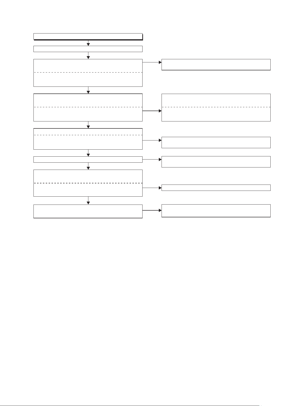
27
FLOW CHART NO.18
Audio is not outputted normally.
Set the disc on the disc tray, and playback.
Is the signal at Pin(31) of IC2000 "H" ?
Are the analog audio signals outputted to each pin
of CN2000?
Is the "H" level mute signal outputted to CN2000 ?
CN2000 27PIN AUDIO(L)
CN2000 25PIN AUDIO(R)
CN2000 23PIN AUDIO(R)-MUTE
CN2000 28PIN AUDIO(L)-MUTE
IC2200 7PIN AUDIO(L)
IC2200 1PIN AUDIO(R)
IC2200 6PIN AUDIO(L)
IC2200 2PIN AUDIO(R)
Replace the BE Main CBA Unit or
FE Main CBA &
BD Mechanism Assembly.
Replace the BE Main CBA Unit or
FE Main CBA &
BD Mechanism Assembly.
Replace IC2200.
Check the periphery between Pin(1,7) of IC2200
and JK2200, and service it if detective.
Check each line between each pin of CN2000
and each pin of IC2200, and service it if detective.
CN2000 27PIN → IC2200 6PIN AUDIO(L)
CN2000 25PIN → IC2200 2PIN AUDIO(R)
Are the analog audio signals inputted to each pin
of IC2200?
Are the analog audio signals outputted to each pin
of IC2200?
Are the audio signals outputted to the audio
terminal (JK2200)?
Ye s
Ye s
Ye s
Ye s
Ye s
No
Check
the AUDIO-MUTE line, and
service it if
detective.
No
No
No
No
No
Page 30
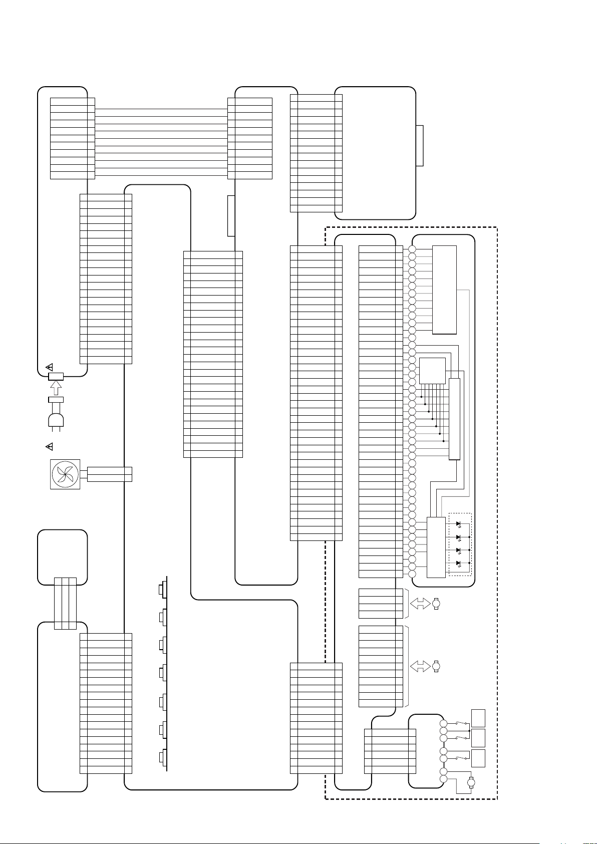
28
WIRING DIAGRAM
FE MAIN CBA & BD MECHANISM ASSEMBLY
AV CBA
FRONT CBA
POWER SW
CBA
POWER SUPPLY CBA
BE MAIN CBA UNIT
FE MAIN CBA
RELAY CBA
PICKUP
SD CBA
CN1002
CN7401
CN6401
CN501
CN101CN902
CN901
CN903
HDMI-CONNECTOR
SD CARD SLOT
28
29
30
GND
31
GND
1
SLD1(-)
2
SLD1(+)
3
SLD2(-)
4
SLD2(+)
32
+3.3V
33
GND-LD
34
GND-LD
35
+5V
36
+8.5V
37
NU
38
SCLK
1
W
2
V
3
U
4
+5V
5
HU(+)
6
HU(-)
7
HV(+)
8
HV(-)
9
HW(+)
10
HW(-)
11
HB(-)
39
SENLDD
40
SD ATA
41
XLDDRST
42
LDEN
43
NU
44
TEST-V
45
NU
1
FD1
2
FR1
3
TD
4
TR
5
FR2
6
FD2
7
EXPA(-)
8
EXPB(-)
9
EXPA(+)
10
EXPB(+)
11
EXPINT
12
PI-CONT
13
14
15
16
17
18
19
20
21
22
23
24
25
26
27
FAN
BD-OEIC
LENS DRIVE
CD/DVD
-OEIC
CD-LD
BD-LD
PD-LD
DVD-LD
LASER DIODE DRIVE
SPINDLE
MOTOR
M
SLED
MOTOR
M
CN7602
CN4002
1
SDDAT2
2
GND
3
SDDAT3
4
GND
5
CMD
6
GND
7
NU
8
D+3.3V
9
D+3.3V
10
GND
11
SDCLK
12
GND
13
SDDAT0
14
GND
15
SDDAT1
16
NU
1
2
3
4
5
6
7
8
9
10
11
12
13
14
15
16
NU
GND
GND
GND
GND
GND
AL+5V
AL+5V
AL+5V
AL+5V
SAFETY
11
10
9
8
7
6
5
4
3
2
1
11
NU
10
GND
9
GND
8
GND
7
GND
6
GND
5
AL+5V
4
AL+5V
3
AL+5V
2
AL+5V
1
SAFETY
CN1001
CN2600
1
AL+2.5V
2
AL+12V(1)
3
AL+5V
4
AL+5V
5
AL+5V
6
EV+3.3V
7
GND
8
GND
9
GND
10
GND
11
GND
12
GND
13
GND
14
GND
15
AL+12V(2)
16
AL+12V(2)
17
AL+12V(2)
18
EV+5V
19
SAFETY
20
F1
21
MAIN-P-ON
22
F2
23
1
2
3
4
5
6
7
8
9
10
11
12
13
14
15
16
17
18
19
20
21
22
23
FL
CN7001
1
VIDEO-Y(I/P)
2
GND
3
VIDEO-Pb/Cb
4
GND
CN3000
CN3001 CN3100
CN2001
1
FL
2
F2
3
F1
4
GND
5
GND
6
AL+3.3V
7
P-ON+3.3V
8
EV+5V
9
NU
10
FL-SDA
11
FL-SCL
12
FL-CS
13
FL-RESET
14
REMOTE
15
KEY-1
16
GND
17
NU
1
2
3
4
5
6
7
8
9
10
11
12
13
14
15
16
17
18
POWER-LED
18
19
DISC-IN-LED
19
1
POWER-KEY
1
2
POWER-LED
2
3
GND
3
CN2601
CN001
1
P-ON+10.5V
2
P-ON+10.5V
3
P-ON+10.5V
4
GND
5
GND
6
GND
7
P-ON+5V(1)
8
P-ON+5V(1)
9
GND
10
GND
11
P-ON+1.2V
12
GND
13
GND
14
P-ON+3.3V
15
P-ON+3.3V
1
2
3
4
5
6
7
8
9
10
11
12
13
14
15
CN2004
1
FAN-VCC
2
GND
1
NSRST
2
GND
3
IDE1D7
4
IDE1D8
5
IDE1D6
6
IDE1D9
7
IDE1D5
8
IDE1D10
9
IDE1D4
10
IDE1D11
11
IDE1D3
12
IDE1D12
13
IDE1D2
14
IDE1D13
15
IDE1D1
16
IDE1D14
17
IDE1D0
18
IDE1D15
19
GND
20
NU
21
DMAIRQ
22
GND
23
DIOW
24
GND
25
DIOR
26
GND
27
IORDY
28
NU
29
DMACK
30
GND
31
INTRQ
32
NU
33
IDE1A1
34
NU
35
IDE1A0
36
IDE1A2
37
CS0
38
CS1
39
NU
40
1
2
3
4
5
6
7
8
9
10
11
12
13
14
15
16
17
18
19
20
21
22
23
24
25
26
27
28
29
30
31
32
33
34
35
36
37
38
39
40
GND
11
LDSNS2
22
LDSNS1
33
GND
44
INLIMIT
55
LOAD(+)
66
LOAD(-)
M
LOADING
MOTOR
TRAY
-IN
INNER
SW
TRAY
-OUT
CN2000
5
VIDEO-Pr/Cr
6
GND
7
NU
8
GND
9
VIDEO
11
GND
10
GND
12
PWSW1
13
RDY
14
SYS-RESET
15
SUB-TXD
16
SUB-RXD
17
P-ON+5V(2)
18
NU
19
NU
20
AUDIO+5V
21
AUDIO+5V
22
SPDIF
23
AUDIO(R)-MUTE
28
AUDIO(L)-MUTE
24
GND
25
AUDIO(R)
26
GND
27
AUDIO(L)
1
2
3
4
5
6
7
8
9
10
11
12
13
14
15
16
17
18
19
20
21
22
23
24
25
27
28
26
AC
CORD
AC1002
W08
W06
W07
W01
W04
H
BDRF(+)
BDRF(-)
GND
RF(+)
RF(-)
GND
+5V
A
B
C
D
OEVC
E
F
G
GND
AUDIO(L)
-OUT
AUDIO(R)
-OUT
VIDEO
-OUT
DIGITAL
AUDIO OUT
(COAXIAL)
VIDEO-Y
OUT
VIDEO-Pb/Cb
OUT
VIDEO-Pr/Cr
OUT
WIRING DIAGRAM
Page 31
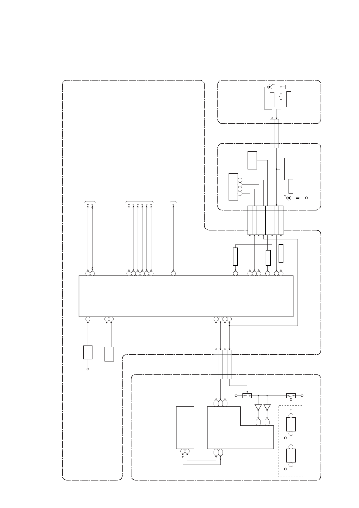
29
BLOCK DIAGRAMS
System Control Block Diagram
IC2000
IC6905 (EEPROM)
IC6001
(SUB MICRO CONTROLLER)
(MAIN MICRO CONTROLLER)
4
CN2001
15 15KEY-1
14 14REMOTE
13 13FL-RESET
12 12FL-CS
11 11FL-SCL
10 10FL-SDA
XRST
XTRST
CN7001 CN2000
15 15SUB-TXD
14 14SYS-RESET
13 13RDY
16 16SUB-RXD
BE MAIN CBA UNIT AV CBA
27
20
34
33
44
43
M3
14
8
9
RESET
29
PWSW237PWSW3
40
48 SUB-TXD
49
L3
A16
SUB-RXD
IIC-BUS SCL
39IIC-BUS SDA
IIC-BUS SCL
IIC-BUS SDA
PWSW2
PWSW3
SYS-RESET
RDYRDY
B18
TXD1
G18
A18
A17
RXD1
SCL
SDA
SCL
SDA
FL-SDA
FL-SCL
FL-CS
REMOTE
KEY-1
OSC2
OSC1
8MHz
X'TAL
X2000
EV+3.3V
IC2001
RESET
D+3.3V
D+3.3V
Q6702
Q6703
Q6701
26
FL-SW
FL-SW
TO POWER SUPPLY
BLOCK DIAGRAM
TO VIDEO
BLOCK DIAGRAM
31AUDIO-MUTE
AUDIO-MUTE
45FAN-CONT
FAN-CONT
50V5V-PW-SW
V5V-PW-SW
24MAIN-P-ON
MAIN-P-ON
TO AUDIO
BLOCK DIAGRAM
Q6704
5
6
RESET
IC6702
1
D+3.3V
Either IC6701 or IC6702 is used for BE MAIN CBA UNIT.
D+3.3V
RESET
IC6701
2 1
3
19 20 21 22
CN3000
FL3000
VFD
FRONT CBA
RS3000
REMOTE
SENSOR
KEY SWITCH
Q2002
BUFFER
18 18
POWER-LED
60
LED DRIVEPOWER-LED
Q2003
SW3100
D3101
POWER
CN3100CN3001
1 1
POWER-KEY
2 2
POWER-LED
POWER
POWER SW CBA
59DISC-IN-LED
LED DRIVE
Q2004
D3010
DISC-IN
EV+5V
19 19
DISC-IN-LED
BLOCK DIAGRAMS
System Control Block Diagram
Page 32
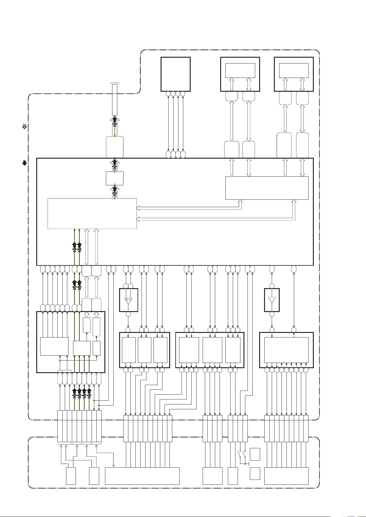
30
BD MECHANISM FE MAIN CBA
W 1
V 2
U 3
HU(+) 5
HU(-) 6
HV(+) 7
HV(-) 8
HW(+) 9
HW(-) 10
CN903
IC001 (MAIN MICRO CONTROLLER/FE DIGITAL SIGNAL PROCESS)
IC902 (MOTOR DRIVE) IC301 (OP AMP)
TRACKING
ACTUATOR
DRIVE
OEIC
(CD/DVD)
IC903 (MOTOR DRIVE)
IC904
IC301 (OP AMP)
(MOTOR DRIVE)
16MBIT
NOR
FLASH
ROMDQ(0-15)
ROMA(1-20)
A(0-11)
DQ(0-15)
IC402 (NOR FLASH)
IC002 (RF AMP)
TO DIGITAL
SIGNAL PROCESS 2
BLOCK DIAGRAM
(CN6401)
CN501
3-18
AG22-AG24,
AH20-AH24,
AJ20-AJ22,
AK20-AK24
21,22,24,
25,27,29
AH12-AH18,
AG15-AG19
2-13,
42-53
1-9,
16-25,48
29-36,
38-45
22-26,
29-35
AJ11-AJ15,
AJ18,AJ19,
AK10-AK13,
AK15-AK19
N27,N28,N30,
P27-P30,R27-R30,
T27-T30,U27,U29,
U30,V27,W27
H28-H30,J28-J30,
K27-K30,L27,L28,
L30,M27,M28,M30
IDE1D(0-15)
37,38,40,
42,45,47
A5-A7,
B5-B7
C5-C7,
D5-D7
64MBIT
SDRAM
IC401 (SDRAM)
IC403 (EEPROM)
ATA P I
I/F
MEMORY
I/F
FE
DIGITAL
SIGNAL
PROCESS
MATRIX
RF EQ
AG28
AH4
AG5
U4
U3
T2R3T1
R4
AA1
Y3
K4100
125-128
AH29
AH28
AH30
247
9
1011121314
SLD2(+) 4
SLD2(-) 3
SLD1(+) 2
SLD1(-) 1
CN902
LOAD(+) 5
LOAD(-) 6
LDSNS1 2
LDSNS2 1
CN901
TD 3
TR 4
FD1 1
FR1 2
EXPA(+) 9
EXPA(-) 7
EXPB(+) 10
EXPB(-) 8
A-D 21-24
E-H 26-29
OEVC 25
RF(+) 17
RF(-) 18
BDRF(+) 14
BDRF(-) 15
S D A TA 40
SCLK
S D A TA
SCLK
S D A TA
SCLK
38
CN101
CN101
151617
18
141312
11
141315
16
LOADING
MOTOR DRIVE
10
9
COLLIMATE
LENS
MOTOR DRIVE
SLED
MOTOR DRIVE
SPINDLE
MOTOR
DRIVE
FOCUS 1
ACTUATOR
DRIVE
TRKCTL-2
ADR(0-5)
ADW(0-5)
SWRF
TRKCTL-1
PCS1-B
PCS1-A
PCS2-B
PCS2-A
SLED1-CONTROL
SLED2-CONTROL
LOAD1-CONTROL
LDSNS1
LDSNS2
SPINDLE-CONTROL
SPINDLE-FG
LOAD2-CONTROL
LOAD-CONTROL
EXPA-CONTROL
EXPB-CONTROL
5
26
17
18
FOCUS 2
ACTUATOR
DRIVE
23
24
5276
U2
U1
23
26
1
2
V4
AG10
AK5
3
V1
22 14 13
W1
19
115-118
120
141
140
143
142
75
74
J2
K2
102
103
SE
PI
K1
J3
104
105
TE
CE
H3106
FE
C2
C1
8
9
RF ADC
WOB ADCWOB FE
1
3
2
T4
T3
OEIC
(BD)
LASER
DIODE
DRIVE
SLED
MOTO R
TRAY
-OUT
TRAY
-IN
SPINDLE
MOTO R
FD2 6
FR2 5
LOADING
MOTO R
VIDEO SIGNAL AUDIO SIGNAL
SCK
SI
SCK_0
SO_0
6
5
/CEE2CS 1
SOSI_0 2
Digital Signal Process 1 Block Diagram
Page 33
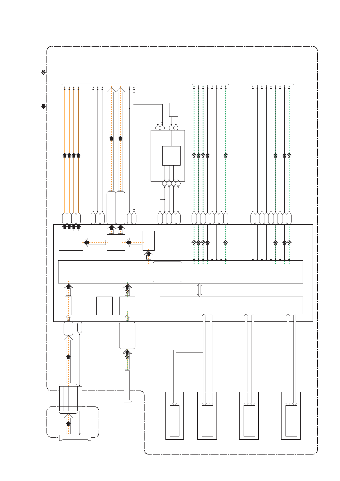
31
SD CBA BE MAIN CBA UNIT
STREAM
CONTROL
ATAPI I/F
ED (0-7)
ED (0-15) ED (0-15)
EA (1-22)
C0DQ (0-31)
PC0A (0-12)
C1DQ (0-31)
MEDIA
PROCESSOR
Java (BD-J)
MPEG-2
DECODER
HD (TS)
SD (PS)
COPY
PROTECT
AACS
/BD+
SD
CARD
SLOT
TO DIGITAL
SIGNAL PROCESS 1
BLOCK DIAGRAM
(CN501)
CN4001 CN7602
CN6401
CN4002
MEMORY
I/F
SD I/F
IC6001 (BE DIGITAL SIGNAL PROCESS)
IC6704 (CLOCK GENE.)
F25
A3
C14
C13
B14
IC6901
(NAND FLASH MEMORY)
NAND FLASH
MEMORY (64Mbit)
IC6902 (NOR FLASH MEMORY)
(DDR SDRAM)
NOR FLASH
MEMORY (8Mbit)
IC6501,IC6502,IC6503,IC6504
DDR SDRAM
(512Mbit x 4)
3-18 IDE1D(0-15)
13 13SDDAT0
15 15SDDAT1
1 1SDDAT2
3 3SDDAT3
11 11SDCLK
(DDR SDRAM)
IC6507,IC6508,IC6509,IC6510
DDR SDRAM
(512Mbit x 4)
D33,D34,E32-E34,
F32-F34,G30,G32,
H29,H30,H32,
J28-J30
A8,A9,A11,B8,B10,B11,
C11,E12,E13,F14,G13,G14
A10,A12,A13,B9,B12,B13,
C10,C12,E14,F13,F15,G15
A27,B27,
F26,G26
GRAPHICS
/OSD
PIXEL
DATA I/F
VIDEO
DAC
CLK
VS
HS
SD CLOCK
SD DATA(0-3)
TO VIDEO
BLOCK DIAGRAM
VIDEO
PRMCLK
PRMVS
PRMHS
PRMC(0-11)
PRMY(0-11)
SCL
33M CLOCK
33M CLOCK
74M CLOCK
27M CLOCK
768K CLOCK
SCL
SDA
HDMI-DATA0
HDMI-DATA1
HDMI-DATA2
HDMI-DATA3
HDMI-MCK
HDMI-BCK
HDMI-LRCK
HDMI-SPDIF
X6701
27MHz
OSC
CLOCK
GENE.
SDA
VIDEO-Y(I/P)
VIDEO-Pb/Cb
VIDEO-Pr/Cr
VIDEO SIGNAL AUDIO SIGNAL
E9
C5
G9
SCL
B16
SDA
C16
TO VIDEO
BLOCK DIAGRAM
E11
AP2
F11
D10
A6
C7
G11
B6
A5
2
3
1
16
789
10
F28
A31
B30
A28
MC
MD
SCK
BCK
LRCK
D AT A 0
MS1
D AT A
SPDIF
TO AUDIO
BLOCK DIAGRAM
G19
G20
L1
K5
K3
L6
M34
K2
M7
Digital Signal Process 2 Block Diagram
Page 34

32
AV CBABE MAIN CBA UNIT
1 1VIDEO-Y(I/P)
3 3VIDEO-Pb/Cb
9 9VIDEO
5 5VIDEO-Pr/Cr
HDMI-DATA0
HDMI-DATA1
HDMI-DATA2
HDMI-DATA3
HDMI-MCK
HDMI-BCK
HDMI-LRCK
HDMI-SPDIF
70-73,75-78,
92,94,102,103
50,51,53-57,59,
87,88,90,91
TO DIGITAL
SIGNAL
PROCESS 2
BLOCK DIAGRAM
TO DIGITAL
SIGNAL
PROCESS 2
BLOCK DIAGRAM
IC2300 (VIDEO DRIVER)
DC
SHIFT
6dB
AMP
LPF DRIVER
17
DC
SHIFT
6dB
AMP
LPF DRIVER
3
15
DC
SHIFT
IIC
I/F
IIC-BUS SCL
VIDEO
SCL
SDA
PRMCLK
PRMVS
PRMHS
PRMC(0-11)
PRMY(0-11)
VIDEO-Y(I/P)
VIDEO-Pb/Cb
VIDEO-Pr/Cr
TO SYSTEM CONTROL
BLOCK DIAGRAM
IIC-BUS SDA
6dB
AMP
LPF DRIVER
5
VIDEO-Pb/Cb
OUT
VIDEO-Y
OUT
VIDEO-Pr/Cr
OUT
JK2300
C2314
1 20
T.M.D.S DATA2-
T.M.D.S DATA2+
T.M.D.S DATA1-
T.M.D.S DATA1+
T.M.D.S DATA0-
T.M.D.S DATA0+
T.M.D.S CLOCK+
T.M.D.S CLOCK-
JK7501
HDMI-CONNECTOR
DDC DAT A
DDC CLOCK
HOT PLUG
DETECT
IC7501 (HDMI INTERFACE)
649
7
10
12
3
1
151916
REGISTER
IIC
I/F
VIDEO
I/F
DDC
I/F
AU THENT
/CATION
KEY
EXCHANGE
IC7502
Q7505,Q7506
3.3V<-->5V
CONVERTER
AUDIO
I/F
HDCP
CIPHER/
ENCRYPTOR
TMDS
ENCODER
AV
CONTROLLER
TMDS
SERIALIZER
6
5
2
3
46454442413936
35
DRIVE
23251921151713
11
113
116
118
120
119
VIDEO SIGNAL AUDIO SIGNAL
CLK
CN2000CN7001
VS
HS
121
83
84
IC2301 (VIDEO DRIVER)
4dB
AMP
LPF 5
8dB
AMP
DRIVER
3
VIDEO OUT
(COMPOSITE)
9
10
WF1 WF2
WF3
Video Block Diagram
Page 35

33
AV CBABE MAIN CBA UNIT
AUDIO SIGNAL
IC7000
(AUDIO D/A CONVERTER)
AUDIO
DAC
345
827
6
(L-CH)
(R-CH)
1
R-CH
MUTE
L-CH
MUTE
16
14
15
AUDIO(L)-
OUT
AUDIO(R)-
OUT
Q2203
MUTE-ON
Q2202
MUTE-ON
Q2200
DRIVE
Q2201
DRIVE
JK2200
IC2200
(OP AMP)
7
1
6
2
27 27AUDIO(L)
25 25AUDIO(R)
28 28AUDIO(L)-MUTE
23 23AUDIO(R)-MUTE
22 22SPDIF
CN7001 CN2000
DIGITAL
AUDIO OUT
(COAXIAL)
TO SYSTEM CONTROL
BLOCK DIAGRAM
AUDIO-MUTE
TO DIGITAL
SIGNAL
PROCESS 2
BLOCK DIAGRAM
MCMDSCK
BCK
LRCK
MS1
D AT A
SPDIF
JK2100
Q2100
WF4
WF5
BUFFER
Audio Block Diagram
Page 36
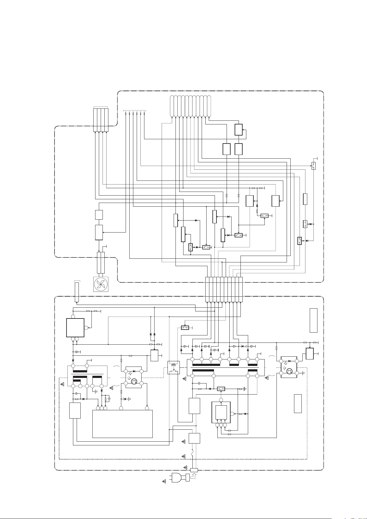
34
Power Supply Block Diagram
CAUTION !
Fixed voltage (or Auto voltage selectable) power supply circuit is used in this unit.
If Main Fuse (F1001) is blown , check to see that all components in the power supply
circuit are not defective before you connect the AC plug to the AC power supply.
Otherwise it may cause some components in the power supply circuit to fail.
NOTE:
The voltage for parts in hot circuit is measured using
hot GND as a common terminal.
CAUTION !
For continued protection against fire hazard,
replace only with the same type fuse.
IC1001
(
SWITCHING CONTROL
)
HOT
COLD
Q2600
Q2604
Q2606
Q2603
Q2607
Q2602
Q2601
D1009
Q2605
Q1003
VDD
POWER SUPPLY CBA
2
4
7
6
T1001
RL1001
Q1012
11
12
15
13
10
9
16
14
AC1002
F1001
LINE
FILTER
FEEDBACK
VDD
CURR. LIMIT
VCC
OUTPUT
L1006
3
4
IC1003
ERROR
VOLTAGE DET
1
2
P-ON+12V(1)
SHUNT
REG.
IC2601
IC2600
IC1005
D1001 - D1004
BRIDGE
RECTIFIER
D1041 - D1044
BRIDGE
RECTIFIER
DC-DC
CONVERTER
SWITCHING
CONTROL
5
2
3-5 AL+5V
1 AL+2.5V
6 AL+3.3V
20 F1
22 F2
23 FL
2 AL+12V(1)
15-17
3-5
1
18 EV+5V 18
6
202223
2
15-17
21 21
MAIN-P-ON
AL+12V(2)
CN1001 CN2600
CN1002
FAN-VCC 1
2GND
CN2004
SW+12V
AUDIO+3.3V
1-3 P-ON+10.5V
7,8 P-ON+5V(1)
CN2601
11 P-ON+1.2V
14,15
P-ON+3.3V
P-ON+3.3VF1F2
FL
TO SYSTEM
CONTROL
BLOCK
DIAGRAM
PWSW3
PWSW2
FL-SW
P-ON+5V(2)
AL+3.3V
EV+5V
AUDIO+5V
VIDEO+5V
SW+10.5V
SW+5V
SW+5V
+3.3V
REG.
Q2280
+5V
REG.
Q2302
+5V
REG.
SW
+5V
+1.2V
REG.
Q2101
FL REG.
6
1
3
HOT CIRCUIT. BE CAREFUL.
FAN
AV CBA
Q2014
Q2012
Q2013
V5V-PW-SW
FAN-CONT
FAN
CONTROL
Q2000,Q2001
+12V
REG.
Q2005
AC CORD
1
235
6
T1002
9
543
1
2
2 873
8
3
4
IC1002
ERROR
VOLTAGE DET
1
2
D1031
SHUNT
REG.
2.5A L 250V
IC1004
(BATTERY CHARGER IPD)
MAIN-P-ON
TO FE MAIN
CBA
(CN001)
TO BE MAIN
CBA UNIT
(CN7401)
Q2300,Q2301
2-5 AL+5V
Power Supply Block Diagram
Page 37
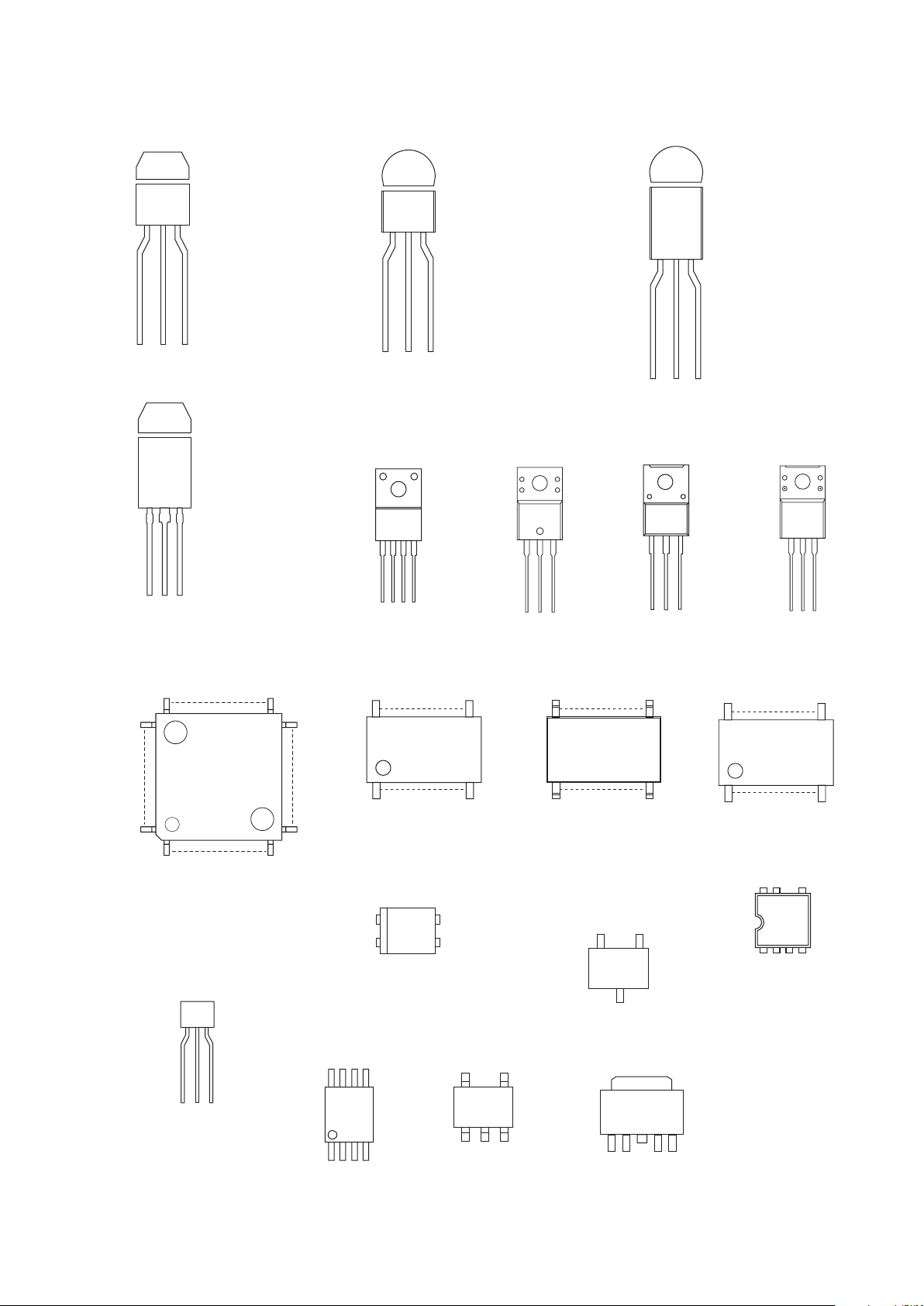
35
LEAD IDENTIFICATIONS
20
11
10
1
1234
48
17
32
33
16
1
64
49
123
54
1 4
8 5
1
2
4
3
1: Anode
2: Cathode
3: Emitter
4: Collector
8
5
4
1
C
BE
58
4
1
ECB
12 45
3
ECB
1 2 3
1: GND
2: OUT
3: IN
ECB
ECB
GDS
BCE
5
87
1234
ECB
Note:
A: Anode
K: Cathode
E: Emitter
C: Collector
B: Base
R: Reference
G: Gate
D: Drain
S: Source
BH7602FS-E2
2SA1980M Y
2SC5343M Y
2SC5343MG-AT
2SC5343Y-AT
KRA105M-AT/P
KRC102M-AT/P
KRC103M-AT/P
KTA1267-Y-AT/P
KTC3199-(GR,Y)-AT/P
SRA2205M
SRC1203MAT
PQ070XF02SZH
STC403
KTA1273-Y-AT/P
KTC3205-Y-AT/P
STD1862LY-AT
KTC2026-Y/P
2SK3798(Q)
2SK3798(Q.M)
PST3630NR
PST8430NR
EL817B
LTV-817B-F
PS2561A-1(Q,W)
AZ4580MTR-E1
FA5541N-A2-TE1
S4580
TB7102F
MM1636XWRE
2SA1530A-T112-1Z
2SA1980SFY
KRC101S-RTK/P
KTA1504S-Y-RTK/P
SRC1201SF
UTC4580EMN101C77AFS3
PQ035ZN01ZPH
2SA1981Y-AT
2SC1815-(GR,Y)(TE2 F T)
2SC5344 Y
KTA1266-Y-AT/P
KTA1271-Y-AT/P
KTC3198-Y-AT/P
KTC3203-Y-AT/P
2SD2144S
STB1277LY-AT
MIP2F10MS
LEAD IDENTIFICATIONS
Page 38
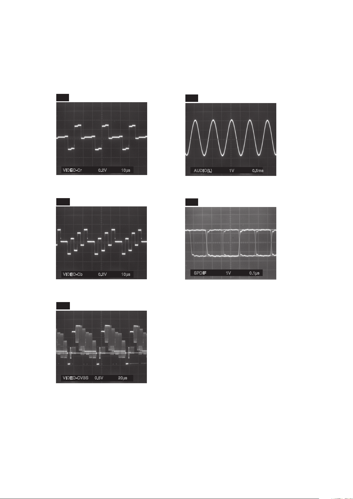
36
WF4
WF1
WF2
WF3
Pin 27 of CN2000
Pin 5 of CN2000
WF5
Pin 22 of CN2000
Pin 3 of CN2000
C2314 PLUS LEAD
20µs0.5VVIDEO-CVBS
VIDEO-Cr 0.2V 10µs
VIDEO-Cb 0.2V 10µs
AUDIO(L) 1V 0.5ms
SPDIF 1V 0.1µs
NOTE:
Input Signal (DVD)
VIDEO: 75% COLOR BAR
AUDIO: 1kHz, 0dB
WAVEFORMS
Page 39

37
SCHEMATIC DIAGRAMS / CBA AND TEST POINTS
Standard Notes
WARNING
Many electrical and mechanical parts in this chassis
have special characteristics. These characteristics
often pass unnoticed and the protection afforded by
them cannot necessarily be obtained by using
replacement components rated for higher voltage,
wattage, etc. Replacement parts that have these
special safety characteristics are identified in this
manual and its supplements; electrical components
having such features are identified by the mark “!” in
the schematic diagram and the parts list. Before
replacing any of these components, read the parts list
in this manual carefully. The use of substitute
replacement parts that do not have the same safety
characteristics as specified in the parts list may create
shock, fire, or other hazards.
Notes:
1. Do not use the part number shown on these
drawings for ordering. The correct part number is
shown in the parts list, and may be slightly
different or amended since these drawings were
prepared.
2. All resistance values are indicated in ohms
(K = 10
3
, M = 106).
3. Resistor wattages are 1/4W or 1/6W unless
otherwise specified.
4. All capacitance values are indicated in µF
(P = 10
-6
µF).
5. All voltages are DC voltages unless otherwise
specified.
6. Electrical parts such as capacitors, connectors,
diodes, IC’s, transistors, resistors, switches, and
fuses are identified by four digits. The first two
digits are not shown for each component. In each
block of the diagram, there is a note such as
shown below to indicate these abbreviated two
digits.
SCHEMATIC DIAGRAMS AND TEST POINTS
Page 40

LIST OF CAUTION, NOTES, AND SYMBOLS USED IN THE SCHEMATIC DIAGRAMS ON
THE FOLLOWING PAGES:
1. CAUTION:
FOR CONTINUED PROTECTION AGAINST FIRE HAZARD, REPLACE ONLY WITH THE SAME TYPE
FUSE.
2. CAUTION:
Fixed Voltage (or Auto voltage selectable) power supply circuit is used in this unit.
If Main Fuse (F1001) is blown, first check to see that all components in the power supply circuit are not
defective before you connect the AC plug to the AC power supply. Otherwise it may cause some components
in the power supply circuit to fail.
3. Note:
1. Do not use the part number shown on the drawings for ordering. The correct part number is shown in the
parts list, and may be slightly different or amended since the drawings were prepared.
2. To maintain original function and reliability of repaired units, use only original replacement parts which are
listed with their part numbers in the parts list section of the service manual.
4. Voltage indications for PLAY and STOP mode on the schematics are as shown below:
5. How to read converged lines
6. Test Point Information
2
3
1
5.0
(2.5)
5.0
The same voltage for
both PLAY & STOP modes
Indicates that the voltage
is not consistent here.
PLAY mode
STOP mode
(Unit: Volt)
3
2
1
ABCD
1-B1
1-D3
AREA D3
AREA B1
1-D3
Distinction Area
Line Number
(1 to 3 digits)
Examples:
1. "1-D3" means that line number "1" goes to the line number
"1" of the area "D3".
2. "1-B1" means that line number "1" goes to the line number
"1" of the area "B1".
: Indicates a test point with a jumper wire across a hole in the PCB.
: Used to indicate a test point with a component lead on foil side.
: Used to indicate a test point with no test pin.
: Used to indicate a test point with a test pin.
38
Page 41
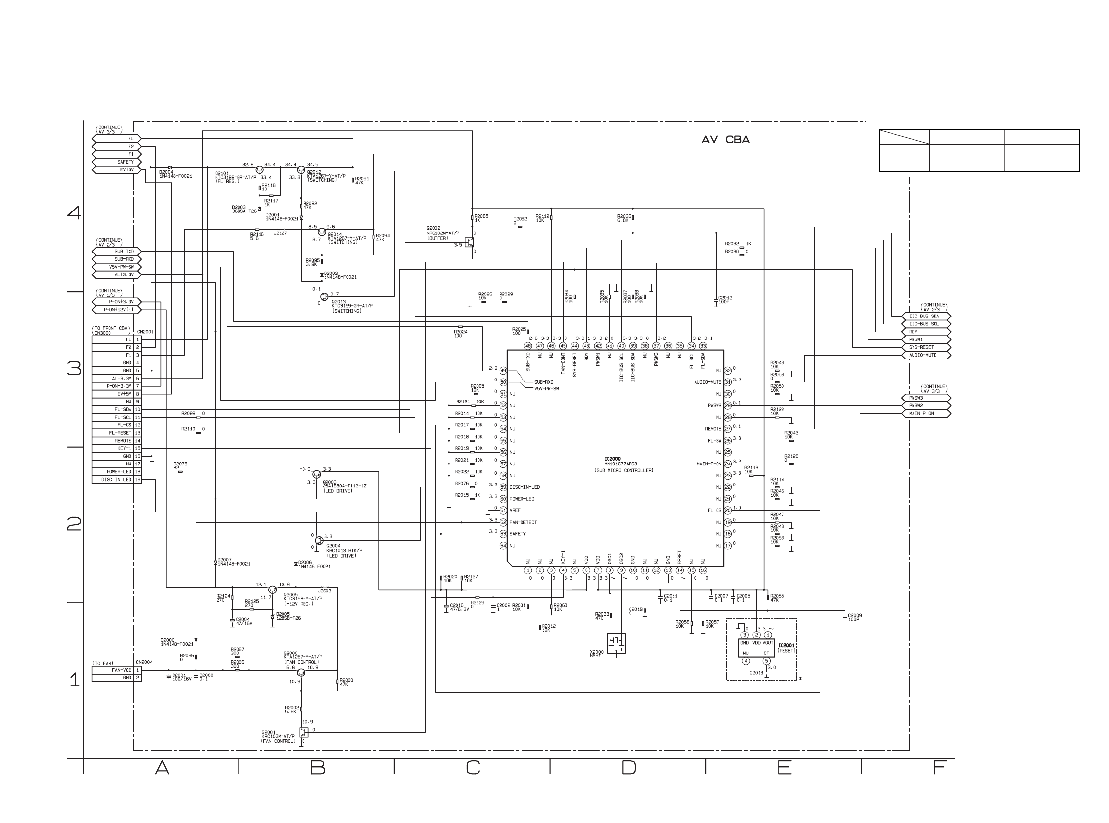
* NOTE
IC2001 PST3630NR PST8430NR
Group A Group B
C2013 0.1 0.01
These components (IC2001, C2013)
can be used in any models.
However, you cannot mix components under
Group A with the ones under Group B.
You can choose either Group. The difference
between Group A and Group B is shown below.
AV 1/3 Schematic Diagram
39 40
Page 42
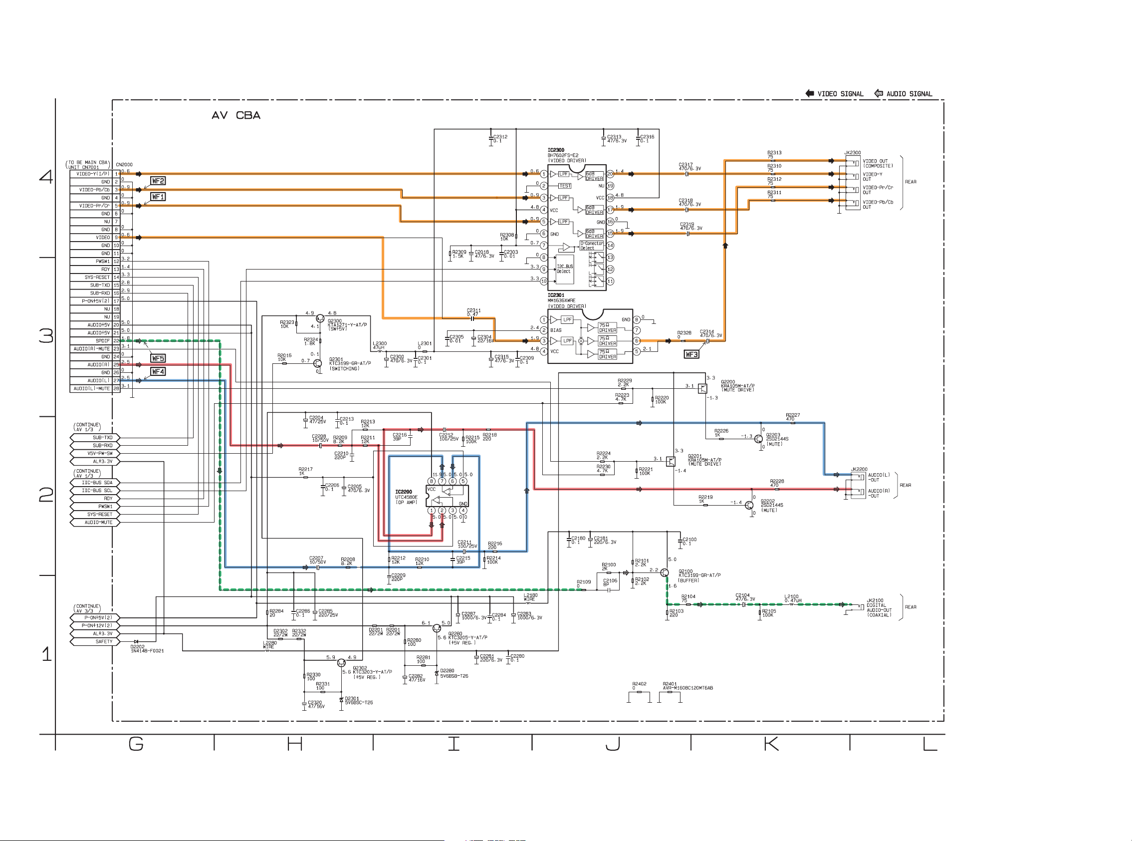
AV 2/3 Schematic Diagram
4241
Page 43
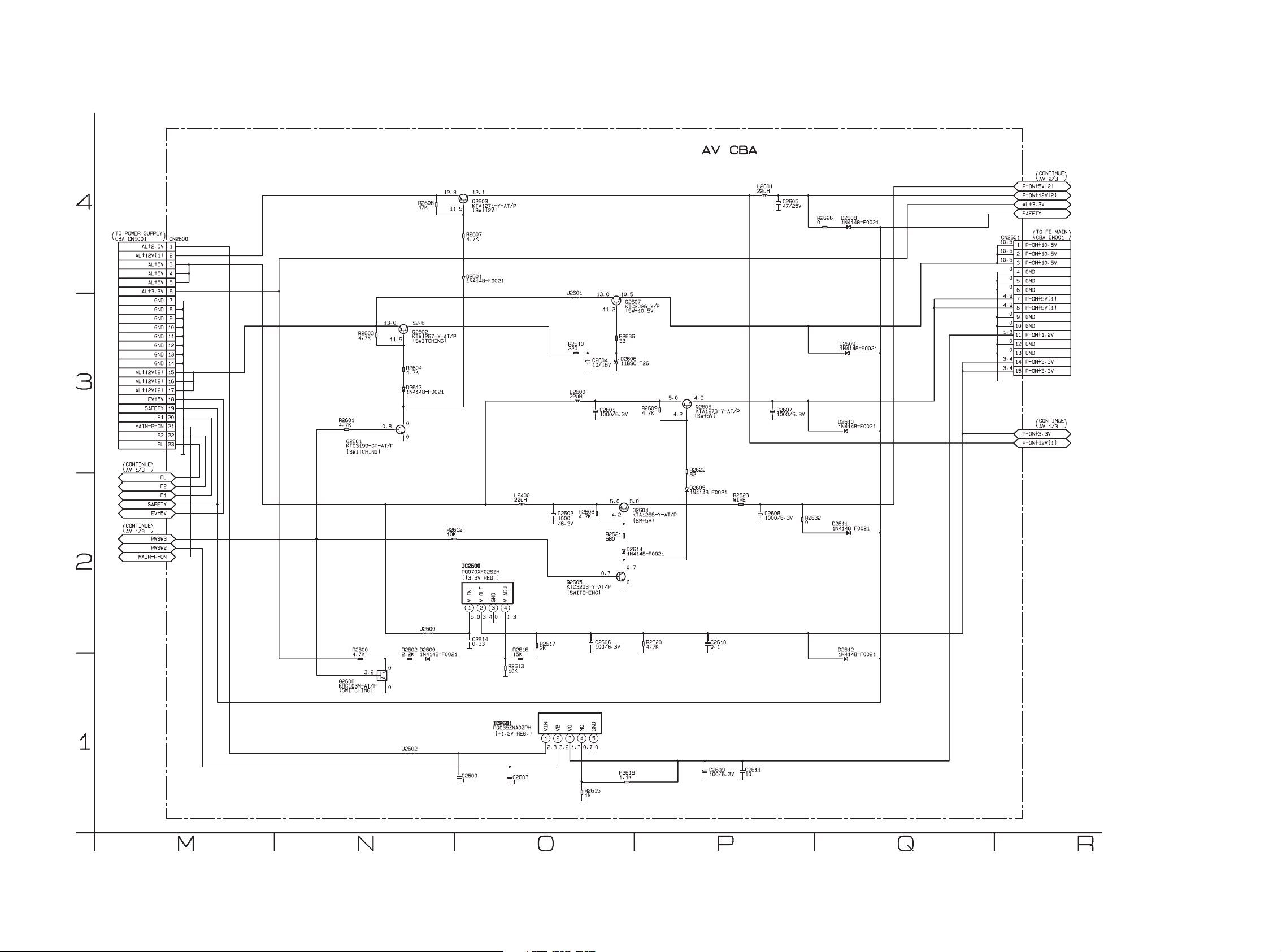
AV 3/3 Schematic Diagram
43 44
Page 44
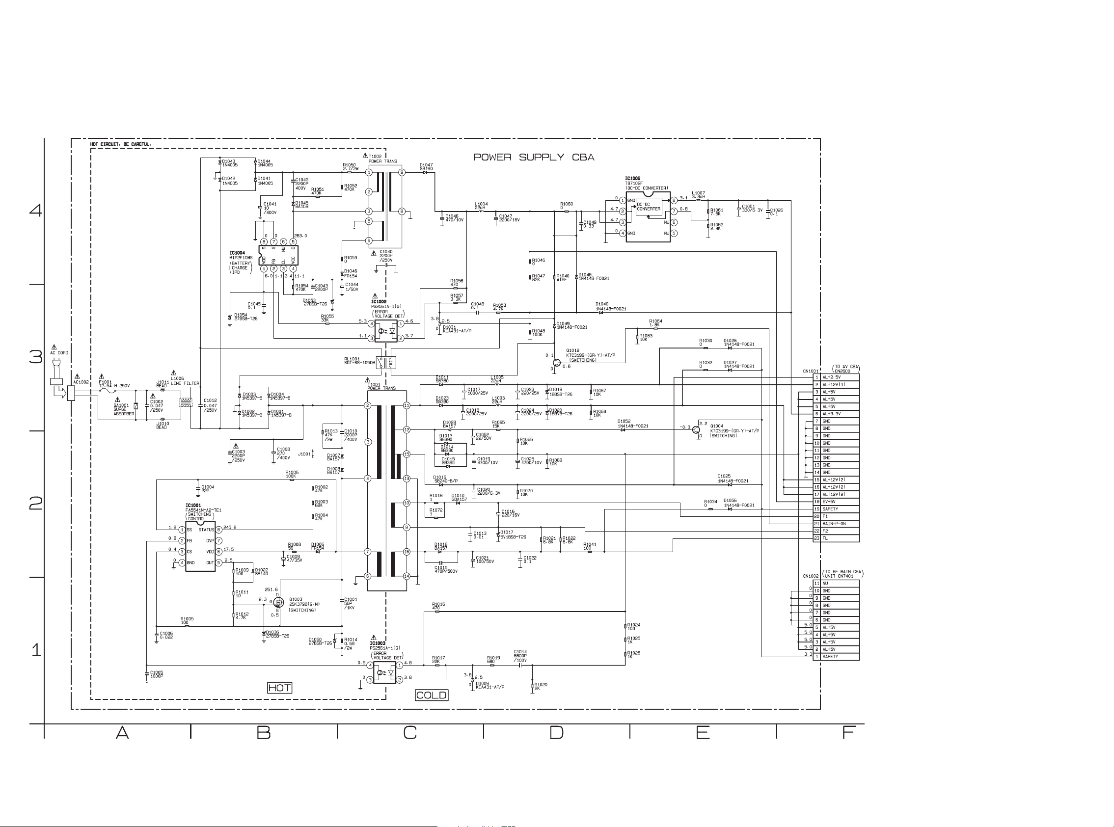
CAUTION !
Fixed voltage (or Auto voltage selectable) power supply circuit is used in this unit.
If Main Fuse (F1001) is blown , check to see that all components in the power supply
circuit are not defective before you connect the AC plug to the AC power supply.
Otherwise it may cause some components in the power supply circuit to fail.
CAUTION !
For continued protection against fire hazard,
replace only with the same type fuse.
NOTE:
The voltage for parts in hot circuit is measured using
hot GND as a common terminal.
Power Supply Schematic Diagram
4645
Page 45
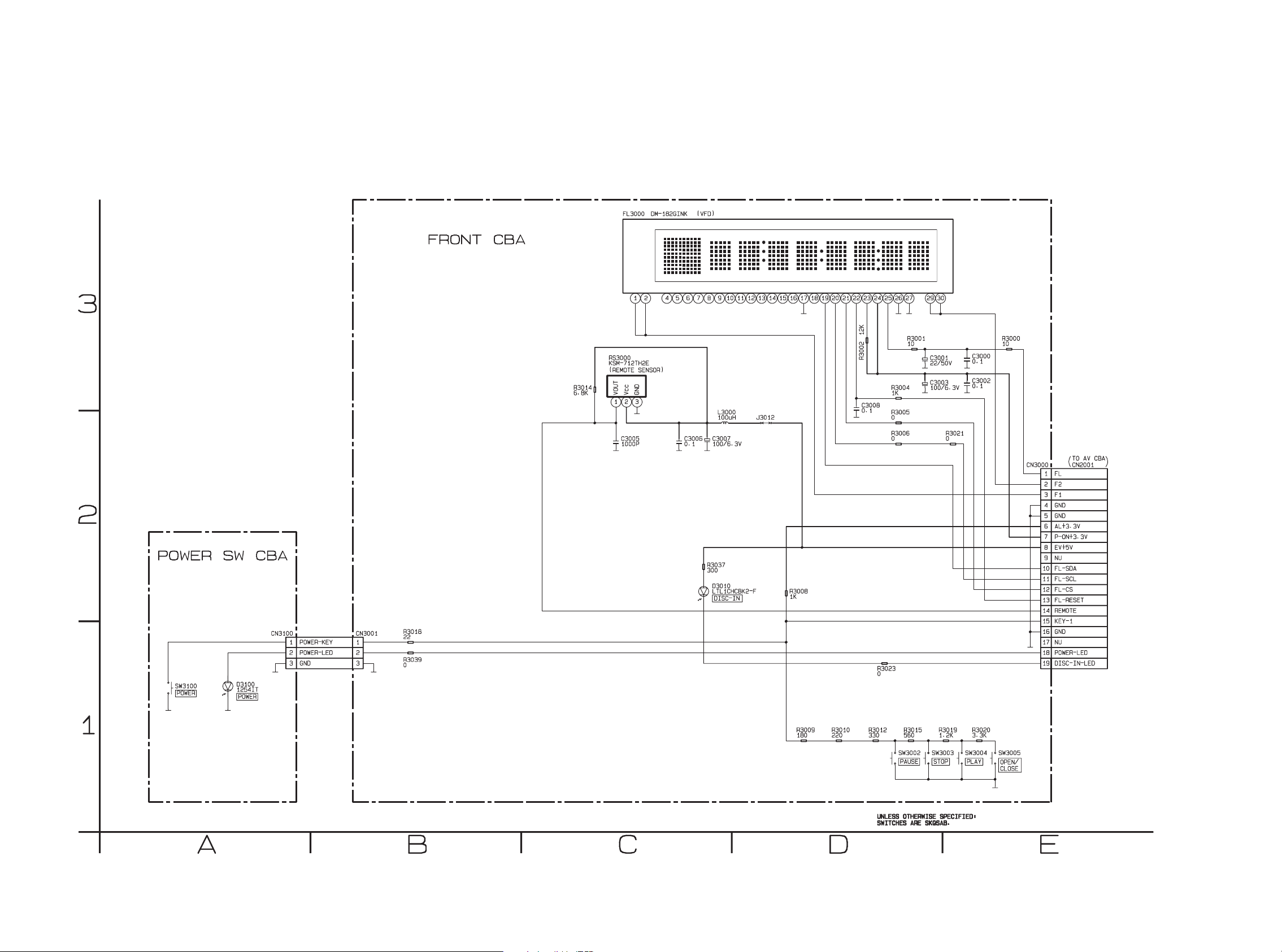
Front & Power SW Schematic Diagram
47 48
Page 46
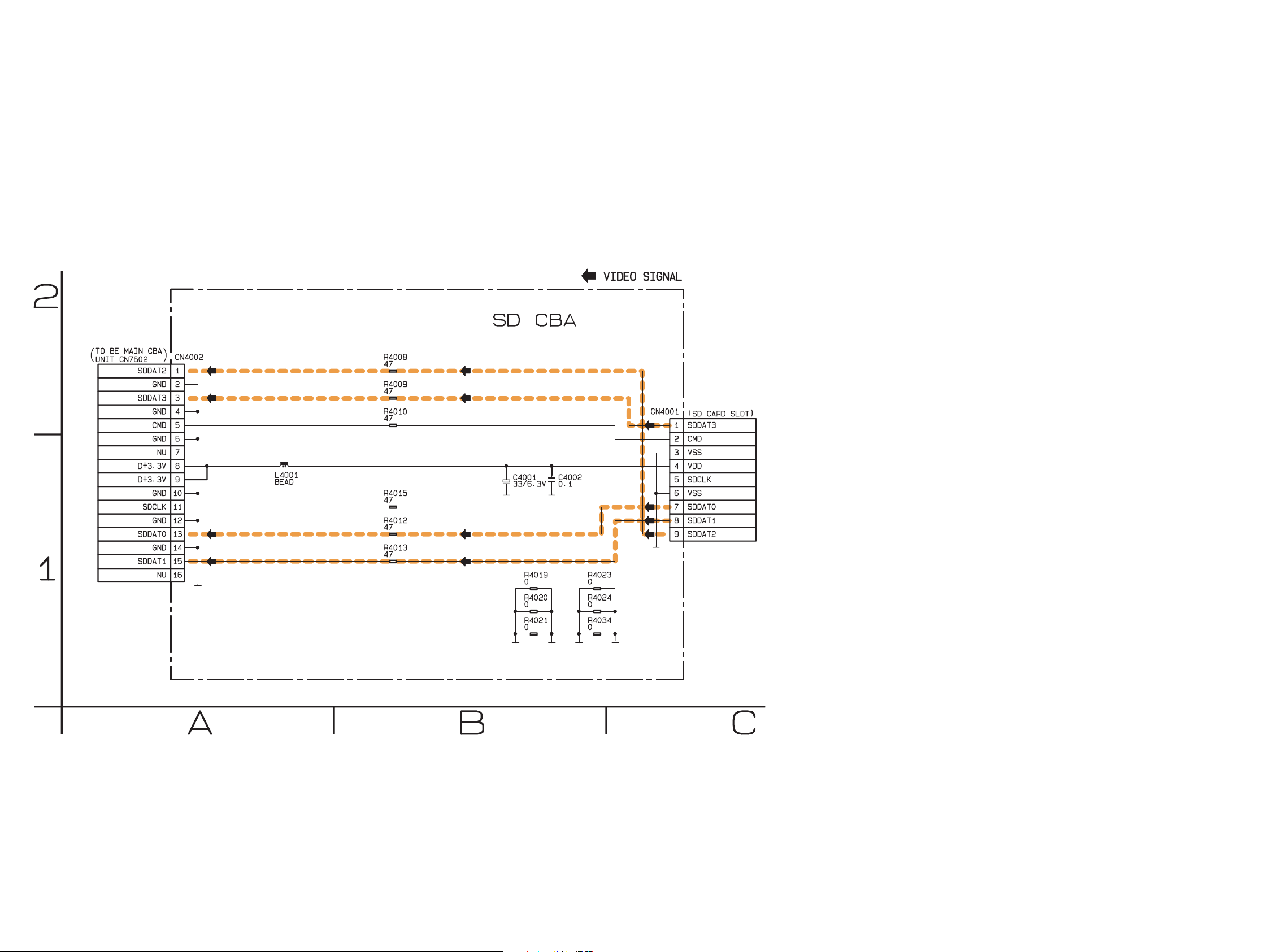
SD Schematic Diagram
5049
Page 47
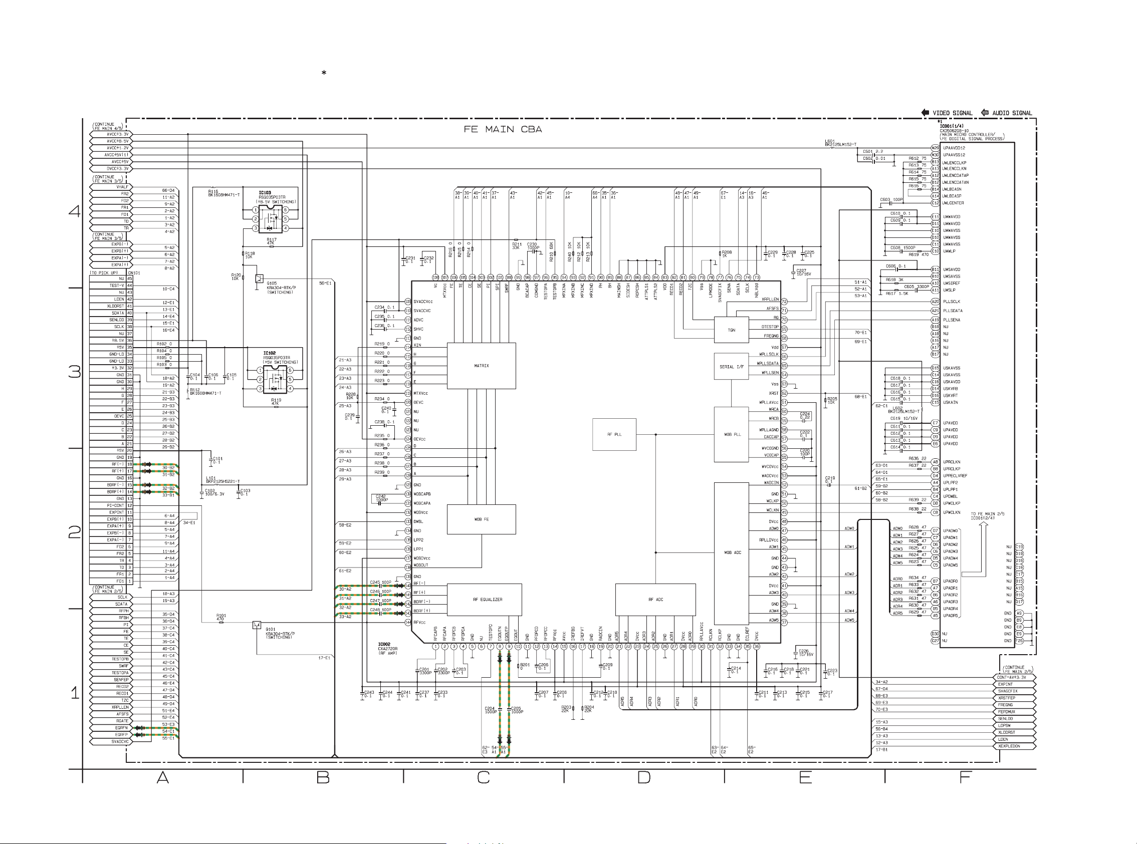
The order of pins shown in this diagram is different from that of actual IC001.
IC001 is divided into four and shown as IC001 (1/4) ~ IC001 (4/4) in this FE Main Schematic Diagram Section.
1 NOTE:
FE Main 1/5 Schematic Diagram
51 52
Page 48

The order of pins shown in this diagram is different from that of actual IC001.
IC001 is divided into four and shown as IC001 (1/4) ~ IC001 (4/4) in this FE Main Schematic Diagram Section.
1 NOTE:
FE Main 2/5 Schematic Diagram
5453
Page 49
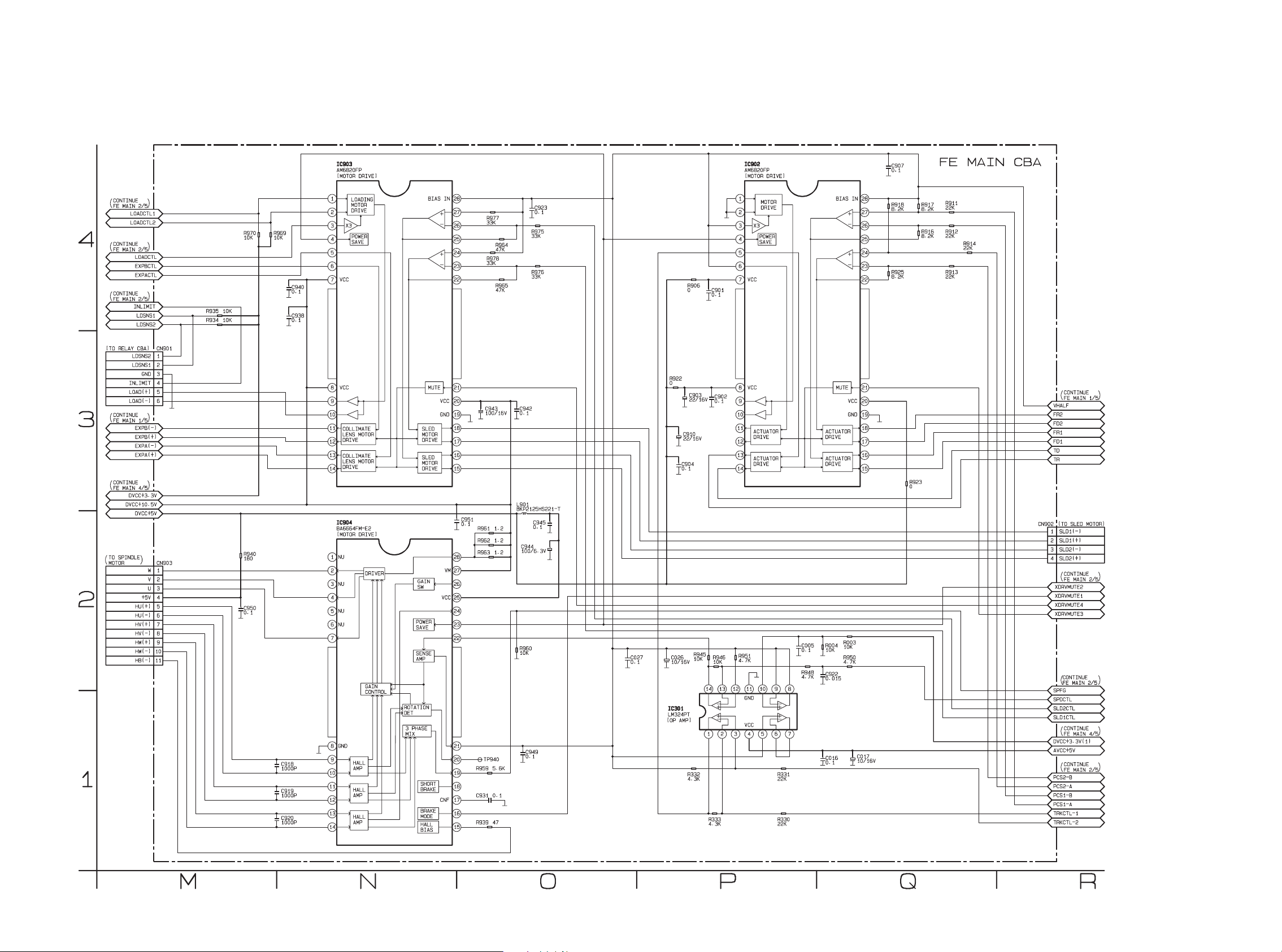
FE Main 3/5 Schematic Diagram
55 56
Page 50

The order of pins shown in this diagram is different from that of actual IC001.
IC001 is divided into four and shown as IC001 (1/4) ~ IC001 (4/4) in this FE Main Schematic Diagram Section.
1 NOTE:
FE Main 4/5 Schematic Diagram
5857
Page 51
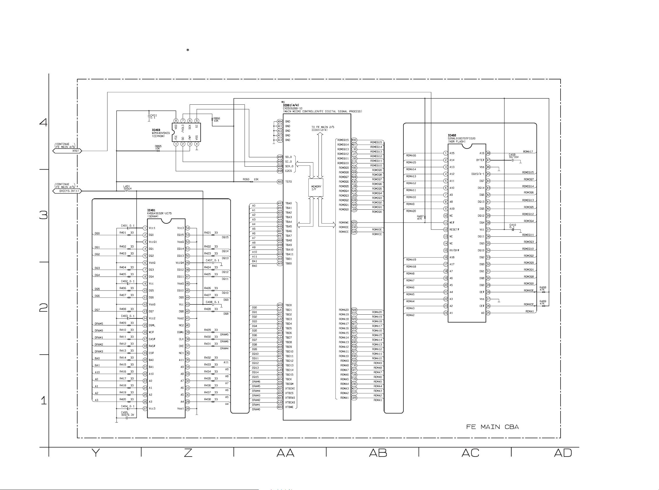
The order of pins shown in this diagram is different from that of actual IC001.
IC001 is divided into four and shown as IC001 (1/4) ~ IC001 (4/4) in this FE Main Schematic Diagram Section.
1 NOTE:
FE Main 5/5 Schematic Diagram
59 60
Page 52
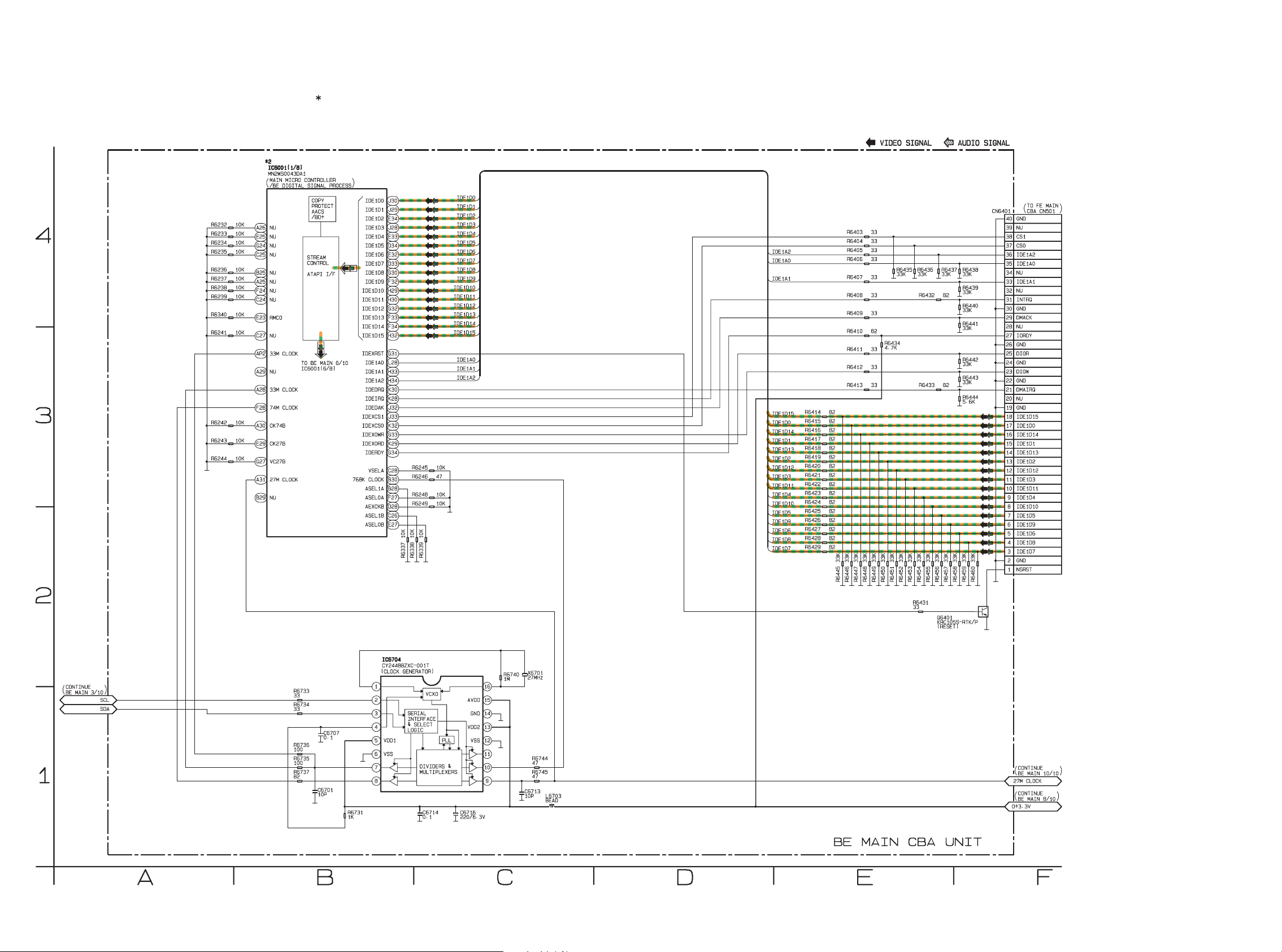
The order of pins shown in this diagram is different from that of actual IC6001.
IC6001 is divided into eight and shown as IC6001 (1/8) ~ IC6001 (8/8) in this BE Main Schematic Diagram Section.
2 NOTE:
BE Main 1/10 Schematic Diagram
6261
Page 53

The order of pins shown in this diagram is different from that of actual IC6001.
IC6001 is divided into eight and shown as IC6001 (1/8) ~ IC6001 (8/8) in this BE Main Schematic Diagram Section.
2 NOTE:
BE Main 2/10 Schematic Diagram
63 64
Page 54
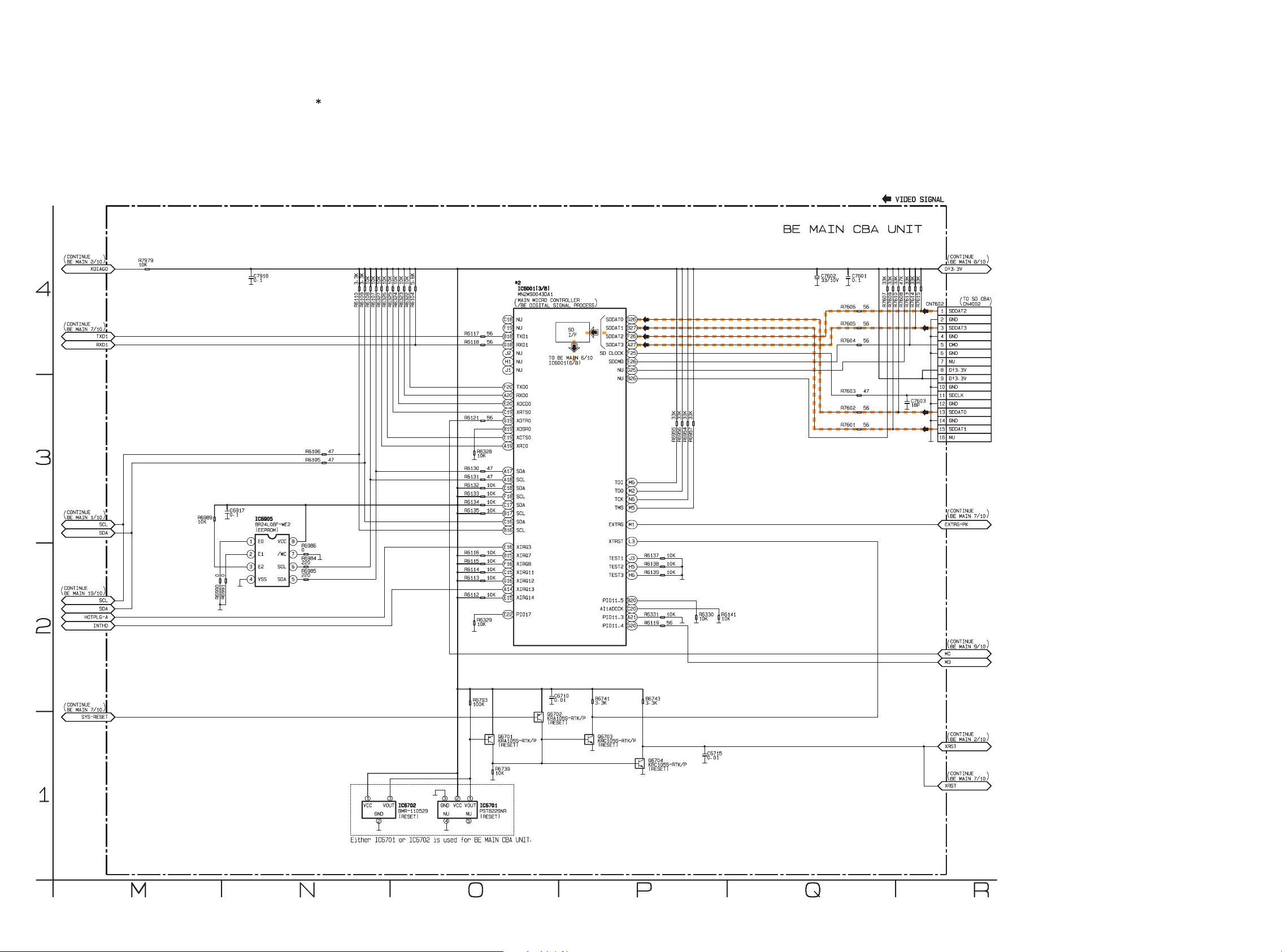
The order of pins shown in this diagram is different from that of actual IC6001.
IC6001 is divided into eight and shown as IC6001 (1/8) ~ IC6001 (8/8) in this BE Main Schematic Diagram Section.
2 NOTE:
BE Main 3/10 Schematic Diagram
6665
Page 55

The order of pins shown in this diagram is different from that of actual IC6001.
IC6001 is divided into eight and shown as IC6001 (1/8) ~ IC6001 (8/8) in this BE Main Schematic Diagram Section.
2 NOTE:
BE Main 4/10 Schematic Diagram
67 68
Page 56
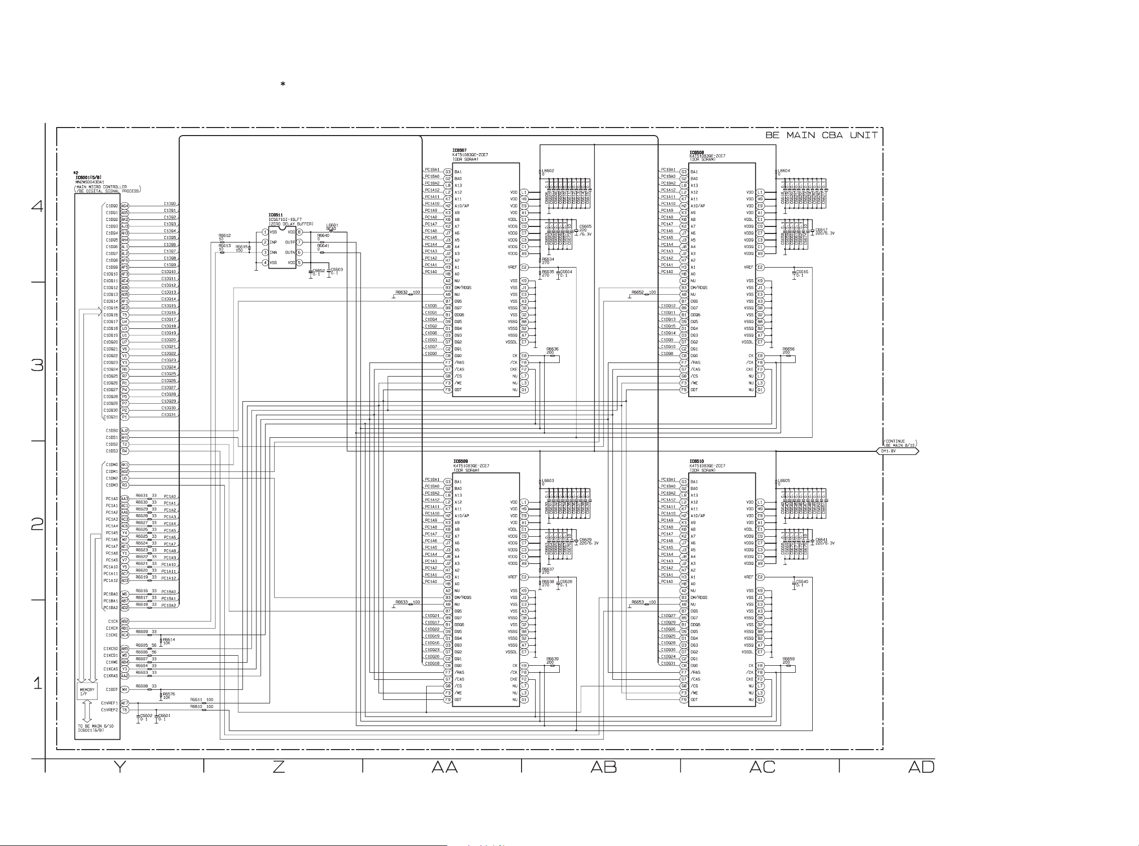
The order of pins shown in this diagram is different from that of actual IC6001.
IC6001 is divided into eight and shown as IC6001 (1/8) ~ IC6001 (8/8) in this BE Main Schematic Diagram Section.
2 NOTE:
BE Main 5/10 Schematic Diagram
7069
Page 57
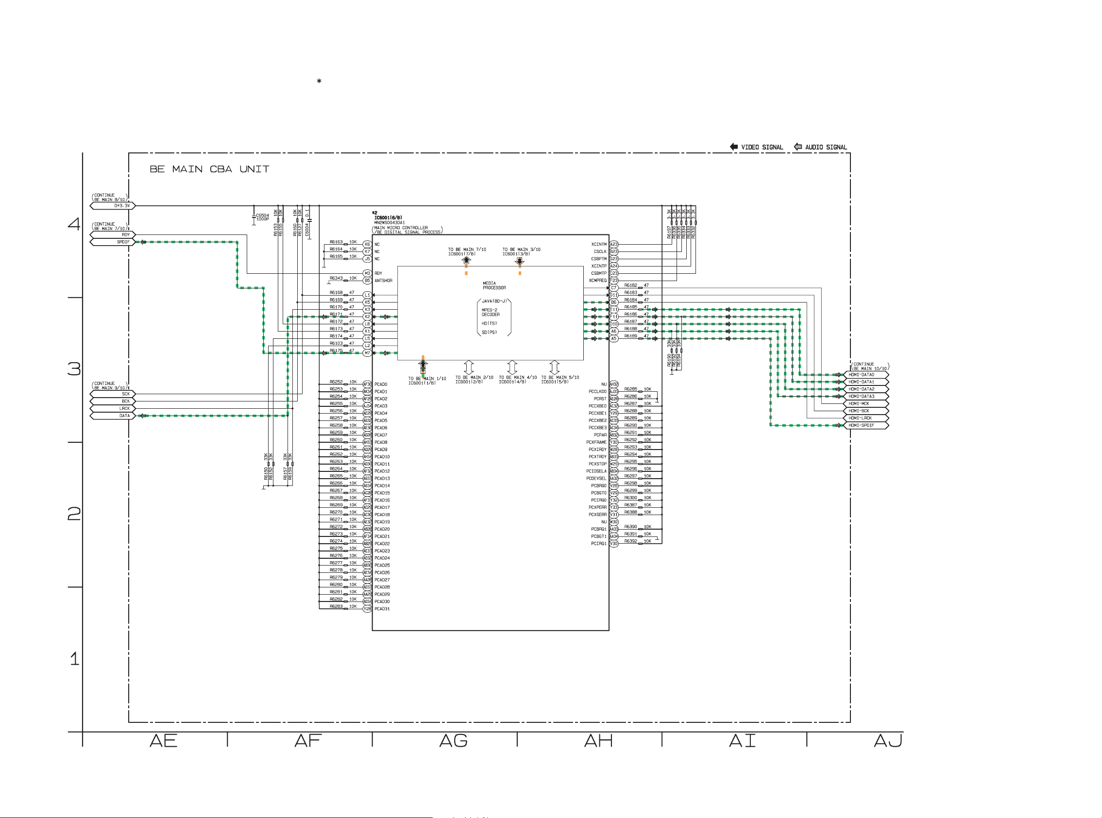
The order of pins shown in this diagram is different from that of actual IC6001.
IC6001 is divided into eight and shown as IC6001 (1/8) ~ IC6001 (8/8) in this BE Main Schematic Diagram Section.
2 NOTE:
BE Main 6/10 Schematic Diagram
71 72
Page 58
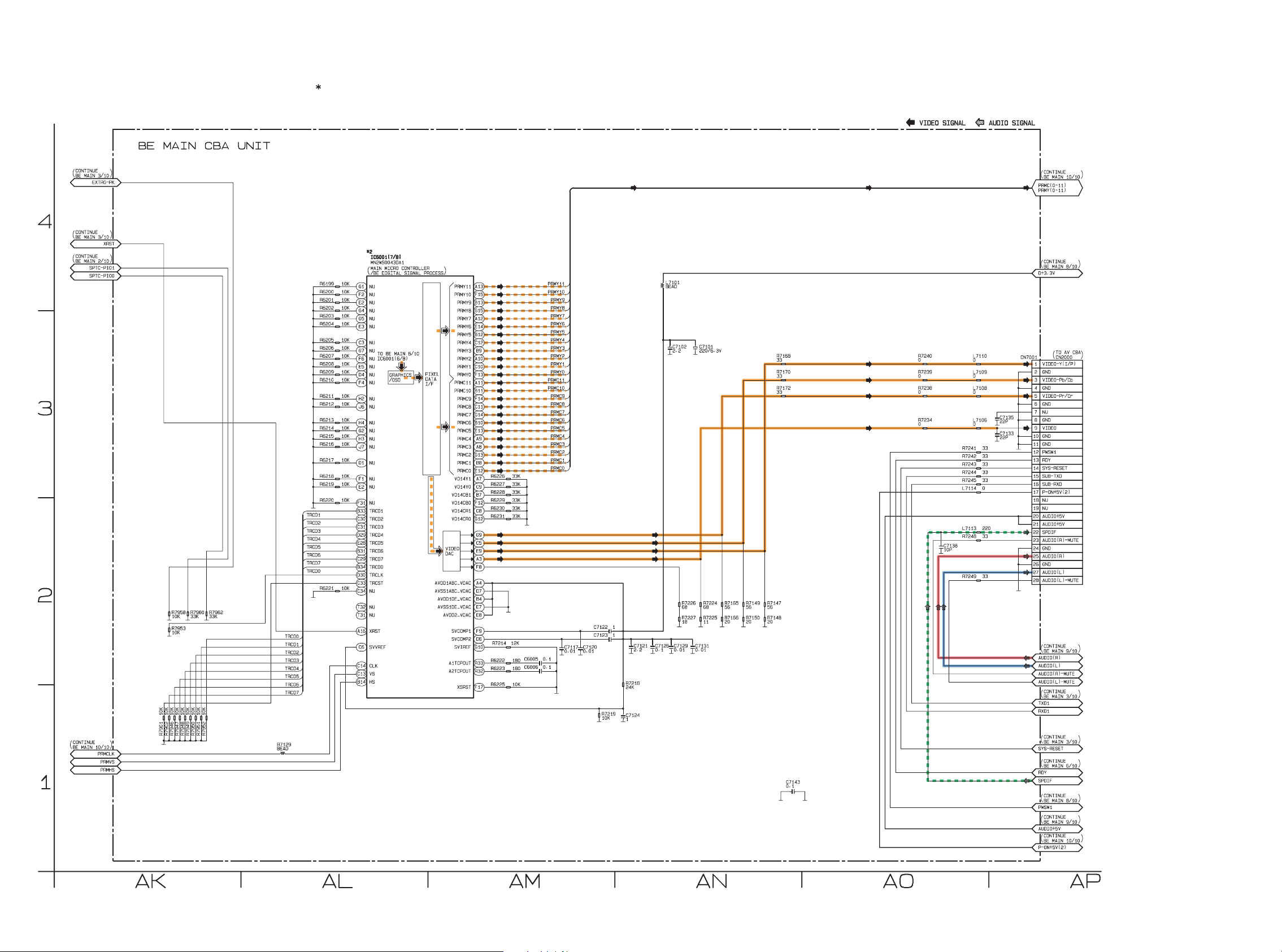
The order of pins shown in this diagram is different from that of actual IC6001.
IC6001 is divided into eight and shown as IC6001 (1/8) ~ IC6001 (8/8) in this BE Main Schematic Diagram Section.
2 NOTE:
BE Main 7/10 Schematic Diagram
7473
Page 59

The order of pins shown in this diagram is different from that of actual IC6001.
IC6001 is divided into eight and shown as IC6001 (1/8) ~ IC6001 (8/8) in this BE Main Schematic Diagram Section.
2 NOTE:
BE Main 8/10 Schematic Diagram
75 76
Page 60
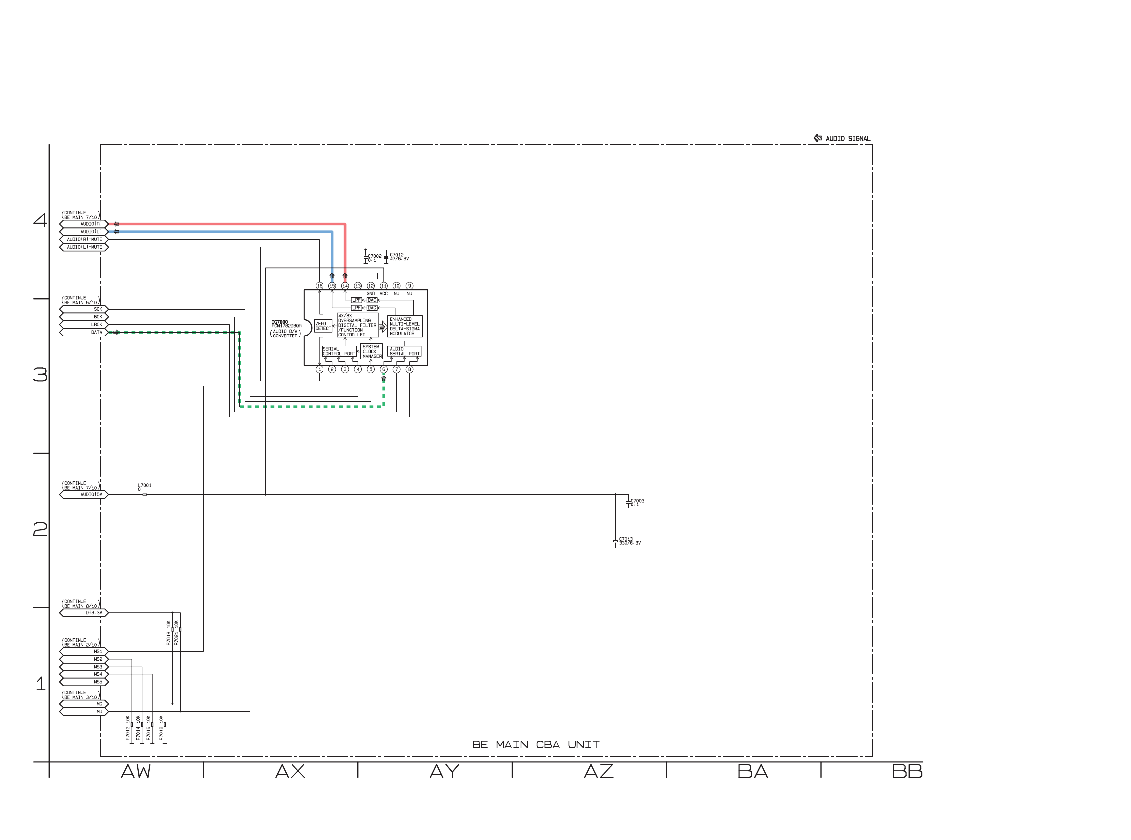
BE Main 9/10 Schematic Diagram
7877
Page 61
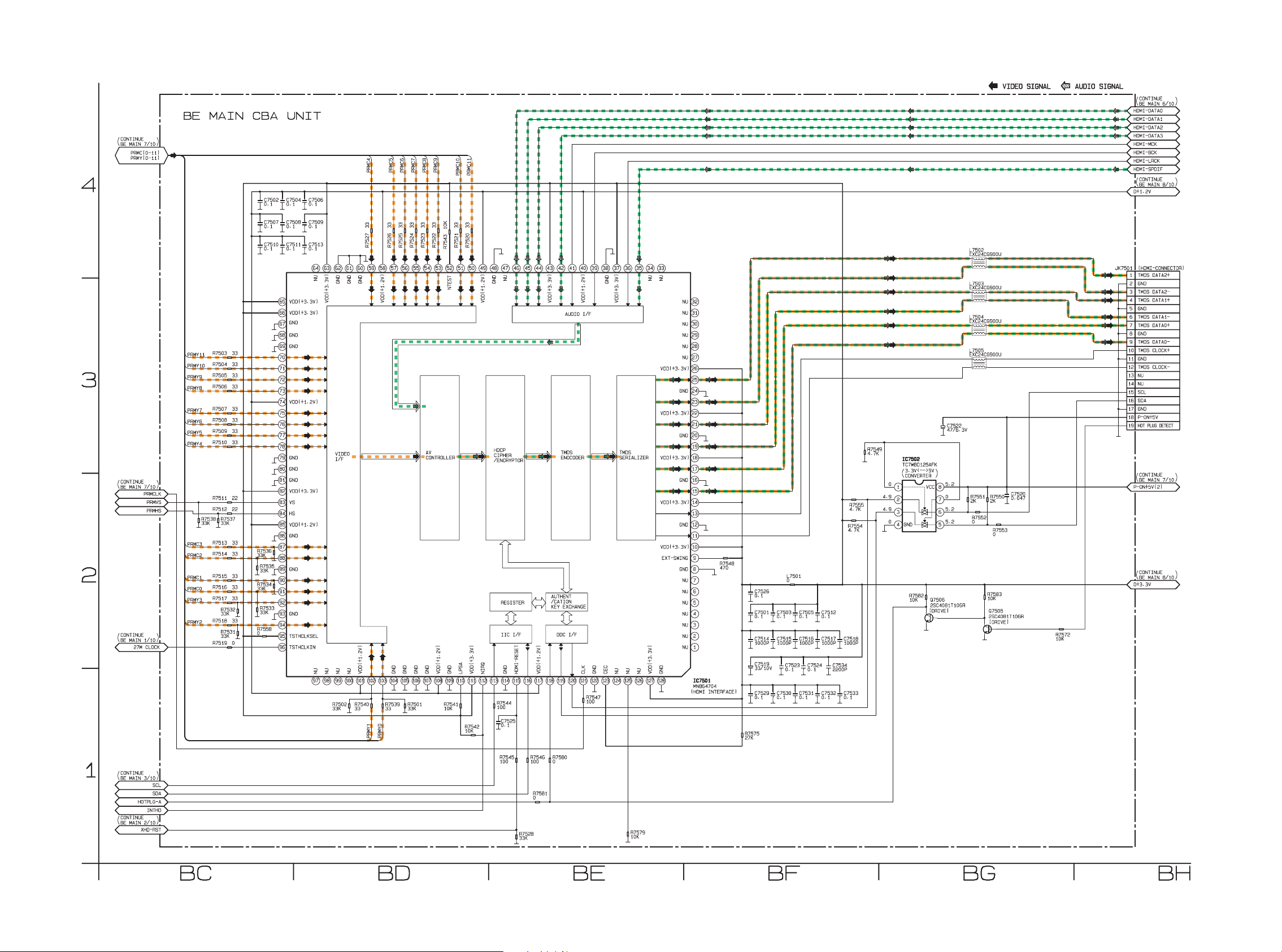
BE Main 10/10 Schematic Diagram
79 80
Page 62

PARTS LOCATION
AV CBA Top View
鉛フリー半田
半田付けには、鉛フリー半田
(Sn-Ag-Cu)
を使用してください。
Lead-free Solder
When soldering, use the Lead-free Solder (Sn-Ag-Cu).
8281
Page 63
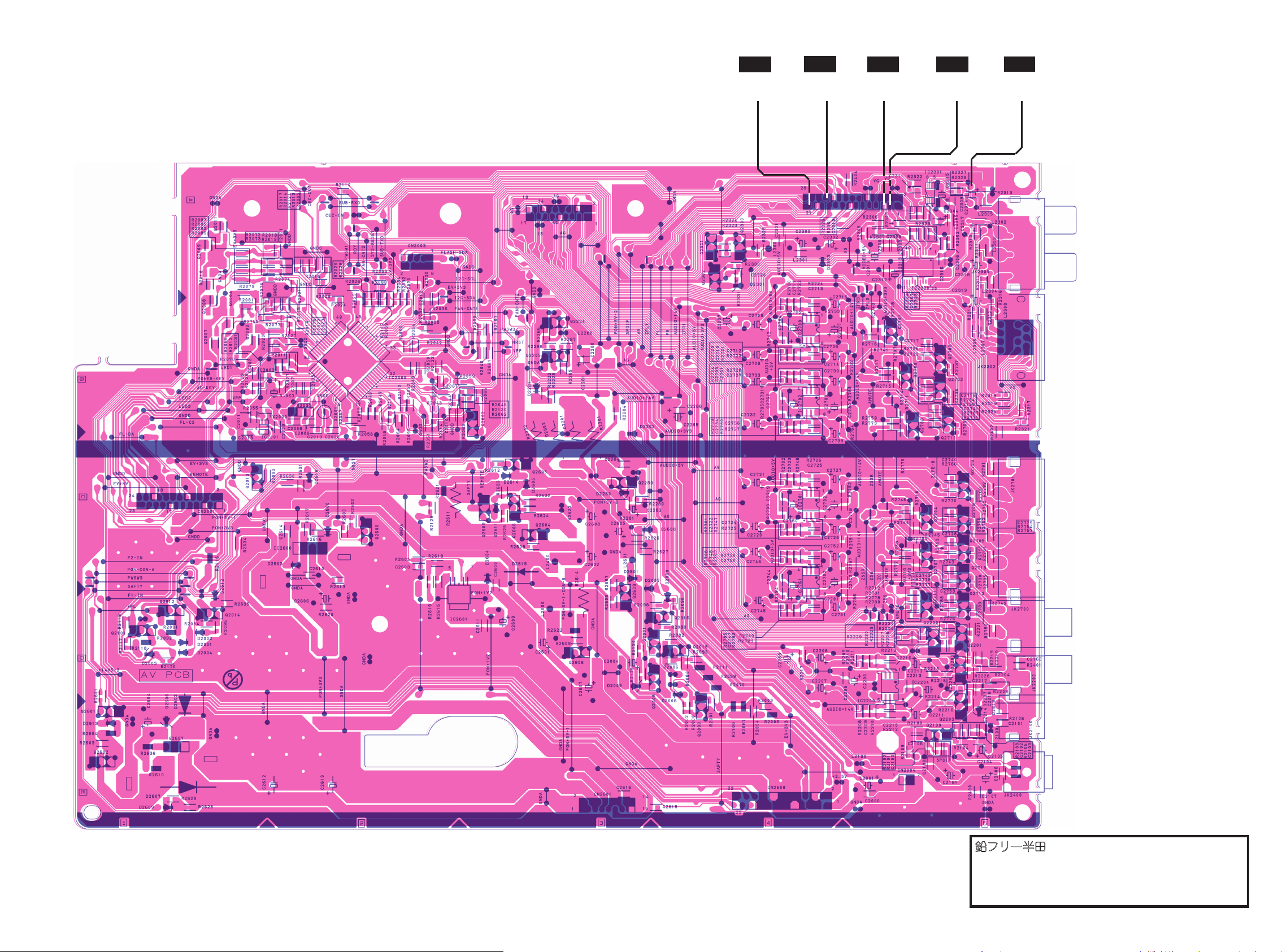
AV CBA Bottom View
PIN 27 OF
CN2000
WF7
WF5
PIN 22 OF
CN2000
WF6 WF4WF8
WF1
PIN 5 OF
CN2000
WF2WF4
PIN 3 OF
CN2000
WF3
C2314
PLUS LEAD
83 84
鉛フリー半田
半田付けには、鉛フリー半田
(Sn-Ag-Cu)
を使用してください。
Lead-free Solder
When soldering, use the Lead-free Solder (Sn-Ag-Cu).
Page 64

CAUTION !
Fixed voltage (or Auto voltage selectable) power supply circuit is used in this unit.
If Main Fuse (F1001) is blown , check to see that all components in the power supply
circuit are not defective before you connect the AC plug to the AC power supply.
Otherwise it may cause some components in the power supply circuit to fail.
CAUTION !
For continued protection against fire hazard,
replace only with the same type fuse.
NOTE:
The voltage for parts in hot circuit is measured using
hot GND as a common terminal.
Power Supply CBA Top View
鉛フリー半田
半田付けには、鉛フリー半田
Lead-free Solder
When soldering, use the Lead-free Solder (Sn-Ag-Cu).
(Sn-Ag-Cu)
を使用してください。
8685
Page 65
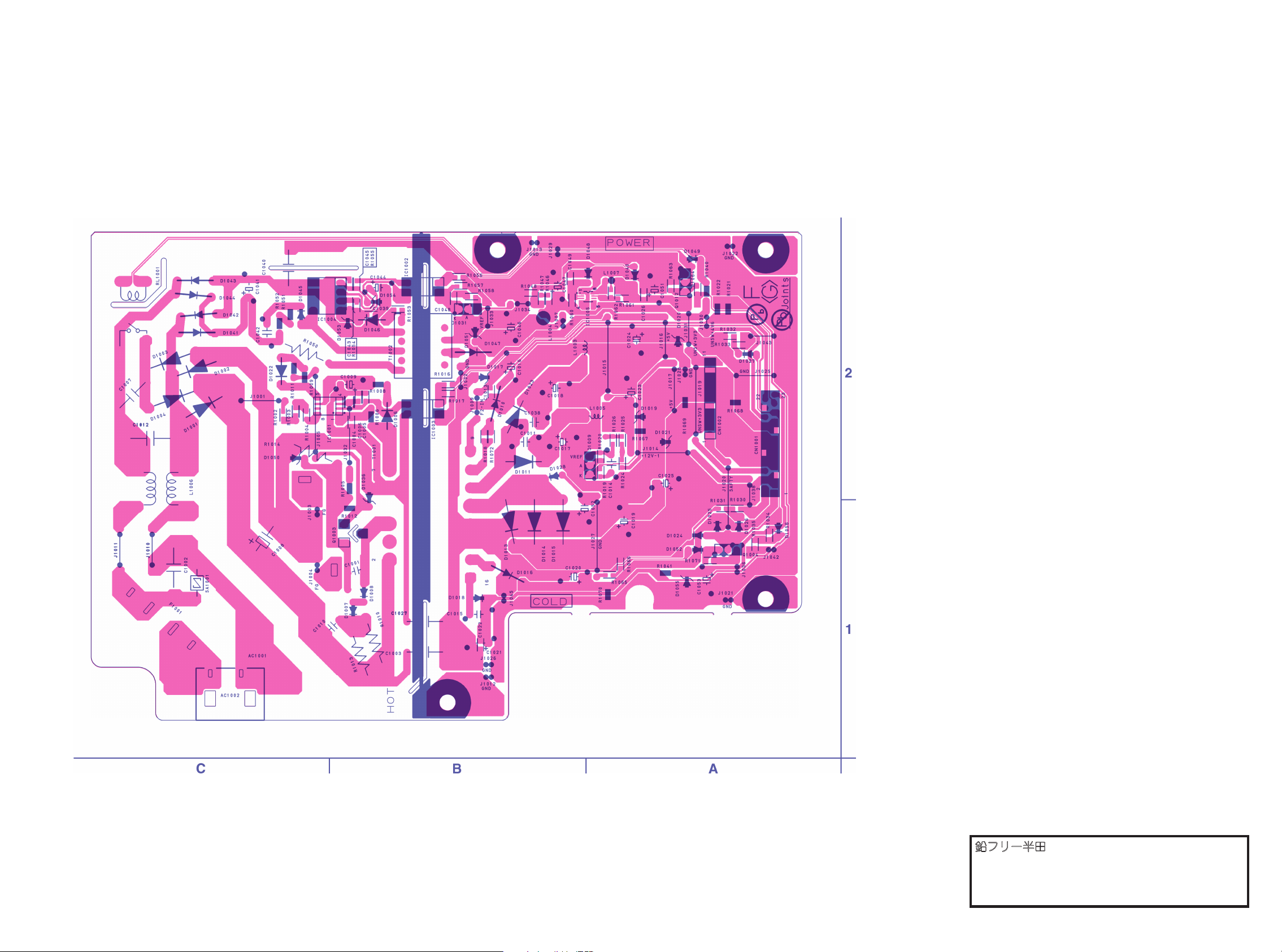
CAUTION !
Fixed voltage (or Auto voltage selectable) power supply circuit is used in this unit.
If Main Fuse (F1001) is blown , check to see that all components in the power supply
circuit are not defective before you connect the AC plug to the AC power supply.
Otherwise it may cause some components in the power supply circuit to fail.
CAUTION !
For continued protection against fire hazard,
replace only with the same type fuse.
NOTE:
The voltage for parts in hot circuit is measured using
hot GND as a common terminal.
Power Supply CBA Bottom View
87 88
鉛フリー半田
半田付けには、鉛フリー半田
(Sn-Ag-Cu)
を使用してください。
Lead-free Solder
When soldering, use the Lead-free Solder (Sn-Ag-Cu).
Page 66

Front CBA Top View
Front CBA Bottom View
鉛フリー半田
半田付けには、鉛フリー半田
(Sn-Ag-Cu)
を使用してください。
Lead-free Solder
When soldering, use the Lead-free Solder (Sn-Ag-Cu).
SD CBA Bottom View Power SW CBA Top View Power SW CBA Bottom View
9089
Page 67

EXPLODED VIEWS
Cabinet
B34
B38
B53
2L085
2L044
2L026
2L056
2L026
2L034
2L037
2L050
2L055
2L034
2L044
FM01
A4
A20
2L044
2L086
2L086
B15
2L051
2L051
2L081
2L07
0
W08
2L034
2L034
B47
B12
2L085
FE Main CBA &
BD Mechanism
Assembly
2L034
B49
2L034
2L015
2L047
W01
2L034
B14
B14
A3
B52
W07
B67
W04
2L083
2L070
2L081
2L072
2L081
2L071
A2
W09
A10
A10
B13
A1X
A6
2L038
2L018
2L082
2L082
2L082
2L082
2L082
2L082
B4
Power Supply CBA
AV CBA
BE Main CBA Unit
SD CBA
See Electrical Parts List
for parts with this mark.
Some Ref. Numbers are
not in sequence.
Front CBA
Power SW
CBA
B47
W06
A6
B54
F1001
A22
A6
B66
A6
2L043
A8
B24
A20
W11
A13
MECHANICAL PARTS LIST
PRODUCT SAFETY NOTE: Products marked with a
# have special characteristics important to safety.
Before replacing any of these components, read
carefully the product safety notice in this service
manual. Don't degrade the safety of the product
through improper servicing.
NOTE: Parts that are not assigned part numbers
(---------) are not available.
Ref. No. Description Part No.
A1X FRONT ASSEMBLY E5H70UD 1VM1 22241
A2 CHA SSIS E5H50UD 1VM225696
A3 TO P COVER E5J20 ED 1V M225860
A4 REA R PANEL E5H70UD 1VM226 036
A6 FOOT ASS EMBLY E5H50UD 1VM430199
A8 TRAY PANEL ASSEMBLY E5H70UD 1 VM225861
A10 BOTTOM GUIDE E5E 20UD 1VM224296
A20 BAR CODE LABEL E5H70UD --- -------
A22 LICENSE LABEL E5H26UD -------- --
2L015 SCREW P-TIGHT M3X8 BIND HEAD+ GBJP3080
2L018 SCREW P-TIGHT M3X8 BIND HEAD+ GBJP3080
2L026 SCRE W C-TIGHT M3X6 E561 0UD 0VM412 937A
2L027 SCRE W C-TIGHT M3X6 E561 0UD 0VM412 937A
2L034 SCREW S-TIGHT M3X6 E5E10UD 1VM429667
2L037 SCRE W C-TIGHT M3X6 E561 0UD 0VM412 937A
2L038 SCRE W C-TIGHT M3X6 E561 0UD 0VM412 937A
2L043 SCREW P-TIGHT M3X8 BIND HEAD+ GBJP3080
2L044 SCREW P-TIGHT M3X6 BIND HEAD+ GBJP3060
2L045 SCREW P-TIGHT M3X8 BIND HEAD+ GBJP3080
2L047 SCREW P-TIGHT M3X10 BIND HEAD+ GBJP3100
PACKING
S1 SID E PAD E5H70UD 1 VM122242
S2 G IFT BOX CARTON E 5H70UD 1VM328 437
S3 UNI T BAG E5500UD 0VM41168 3
ACCESSORIES
X1# OWNERS MAN UAL E5H70 UD 1VMN26373
X6 MA NGANESE DRY BATTERY R6UWC/2 SK XB0M311MS00 2
X6 DRY BATTERY ES-GR6M-C XB0M571GLP01
X10 ACCESSORY BAG E579 5ED 0VM416059
X14 AV CORD WPZ0102TM015 WPZ0102TM0 15
X14 AV CORD RCA( M*2)TO RCA(M*2) WPZ0102 LTE01
X15# AC CORD WITH A GND WIR E UL/CSA/ 162/
NO/BLACK
WAV0162LW001
X19 REMOTE CONTROL UNIT NA84 6UD NA84 6UD
X40 WARRANTY CAR D(USA) E5E30UD 1VM42898 3
X41 WARRANTY CAR D(CANADA) E5E30UD 1VM327 197
Ref. No. Description Part No.
MECHANICAL PARTS LIST
PRODUCT SAFETY NOTE: Products marked with a
# have special characteristics important to safety.
Before replacing any of these components, read
carefully the product safety notice in this service
manual. Don't degrade the safety of the product
through improper servicing.
NOTE: Parts that are not assigned part numbers
(---------) are not available.
Ref. No. Description Part No.
A1X FRONT ASSEMBLY E5H70UD 1VM1 22241
A2 CHA SSIS E5H50UD 1VM225696
A3 TO P COVER E5J20 ED 1V M225860
A4 REA R PANEL E5H70UD 1VM226 036
A6 FOOT ASS EMBLY E5H50UD 1VM430199
A8 TRAY PANEL ASSEMBLY E5H70UD 1 VM225861
A10 BOTTOM GUIDE E5E 20UD 1V M224296
A20 BAR CODE LABEL E5H70UD --- -------
A22 LICENSE LABEL E5H26UD -------- --
2L015 SCREW P-TIGHT M3X8 BIND HEAD+ GBJP3080
2L018 SCREW P-TIGHT M3X8 BIND HEAD+ GBJP3080
2L026 SCRE W C-TIGHT M3X6 E561 0UD 0VM412 937A
2L027 SCRE W C-TIGHT M3X6 E561 0UD 0VM412 937A
2L034 SCREW S-TIGHT M3X6 E5E10UD 1VM429667
2L037 SCRE W C-TIGHT M3X6 E561 0UD 0VM412 937A
2L038 SCRE W C-TIGHT M3X6 E561 0UD 0VM412 937A
2L043 SCREW P-TIGHT M3X8 BIND HEAD+ GBJP3080
2L044 SCREW P-TIGHT M3X6 BIND HEAD+ GBJP3060
2L045 SCREW P-TIGHT M3X8 BIND HEAD+ GBJP3080
2L047 SCREW P-TIGHT M3X10 BIND HEAD+ GBJP3100
2L050 SCREW P-TIGHT M3X8 BIND HEAD+ GBJP3080
2L051 SCREW P-TIGHT M3X8 BIND HEAD+ GBJP3080
2L070 B-TIGHT SCRE W M3X8 E5E00UD 1VM428563
2L071 B-TIGHT SCRE W M3X8 E5E00UD 1VM428563
2L072 SCREW TAP TIGHT M3X8 BI ND PAN
HEAD+BLK N I
GPHB30 80
2L081 S-TIGHT SCRE W M3X6 E5E00UD 1VM428564
2L082 SCREW TAP TIGHT M3X5 B IND HEAD+BLK NI GBHC3 050
2L083 S-TIGHT SCRE W M3X6 E5E00UD 1VM428564
2L085 SCRE W C-TIGHT M3X6 E561 0UD 0VM412 937A
2L086 SCRE W C-TIGHT M3X6 E561 0UD 0VM412 937A
PACKING
S1 SID E PAD E5H70UD 1 VM122242
S2 G IFT BOX CARTON E 5H70UD 1VM328 437
S3 UNI T BAG E5500UD 0VM41168 3
ACCESSORIES
X1# OWNERS MAN UAL E5H70 UD 1VMN26373
X6 MA NGANESE DRY BATTERY R6UWC/2 SK XB0M311MS00 2
X6 DRY BATTERY ES-GR6M-C XB0M571GLP01
X10 ACCESSORY BAG E579 5ED 0VM416059
X14 AV CORD WPZ0102TM015 WPZ0102TM0 15
X14 AV CORD RCA( M*2)TO RCA(M*2) WPZ0102 LTE01
X15# AC CORD WITH A GND WIR E UL/CSA/ 162/
NO/BLACK
WAV0162LW001
X19 REMOTE CONTROL UNIT NA84 6UD NA84 6UD
X40 WARRANTY CAR D(USA) E5E30UD 1VM42898 3
X41 WARRANTY CAR D(CANADA) E5E30UD 1VM327 197
Ref. No. Description Part No.
EXPLODED VIEWS
Cabinet
91
Page 68
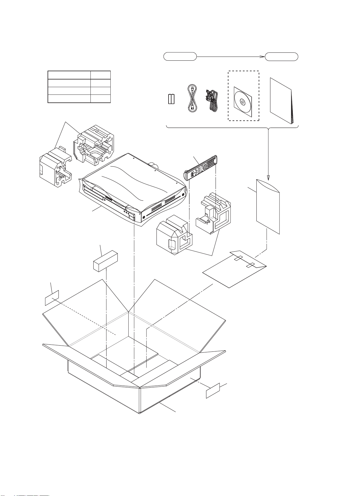
Packing
S3
S2
S1
X19
S1
X10
X1
X14 X3X6 X15
Lower Side
Upper Side
Some Ref. Numbers
are not in sequence.
A20
A20
[ A ]
S7
Comparison Chart of
Models and Marks
Model Mark
BD7003/N1B
BD7003/R1B
BD7003/S1B
A
B
C
Packing
92
Page 69
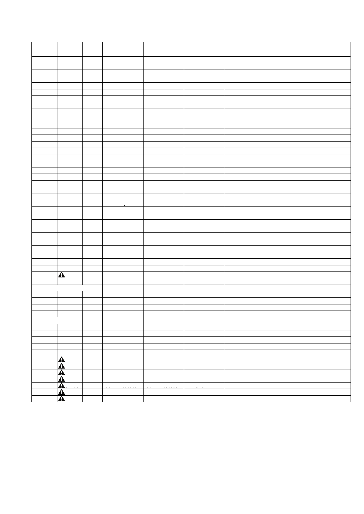
BD7003/N_R_S1B (E5J70ED/71RD/72PD)
P.W.B.
NAME
VERS.
COLOR
PART NO.
(FOR EUR)
PART NO.
(MZ)
PART NAME DESCRIPTION
A1X 9H2402001170M 9H2402001170M PANEL
FRONT ASSEMBLY E5H70UD
1VM122241
A2 ns
pnsp
CHASSIS
CHASSIS E5H50UD
1VM225696
A3 9H2403001000D 9H2403001000D LID
TOP COVER E5J20ED
1VM225860
A4
/
N1B ns
pnsp
PANEL
REAR PANEL E5J70ED
1VM226376
POS. NO.
A4
/R1Bnspnsp
PANEL
REAR PANEL E5J71RD
1VM226578
A4
/
S1B ns
pnsp
PANEL
REAR PANEL E5J72PD
1VM226580
A6 9H2407001020S 9H2407001020S LEG
FOOT ASSEMBLY E5H50UD
1VM430199
A8 9H2418001180M 9H2418001180M ESCUTCHEON
TRAY PANEL ASSEMBLY E5H70UD
1VM225861
A10 ns
pnsp
GUIDE
BOTTOM GUIDE E5E20UD
1VM224296D
A13 415510006008M 415510006008M COVER
SD COVER E5H70UD
1VM327851
FM01 9H2685001110S 9H2685001110S MOTOR
MOTOR DC FAN 2D65BL100190
MMEZR12XNR08
W01 ns
pnsp
CORD
WX1E5E10-001 11/110/AWG24
WX1E5E10-001
W04 9H2606001190S 9H2606001190S FPC
WX1E5E10-004 28/75/1.0
WX1E5E10-004
W06
9H2606001200S
9H2606001200S
FPC
WIRE ASSEMBLY FFC 15/218/1.0
WX1E5E10-012
W07 9H2606001210S 9H2606001210S FPC
WX1E5E10-007 40/240/0.5
WX1E5E10-007
W08 9H2606001220S 9H2606001220S FPC
WIRE ASSEMBLY FFC 16/125/1.0
WX1E5E20-002
W09 ns
pnsp
CORD
WIRE ASSEMBLY 15/BLACK
WX1E5E10-009
W11 ns
pnsp
CORD
WIRE ASSEMBLY 38/BLACK
WX1E5E10-011
/
N1B 9H2304001630M 9H2304001630M MECHANISM
FE MAIN CBA / BD MECHANISM ASSY N
N7JB9AEN
/
R1B ns
p
9H2304001640M MECHANISM
FE MAIN CBA / BD MECHANISM ASSY R
N7JBZARN
/
S1B ns
p
9H2304001650M MECHANISM
FE MAIN CBA / BD MECHANISM ASSY S
N7JBYAPN
/
N1B 9H2309001660M 9H2309001660M PWB ASSY
BE MAIN CBA UNIT N
1VSA20525
/
R1B ns
p
9H2309001670M PWB ASSY
BE MAIN CBA UNIT R
1VSA20587
p
/
S1B ns
p
9H2309001680M PWB ASSY
BE MAIN CBA UNIT S
1VSA20588
9H2309001690M 9H2309001690M PWB ASSY
AV/FRONT/POWER SW CBA
1VSA20385
9H2309001700M 9H2309001700M PWB ASSY
POWER SUPPLY CBA
1VSA20388
9H2189001100S 9H2189001100S PWB ASSY
SD CBA
1VSA20070
PACKING
X1
/
N1B 541110182034M 541110182034M USER GUIDE
USER GUIDE BD7003 N E5J70ED
1VMN26613
X1
/
R1B 541110182041M 541110182041M USER GUIDE
USER GUIDE BD7003 S E5J72PD
1VMN26674
X1
/
S1B ns
p
541110182041M USER GUIDE
USER GUIDE BD7003 S E5J72PD
1VMN26674
X2
/
R1B 541110182096M 541110182096M USER GUIDE
USER GUIDE BD7003 R (HANDRING BY MZE)
X3
/
N1B 541510217035M 541510217035M USER GUIDE
USER GUIDE BD7003 CD-ROM E5J70ED
1VM328837
X15 00D9H26000869 00D9H26000869 MAINS CORD
# MAINS CORD W/O GND WIRE N
WAE0162LTE01
X19 307010023039M 307010023039M UNIT KIT
REMOTE CONTROLLER RC003BD
NA847ED
NOT STANDARD SPARE PART
S1 ns
p
533610026008M CUSHION
SIDE PAD E5H70UD
1VM122242
S2 ns
p
531210058003M PACKING CASE
PACKING CASE BD7003 E5H70UD
1VM328437
S7 ns
p
00D9H26000938 CUSHION
REAR PAD E5E01UD
1VM427521
X14 ns
p
90M-ZD000470R CORD
AV CORD TSCKA-Y/RW100
WPZ0102TM015
ELECTRICAL PARTS
AV CBA
JK2100 90M-YT003370R 90M-YT003370R TERMINAL
CINCH (BLK) MSP-251V-01 NI FE LF
JXRL010LY125
JK2200 9H2643001710S 9H2643001710S TERMINAL
CINCH L 02 MSP-242V-01 NI FE
JXRL020LY152
JK2300 9H2643001290S 9H2643001290S TERMINAL
CINCH L MSP-244V10-46 NI FE
JXRL040LY145
POWER SUPPLY CBA
AC1002 9H2641001720S 9H2641001720S TERMINAL
! AC INLET YKE31-0148N
JTDC0P0JC003
C1002 90M-DF100360R 90M-DF100360R FILM CAP.
! LINE ACROSS CAP. 0.047UF/250V K
CT2E473DC016
C1003 90M-DK100850R 90M-DK100850R CER. CAP.
! SAFETY CAP. 2200PF/250V
CA2E222MR049
F1001 9H2652001730S 9H2652001730S FUSE
! TIME RAG TSC2.5A250VSVDEUC3CP
PDGAAB0W3252
SA100
1
90
M-HV
000050
R90M-HV
000050
R VARISTOR
! SURGE ABSORBER PVR-10D471KB
NVQZ10D471KB
S 00
90 000050
90 000050
SO
T1001 9H2101001740S 9H2101001740S TRANSF.
! TRANS BCK-35-0549
LTT3PE0XB042
T1002 9H2101001760S 9H2101001760S TRANSF.
! TRANS BCK-16-033T
LTT1PE0XB002
PARTS LIST
NOTE : "nsp" PART IS LISTED FOR REFERENCE ONLY, MARANTZ WILL NOT SUPPLY THESE PARTS.
93
 Loading...