

Page 1
L27/38S
Project Guide - Power Plant
Four-stroke GenSet
Page 2

Page 3

MAN Diesel & Turbo
Index
Page 1 (5)
Table of contents
Table of contents
L27/38S powerplant
I 00 Introduction
Introduction to project guide I 00 00 0 1643483-5.5
Key for engine designation I 00 05 0 1609526-0.8
Designation of cylinders I 00 15 0 1607568-0.2
Code identification for instruments I 00 20 0 1687100-5.6
Symbols for piping I 00 25 0 1655279-1.1
D 10 General information
List of capacities D 10 05 0 1689471-7.4
List of capacities D 10 05 0 1689472-9.4
Vibration limits and measurements D 10 24 0 3700395-8.3
Description of sound measurements D 10 25 0 1609510-3.5
Description of structure-borne noise D 10 25 0 1671754-6.2
Exhaust gas components D 10 28 0 1655210-7.3
Emission limits Worldbank II D 10 28 0 3700044-8.0
Moment of inertia D 10 30 0 1687148-5.2
Green Passport D 10 33 0 1699985-1.1
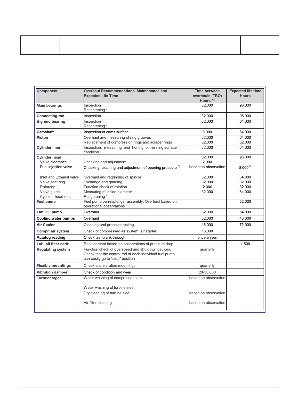
Overhaul recommendation, Maintenance and Expected life time D 10 35 0 3700340-7.1
Overhaul recommendation, Maintenance and Expected life time D 10 35 0 3700341-9.1
Overhaul recommendation, Maintenance and Expected life time D 10 35 0 3700342-0.1
Overhaul recommendation, Maintenance and Expected life time D 10 35 0 3700343-2.1
B 10 Basic diesel engine
General description B 10 01 1 1689477-8.1
Cross section B 10 01 1 1665740-7.3
Main particulars B 10 01 1 3700157-5.1
Dimensions and weights B 10 01 1 1689493-3.1
Centre of gravity B 10 01 1 1679708-8.2
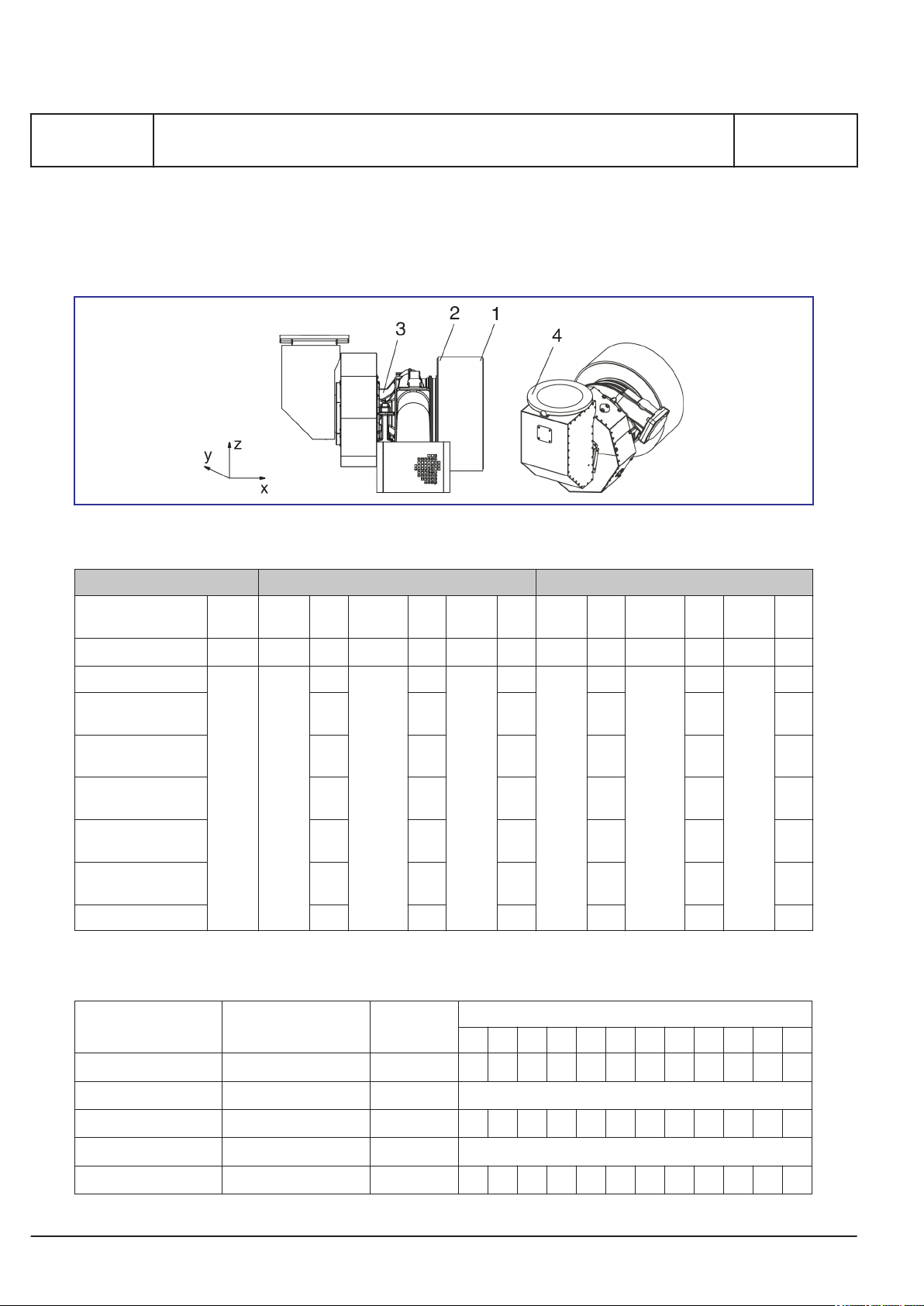
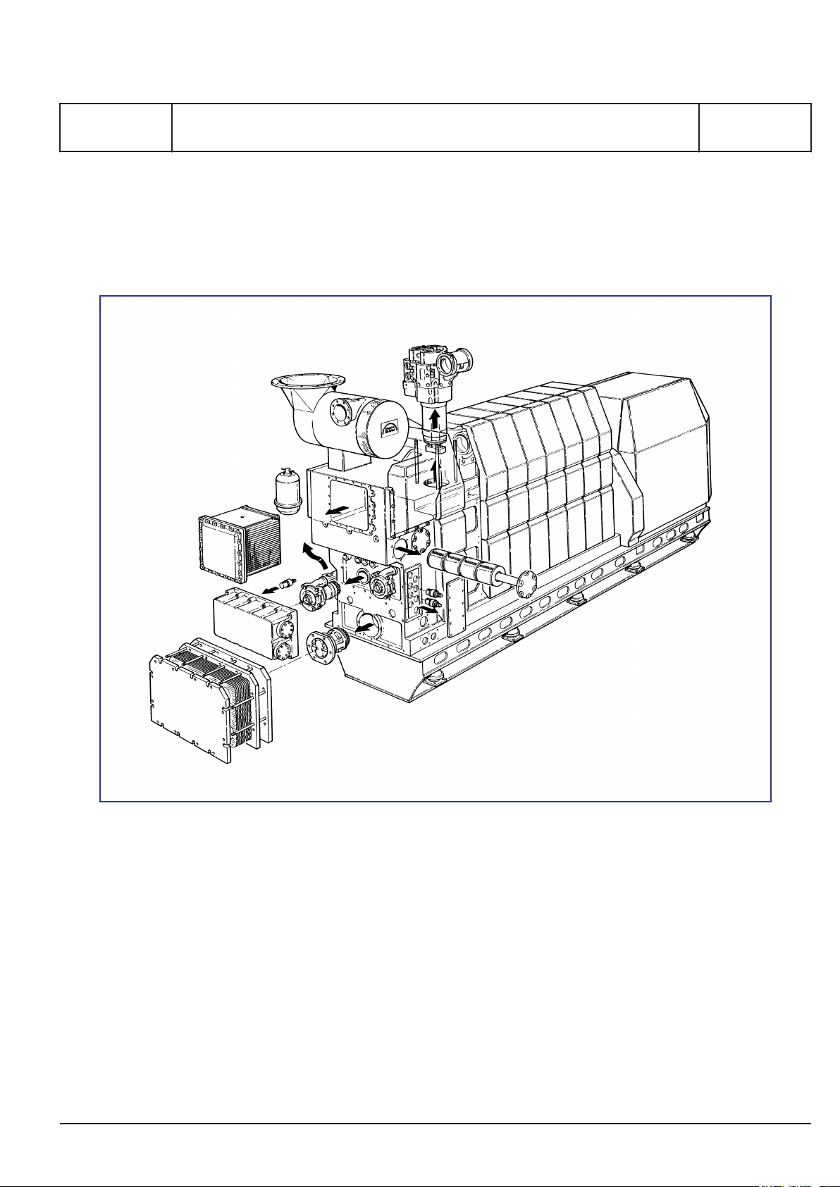
Overhaul areas B 10 01 1 1665770-6.6
2018-04-13 - en
Page 4

MAN Diesel & Turbo
Table of contents
Firing pressure comparison B 10 01 1 3700366-0.0
Engine rotation clockwise B 10 11 1 1607566-7.2
B 11 Fuel oil system
Internal fuel oil system B 11 00 0 3700163-4.1
Part-load optimisation - PLO B 11 00 0 3700499-0.1
Heavy fuel oil (HFO) specification 010.000.023-05
Marine diesel oil (MDO) specification 010.000.023-04
Gas oil / diesel oil (MGO) specification 010.000.023-01
Bio fuel specification 010.000.023-02
Explanatory notes for biofuel B 11 00 0 3700063-9.0
Crude oil specification B 11 00 0 3700246-2.0
Index
Page 2 (5)
Viscosity-temperature diagram (VT diagram) 010.000.023-06
Guidelines regarding MAN Diesel & Turbo GenSets operating on low sulphur
fuel oil
Calculation of specific fuel oil consumption (SFOC) B 11 01 0 3700405-6.2
Fuel oil consumption for emissions standard B 11 01 0 1693568-5.3
Fuel injection valve B 11 00 0 3700222-2.0
Fuel injection pump B 11 02 1 1683324-8.1
Fuel oil filter duplex E 11 08 1 1679744-6.7
MDO / MGO cooler E 11 06 1 1689458-7.3
HFO/MDO changing valves (V1 and V2) E 11 10 1 1624467-7.3
B 11 00 0 1699177-5.1
B 12 Lubricating oil system
Internal lubricating oil system B 12 00 0 1693562-4.4
Crankcase ventilation B 12 00 0 1699270-8.7
Prelubricating pump B 12 07 0 1655289-8.10
Lubricating oil (SAE 40) - Specification for heavy fuel operation (HFO) 010.000.023-11
Specification of lube oil (SAE 40) for operation with gas oil, diesel oil (MGO/
MDO) and biofuels
Specific lubricating oil system - SLOC B12150,
2018-04-13 - en
010.000.023-07
1607584-6.11
Page 5

MAN Diesel & Turbo
Index
Page 3 (5)
Treatment and maintenance of lubricating oil B12150,
Criteria for cleaning/exchange of lubricating oil B 12 15 0 1609533-1.7
Table of contents
1643494-3.11
B 13 Cooling water system
Specification of engine coolant 010.000.023-13
Coolants inspecting 010.000.002-03
Cooling water system cleaning 010.000.002-04
Quality of raw-water in cooling tower operation (additive and circulating
water)
Quality of water used in exhaust gas boiler plants B 13 00 0 1699251-7.0
Water specification for fuel-water emulsions 010.000.023-16
B 13 00 0 1699250-5.0
Internal cooling water system B 13 00 3 3700201-8.0
Internal cooling water system B 13 00 6 3700203-1.0
Design data for the external cooling water system B 13 00 0 1665774-3.7
Two string central cooling water system B 13 00 6 1699122-4.1
Expansion tank B 13 00 0 1613419-0.5
Preheater arrangement in high temperature system B 13 23 1 3700160-9.0
Expansion tank pressurized T 13 01 1 1671771-3.5
B 14 Compressed air system
Specification for compressed air 010.000.023-21
Compressed air system B 14 00 0 3700205-5.1
Compressed air system B 14 00 0 3700206-7.1
Compressed air system B 14 00 0 1655207-3.2
B 15 Combustion air system
Combustion air system B 15 00 0 1665736-1.7
Specifications for intake air (combustion air) 010.000.023-17
Engine room ventilation and combustion air B 15 00 0 1699110-4.1
Water washing of turbocharger - compressor B 15 05 1 1639499-6.0
B 16 Exhaust gas system
Exhaust gas system B 16 00 0 1655213-2.6
2018-04-13 - en
Page 6

MAN Diesel & Turbo
Table of contents
Pressure droop in exhaust gas system B 16 00 0 1624460-4.2
SCR (Selective Catalytic Reduction) B 16 00 0 3700467-8.1
Equipment to optimize performance B 16 00 0 3700546-9.0
Exhaust gas velocity B 16 01 0 3700152-6.2
Cleaning the turbocharger in service - turbine side B 16 01 3 3700418-8.1
Position of gas outlet on turbocharger B 16 02 0 1689481-3.2
B 17 Speed control system
Starting of engine B 17 00 0 1655204-8.8
Power Management - Alternator protection B 17 00 0 3700383-8.2
Engine operation under arctic conditions B 17 00 0 1689459-9.0
Actuators B 17 01 2 1689484-9.0
Index
Page 4 (5)
Actuators B 17 01 6 3700319-4.1
Actuators B 17 01 7 3700320-4.1
B 19 Safety and control system
Operation data & set points 3700061-5.9
System description V1.5
Communication from the GenSet 1.7
Modbus list B 19 00 0 3700054-4.0
Oil mist detector B 19 22 1 1699190-5.0
B 20 Foundation
Resilient mounting system for landbased generating sets B 20 00 0 1699989-9.5
B 21 Test running
Shop test programme for power plants B 21 01 1 1699986-3.2
E 23 Spare parts
Weight and dimensions of principal parts E 23 00 0 1689476-6.4
Spare parts for unrestricted service P 23 01 1 3700022-1.4
P 24 Tools
Introduction to spare part plates for tools P24000,
3700496-5.0
2018-04-13 - en
Page 7

MAN Diesel & Turbo
Index
Page 5 (5)
Standard tools (normal maintenance) P 24 01 1,
Additional tools P 24 03 9,
Hand tools P 24 05 1,
Table of contents
3700126-4.11
B 50 Alternator
Alternators for GenSets B 50 00 0 1699895-2.1
Alternator cable installation BG 50 00 0 1699865-3.4
Combinations of engine- and alternator layout BG 50 00 0 3700084-3.10
B 98 Preservation and packing
3700125-2.4
3700414-0.0
Lifting instruction P 98 05 1 1679796-1.2
2018-04-13 - en
Page 8

Page 9

MAN Diesel & Turbo
I 00 Introduction
Page 1 (1)
I 00 Introduction
2018-04-13 - en
Page 10

Page 11

MAN Diesel & Turbo
1643483-5.5
Page 1 (2)
Introduction to project guide
L23/30DF, L16/24S, L21/31S, L23/30S, L27/38S, L28/32S, L28/32S-DF, L28/32DF,
V28/32H, V28/32S, L16/24, L21/31, L23/30H, L27/38, L28/32H
Introduction
Our project guides provide customers and consultants with information and data when planning new plants
incorporating four-stroke engines from the current MAN Diesel & Turbo engine programme. On account of the
modifications associated with upgrading of our project guides, the contents of the specific edition hereof will
remain valid for a limited time only.
Every care is taken to ensure that all information in this project guide is present and correct.
For actual projects you will receive the latest project guide editions in each case together with our quotation
specification or together with the documents for order processing.
All figures, values, measurements and/or other information about performance stated in the project guides are
for guidance only and shall not be used for detailed design purposes or as a substitute for specific drawings
and instructions prepared for such purposes. MAN Diesel & Turbo makes no representations or warranties
either express or implied, as to the accuracy, completeness, quality or fitness for any particular purpose of the
information contained in the project guides.
MAN Diesel & Turbo will issue an Installation Manual with all project related drawings and installation instructions when the contract documentation has been completed.
The Installation Manual will comprise all necessary drawings, piping diagrams, cable plans and specifications of
our supply.
I 00 00 0
All data provided in this document is non-binding. This data serves informational purposes only and is especially not
guaranteed in any way.
Depending on the subsequent specific individual projects, the relevant data may be subject to changes and will be
assessed and determined individually for each project. This will depend on the particular characteristics of each
individual project, especially specific site and operational conditions.
If this document is delivered in another language than English and doubts arise concerning the translation, the English text shall prevail.
Original instructions
2016.01.06
Page 12

MAN Diesel & Turbo
I 00 00 0
Introduction to project guide
L23/30DF, L16/24S, L21/31S, L23/30S, L27/38S, L28/32S, L28/32S-DF, L28/32DF,
V28/32H, V28/32S, L16/24, L21/31, L23/30H, L27/38, L28/32H
Code numbers
Code letter: The code letter indicates the contents of the documents:
B : Basic Diesel engine / built-on engine
D : Designation of plant
E : Extra parts per engine
G : Generator
I : Introduction
P : Extra parts per plant
1643483-5.5
Page 2 (2)
Function/system number: A distinction is made between the various chapters and systems, e.g.: Fuel oil system, monitoring equipment, foundation, test running, etc.
Sub-function: This figure occurs in variants from 0-99.
Choice number: This figure occurs in variants from 0-9:
0 : General information 1 : Standard
2-8 : Standard optionals 9 : Optionals
Further, there is a table of contents for each chapter and the pages follow immediately afterwards.
Drawing No: Each document has a drawing number including revision number i.e. 1643483-5.5.
Release date: The release date of the document Year.Month.Date. This is the date the document has been
created.
Notice: When refering to a document, please state both Drawing No including revision No and Release
date.
Copyright 2011 © MAN Diesel & Turbo, branch of MAN Diesel & Turbo SE, Germany, registered with the Danish
Commerce and Companies Agency under CVR Nr.: 31611792, (herein referred to as “MAN Diesel & Turbo”).
This document is the product and property of MAN Diesel & Turbo and is protected by applicable copyright laws.
Subject to modification in the interest of technical progress. Reproduction permitted provided source is given.
2016.01.06
Page 13
MAN Diesel & Turbo
1609526-0.8
Page 1 (1)
L27/38S, L16/24S, L21/31S, L23/30S, L28/32S, L23/30DF, L28/32DF, V28/32H,
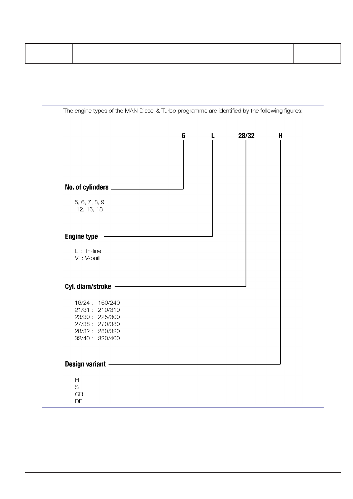
Key for engine designation
Key for engine designation
V28/32S, L16/24, L21/31, L23/30H, L27/38, L28/32H
I 00 05 0
2015.11.27
Page 14

Page 15
MAN Diesel & Turbo
1607568-0.2
Page 1 (1)
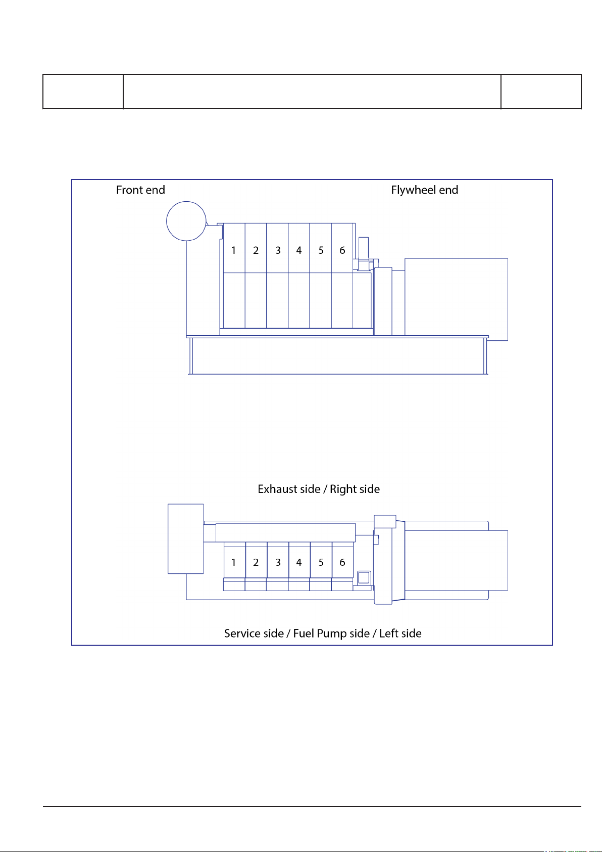
General
Designation of cylinders
I 00 15 0
L16/24S, L21/31S, L23/30S, L23/30DF, L28/32S, L27/38S, L28/32DF, L16/24,
L21/31, L23/30H, L27/38, L28/32H
2016.08.24
Page 16

Page 17
MAN Diesel & Turbo
1687100-5.6
Page 1 (3)
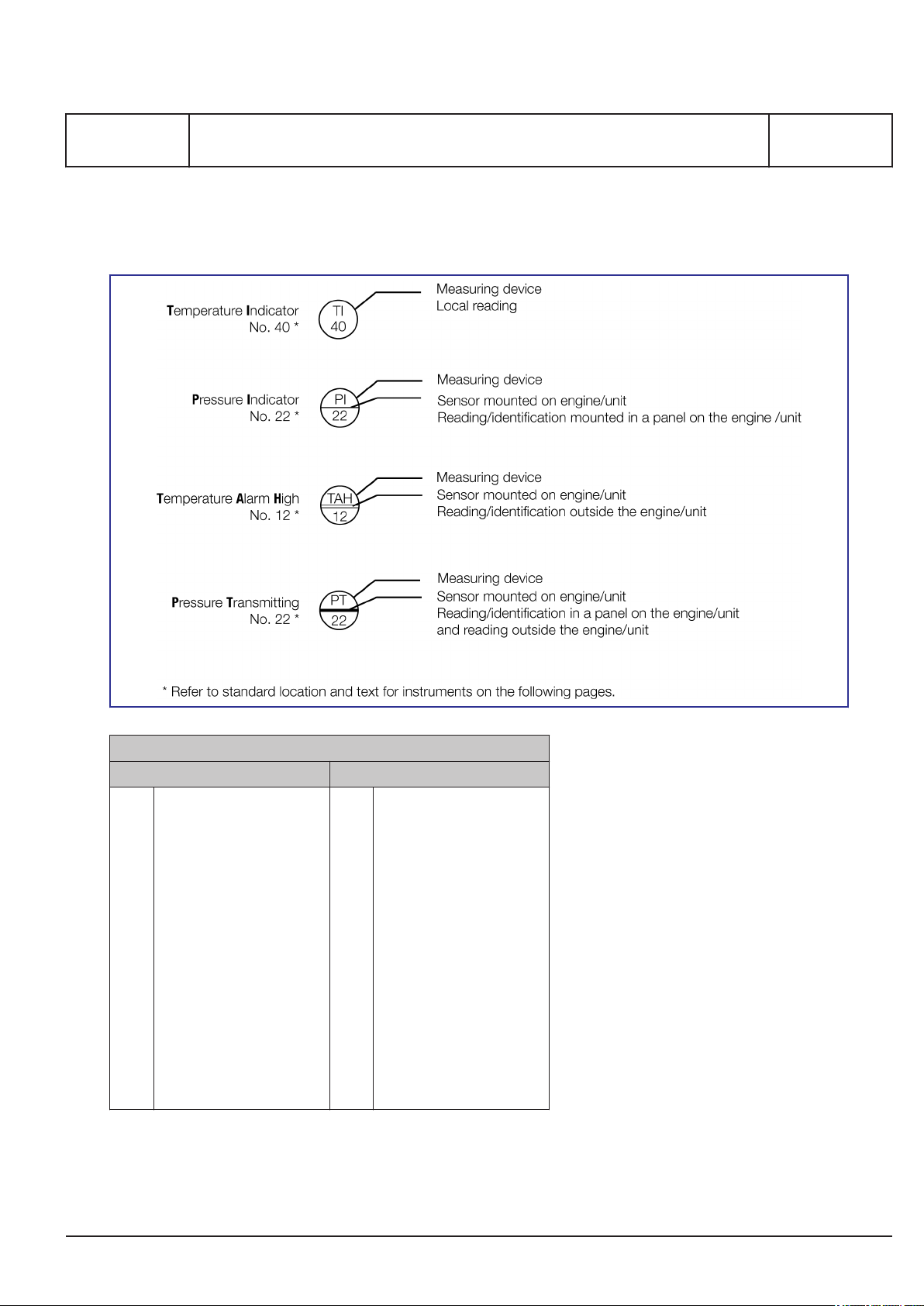
Explanation of symbols
Code identification for instruments
I 00 20 0
L16/24S, L27/38S, L21/31S, L23/30S, L23/30DF, L28/32S, L28/32DF, V28/32H,
V28/32S, L16/24, L21/31, L23/30H, L27/38, L28/32H
Specification of letter code for measuring devices
1st letter Following letters
F
Flow
L
Level
P
Pressure
S
Speed, System
T
Temperature
U
Voltage
V
Viscosity
X
Sound
Z
Position
A
Alarm
D
Differential
E
Element
H
High
I
Indicating
L
Low
S
Switching, Stop
T
Transmitting
X
Failure
V
Valve, Actuator
2018.03.27
Page 18

MAN Diesel & Turbo
I 00 20 0
Code identification for instruments
L16/24S, L27/38S, L21/31S, L23/30S, L23/30DF, L28/32S, L28/32DF, V28/32H,
V28/32S, L16/24, L21/31, L23/30H, L27/38, L28/32H
Standard text for instruments
Diesel engine/alternator
LT water system
01
inlet to air cooler
02
outlet from air cooler
03
outlet from lub. oil cooler
HT water system
10
inlet to engine
10A
FW inlet to engine
11
outlet from each cylinder
12
outlet from engine
13
inlet to HT pump
Lubricating oil system
04
inlet to alternator
05
outlet from alternator
06
outlet from fresh water cooler
(SW)
14
inlet to HT air cooler
14A
FW inlet to air cooler
14B
FW outlet from air cooler
15
outlet from HT system
16
outlet from turbocharger
07
inlet to lub. oil cooler
08
inlet to fresh water cooler
09
17
outlet from fresh water cooler
18
inlet to fresh water cooler
19
preheater
19A
inlet to prechamber
19B
outlet from prechamber
1687100-5.6
Page 2 (3)
20
inlet to cooler
21
outlet from cooler/inlet to filter
22
outlet from filter/inlet to engine
23
inlet to turbocharger
23B
outlet from turbocharger
Charging air system
30
inlet to cooler
31
outlet from cooler
32
jet assist system
33
outlet from TC filter/inlet to TC
compr.
Fuel oil system
40
inlet to engine
41
outlet from engine
42
leakage
43
inlet to filter
Nozzle cooling system
50
inlet to fuel valves
51
outlet from fuel valves
52
53
24
sealing oil - inlet engine
25
prelubricating
26
inlet rocker arms and roller
guides
27
intermediate bearing/alternator
bearing
34
charge air conditioning
35
surplus air inlet
36
inlet to turbocharger
37
charge air from mixer
44
outlet from sealing oil pump
45
fuel-rack position
46
inlet to prechamber
47
54
55
valve timing
56
injection timing
57
earth/diff. protection
2829level in base frame
main bearings
3839Ambient temperature
4849
5859oil splash
alternator load
Exhaust gas system
60
outlet from cylinder
61
outlet from turbocharger
62
inlet to turbocharger
63
combustion chamber
64
6869
65
66
67
2018.03.27
Page 19

MAN Diesel & Turbo
1687100-5.6
Page 3 (3)
Compressed air system
70
inlet to engine
71
inlet to stop cylinder
72
inlet to balance arm unit
73
control air
Load speed
80
overspeed air
81
overspeed
82
emergency stop
83
engine start
Miscellaneous
91
natural gas - inlet to engine
92
oil mist detector
93
knocking sensor
94
cylinder lubricating
Code identification for instruments
I 00 20 0
L16/24S, L27/38S, L21/31S, L23/30S, L23/30DF, L28/32S, L28/32DF, V28/32H,
V28/32S, L16/24, L21/31, L23/30H, L27/38, L28/32H
74
inlet to reduction valve
75
microswitch for turning gear
76
inlet to turning gear
77
waste gate pressure
84
engine stop
85
microswitch for overload
86
shutdown
87
ready to start
95
voltage
96
switch for operating location
97
remote
98
alternator winding
7879inlet to sealing oil system
88
index - fuel injection pump
89
turbocharger speed
90
engine speed
99
common alarm
100
inlet to MDO cooler
101
outlet to MDO cooler
102
alternator cooling air
2018.03.27
Page 20

Page 21
MAN Diesel & Turbo
1655279-1.1
Page 1 (10)
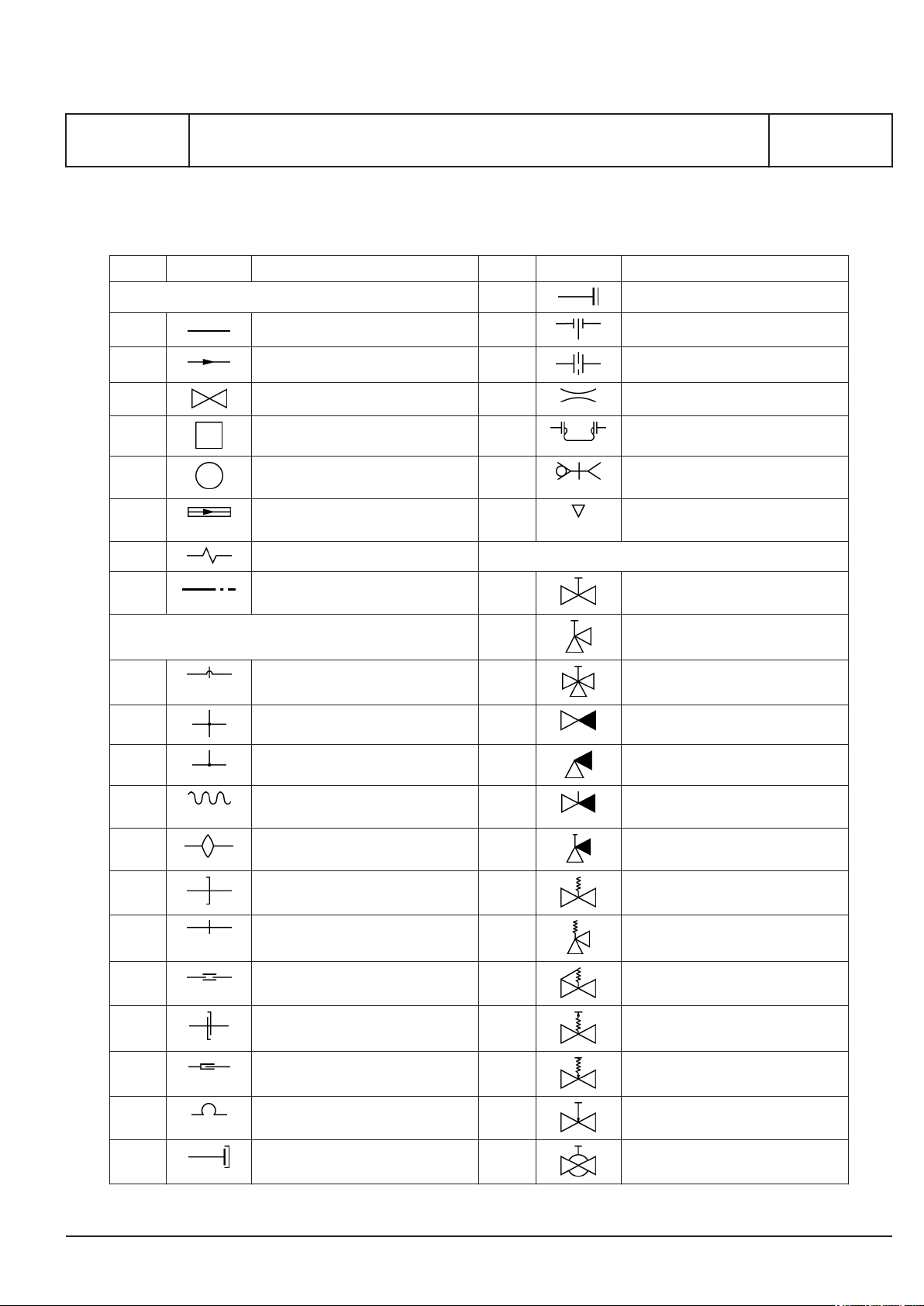
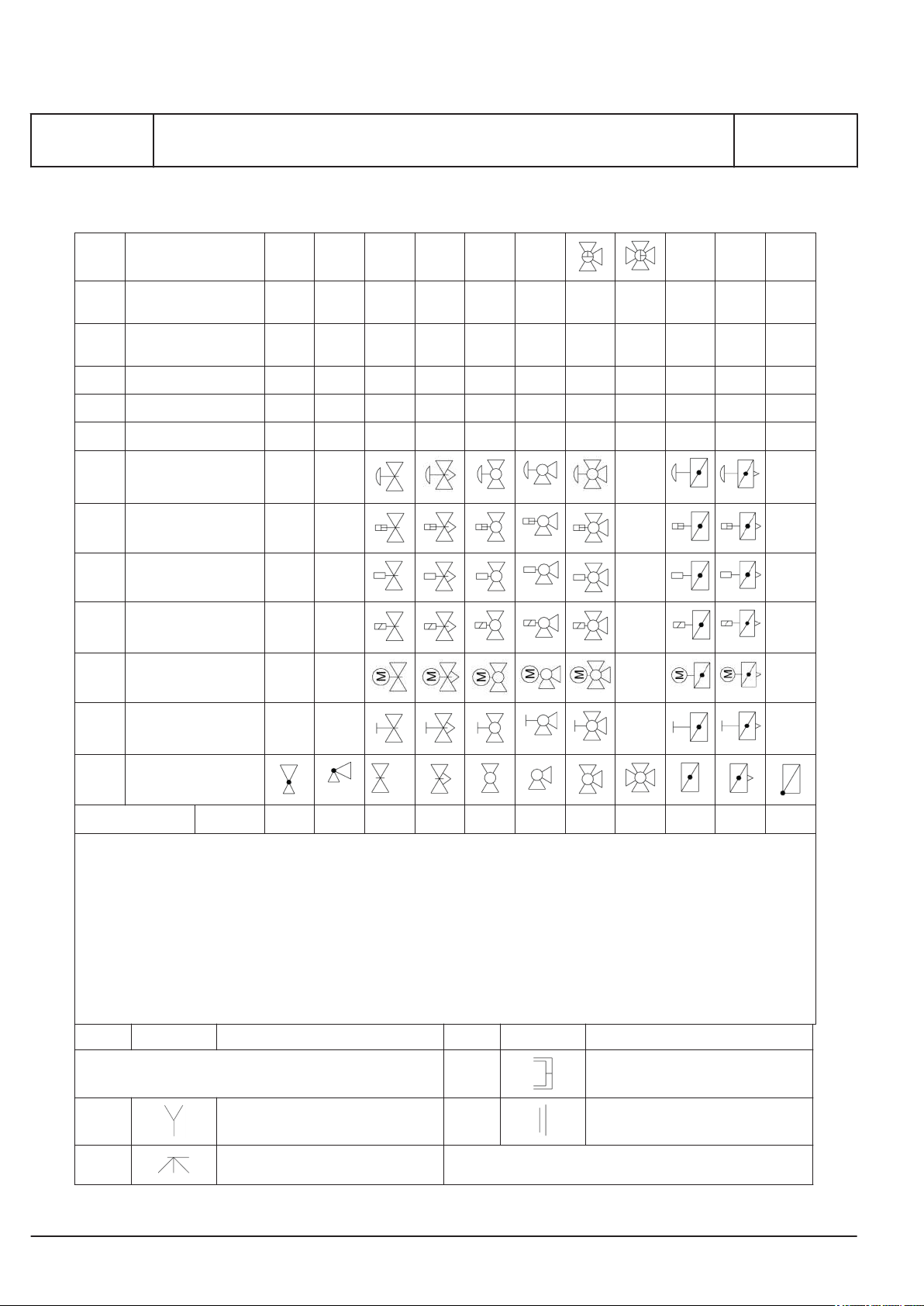
Symbols for piping
L27/38S, L16/24, L16/24S, L21/31, L21/31S, L23/30H, L23/30S, L23/30DF,
L28/32H, L28/32S, V28/32H, V28/32S, L27/38, L28/32DF
General
No Symbol Symbol designation No Symbol Symbol designation
1. GENERAL CONVENTIONAL SYMBOLS 2.13 Blank flange
1.1 Pipe 2.14 Spectacle flange
1.2 Pipe with indication of direction flow 2.15 Orifice
1.3 Valves, gate valves, cocks and flaps 2.16 Orifice
1.4 Appliances 2.17 Loop expansion joint
1.5 Indicating and measuring instruments
1.6 High-pressure pipe 2.19 Pneumatic flow or exhaust to
1.7 Tracing 3. VALVES, GATE VALVES, COCKS AND FLAPS
2.18 Snap coupling
I 00 25 0
atmosphere
1.8 Enclosure for several components
as-sembled in one unit
2. PIPES AND PIPE JOINTS 3.2 Valve, angle
2.1 Crossing pipes, not connected 3.3 Valve, three-way
2.2 Crossing pipes, connected 3.4 Non-return valve (flap), straight
2.3 Tee pipe 3.5 Non-return valve (flap), angle
2.4 Flexible pipe 3.6 Non-return valve (flap), straight
2.5 Expansion pipe (corrugated) general 3.7 Non-return valve (flap), angle, screw
2.6 Joint, screwed 3.8 Safety valve
2.7 Joint, flanged 3.9 Angle safety valve
2.8 Joint, sleeve 3.10 Self-closing valve
2.9 Joint, quick-releasing 3.11 Quick-opening valve
3.1 Valve, straight through
screw down
down
2.10 Expansion joint with gland 3.12 Quick-closing valve
2.11 Expansion pipe 3.13 Regulating valve
2.12 Cap nut 3.14 Ball valve (cock)
2015.11.17
Page 22
MAN Diesel & Turbo
I 00 25 0
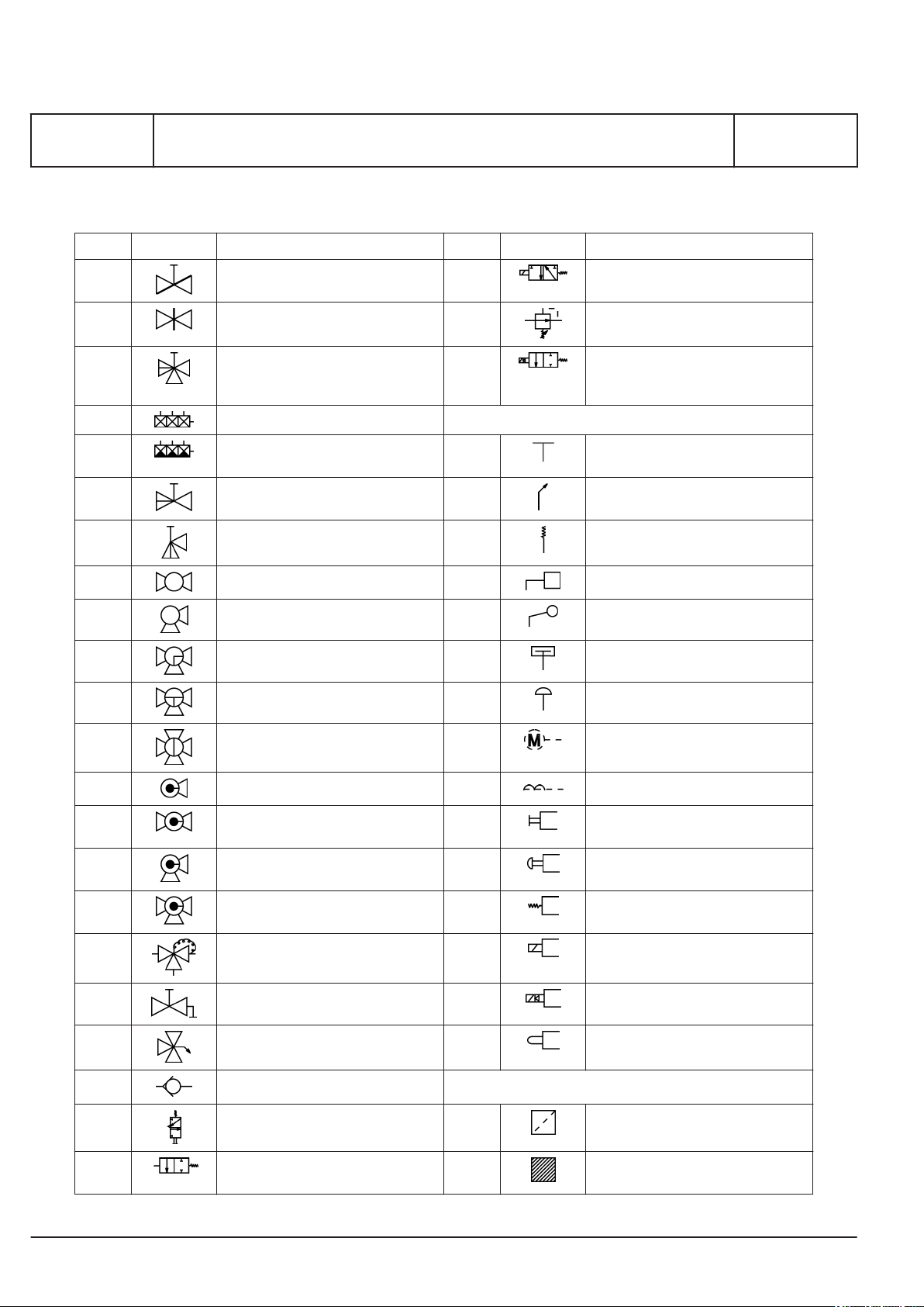
Symbols for piping
L27/38S, L16/24, L16/24S, L21/31, L21/31S, L23/30H, L23/30S, L23/30DF,
L28/32H, L28/32S, V28/32H, V28/32S, L27/38, L28/32DF
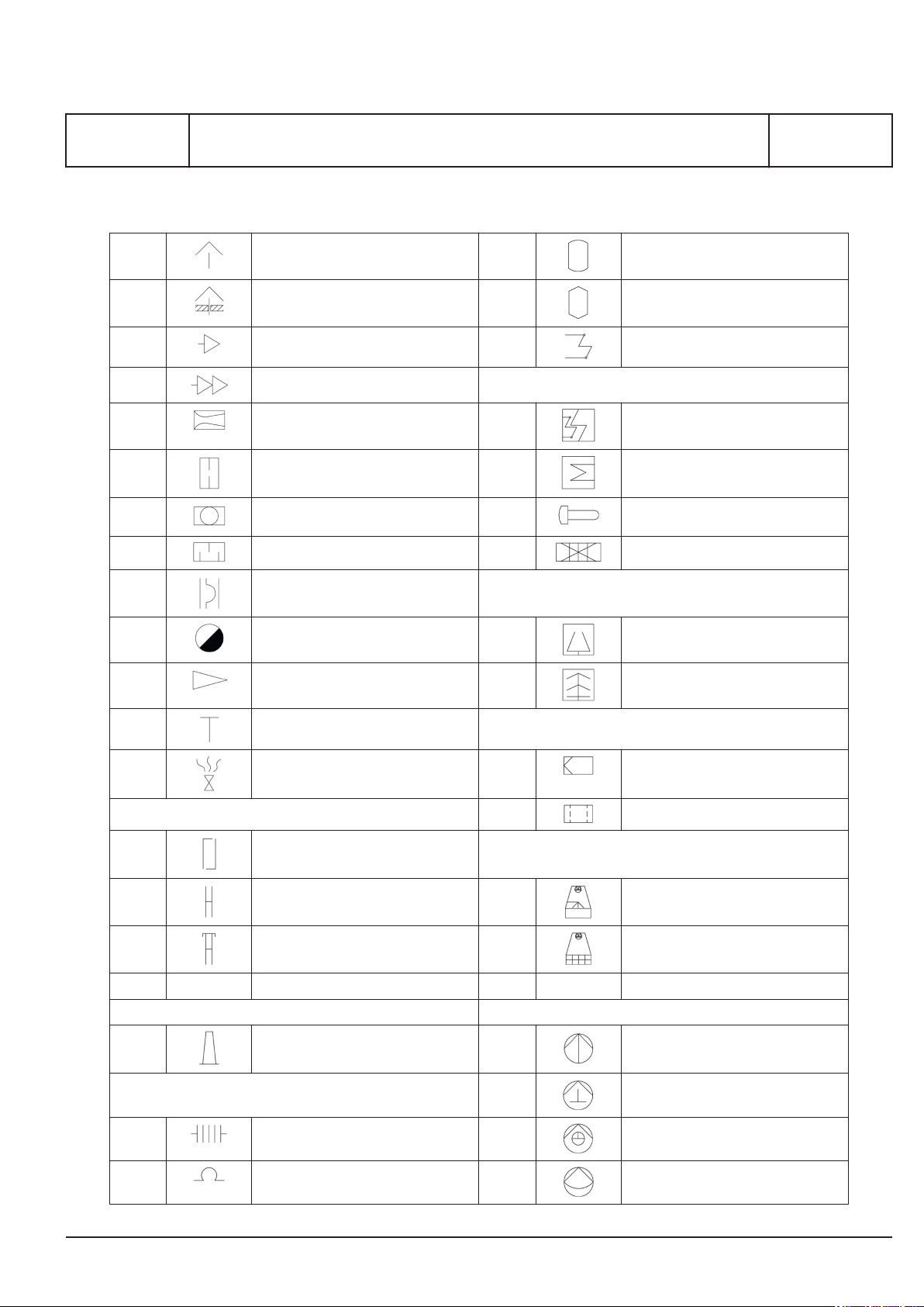
No Symbol Symbol designation No Symbol Symbol designation
3.15 Butterfly valve 3.37 3/2 spring return valve contr. by solenoid
3.16 Gate valve 3.38 Reducing valve (adjustable)
3.17 Double-seated changeover valve 3.39 On/off valve controlled by solenoid
and pilot directional valve and with
spring return
3.18 Suction valve chest 4. CONTROL AND REGULATION PARTS
3.19 Suction valve chest with non-return
valves
3.20 Double-seated changeover valve,
straight
3.21 Double-seated changeover valve,
angle
3.22 Cock, straight through 4.4 Mass
4.1 Fan-operated
4.2 Remote control
4.3 Spring
1655279-1.1
Page 2 (10)
3.23 Cock, angle 4.5 Float
3.24 Cock, three-way, L-port in plug 4.6 Piston
3.25 Cock, three-way, T-port in plug 4.7 Membrane
3.26 Cock, four-way, straight through in
plug
3.27 Cock with bottom connection 4.9 Electromagnetic
3.28 Cock, straight through, with bottom
conn.
3.29 Cock, angle, with bottom connec-
tion
3.30 Cock, three-way, with bottom con-
nection
3.31 Thermostatic valve 4.13 Solenoid
3.32 Valve with test flange 4.14 Solenoid and pilot directional valve
3.33 3-way valve with remote control
(actuator)
4.8 Electric motor
4.10 Manual (at pneumatic valves)
4.11 Push button
4.12 Spring
4.15 By plunger or tracer
3.34 Non-return valve (air) 5. APPLIANCES
3.35 3/2 spring return valve, normally
closed
3.36 2/2 spring return valve, normally
closed
5.1 Mudbox
5.2 Filter or strainer
2015.11.17
Page 23
MAN Diesel & Turbo
1655279-1.1
Page 3 (10)
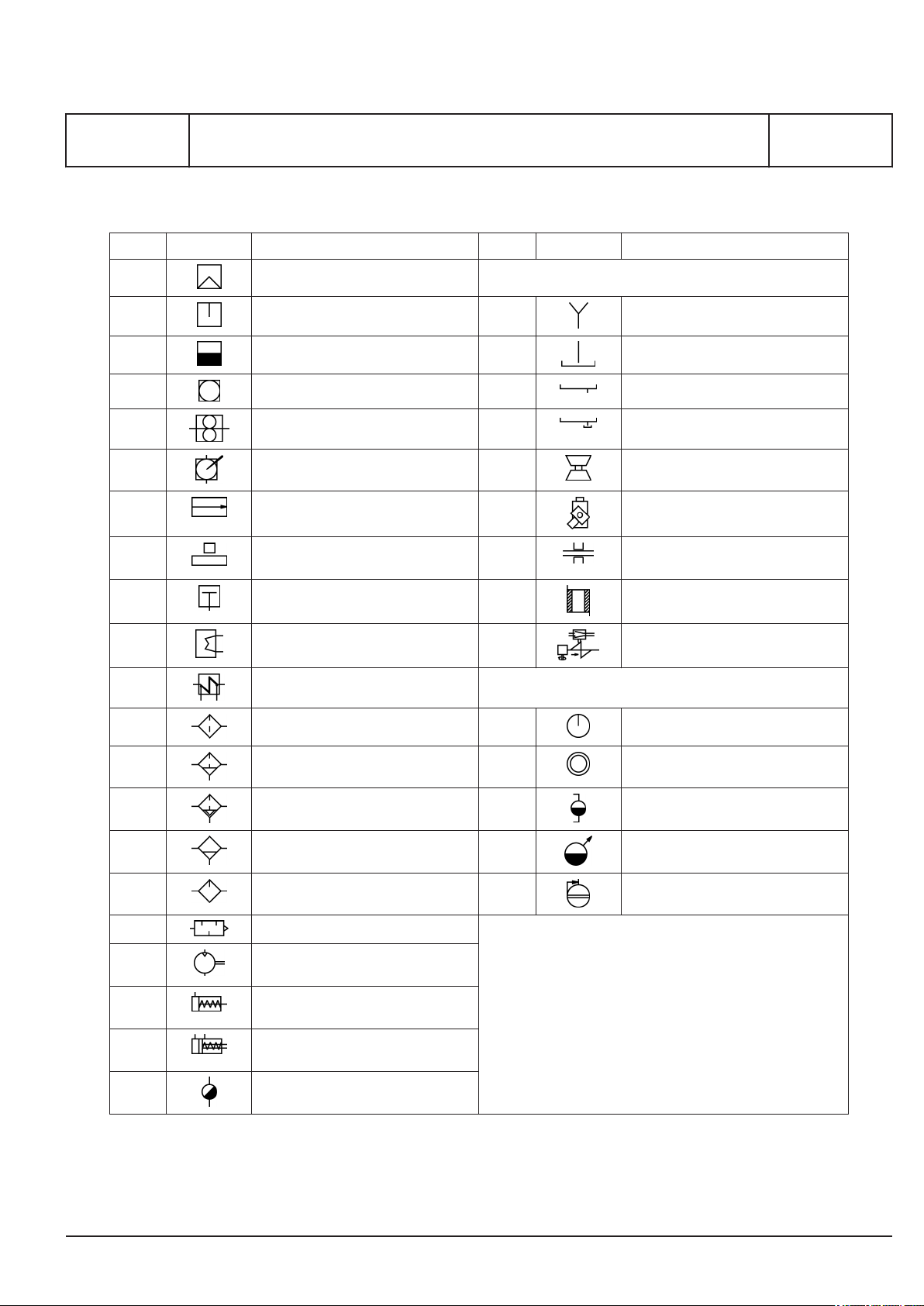
Symbols for piping
L27/38S, L16/24, L16/24S, L21/31, L21/31S, L23/30H, L23/30S, L23/30DF,
L28/32H, L28/32S, V28/32H, V28/32S, L27/38, L28/32DF
No Symbol Symbol designation No Symbol Symbol designation
5.3 Magnetic filter 6. FITTINGS
5.4 Separator 6.1 Funnel / waste tray
5.5 Steam trap 6.2 Drain
5.6 Centrifugal pump 6.3 Waste tray
5.7 Gear or screw pump 6.4 Waste tray with plug
5.8 Hand pump (bucket) 6.5 Turbocharger
5.9 Ejector 6.6 Fuel oil pump
5.10 Various accessories (text to be
added)
5.11 Piston pump 6.8 Water jacket
6.7 Bearing
I 00 25 0
5.12 Heat exchanger 6.9 Overspeed device
5.13 Electric preheater 7. READING INSTR. WITH ORDINARY DESIGNATIONS
5.14 Air filter 7.1 Sight flow indicator
5.15 Air filter with manual control 7.2 Observation glass
5.16 Air filter with automatic drain 7.3 Level indicator
5.17 Water trap with manual control 7.4 Distance level indicator
5.18 Air lubricator 7.5 Recorder
5.19 Silencer
5.20 Fixed capacity pneumatic motor
with direction of flow
5.21 Single acting cylinder with spring
returned
5.22 Double acting cylinder with spring
returned
5.23 Steam trap
2015.11.17
Page 24

MAN Diesel & Turbo
I 00 25 0
Symbols for piping
L27/38S, L16/24, L16/24S, L21/31, L21/31S, L23/30H, L23/30S, L23/30DF,
L28/32H, L28/32S, V28/32H, V28/32S, L27/38, L28/32DF
List of Symbols
Pipe dimensions and piping signature
Pipe dimenesions
A : Welded or seamless steel pipes. B : Seamless precision steel pipes or Cu-pipes.
Normal
Diameter
DN
15
20
25
32
40
50
65
80
90
100
125
150
175
200
General
Pump, general DIN 2481 Ballcock
Outside
Diameter
mm
21.3
26.9
33.7
42.4
48.3
60.3
76.1
88.9
101.6
114.3
139.7
168.3
193.7
219.1
Wall
Thickness
mm
In accordance
with classification or other
rules
Stated: Outside diameter and wall thickness i.e. 18 x 2
Piping
: Built-on engine/Gearbox
: Yard supply
Items connected by thick lines are built-on engine/ gearbox.
1655279-1.1
Page 4 (10)
General
Centrifugal pump DIN 2481 Cock, three-way, L-port
Centrifugal pump with electric
motor
Gear pump DIN 2481 Spectacle flange DIN 2481
Screw pump DIN 2481 Spectacle flange, open DIN 2481
Screw pump with electric
motor
Compressor ISO 1219 Orifice
Heat exchanger DIN 2481 Flexible pipe
Electric pre-heater DIN 2481 Centrifuge DIN 28.004
DIN 2481 Double-non-return valve DIN 74.253
DIN 2481 Spectacle flange, closed DIN 2481
2015.11.17
Page 25

MAN Diesel & Turbo
1655279-1.1
Page 5 (10)
Symbols for piping
I 00 25 0
L27/38S, L16/24, L16/24S, L21/31, L21/31S, L23/30H, L23/30S, L23/30DF,
L28/32H, L28/32S, V28/32H, V28/32S, L27/38, L28/32DF
Heating coil DIN 8972 Suction bell
Non-return valve Air vent
Butterfly valve Sight glass DIN 28.004
Gate valve Mudbox
Relief valve Filter
Quick-closing valve Filter with water trap ISO 1219
Self-closing valve Typhon DIN 74.253
Back pressure valve Pressure reducing valve (air) ISO 1219
Shut off valve Oil trap DIN 28.004
Thermostatic valve Accumulator
Pneumatic operated valve Pressure reducing valve with
pressure gauge
General
Specification of letter code for measuring devices
2015.11.17
Page 26

MAN Diesel & Turbo
I 00 25 0
Symbols for piping
L27/38S, L16/24, L16/24S, L21/31, L21/31S, L23/30H, L23/30S, L23/30DF,
L28/32H, L28/32S, V28/32H, V28/32S, L27/38, L28/32DF
1st letter Following letters
D : Density
E : Electric
F : Flow
L : Level
M ; Moisture
P : Pressure
S : Speed
T : Temperature
V : Viscosity
Z : Position
(ISO 3511/I-1977(E))
The presence of a measuring device on a schematic diagram does not necessarily indicate that the device is included in our scope of supply.
For each plant. The total extent of our supply will be stated
formally.
General
Specification of ID-no code for measuring signals/devices
1st digit 2nd digit
Refers to the main system to which the signal is related. Refers to the auxillary system to which the signal is rela-
1xxx : Engine x0xx : LT cooling water
2xxx : Gearbox x1xx : HT cooling water
3xxx : Propeller equipment x2xx : Oil systems (lub. oil, cooling oil, clutch oil, servo
4xxx : Automation equipment x3xx : Air systems (starting air, control air, charging air)
5xxx : Other equipment, not related to the propulsion
plant
x5xx :
x6xx : Exhaust gas system
x7xx : Power control systems (start, stop, clutch, speed,
x8xx : Sea water
x9xx : Miscellaneous (shaft, stern tube, sealing)
The last two digits are numeric ID for devices referring to the same main and aux. system.
A : Alarm
D : Difference
E : Transducer
H : High
I : Indicating
L : Low
N : Closed
O : Open
S : Switching, shut down
T : Transmitter
X : Failure
C : Controlling
Z : Emergency/safety acting
ted.
oil)
x4xx : Fuel systems (fuel injection, fuel oil)
pitch)
1655279-1.1
Page 6 (10)
Where dublicated measurements are carried out, i.e. multiple similar devices are measuring the same parameter,
the ID specification is followed by a letter (A, B, ...etc.), in order to be able to separate the signals from each other.
2015.11.17
Page 27
MAN Diesel & Turbo
1655279-1.1
Page 7 (10)
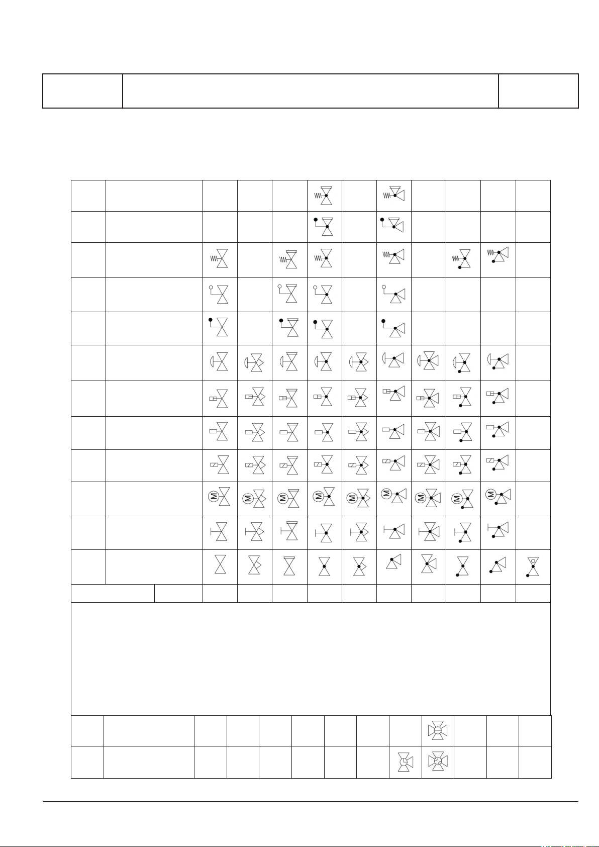
Basic symbols for piping
2237 Spring operated safety
valve
2238 Mass operated Safety
valve
2228 Spring actuator
2284 Float actuator
2229 Mass
2231 Membrane actuator
Symbols for piping
I 00 25 0
L27/38S, L16/24, L16/24S, L21/31, L21/31S, L23/30H, L23/30S, L23/30DF,
L28/32H, L28/32S, V28/32H, V28/32S, L27/38, L28/32DF
2230 Piston actuator
2232 Fluid actuator
2223 Solenoid actuator
2234 Electric motor actuator
2235 Hand operated
584: Valve general
585: Valve with continuous regulation
593: Valve with safety function
588:Straight-way valve
592: Straight-way valve with continuous regulation
590:Angle valve
591: Three-way valve
604: Straight-way non return valve
605: Angle non-return valve
579: Non-return valve, ball type
Basic Symbol
I - bored
Valves 584 585 593 588 592 590 591 604 605 579
L - bored
2015.11.17
Page 28
MAN Diesel & Turbo
I 00 25 0
Symbols for piping
L27/38S, L16/24, L16/24S, L21/31, L21/31S, L23/30H, L23/30S, L23/30DF,
L28/32H, L28/32S, V28/32H, V28/32S, L27/38, L28/32DF
T - bored
2237 Spring operated
safety valve
2238 Mass operated
Safety valve
2228 Spring actuator
2284 Float actuator
2229 Mass
2231 Membrane actuator
2230 Piston actuator
2232 Fluid actuator
1655279-1.1
Page 8 (10)
2223 Solenoid actuator
2234 Electric motor actua-
tor
2235 Hand operated
594: Straight-way reduction valve
595: Angle reduction valve
586: Gate valve
587: Gate valve with continuous regulation
599: Straight-way cock
600: Angle cock
601: Three-way cock
602: Four-way cock
607: Butterfly valve
608: Butterfly valve with continuous regulation
606: Non-return valve, flap type
Miscellaneous
Basic Symbol
Valves 594 595 586 587 599 600 601 602 607 608 606
No Symbol Symbol designation No Symbol Symbol designation
972 Pipe threaded connection
582 Funnel xxx Blind
581 Atomizer
Tanks
2015.11.17
Page 29
MAN Diesel & Turbo
1655279-1.1
Page 9 (10)
Symbols for piping
L27/38S, L16/24, L16/24S, L21/31, L21/31S, L23/30H, L23/30S, L23/30DF,
L28/32H, L28/32S, V28/32H, V28/32S, L27/38, L28/32DF
583 Air venting 631 Tank with domed ends
6.25 Air venting to the outside 771 Tank with conical ends
299 Normal opening/ closing speed yyy Electrical insert heater
300 Quick opening/ closing speed
613 Orifice with diffuser 8.03 Electrical preheater
612 Orifice 8.08 Heat exchanger
611 Sight glass 792 Nest of pipes with bends
615 Silencer 798 Plate heat exchanger
617 Berst membrane
Heat exchanger
Separators
I 00 25 0
629 Condensate relief 761 Separator
580 Reducer 764 Disc separator
589 Measuring point for thermo element
1298 Air relief valve 669 Air filter
Couplings/ Flanges
167 Coupling
955 Flanged connection 16.03 Cooling tower
971 Clamped connection 16.06 Radiator cooler
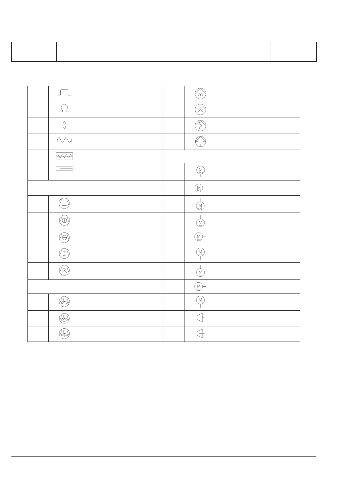
No Symbol Symbol designation No Symbol Symbol designation
Chimney Pumps
838 Chimney 708 Centrifugal pump
Filters
671 Fluid filter
Coolers
Expansion joints
2285 Expansion bellow 704 Piston pump - radial
4.1 Expansion pipe 700 Membrane pump
697 Piston pump
2015.11.17
Page 30
MAN Diesel & Turbo
I 00 25 0
Symbols for piping
L27/38S, L16/24, L16/24S, L21/31, L21/31S, L23/30H, L23/30S, L23/30DF,
L28/32H, L28/32S, V28/32H, V28/32S, L27/38, L28/32DF
4.1.1.1 Loop expansion joint 702 Gear pump
4.1.1.2 Lyra expansion joint 705 Screw pump
4.1.1.3 Lens expansion joint 706 Mono pump
4.1.1.4 Expansion bellow 703 Hand vane pump
4.1.1.5 Steel tube
4.1.1.6 Expansion joint with gland 13.14 Electrical motor AC
Compressors
716 Piston compressor 13.14 Electrical motor AC
Motors
13.14 Electrical motor AC
1655279-1.1
Page 10 (10)
725 Turbo axial compressor 13.15 Electrical motor DC
726 Turbo dial compressor 13.15 Electrical motor DC
720 Roots compressor 13.15 Electrical motor DC
722 Screw compressors 13.15 Electrical motor DC
Ventilators
637 Fan general 13.15 Electrical motor DC
638 Fan - radial 632 Turbine
639 Fan - axial 633 Piston engine
13.15 Electrical motor DC
2015.11.17
Page 31

MAN Diesel & Turbo
D 10 General
information
Page 1 (1)
D 10 General information
2018-04-13 - en
Page 32

Page 33

MAN Diesel & Turbo
1689471-7.4
Page 1 (2)
Capacities
5L27/38: 300 kW/cyl., 720 rpm,
6-9L27/38: 330 kW/cyl., 720 rpm
Engine output
Speed
Heat to be dissipated
Cooling water cylinder
Charge air cooler; cooling water HT
Charge air cooler; cooling water LT
Lubricating oil cooler
Heat radiation engine
Flow rates
4)
Internal (inside engine)
HT circuit (cylinder + charge air cooler HT stage)
LT circuit (lube oil + charge air cooler LT stage)
Lubrication oil
External (from engine to system)
HT water flow (at 40°C inlet)
LT water flow (at 38°C inlet)
Air data
Temperature of charge air at charge air cooler outlet
Air flow rate
Charge air pressure
Air required to dissipate heat radiation (eng.)
(t2-t1= 10°C)
Exhaust gas data
Volume flow (temperature turbocharger outlet)
Mass flow
Temperature at turbine outlet
Heat content (190°C)
Permissible exhaust back pressure
Permissible exhaust back pressure (SCR)
Pumps
External pumps
Diesel oil pump
Fuel oil supply pump
Fuel oil circulating pump
Starting air data
Air consumption per start,
incl. air for jet assist (IR/TDI)
3)
6)
8)
(5 bar at fuel oil inlet A1)
(4 bar discharge pressure)
9)
(8 bar at fuel oil inlet A1)
List of capacities
5 6 7 8 9
kW
rpm
kW
kW
kW
kW
kW
m3/h
m3/h
m3/h
m3/h
m3/h
°C
m3/h
kg/kWh
bar
m3/h
m3/h
t/h
°C
kW
mbar
mbar
m3/h
m3/h
m3/h
Nm
1500
720
256
466
178
224
63
58
58
64
16
58
50
5)
9137
6.67
4.01
20414
7)
19203
10.3
376
575
< 30
< 50
1.06
0.51
1.06
3
2.5 2.9 3.3 3.8 4.3
1980
720
330
594
216
279
83
58
58
64
20.2
58
53
12061
6.67
4.01
26895
25348
13.6
376
759
< 30
< 50
1.40
0.67
1.40
2310
720
385
675
242
325
97
58
58
92
23
58
55
14071
6.67
4.01
31431
29572
15.9
376
886
< 30
< 50
1.63
0.79
1.63
2640
720
440
750
268
372
111
58
58
92
25.5
58
56
16082
6.67
4.01
35968
33797
18.1
376
1012
< 30
< 50
1.87
0.90
1.87
D 10 05 0
L27/38S, L27/38
2970
720
495
820
297
418
125
58
58
92
28
58
57
18092
6.67
4.01
40504
38021
20.4
376
1139
< 30
< 50
2.10
1.01
2.10
2017.03.03 - 330 kW, 720 rpm
Page 34

MAN Diesel & Turbo
D 10 05 0
L27/38S, L27/38
Conditions
Reference condition : Tropic
Air temperature
LT water temperature inlet engine (from system)
Air pressure
Relative humidity
Temperature basis:
Set point HT cooling water engine outlet
Set point LT cooling water engine outlet
Set point lubrication oil inlet engine
Remarks to capacities
1)
HT cooling water flows first through HT stage charge air cooler, then through water jacket and cylinder head, water
temperature outlet engine regulated by mechanical thermostat.
2)
LT cooling water flows first through LT stage charge air cooler, then through lube oil cooler, water temperature
outlet engine regulated by mechanical thermostat.
3)
Tolerance: + 10% for rating coolers, - 15% for heat recovery.
4)
Basic values for layout of the coolers.
5)
Under above mentioned reference conditions.
6)
Tolerance: quantity +/- 5%, temperature +/- 20°C.
7)
Under below mentioned temperature at turbine outlet and pressure according above mentioned reference conditions.
8)
Tolerance of the pumps' delivery capacities must be considered by the manufactures.
9)
In order to ensure sufficient flow through the engine fuel system the capacity of the fuel oil circulation pumps must
be minimum 3 times the full load consumption of the installed engines
List of capacities
°C
°C
bar
%
1)
2)
°C
°C
°C
1689471-7.4
Page 2 (2)
45
38
1
50
79°C nominal
(Range of mech. thermostatic element 77-85°C)
35°C nominal
(Range of mech. thermostatic element 29-41°C)
66°C nominal
(Range of mech. thermostatic element 63-72°C)
High temperature alarms can occur for some
engine types running 100% MCR with SCR catalyst (50 mbar exhaust back pressure) and tropical condition (ambient air 45°C & LT-water
38°C).
2017.03.03 - 330 kW, 720 rpm
Page 35

MAN Diesel & Turbo
1689472-9.4
Page 1 (2)
Capacities
5L27/38: 320 kW/cyl., 750 rpm,
6-9L27/38: 330 kW/cyl., 750 rpm
Engine output
Speed
Heat to be dissipated
Cooling water cylinder
Charge air cooler; cooling water HT
Charge air cooler; cooling water LT
Lubricating oil cooler
Heat radiation engine
Flow rates
4)
Internal (inside engine)
HT circuit (cylinder + charge air cooler HT stage)
LT circuit (lube oil + charge air cooler LT stage)
Lubrication oil
External (from engine to system)
HT water flow (at 40°C inlet)
LT water flow (at 38°C inlet)
Air data
Temperature of charge air at charge air cooler outlet
Air flow rate
Charge air pressure
Air required to dissipate heat radiation (eng.)
(t2-t1= 10°C)
Exhaust gas data
Volume flow (temperature turbocharger outlet)
Mass flow
Temperature at turbine outlet
Heat content (190°C)
Permissible exhaust back pressure
Permissible exhaust back pressure (SCR)
Pumps
External pumps
Diesel oil pump
Fuel oil supply pump
Fuel oil circulating pump
Starting air data
Air consumption per start,
incl. air for jet assist (IR/TDI)
3)
6)
8)
(5 bar at fuel oil inlet A1)
(4 bar discharge pressure)
9)
(8 bar at fuel oil inlet A1)
List of capacities
5 6 7 8 9
kW
rpm
kW
kW
kW
kW
kW
m3/h
m3/h
m3/h
m3/h
m3/h
°C
m3/h
kg/kWh
bar
m3/h
m3/h
t/h
°C
kW
mbar
mbar
m3/h
m3/h
m3/h
Nm
1600
750
263
488
194
230
67
69
69
66
16.8
69
51
5)
9951
6.81
4.04
21710
7)
20546
11.2
365
589
< 30
< 50
1.13
0.54
1.13
3
2.5 2.9 3.3 3.8 4.3
1980
750
330
587
225
279
83
69
69
66
20.3
69
53
12314
6.81
4.04
26895
25426
13.9
365
729
< 30
< 50
1.40
0.67
1.40
2310
750
385
666
252
325
97
69
69
96
23
69
55
14367
6.81
4.04
31431
29664
16.2
365
850
< 30
< 50
1.63
0.79
1.63
2640
750
440
741
280
372
111
69
69
96
25.7
69
56
16419
6.81
4.04
35968
33901
18.5
365
972
< 30
< 50
1.87
0.90
1.87
D 10 05 0
L27/38S, L27/38
2970
750
495
811
307
418
125
69
69
96
28.2
69
57
18472
6.81
4.04
40504
38139
20.8
365
1093
< 30
< 50
2.10
1.01
2.10
2017.03.03 - 330 kW, 750 rpm
Page 36

MAN Diesel & Turbo
D 10 05 0
L27/38S, L27/38
Conditions
Reference condition : Tropic
Air temperature
LT water temperature inlet engine (from system)
Air pressure
Relative humidity
Temperature basis:
Set point HT cooling water engine outlet
Set point LT cooling water engine outlet
Set point lubrication oil inlet engine
Remarks to capacities
1)
HT cooling water flows first through HT stage charge air cooler, then through water jacket and cylinder head, water
temperature outlet engine regulated by mechanical thermostat.
2)
LT cooling water flows first through LT stage charge air cooler, then through lube oil cooler, water temperature
outlet engine regulated by mechanical thermostat.
3)
Tolerance: + 10% for rating coolers, - 15% for heat recovery.
4)
Basic values for layout of the coolers.
5)
Under above mentioned reference conditions.
6)
Tolerance: quantity +/- 5%, temperature +/- 20°C.
7)
Under below mentioned temperature at turbine outlet and pressure according above mentioned reference conditions.
8)
Tolerance of the pumps' delivery capacities must be considered by the manufactures.
9)
In order to ensure sufficient flow through the engine fuel system the capacity of the fuel oil circulation pumps must
be minimum 3 times the full load consumption of the installed engines
List of capacities
°C
°C
bar
%
1)
2)
°C
°C
°C
1689472-9.4
Page 2 (2)
45
38
1
50
79°C nominal
(Range of mech. thermostatic element 77-85°C)
35°C nominal
(Range of mech. thermostatic element 29-41°C)
66°C nominal
(Range of mech. thermostatic element 63-72°C)
High temperature alarms can occur for some
engine types running 100% MCR with SCR catalyst (50 mbar exhaust back pressure) and tropical condition (ambient air 45°C & LT-water
38°C).
2017.03.03 - 330 kW, 750 rpm
Page 37
MAN Diesel & Turbo
3700395-8.3
Page 1 (2)
GenSet
Vibration limits and measurements
D 10 24 0
L23/30DF, L28/32S-DF, L28/32S, L27/38S, L23/30S, L21/31S, L16/24S, L28/32DF,
V28/32H, V28/32S, L16/24, L21/31, L23/30H, L27/38, L28/32H
Measurement
point
1 TC fore 18
2 Governor/TC
3 Front support 18
4 Aft support 18
Engine: VDI 2063T
Alternator: ISO 8528-9, DIN 6280-11
Note: All measurements are specified as mm/s r.m.s.
Description Limit Measure-
ment
point
5 Aft alternator
18
aft
6 Alternator
7 Intermediate
8 Alternator foot See
Date Running
Hours
Description Limit Measure-
ment
point
18
25
18
bearing
cooler
bearing
below *
* Alternator
P ≤ 1250 kVA 20 24
P >1250 kVA 18 22
Value 1 or 2 are depending on alternator make
Load
%
100
1 2 3 4 5 6 7 8 9 10 11 12
Vertical (z)
Description Limit
9 Alternator foot See
below *
10 Automation box
A-side
11 Automation box
B-side
12 T&P panel 25
Value 1 Value 2
25
25
100
100
Crosswise (y)
Longitudinal (x)
2017.12.14
Page 38
MAN Diesel & Turbo
D 10 24 0
Vibration limits and measurements
L23/30DF, L28/32S-DF, L28/32S, L27/38S, L23/30S, L21/31S, L16/24S, L28/32DF,
V28/32H, V28/32S, L16/24, L21/31, L23/30H, L27/38, L28/32H
Turbocharger
Vibration acceleration measuring point, see the project guide for turbocharger.
Turbocharger type
f (Hz) mm/s g mm/s g mm/s g mm/s g mm/s g mm/s g
Meas.
pt (1)
Recommendation
Meas.
pt (2+3)
Contact engine builder
Meas.
pt (4)
Meas.
pt (1)
Meas.
pt (2+3)
Meas.
pt (4)
3700395-8.3
Page 2 (2)
TCR10
TCR12
NR12
TCR14
NR14, NR15, NR17 2.0 1.6 2.0 4.5 2.2 4.0
TCR16
NR20
TCR18
NR20, NR24 1.4 1.1 1.4 3.2 1.6 2.9
TCR20
NR24, NR26 1.2 0.9 1.2 2.6 1.3 2.3
TCR22 0.9 0.7 0.9 1.9 1.0 1.7
3-300 45
2.9
2.6 2.0 2.6 5.8 2.9 5.2
1.7 1.4 1.7 3.8 1.9 3.5
35
2.2
45
2.9
100
6.4
50
3.2
90
Turbocharger vibration limit values - measuring point
Date Running
Hours
Shop test
Load
%
100
100
1 2 3 4 5 6 7 8 9 10 11 12
Vertical (z)
Crosswise (y)
5.8
100
Longitudinal (x)
2017.12.14
Page 39

MAN Diesel & Turbo
1609510-3.5
Page 1 (1)
Description of sound measurements
L28/32S, L23/30DF, L28/32S-DF, L27/38S, L23/30S, L21/31S, L16/24S, L28/32DF,
V28/32H, V28/32S, L16/24, L21/31, L23/30H, L27/38, L28/32H
General
Purpose
This should be seen as an easily comprehensible
sound analysis of MAN GenSets. These measurements can be used in the project phase as a basis
for decisions concerning damping and isolation in
buildings, engine rooms and around exhaust systems.
Measuring equipment
All measurements have been made with Precision
Sound Level Meters according to standard IEC
Publication 651or 804, type 1 – with 1/1 or 1/3
octave filters according to standard IEC Publication
225. Used sound calibrators are according to
standard IEC Publication 942, class 1.
Definitions
Sound Pressure Level: LP = 20 x log P/P0 [dB ]
D 10 25 0
Sound measuring "on-site"
The Sound Power Level can be directly applied to
on-site conditions. It does not, however, necessarily
result in the same Sound Pressure Level as measured on test bed.
Normally the Sound Pressure Level on-site is 3-5
dB higher than the given surface Sound Pressure
Level (Lpf) measured at test bed. However, it
depends strongly on the acoustical properties of the
actual engine room.
Standards
Determination of Sound Power from Sound Pressure measurements will normally be carried out
according to:
ISO 3744 (Measuring method, instruments, background noise, no of microphone positions etc) and
ISO 3746 (Accuracy due to criterion for suitability of
test environment, K2>2 dB).
where P is the RMS value of sound pressure in pascals, and P0 is 20 μPa for measurement in air.
Sound Power Level: LW = 10 x log P/P0 [dB]
where P is the RMS value of sound power in watts,
and P0 is 1 pW.
Measuring conditions
All measurements are carried out in one of MAN
Diesel & Turbo's test bed facilities.
During measurements, the exhaust gas is led outside the test bed through a silencer. The GenSet is
placed on a resilient bed with generator and engine
on a common base frame.
Sound Power is normally determined from Sound
Pressure measurements.
New measurement of exhaust sound is carried out
at the test bed, unsilenced, directly after turbocharger, with a probe microphone inside the
exhaust pipe.
Previously used method for measuring exhaust
sound are DS/ISO 2923 and DIN 45635, here is
measured on unsilenced exhaust sound, one meter
from the opening of the exhaust pipe, see fig.1.
Figure 1: .
2016.02.22
Page 40

Page 41

MAN Diesel & Turbo
1671754-6.2
Page 1 (1)
Description of structure-borne noise
L28/32S, L23/30DF, L28/32S-DF, L27/38S, L23/30S, L21/31S, L16/24S, L28/32DF,
V28/32H, V28/32S, L16/24, L21/31, L23/30H, L27/38, L28/32H
Introduction
This paper describes typical structure-borne noise
levels from standard resiliently mounted MAN GenSets. The levels can be used in the project phase
as a reasonable basis for decisions concerning
damping and insulation in buildings, engine rooms
and surroundings in order to avoid noise and vibration problems.
References
References and guidelines according to ISO 9611
and ISO 11689.
Operating condition
Levels are valid for standard resilient mounted GenSets on flexible rubber support of 55° sh (A) on relatively stiff and well-supported foundations.
D 10 25 0
Frequency range
The levels are valid in the frequency range 31.5 Hz
to 4 kHz.
Figure 1: Structure-borne noise on resiliently mounted GenSets
2016.02.22
Page 42

Page 43

MAN Diesel & Turbo
1655210-7.3
Page 1 (2)
Exhaust gas components
L23/30DF, L28/32S-DF, V28/32S, V28/32H, L28/32S, L27/38S, L23/30S, L21/31S,
L16/24S, L28/32DF, L16/24, L21/31, L23/30H, L27/38, L28/32H
Exhaust gas components of medium
speed four-stroke diesel engines
The exhaust gas is composed of numerous constituents which are formed either from the combustion
air, the fuel and lube oil used or which are chemical
reaction products formed during the combustion
process. Only some of these are to be considered
as harmful substances.
For the typical exhaust gas composition of a MAN
Diesel & Turbo four-stroke engine without any
exhaust gas treatment devices, please see tables
below (only for guidance). All engines produced currently fulfil IMO Tier II.
Carbon dioxide CO
Carbon dioxide (CO2) is a product of combustion of
all fossil fuels.
Among all internal combustion engines the diesel
engine has the lowest specific CO2 emission based
on the same fuel quality, due to its superior efficiency.
2
D 10 28 0
Hydrocarbons HC
The hydrocarbons (HC) contained in the exhaust
gas are composed of a multitude of various organic
compounds as a result of incomplete combustion.
Due to the efficient combustion process, the HC
content of exhaust gas of MAN Diesel & Turbo fourstroke diesel engines is at a very low level.
Particulate matter PM
Particulate matter (PM) consists of soot (elemental
carbon) and ash.
Sulphur oxides SO
Sulphur oxides (SOX) are formed by the combustion
of the sulphur contained in the fuel.
Among all propulsion systems the diesel process
results in the lowest specific SOx emission based
on the same fuel quality, due to its superior efficiency.
Nitrogen oxides NO
The high temperatures prevailing in the combustion
chamber of an internal combustion engine causes
the chemical reaction of nitrogen (contained in the
combustion air as well as in some fuel grades) and
oxygen (contained in the combustion air) to nitrogen
oxides (NOX).
X
X
Carbon monoxide CO
Carbon monoxide (CO) is formed during incomplete
combustion.
In MAN Diesel & Turbo four-stroke diesel engines,
optimisation of mixture formation and turbocharging
process successfully reduces the CO content of the
exhaust gas to a very low level.
2016.02.22
Page 44

MAN Diesel & Turbo
D 10 28 0
Exhaust gas components
L23/30DF, L28/32S-DF, V28/32S, V28/32H, L28/32S, L27/38S, L23/30S, L21/31S,
L16/24S, L28/32DF, L16/24, L21/31, L23/30H, L27/38, L28/32H
Main exhaust gas constituents
Nitrogen N
Oxygen O
Carbon dioxide CO
2
2
2
Steam H2O 5.9 - 8.6 260 - 370
Inert gases Ar, Ne, He ... 0.9 75
Total > 99.75 7,000
Additional gaseous exhaust gas constituents considered as pollutants
Sulphur oxides SO
Nitrogen oxides NO
Carbon monoxide CO
Hydrocarbons HC
1)
X
2)
X
3)
4)
Total < 0.25 26
approx. [% by volume] approx. [g/kWh]
74.0 - 76.0 5,020 - 5,160
11.6 - 13.2 900 - 1,030
5.2 - 5.8 560 - 620
approx. [% by volume] approx. [g/kWh]
0.07 10.0
0.07 - 0.10 8.0 - 10.0
0.006 - 0.011 0.4 - 0.8
0.01 - 0.04 0.4 - 1.2
1655210-7.3
Page 2 (2)
Additional suspended exhaust gas
constituents, PM
5)
approx. [mg/Nm3] approx. [g/kWh]
operating on operating on
Soot (elemental carbon)
6)
MGO
8)
50 50 0.3 0.3
HFO
7)
MGO
6)
HFO
Fuel ash 4 40 0.03 0.25
Lube oil ash 3 8 0.02 0.04
Note!
At rated power and without exhaust gas treatment.
1)
SOX, according to ISO-8178 or US EPA method 6C, with a sulphur content in the fuel oil of 2.5% by weight.
2)
NOX according to ISO-8178 or US EPA method 7E, total NOX emission calculated as NO2.
3)
CO according to ISO-8178 or US EPA method 10.
4)
HC according to ISO-8178 or US EPA method 25A.
5)
PM according to VDI-2066, EN-13284, ISO-9096 or US EPA method 17; in-stack filtration.
6)
Marine gas oil DM-A grade with an ash content of the fuel oil of 0.01% and an ash content of the lube oil of 1.5%.
7)
Heavy fuel oil RM-B grade with an ash content of the fuel oil of 0.1% and an ash content of the lube oil of 4.0%.
8)
Pure soot, without ash or any other particle-borne constituents.
7)
2016.02.22
Page 45

MAN Diesel & Turbo
3700044-8.0
Page 1 (1)
Emission limits Worldbank II
L28/32S, L23/30S, L16/24S, L21/31S, L27/38S, V28/32S
Emission limits
In general the engine is designed to fulfil the
emission limits according Worldbank II
(2007/2008) for plants ≤ 300 MWth and nondegraded airshed.
SOx and PM emissions are mainly influenced by the
fuel specification. The sulphur and the ash content
must be limited accordingly. The NOx emission is
influenced by the ambient conditions, fuel specifica-
tions and operating conditions of the engine.
Please contact MAN Diesel & Turbo at an early
stage for project specific emission calculations
(contact your sales representative).
Needed adaptions of the engine parameters to fulfil
project specific emission limits may in minor extent
affect the fuel oil consumption.
Worldbank II 2007/2008, only for liquid fuel (L16/24, L21/31, L27/38, V28/32S)
Bore size < 400
3 MWth < x ≤ 50 MW
50 MWth < x ≤ 300 MWthNon-degraded airshed:
NOx ≤ 1460 mg/Nm3 at
th
15% O
2
(NOx ≤ 1600 mg/Nm3 at
15% O2 to maintain higher
effic.)
NOx ≤ 1460 mg/Nm3 at
15% O
2
SOx : max. 1,5% sulphur in fuel
(up 3% exceptionell)
SOx ≤ 1170 mg/Nm3 at 15% O
or max. 2% sulphur in fuel
D 10 28 0
PM ≤ 50 mg/Nm3 at 15% O
(100 mg/Nm3 for econ. rea-
sons)
PM ≤ 50 mg/Nm3 at 15% O
2
2
2
Degraded airshed:
NOx ≤ 400 mg/Nm3 at
15% O
300 MWth < x Non-degraded airshed:
NOx ≤ 740 mg/Nm3 at
15% O
Degraded airshed:
NOx ≤ 400 mg/Nm3 at
15% O
SOx : max. 0.5% sulphur in fuel
2
SOx ≤ 585 mg/Nm3 at 15% O
2
or max. 2% sulphur in fuel
SOx : max. 0.2% sulphur in fuel
2
PM ≤ 30 mg/Nm3 at 15% O
PM ≤ 50 mg/Nm3 at 15% O
2
PM ≤ 30 mg/Nm3 at 15% O
2
2
2
2015.11.16
Page 46

Page 47

MAN Diesel & Turbo
1687148-5.2
Page 1 (1)
Moment of inertia
GenSet
Eng. type Moments of inertia Flywheel
Number of
cylinders
n = 720 rpm
5L27/38
6L27/38
7L27/38
8L27/38
9L27/38
n = 750 rpm
5L27/38
6L27/38
7L27/38
8L27/38
9L27/38
Continuous
rating
kW Kgm
1500
2100
2450
2800
3150
1600
2100
2450
2800
3150
Moments
required total
J
min
2
691
968
1129
1290
1451
679
892
1040
1189
1338
Engine +
damper
2
Kgm
207
264
291
353**)
381**)
207
264
291
353**)
381**)
Moments of
inertia
2
Kgm
403
403
403
403
403
403
403
403
403
403
D 10 30 0
L27/38S, L27/38
Mass Required
moment of
inertia after
flywheel *)
kg Kgm
1451
1451
1451
1451
1451
1451
1451
1451
1451
1451
2
81
301
435
534
667
69
225
346
433
554
*) Required moment of inertia after flywheel is based on 403 Kgm2 flywheel, and the most common damper.
The calucation is based on 42% engine acceleration.
Larger flywheel means lower alternator inertia demand, as total GenSet inertia is the final demand.
Selection of bigger flywheel for having lower alternator inertia demand, have to be approved by a torsional
vibration calculation.
The following flywheels are available:
J
J
J
=
=
=
403 Kgm
570 Kgm
801 Kgm
2
2
2
**) Incl. flexible coupling for two bearing alternator.
2015.11.27
Page 48

Page 49

MAN Diesel & Turbo
1699985-1.1
Page 1 (1)
V28/32S, V28/32H, L28/32S, L27/38S, L23/30DF, L23/30S, L16/24S, L21/31S,
Green Passport
In 2009 IMO adopted the „Hong Kong International
Convention for the Safe and Environmentally Sound
Recycling of Ships, 2009“.
Until this convention enters into force the recommendatory guidelines “Resolution A.962(23)” (adopted 2003) apply. This resolution has been implemented by some classification societies as “Green
Passport”.
MAN Diesel & Turbo is able to provide a list of hazardous materials complying with the requirements
of the IMO Convention. This list is accepted by classification societies as a material declaration for
“Green Passport”.
This material declaration can be provided on
request.
Green Passport
D 10 33 0
L28/32DF, L16/24, L21/31, L23/30H, L27/38, L28/32H
2015.11.26
Page 50

Page 51
MAN Diesel & Turbo
3700340-7.1
Page 1 (2)
Overhaul recommendation, Maintenance and Expected
D 10 35 0
life time
L27/38S, L27/38
* After starting up and before loading engine.
** Time between overhauls: It is a precondition for the validity of the values stated above, that the engine is oper-
ated in accordance with our instructions and recommendations for cleaning of fuel and lub. oil and original spare
parts are used.
2014.05.09 - MGO/MDO, Tier II, Stationary island mode 1)
In the Project Guide for GenSet, see Lub. Oil treatment, in section B 12 00 0 and Fuel oil specification in section
B 11 00 0 and section 14 000 for Propulsion.
In the Instruction Manual for GenSet and L21/31 Propulsion, see Lub. Oil treatment and Fuel oil specification in
section 504/604. For Propulsion L27/38, L23/30A, L28/32A see section 1.00.
Page 52

MAN Diesel & Turbo
D 10 35 0
L27/38S, L27/38
1) Island mode, max. 75 % average load.
2) Parallel running with public grid, up to 100 % load.
3) See working card for fuel injection valve in the instruction manual, section 514/614 for GenSet and section 1.20.
4) Time can be adjusted acc. to performance observations.
Note: Time between overhaul for Crude oil is equal to HFO
Time between overhaul for Biofuel is equal to MDO, except for fuel equipment case by case, depending on TAN
number
Overhaul recommendation, Maintenance and Expected
life time
3700340-7.1
Page 2 (2)
2014.05.09 - MGO/MDO, Tier II, Stationary island mode 1)
Page 53

MAN Diesel & Turbo
3700341-9.1
Page 1 (2)
Overhaul recommendation, Maintenance and Expected
D 10 35 0
life time
L27/38S, L27/38
* After starting up and before loading engine.
** Time between overhauls: It is a precondition for the validity of the values stated above, that the engine is oper-
ated in accordance with our instructions and recommendations for cleaning of fuel and lub. oil and original spare
parts are used.
2014.05.09 - HFO, Tier II, Stationary island mode 1)
In the Project Guide for GenSet, see Lub. Oil treatment, in section B 12 00 0 and Fuel oil specification in section
B 11 00 0 and section 14 000 for Propulsion.
In the Instruction Manual for GenSet and L21/31 Propulsion, see Lub. Oil treatment and Fuel oil specification in
section 504/604. For Propulsion L27/38, L23/30A, L28/32A see section 1.00.
1) Island mode, max. 75 % average load.
Page 54

MAN Diesel & Turbo
D 10 35 0
L27/38S, L27/38
2) Parallel running with public grid, up to 100 % load.
3) See working card for fuel injection valve in the instruction manual, section 514/614 for GenSet and section 1.20.
4) Time can be adjusted acc. to performance observations.
Note: Time between overhaul for Crude oil is equal to HFO
Time between overhaul for Biofuel is equal to MDO, except for fuel equipment case by case, depending on TAN
number
Overhaul recommendation, Maintenance and Expected
life time
3700341-9.1
Page 2 (2)
2014.05.09 - HFO, Tier II, Stationary island mode 1)
Page 55

MAN Diesel & Turbo
3700342-0.1
Page 1 (2)
Overhaul recommendation, Maintenance and Expected
D 10 35 0
life time
L27/38S
* After starting up and before loading engine.
** Time between overhauls: It is a precondition for the validity of the values stated above, that the engine is oper-
ated in accordance with our instructions and recommendations for cleaning of fuel and lub. oil and original spare
parts are used.
2014.08.12 - MGO/MDO, stationary public grid
In the Project Guide for GenSet, see Lub. Oil treatment, in section B 12 00 0 and Fuel oil specification in section
B 11 00 0 and section 14 000 for Propulsion.
In the Instruction Manual for GenSet and L21/31 Propulsion, see Lub. Oil treatment and Fuel oil specification in
section 504/604. For Propulsion L27/38, L23/30A, L28/32A see section 1.00.
1) Island mode, max. 75 % average load.
Page 56

MAN Diesel & Turbo
D 10 35 0
L27/38S
Note: Time between overhaul for Crude oil is equal to HFO
Overhaul recommendation, Maintenance and Expected
life time
2) Parallel running with public grid, up to 100 % load.
3) See working card for fuel injection valve in the instruction manual, section 514/614 for GenSet and section 1.20.
4) Time can be adjusted acc. to performance observations.
Time between overhaul for Biofuel is equal to MDO, except for fuel equipment case by case, depending on TAN
number
3700342-0.1
Page 2 (2)
2014.08.12 - MGO/MDO, stationary public grid
Page 57

MAN Diesel & Turbo
3700343-2.1
Page 1 (2)
Overhaul recommendation, Maintenance and Expected
D 10 35 0
life time
L27/38S
* After starting up and before loading engine.
** Time between overhauls: It is a precondition for the validity of the values stated above, that the engine is oper-
ated in accordance with our instructions and recommendations for cleaning of fuel and lub. oil and original spare
parts are used.
2014.05.09 - HFO, Stationary public grid 2)
In the Project Guide for GenSet, see Lub. Oil treatment, in section B 12 00 0 and Fuel oil specification in section
B 11 00 0 and section 14 000 for Propulsion.
In the Instruction Manual for GenSet and L21/31 Propulsion, see Lub. Oil treatment and Fuel oil specification in
section 504/604. For Propulsion L27/38, L23/30A, L28/32A see section 1.00.
1) Island mode, max. 75 % average load.
Page 58

MAN Diesel & Turbo
D 10 35 0
L27/38S
Note: Time between overhaul for Crude oil is equal to HFO
Overhaul recommendation, Maintenance and Expected
life time
2) Parallel running with public grid, up to 100 % load.
3) See working card for fuel injection valve in the instruction manual, section 514/614 for GenSet and section 1.20.
4) Time can be adjusted acc. to performance observations.
Time between overhaul for Biofuel is equal to MDO, except for fuel equipment case by case, depending on TAN
number
3700343-2.1
Page 2 (2)
2014.05.09 - HFO, Stationary public grid 2)
Page 59

MAN Diesel & Turbo
B 10 Basic diesel
engine
Page 1 (1)
B 10 Basic diesel engine
2018-04-13 - en
Page 60

Page 61

MAN Diesel & Turbo
1689477-8.1
Page 1 (7)
General
The engine is a turbocharged, single-acting fourstroke diesel engine of the trunk piston type with a
cylinder bore of 270 mm and a stroke of 380 mm.
The crank shaft speed is 720 or 750 rpm.
The engine can be delivered as an in-line engine
with 5 to 9 cylinders.
For easy maintenance the cylinder unit consists of:
the cylinder head, water jacket, cylinder liner, piston
and connecting rod which can be removed as complete assemblies with possibility for maintenance by
recycling. This allows shoreside reconditioning work
which normally yields a longer time between major
overhauls.
The engine is designed for an unrestricted load profile on HFO, low emission, high reliability and simple
installation.
General description
Engine frame
The monobloc cast iron engine frame is designed to
be very rigid. All the components of the engine
frame are held under compression stress. The
frame is designed for an ideal flow of forces from
the cylinder head down to the crankshaft and gives
the outer shell low surface vibrations.
Two camshafts are located in the engine frame. The
valve camshaft is located on the exhaust side in a
very high position and the injection camshaft is
located on the service side of the engine.
The main bearings for the underslung crankshaft
are carried in heavy supports by tierods from the
intermediate frame floor, and are secured with the
bearing caps. These are provided with side guides
and held in place by means of studs with hydraulically tightened nuts. The main bearing is equipped
with replaceable shells which are fitted without
scraping.
On the sides of the frame there are covers for
access to the camshafts and crankcase. Some
covers are fitted with relief valves which will operate
if oil vapours in the crankcase are ignited (for
instance in the case of a hot bearing).
B 10 01 1
L27/38S, L27/38
Figure 1: Engine frame.
Base frame
The engine and alternator are mounted on a rigid
base frame. The alternator is considered as an integral part during engine design. The base frame,
which is flexibly mounted, acts as a lubricating oil
reservoir for the engine.
Cylinder liner
The cylinder liner is made of special centrifugal cast
iron and fitted in a bore in the engine frame. The
liner is clamped by the cylinder head and rests by
its flange on the water jacket.
2015.11.26
Page 62

MAN Diesel & Turbo
B 10 01 1
L27/38S, L27/38
General description
The cylinder head is tightened by means of 4 nuts
and 4 studs which are screwed into the engine
frame. The nuts are tightened by means of hydraulic
jacks.
The cylinder head has a screwed-on top cover. It
has two basic functions: oil sealing of the rocker
chamber and covering of the complete head top
face.
1689477-8.1
Page 2 (7)
Figure 2: Cylinder liner.
The liner can thus expand freely downwards when
heated during the running of the engine. The liner is
of the flange type and the height of the flange is
identical with the water cooled area which gives a
uniform temperature pattern over the entire liner
surface. The lower part of the liner is uncooled to
secure a sufficient margin for cold corrosion in the
bottom end. There is no water in the crankcase
area.
The gas sealing between liner and cylinder head
consists of an iron ring.
To reduce bore polishing and lube oil consumption
a slip-fit-type top land ring is arranged on the top
side of the liner.
Cylinder head
The cylinder head is of cast iron with an integrated
charge air receiver, made in one piece. It has a
bore-cooled thick walled bottom. It has a central
bore for the fuel injection valve and 4 valve cross
flow design, with high flow coefficient. Intensive
water cooling of the nozzle tip area made it possible
to omit direct nozzle cooling. The valve pattern is
turned about 20° to the axis and achieves a certain
intake swirl.
Figure 3: Cylinder head.
Air inlet and exhaust valves
The valve spindles are made of heat-resistant mate-
rial and the spindle seats are armoured with wel-
ded-on hard metal.
All valve spindles are fitted with valve rotators which
turn the spindles each time the valves are activated.
The turning of the spindles ensures even temperature levels on the valve discs and prevents deposits
on the seating surfaces.
The cylinder head is equipped with replaceable
valve seat rings. The exhaust valve seat rings are
water cooled in order to assure low valve temperatures.
The seat rings are made of heat-resistant steel. The
seating surfaces are hardened in order to minimize
wear and prevent dent marks.
2015.11.26
Page 63
MAN Diesel & Turbo
1689477-8.1
Page 3 (7)
Valve actuating gear
Drive of the push rod for the inlet and exhaust
valves is from the camshaft via inlet and exhaust
rocking levers supported on a joint pillow, with the
cam movements being transmitted via a follower.
The push rod movement is in the cylinder head
transmitted to short rockers, and from these to a
guided, spring-loaded yoke. This yoke operates two
equal valves each.
The pillow supporting the rocking levers (the rocking
lever casing) is bolted to the cylinder head.
Bearing bushes, ball pans and yokes are lubricated
by means of a fitting in the pillow.
Fuel injection system
The engine is provided with one fuel injection pump
unit, an injection valve, and a high pressure pipe for
each cylinder.
The injection pump unit is mounted on the engine
frame. The pump unit consists of a pump housing
embracing a roller guide, a centrally placed pump
barrel and a plunger. The pump is activated by the
fuel cam, and the volume injected is controlled by
turning the plunger.
The fuel injection valve is located in a valve sleeve in
the centre of the cylinder head. The opening of the
valve is controlled by the fuel oil pressure, and the
valve is closed by a spring.
The high pressure pipe which is led through a bore
in the cylinder head is surrounded by a shielding
tube.
The shielding tube also acts as a drain channel in
order to ensure any leakage from the fuel valve and
the high pressure pipe will be drained off.
The complete injection equipment including injection pumps and high pressure pipes is well
enclosed behind removable covers.
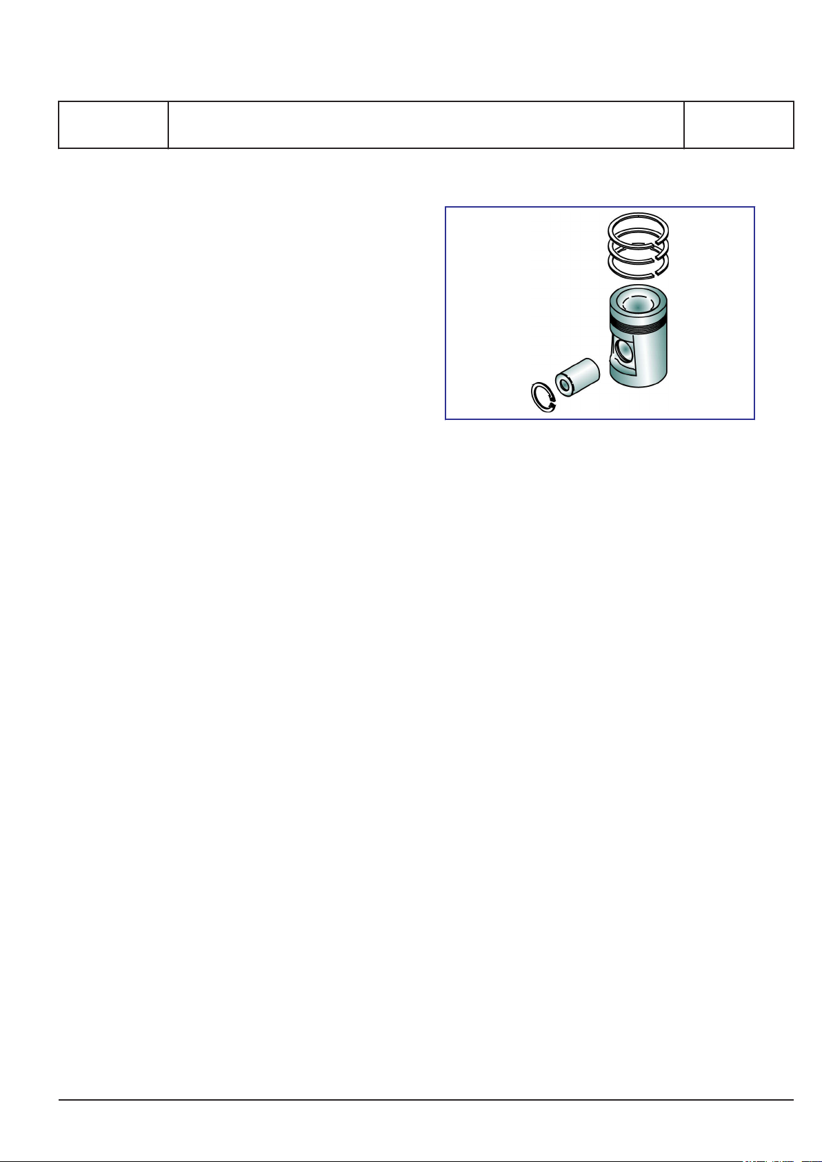
Piston
The piston, which is oil-cooled and of the composite type, has a body made of nodular cast iron and
a crown made of forged deformation resistant steel.
It is fitted with 2 compression rings and 1 oil scraper
ring in hardened ring grooves.
General description
Figure 4: Piston
By the use of compression rings with different barrelshaped profiles and chrome-plated running surfaces, the piston ring pack is optimized for maximum
sealing effect and minimum wear rate.
The piston has a cooling oil space close to the piston crown and the piston ring zone. The heat transfer, and thus the cooling effect, is based on the
shaker effect arising during the piston movement.
The cooling medium is oil from the engine's lubricating oil system.
Oil is supplied to the cooling oil space through
channels from the oil grooves in the piston pin
bosses. Oil is drained from the cooling oil space
through ducts situated diametrically to the inlet
channels.
The piston pin is fully floating and kept in position in
the axial direction by two circlips.
Connecting rod
The connecting rod is of the marine head type.
The joint is above the connecting rod bearing. This
means that the big-end bearing must not be
opened when pulling the piston. This is of advantage for the operational safety (no positional
changes/no new adaption), and this solution also
reduces the height dimension required for piston
assembly / removal.
Connecting rod and bearing body consist of CrMo
steel. They are die-forged products.
The bearing shells are identical to those of the
crankshaft bearing. Thin-walled bearing shells having an AISn running layer are used.
B 10 01 1
L27/38S, L27/38
2015.11.26
Page 64

MAN Diesel & Turbo
B 10 01 1
L27/38S, L27/38
The bearing caps and bearing blocks are bolted
together by waisted bolts.
General description
Camshaft and camshaft drive
The inlet and exhaust valves as well as the fuel
pumps of the engine are actuated by two cam-
shafts.
Due to the two-camshaft design an optimal adjustment of the gas exchange is possible without interrupting the fuel injection timing. It is also possible to
adjust the fuel injection without interrupting the gas
exchange.
The two camshafts are located in the engine frame.
On the exhaust side, in a very high position, the
valve camshaft is located to allow a short and stiff
valve train and to reduce moving masses.
1689477-8.1
Page 4 (7)
Figure 5: Connecting rod.
Crankshaft and main bearings
The crankshaft, which is a one-piece forging with
hardened bearing surfaces to achieve better wear
resistance, is suspended in underslung bearings.
The main bearings are of the trimetal type, which
are coated with a running layer. To attain a suitable
bearing pressure and vibration level the crankshaft
is provided with counterweights, which are attached
to the crankshaft by means of two hydraulic
screws.
At the flywheel end the crankshaft is fitted with a
gear wheel which, through two intermediate wheels,
drives the camshafts.
Also fitted here is a coupling flange for the connection of an alternator. At the opposite end (front end)
there is a gear wheel connection for lube oil and
water pumps.
Lubricating oil for the main bearings is supplied
through holes drilled in the engine frame. From the
main bearings the oil passes through bores in the
crankshaft to the big-end bearings and thence
through channels in the connecting rods to lubricate
the piston pins and cool the pistons.
Figure 6: Twin camshafts.
The injection camshaft is located at the service side
of the engine.
Both camshafts are designed as cylinder sections
and bearing sections in such a way that disassem-
bly of single cylinder sections is possible through
the side openings in the crankcase.
The two camshafts and the governor are driven by
the main gear train which is located at the flywheel
end of the engine. They rotate with a speed which
is half that of the crankshaft.
2015.11.26
Page 65
MAN Diesel & Turbo
1689477-8.1
Page 5 (7)
The camshafts are located in bearing bushes which
are fitted in bores in the engine frame; each bearing
is replaceable and locked in position in the engine
frame by means of a locking screw.
General description
B 10 01 1
L27/38S, L27/38
Figure 7: Front-end box.
The gear wheel for driving the camshaft as well as a
gear wheel connection for the governor drive are
screwed on to the aftmost section.
The lubricating oil pipes for the gear wheels are
equipped with nozzles which are adjusted to apply
the oil at the points where the gear wheels are in
mesh.
The components can be exchanged by means of
the clip on/clip off concept without removing any
pipes. This also means that all connections for the
engine, such as cooling water and fuel oil, are to be
connected at the front end of the engine to ensure
simple installation.
Governor
Front-end box
The front-end box is fastened to the front end of the
engine. It contains all pipes for cooling water and
lubricating oil systems and also components such
as pumps, filters, coolers and valves.
2015.11.26
The engine speed is controlled by a hydraulic or
electronic governor with hydraulic actuators.
Page 66

MAN Diesel & Turbo
B 10 01 1
L27/38S, L27/38
Safety and control system
The engine is equipped with MAN Diesel & Turbo’s
own design of safety and control system called
SaCoS
toring system” and “B 19 00 0 Communication from
the GenSet”.
Turbocharger system
The turbocharger system of the engine, which is a
constant pressure system, consists of an exhaust
gas receiver, a turbocharger, a charging air cooler
and a charging air receiver.
The turbine wheel of the turbocharger is driven by
the engine exhaust gas, and the turbine wheel
drives the turbocharger compressor, which is
mounted on the common shaft. The compressor
draws air from the engine room through the air filters.
The turbocharger forces the air through the charging air cooler to the charging air receiver. From the
charging air receiver the air flows to each cylinder
through the inlet valves.
The charging air cooler is a compact two-stage
tube-type cooler with a large cooling surface. The
high temperature water is passed through the first
stage of the charging air cooler and the low temperature water is passed through the second stage. At
each stage of the cooler the water is passed two
times through the cooler, the end covers being
designed with partitions which cause the cooling
water to turn.
The cooling water for the low temperature stages of
the charge air is controlled by the scavenging pressure to ensure sufficient scavenging temperature for
burning HFO. A water mist catcher can be adopted
after the air cooler as an option.
From the exhaust valves, the exhaust gas is led
through to the exhaust gas receiver where the pulsatory pressure from the individual cylinders is
equalized and passed on to the turbocharger as a
constant pressure, and further to the exhaust outlet
and silencer arrangement.
The exhaust gas receiver is made of pipe sections,
one for each cylinder, connected to each other by
means of compensators to prevent excessive stress
in the pipes due to heat expansion.
.
See “B 19 00 0 Safety, control and moni-
one
General description
To avoid excessive thermal loss and to ensure a
reasonably low surface temperature the exhaust
gas receiver is insulated.
Compressed air system
The engine is started by means of a built-on air
driven starter.
The compressed air system comprises a dirt
strainer, main starting valve and a pilot valve which
also acts as an emergency valve, making it possible
to start the engine in case of a power failure.
Lubricating oil system
All moving parts of the engine are lubricated with oil
circulating under pressure.
The lubricating oil pump is of the helical gear type.
A pressure control valve is built into the system. The
pressure control valve reduces the pressure before
the filter with a signal taken after the filter to ensure
constant oil pressure with dirty filters.
The pump draws the oil from the sump in the base
frame, and on the pressure side the oil passes
through the lubricating oil cooler and the full-flow
depth filter with a nominel fineness of 15 microns.
Both the oil pump, oil cooler and the oil filter are
placed in the front end box. The system can also be
equipped with a centrifugal filter.
Cooling is carried out by the low temperature cool-
ing water system and temperature regulation effec-
ted by a thermostatic 3-way valve on the oil side.
The engine is as standard equipped with an electri-
cally driven prelubricating pump.
Cooling water system
The cooling water system consists of a low temper-
ature system and a high temperature system.
Both the low and the high temperature systems are
cooled by fresh water.
Only a one string cooling water system to the
engine is required.
The water in the low temperature system passes
through the low temperature circulating pump
which drives the water through the second stage of
the charge air cooler and then through the lubricat-
ing oil cooler before it leaves the engine together
with the high temperature water.
1689477-8.1
Page 6 (7)
2015.11.26
Page 67

MAN Diesel & Turbo
1689477-8.1
Page 7 (7)
The high temperature cooling water system passes
through the high temperature circulating pump and
then through the first stage of the charge air cooler
before it enters the cooling water jacket and the cylinder head. Then the water leaves the engine with
the low temperature water.
Both the low and high temperature water leaves the
engine through separate three-way thermostatic
valves which control the water temperature.
It should be noted that there is no water in the
engine frame.
General description
Turning
The engine is equipped with a manual turning
device.
B 10 01 1
L27/38S, L27/38
Figure 8: Internal cooling water system.
Tools
The engine can be delivered with all necessary tools
for the overhaul of each specific plant. Most of the
tools can be arranged on steel plate panels.
2015.11.26
Page 68

Page 69
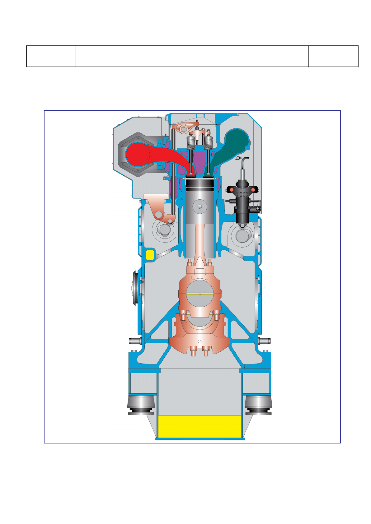
MAN Diesel & Turbo
1665740-7.3
Page 1 (1)
Cross section
Cross section
B 10 01 1
L27/38S, L27/38
2014.11.18
Page 70

Page 71

MAN Diesel & Turbo
3700157-5.1
Page 1 (1)
Main particulars
Main Particulars
Cycle : 4-stroke
Configuration : In-line
Cyl. nos available : 5 - 6 - 7 - 8 - 9
Power range : 1500 - 2970 kW (HFO/MDO)
Speed : 720 / 750 rpm
Bore : 270 mm
Stroke : 380 mm
Stroke/bore ratio : 1.4 : 1
Piston area per cyl. : 572.6 cm
swept volume per cyl. : 21.8 ltr
Compression ratio : 15.9 : 1
Turbocharging principle : Constant pressure system and intercooling
Fuel quality acceptance : HFO (up to 700 cSt/50º C, RMK700)
MDO (DMB) - MGO (DMA, DMZ)
according ISO8217-2010
Power lay-out
Speed rpm 720 750
Mean piston speed m/sec. 9.1 9.5
Mean effective pressure
5 cyl. engine (HFO/MDO)
6, 7, 8, 9 cyl. engine (HFO/MDO)
Max. combustion pressure
5 cyl. engine (HFO/MDO)
6, 7, 8, 9 cyl. engine (HFO/MDO)
Power per cylinder
5 cyl. engine (HFO/MDO)
6, 7, 8, 9 cyl. engine (HFO/MDO)
bar
bar
bar
bar
kW per cyl.
kW per cyl.
2
MCR version
23.0
25.3
190
200
300
330
B 10 01 1
L27/38S
23.5
24.3
190
200
320
330
2011.09.05 - WB1 - WB2 - GenSet
Page 72

Page 73
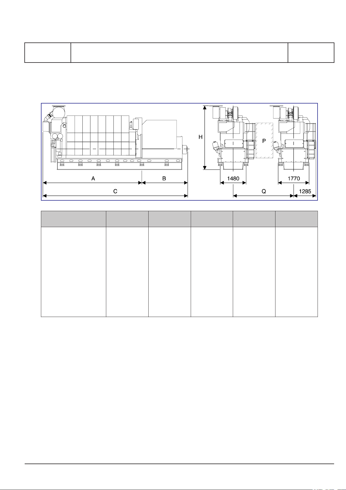
MAN Diesel & Turbo
1689493-3.1
Page 1 (1)
General
Dimensions and weights
B 10 01 1
L27/38S, L27/38
Cyl. no A (mm) * B (mm) * C (mm) H (mm) ** Dry weight
GenSet (t)
5 (720 mm)
5 (750 mm)
4346
4346
2486
2486
6832
6832
3712
3712
40.0
40.0
6 (720 mm)
6 (750 mm)
7 (720 mm)
7 (750 mm)
8 (720 mm)
8 (750 mm)
9 (720 mm)
9 (750 mm)
P
Free passage between the enginges, width 600 mm and height 2000 mm.
Q
Min. distance between engines: 2900 mm (without gallery) and 3100 mm (with gallery)
*
Depending on alternator
**
Weight included a standard alternator
4791
4791
5236
5236
5681
5681
6126
6126
2766
2766
2766
2766
2986
2986
2986
2986
7557
7557
8002
8002
8667
8667
9112
9112
3712
3712
3899
3899
3899
3899
3899
3899
All dimensions and masses are approximate, and subject to changes without prior notice.
44.5
44.5
50.4
50.4
58.2
58.2
64.7
64.7
2015.11.27 - TCR
Page 74

Page 75

MAN Diesel & Turbo
1679708-8.2
Page 1 (1)
Description
Centre of gravity
Engine type X - mm Y - mm Z - mm
5L27/38
1520
1475
0
B 10 01 1
L27/38S, L27/38
6L27/38
7L27/38
8L27/38
9L27/38
1805
2050
2390
2680
1480
1485
1490
1490
0
0
0
0
The values are based on water-cooled alternator,
make Hyundai. If another alternator is chosen, the
values will change.
2015.02.20
Page 76

Page 77

MAN Diesel & Turbo
1665770-6.6
Page 1 (4)
Dismantling height
Overhaul areas
B 10 01 1
L27/38S, L27/38
Figure 1: Dismantling height.
Description
Normal dismantling:
Cylinder unit
Low dismantlig:
Cover and liner separate
H
::For dismantling at the service side.
1
For dismantlig passing the alternator.
H
2
(with standard alternator, remaining cover not
removed.)
H1 (mm) H2 (mm)
4201
3891
4791
–
2015.11.27
Page 78

MAN Diesel & Turbo
B 10 01 1
L27/38S, L27/38
Overhaul areas
1665770-6.6
Page 2 (4)
* Overhaul with dismantled fuel injection pump/piping.
2015.11.27
Page 79

MAN Diesel & Turbo
1665770-6.6
Page 3 (4)
Low dismantling height
Overhaul areas
B 10 01 1
L27/38S, L27/38
Important! Extra dismantling height is required in
the areas directly above the main bearing studs.
1) Remove the cylinder head separately by
unscrewing the 4 connecting screws between
cylinder head and the cooling water jacket.
2) Dismantle the main bearing stud by means of
two counter nuts and a 60 mm wrench.
3) Remove the cylinder liner with fixed connecting
rod, piston and cooling water jacket with the
special tool for low dismantling height.
2015.11.27
Page 80
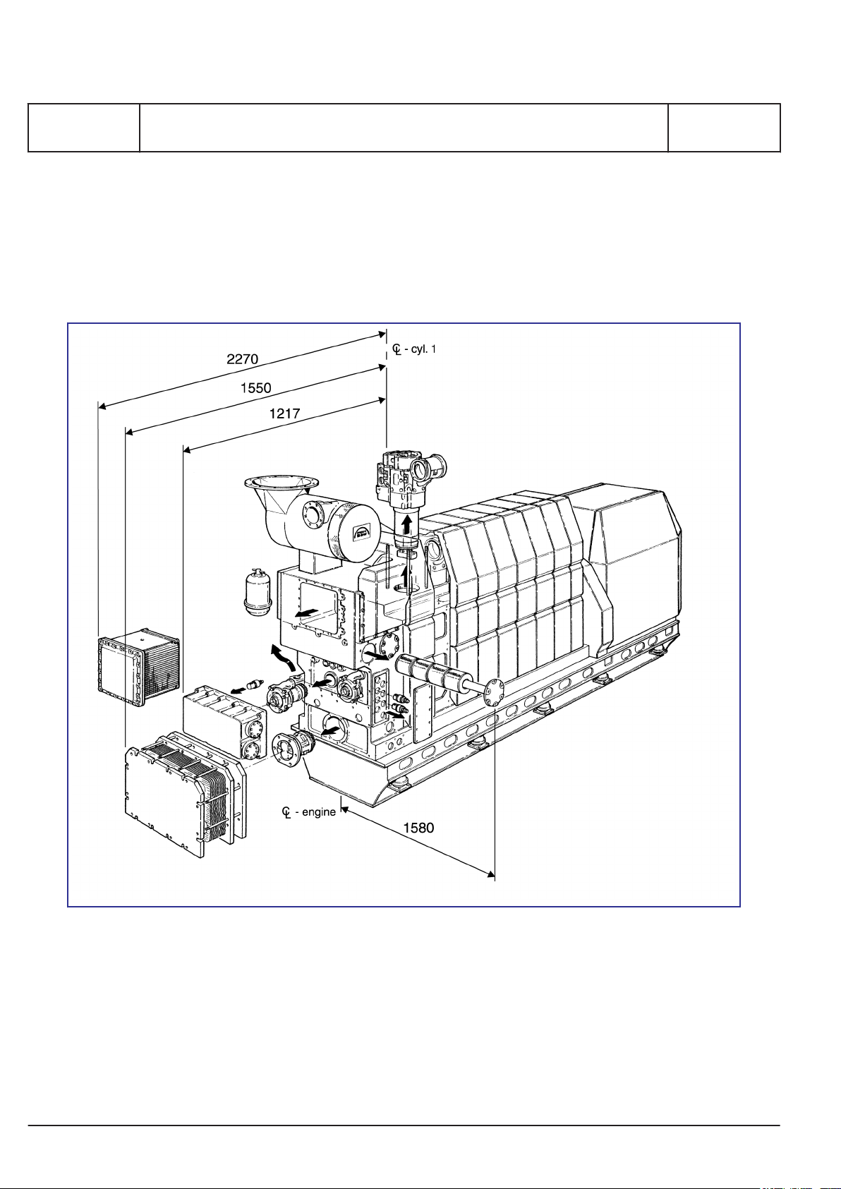
MAN Diesel & Turbo
B 10 01 1
L27/38S, L27/38
Dismantling space
It must be taken into consideration that there is sufficient space for pulling the charge air cooler element, lubricating oil cooler, lubricating oil filter cartridge, lubricating pump and water pumps.
Overhaul areas
1665770-6.6
Page 4 (4)
Figure 2: Overhaul areas for charge air cooler element, lub. oil cooler and lub. oil filter cartridge.
2015.11.27
Page 81

MAN Diesel & Turbo
3700366-0.0
Page 1 (1)
Firing pressure comparison
Firing pressure comparison
B 10 01 1
L27/38S, L27/38
2014.08.14
Page 82

Page 83
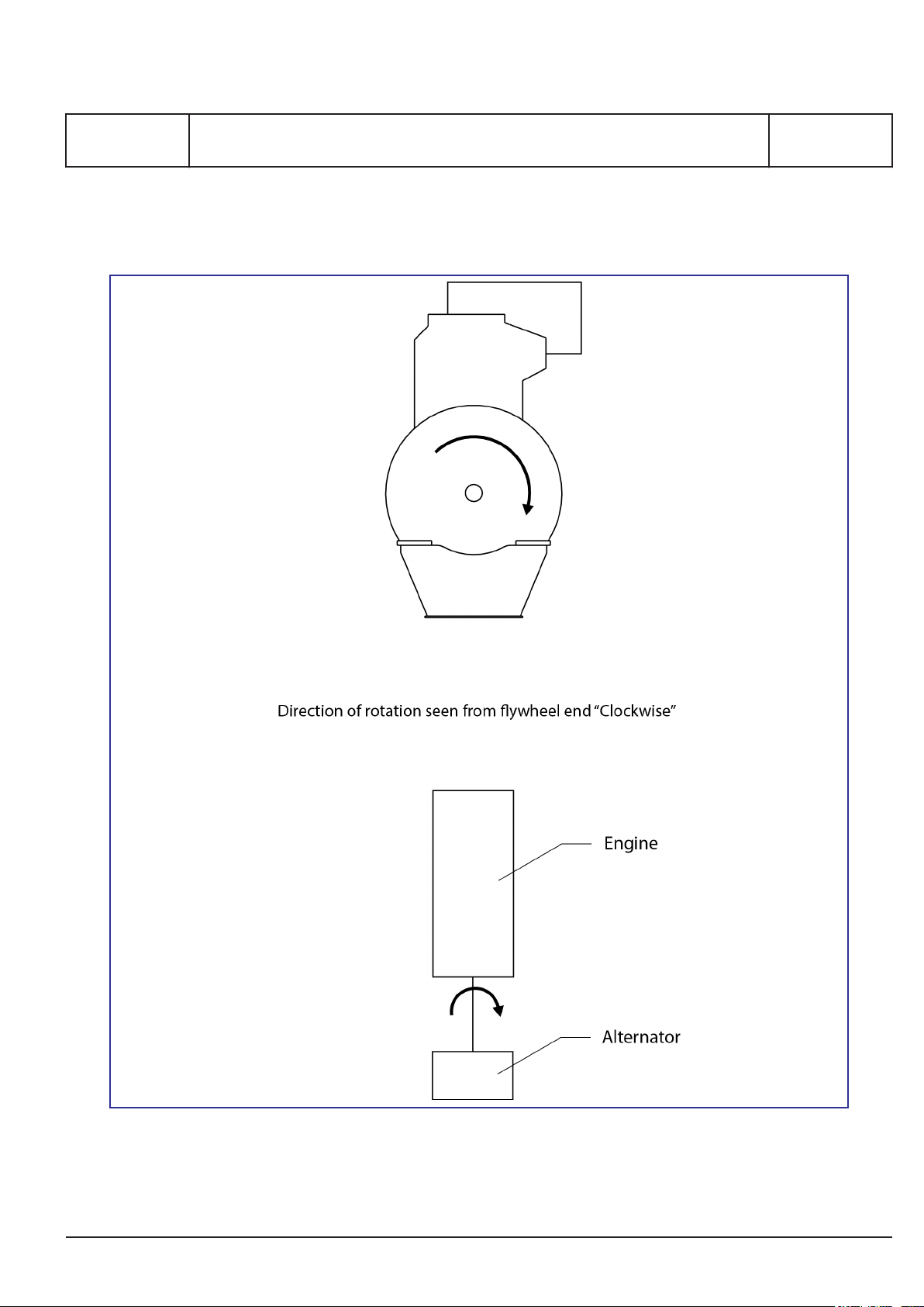
MAN Diesel & Turbo
1607566-7.2
Page 1 (1)
L28/32S, L27/38S, L23/30S, L21/31S, L16/24S, L23/30DF, V28/32S-DF, L28/32DF,
Engine rotation clockwise
Engine rotation clockwise
B 10 11 1
V28/32H, V28/32S, L16/24, L21/31, L23/30H, L27/38, L28/32H
2014.05.19
Page 84

Page 85

MAN Diesel & Turbo
B 11 Fuel oil system
Page 1 (1)
B 11 Fuel oil system
2018-04-13 - en
Page 86

Page 87
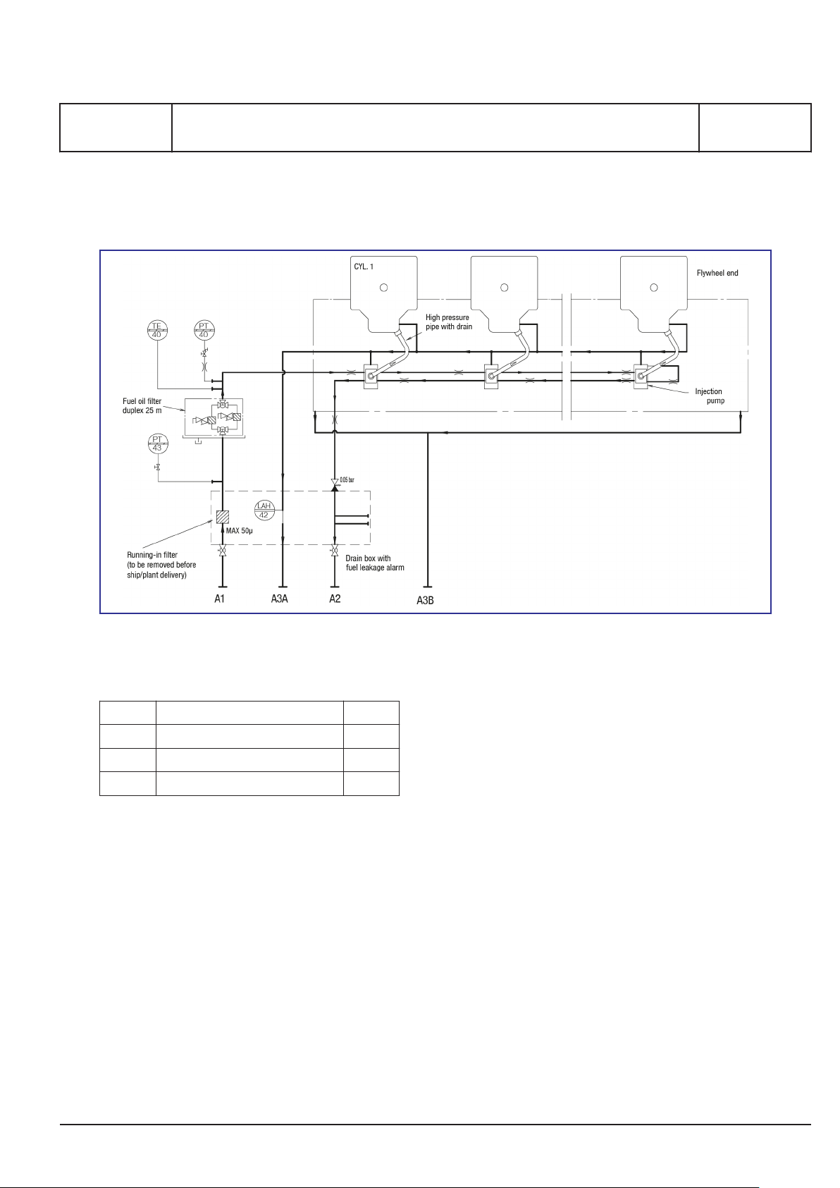
MAN Diesel & Turbo
3700163-4.1
Page 1 (2)
Internal fuel oil system
Internal fuel oil system
B 11 00 0
L27/38S, L27/38
Figure 1: Diagram for fuel oil system (for guidance only, please see plant specific engine diagram)
Running-in filter
Pipe description
A1 Fuel oil inlet DN 25
A2 Fuel oil outlet DN 25
A3A Clean leak oil to service tank DN 15
A3B Waste oil outlet to sludge tank DN 15
Table 1: Flange connections are standard according to DIN 2501
The running-in filter has a fineness of 50 microns
(sphere passing mesh) and is placed in the fuel inlet
pipe. Its function is to remove impurities in the fuel
pipe between safety filter and the engine in the running-in period.
Note: The filter must be removed before ship delivery or before handling over to the customer.
It is adviced to install the filter every time the extern
fuel pipe system has been dismantled, but it is
General
The internal built-on fuel oil system as shown in fig.
1 consists of the following parts:
▪ the running-in filter
▪ the high-pressure injection equipment
▪ the waste oil system
important to remove the filter again when the extern
fuel oil system is considered to be clean for any
impurities.
Fuel oil filter duplex (Safety filter)
GenSets with conventional fuel injection system or
common rail fuel systems are equipped with a fuel
oil filter duplex, with a fineness of max. 25 microns
(sphere passing mesh) The fuel oil filter duplex is
with star-pleated filter elements and allows changeover during operation without pressure-loss. The filter is compact and easy to maintain, requiring only
manual cleaning when maximum allowable pressure
drop is reached. When maximum pressure drop is
2016.02.05 - Drain split
Page 88

MAN Diesel & Turbo
B 11 00 0
Internal fuel oil system
L27/38S, L27/38
reached the standby filter chamber is brought on
line simultaneously as the dirty one is isolated by
means of the change-over valve. After venting, the
dirty element can be removed, cleaned and refilled
to be the standby filter chamber.
Fuel injection equipment
Each cylinder unit has its own set of injection equipment comprising injection pump unit, high-pressure
pipe and injection valve.
The injection equipment and the distribution supply
pipes are housed in a fully enclosed compartment
thus minimizing heat losses from the preheated fuel.
This arrangement reduces external surface temperatures and the risk of fire caused by fuel leakage.
The injection pump units are with integrated roller
guide directly above the camshaft.
The fuel quantity injected into each cylinder unit is
adjusted by means of the governor, which maintains the engine speed at the preset value by a continuous positioning of the fuel pump racks, via a
common regulating shaft and spring-loaded linkages for each pump.
The injection valve is for "deep" building-in to the
centre of the cylinder head.
The injection oil is supplied from the injection pump
to the injection valve via a double-walled pressure
pipe installed in a bore in the cylinder head.
This bore has an external connection to lead the
leak oil from the injection valve and high-pressure
pipe to the waste oil system, through the double
walled pressure pipe.
A bore in the cylinder head vents the space below
the bottom rubber sealing ring on the injection
valve, thus preventing any pressure build-up due to
gas leakage, but also unveiling any malfunction of
the bottom rubber sealing ring due to leak oil.
Waste oil system
Clean leak oil from the fuel injection valves, fuel
injection pumps and high-pressure pipes, is led to
the fuel leakage alarm unit, from which it is drained
into the clean leak fuel oil tank.
The leakage alarm unit consists of a box, with a
float switch for level monitoring. In case of a leakage, larger than normal, the float switch will initiate
an alarm. The supply fuel oil to the engine is led
3700163-4.1
Page 2 (2)
through the leakage alarm unit in order to keep this
heated up, thereby ensuring free drainage passage
even for high-viscous waste/leak oil.
Waste and leak oil from the hot box is drained into
the sludge tank.
Clean leak fuel tank
Clean leak fuel is drained by gravity from the engine.
The fuel should be collected in a separate clean
leak fuel tank, from where it can be pumped to the
service tank and reused without separation. The
pipes from the engine to the clean leak fuel tank
should be arranged continuously sloping. The tank
and the pipes must be heated and insulated, unless
the installation is designed for operation exclusively
on MDO/MGO.
The leak fuel piping should be fully closed to pre-
vent dirt from entering the system.
Sludge tank
In normal operation no fuel should leak out from the
components of the fuel system. In connection with
maintenance, or due to unforeseen leaks, fuel or
water may spill in the hot box of the engine. The
spilled liquids are collected and drained by gravity
from the engine through the dirty fuel connection.
Waste and leak oil from the hot box is drained into
the sludge tank.
The tank and the pipes must be heated and insula-
ted, unless the installation is designed for operation
exclusively on MDO/MGO.
Data
For pump capacities, see "
ties
"
Fuel oil consumption for emissions standard is sta-
ted in "
sions standard
Set points and operating levels for temperature and
pressure are stated in "
set points
B 11 01 0 Fuel oil consumption for emis-
"
"
D 10 05 0 List of capaci-
B 19 00 0 operation data &
2016.02.05 - Drain split
Page 89

MAN Diesel & Turbo
3700499-0.1
Page 1 (2)
Part-load optimisation - PLO
V28/32S, L28/32S, L28/32H, L27/38S, L27/38, L23/30S, L23/30H, L21/31S,
Description
MAN Diesel & Turbo is continuously adapting our
engine programme to the changing market conditions.
At the request of various shipowners, we have
developed and introduced a new IMO Tier II/III compliant tuning method for GenSets which mostly
operate below the normal 75% MCR.
The new tuning method is referred to as part load
optimisation (PLO), and it is recommended for GenSets which mostly run below 75% MCR.
Traditionally, GenSets are fuel oil optimised at 85%
MCR, but with PLO tuning, the engine performance
is optimised at approx. 60-65% MCR, which
ensures optimisation in the low-and part-load areas.
The most obvious benefit of applying PLO is the fuel
oil saving of, typically, up to 5 g/kWh, depending on
engine type/model and load point.
Furthermore, thanks to the improved combustion
process resulting from the optimised nozzle ring in
the turbocharger, valuable engine components,
such as pistons, fuel equipment, valves and T/C
nozzle ring, will be operating under optimal conditions at the given load.
The GenSets are fully compliant with IMO Tier II,
even though the fuel oil consumption is reduced in
the low and part load area, as a fuel oil penalty is
imposed in the high load range.
B1100 0
L21/31, L16/24S, L16/24
Figure 1: SFOC-curves from first delivery of PLO
Page 90

MAN Diesel & Turbo
B1100 0
Part-load optimisation - PLO
V28/32S, L28/32S, L28/32H, L27/38S, L27/38, L23/30S, L23/30H, L21/31S,
L21/31, L16/24S, L16/24
However, a fuel oil penalty will rarely occur, since it
is unusual that GenSets operate beyond 75% load,
because the power management system will
engage an additional GenSet when more power is
needed.
PLO will give the same relative advantage when
applied in combination with SCR-systems for IMO
Tier III compliance.
▪ New turbocharger arrangement for optimised
part-load operation
▪ Blow-off arrangement on charge air receiver to
prevent “over-boosting” of engine at MCR operation
▪ New valve cam for optimised valve overlap for
SFOC optimisation
▪ Change of timing for delayed injection optimisa-
tion of SFOC vs. NOx emissions
3700499-0.1
Page 2 (2)
Page 91

MAN Diesel & Turbo
Specification of heavy fuel oil (HFO)
Prerequisites
MAN Diesel & Turbo four-stroke diesel engines can be operated with any
heavy fuel oil obtained from crude oil that also satisfies the requirements in
table The fuel specification and corresponding characteristics for heavy fuel
oil providing the engine and fuel processing system have been designed
accordingly. To ensure that the relationship between the fuel, spare parts
and repair / maintenance costs remains favourable at all times, the following
points should be observed.
Heavy fuel oil (HFO)
010.000.023-05
Origin/Refinery process
Specifications
Important
2017-07-11 - de
Blends
The quality of the heavy fuel oil largely depends on the quality of crude oil
and on the refining process used. This is why the properties of heavy fuel oils
with the same viscosity may vary considerably depending on the bunker
positions. Heavy fuel oil is normally a mixture of residual oil and distillates.
The components of the mixture are normally obtained from modern refinery
processes, such as Catcracker or Visbreaker. These processes can
adversely affect the stability of the fuel as well as its ignition and combustion
properties. The processing of the heavy fuel oil and the operating result of
the engine also depend heavily on these factors.
Bunker positions with standardised heavy fuel oil qualities should preferably
be used. If oils need to be purchased from independent dealers, also ensure
that these also comply with the international specifications. The engine oper-
ator is responsible for ensuring that suitable heavy fuel oils are chosen.
Fuels intended for use in an engine must satisfy the specifications to ensure
sufficient quality. The limit values for heavy fuel oils are specified in Table
fuel specification and corresponding characteristics for heavy fuel oil. The
entries in the last column of this Table provide important background infor-
mation and must therefore be observed
The relevant international specification is ISO 8217 in the respectively appli-
cable version. All qualities in these specifications up to K700 can be used,
provided the fuel system has been designed for these fuels. To use any fuels,
which do not comply with these specifications (e.g. crude oil), consultation
with Technical Service of MAN Diesel & Turbo in Augsburg is required. Heavy
fuel oils with a maximum density of 1,010 kg/m3 may only be used if up-to-
date separators are installed.
Even though the fuel properties specified in the table entitled
cation and corresponding properties for heavy fuel oil satisfy the above
requirements, they probably do not adequately define the ignition and com-
bustion properties and the stability of the fuel. This means that the operating
behaviour of the engine can depend on properties that are not defined in the
specification. This particularly applies to the oil property that causes forma-
tion of deposits in the combustion chamber, injection system, gas ducts and
exhaust gas system. A number of fuels have a tendency towards incompati-
bility with lubricating oil which leads to deposits being formed in the fuel
delivery pump that can block the pumps. It may therefore be necessary to
exclude specific fuels that could cause problems.
The addition of engine oils (old lubricating oil, ULO – used lubricating oil) and
additives that are not manufactured from mineral oils, (coal-tar oil, for exam-
ple), and residual products of chemical or other processes such as solvents
(polymers or chemical waste) is not permitted. Some of the reasons for this
The fuel specifi-
The
Specification of heavy fuel oil (HFO) D010.000.023-05-0001
General
D010.000.023-05-0001 EN 1 (13)
Page 92

010.000.023-05
Leak oil collector
Viscosity (at 50 °C) mm2/s (cSt) max. 700 Viscosity/injection viscosity
Viscosity (at 100 °C) max. 55 Viscosity/injection viscosity
Density (at 15 °C) g/ml max. 1.010 Heavy fuel oil preparation
Flash point °C min. 60 Flash point
Pour point (summer) max. 30 Low-temperature behaviour
Pour point (winter) max. 30 Low-temperature behaviour
Coke residue (Conrad-
son)
Sulphur content 5 or
Ash content 0.15 Heavy fuel oil preparation
Vanadium content mg/kg 450 Heavy fuel oil preparation
Water content Vol. % 0.5 Heavy fuel oil preparation
Sediment (potential) weight % 0.1 –
Aluminium and silicon
content (total)
Acid number mg KOH/g 2.5 –
Hydrogen sulphide mg/kg 2 –
Used lube oil (ULO)
(calcium, zinc, phos-
phorus)
MAN Diesel & Turbo
are as follows: abrasive and corrosive effects, unfavourable combustion
characteristics, poor compatibility with mineral oils and, last but not least,
adverse effects on the environment. The order for the fuel must expressly
state what is not permitted as the fuel specifications that generally apply do
not include this limitation.
If engine oils (old lubricating oil, ULO – used lubricating oil) are added to fuel,
this poses a particular danger as the additives in the lubricating oil act as
emulsifiers that cause dirt, water and catfines to be transported as fine sus-
pension. They therefore prevent the necessary cleaning of the fuel. In our
experience (and this has also been the experience of other manufacturers),
this can severely damage the engine and turbocharger components.
The addition of chemical waste products (solvents, for example) to the fuel is
prohibited for environmental protection reasons according to the resolution
of the IMO Marine Environment Protection Committee passed on 1st January
1992.
Leak oil collectors that act as receptacles for leak oil, and also return and
overflow pipes in the lube oil system, must not be connected to the fuel tank.
Leak oil lines should be emptied into sludge tanks.
(ASTM D 93)
(ASTM D 97)
(ASTM D 97)
weight % max. 20 Combustion properties
Sulphuric acid corrosion
legal requirements
mg/kg max. 60 Heavy fuel oil preparation
mg/kg Calcium max. 30 mg/kg
Zinc max. 15 mg/kg
Phosphorus max. 15
mg/kg
The fuel must be free of lube
oil (ULO – used lube oil). A fuel
is considered contaminated
with lube oil if the following
concentrations occur:
Ca > 30 ppm and Zn > 15
ppm or Ca > 30 ppm and P >
15 ppm.
2017-07-11 - de
Specification of heavy fuel oil (HFO) D010.000.023-05-0001
General
2 (13) D010.000.023-05-0001 EN
Page 93

MAN Diesel & Turbo
010.000.023-05
Asphalt content weight % 2/3 of coke residue (acc. to
Conradson)
Sodium content mg/kg Sodium < 1/3 vanadium,
sodium <100
The fuel must be free of admixtures that have not been obtained from petroleum such as vegetable or coal tar oils,
free of tar oil and lube oil (used oil), and free of chemical wastes, solvents or polymers.
Table 1: The fuel specification and the corresponding properties for heavy fuel oil
Combustion properties This
requirement applies accord-
ingly.
Heavy fuel oil preparation
2017-07-11 - de
Specification of heavy fuel oil (HFO) D010.000.023-05-0001
D010.000.023-05-0001 EN 3 (13)
General
Page 94

4 (13) D010.000.023-05-0001 EN
Specification of heavy fuel oil (HFO) D010.000.023-05-0001
General
ISO 8217-2012 HFO specification
Characteristic Unit Limit Category ISO-F- Test method
Kinematic
viscosity
at 50 °C
Density at 15 °C kg/m3Max. 920.0 960.0 975.0 991.0 991.0 1010.0 See 7.1
CCAI – Max. 850 860 860 860 870 870 See 6.3 a)
Sulfur
Flash point °C Min. 60.0 60.0 60.0 60.0 60.0 60.0 See 7.3
Hydrogen sulfide mg/kg Max. 2.00 2.00 2.00 2.00 2.00 2.00 See 7.11
Acid number
Total sediment
aged
Carbon residue:
micro method
b
c
mm2/s Max. 10.00 30.00 80.00 180.0 180.0 380.0 500.0 700.0 380.0 500.0 700.0 ISO 3104
% (m/m) Max. Statutory requirements See 7.2
d
mg
KOH/g
% (m/m) Max. 0.10 0.10 0.10 0.10 0.10 0.10 See 7.5
% (m/m) Max. 2.50 10.00 14.00 15.00 18.00 20.00 ISO 10370
RMA RMB RMD RME RMG RMK
a
10
Max. 2.5 2.5 2.5 2.5 2.5 2.5 ASTM D664
30 80 180 180 380 500 700 380 500 700
ISO 3675 or
ISO 12185
ISO 8754
ISO 14596
ISO 2719
IP 570
ISO 10307-2
010.000.023-05
MAN Diesel & Turbo
2017-07-11 - de
Page 95

2017-07-11 - de
D010.000.023-05-0001 EN 5 (13)
Characteristic Unit Limit Category ISO-F- Test method
RMA RMB RMD RME RMG RMK
a
10
Pour point
e
(upper)
Winter quality
Summer quality
Water % (V/V) Max. 0.30 0.50 0.50 0.50 0.50 0.50 ISO 3733
Ash % (m/m) Max. 0.040 0.070 0.070 0.070 0.100 0.150 ISO 6245
Vanadium mg/kg Max. 50 150 150 150 350 450 see 7.7
Sodium mg/kg Max. 50 100 100 50 100 100 see 7.8
Aluminium plus
silicon
Used lubricating
oils (ULO):
calcium and zinc
or
calcium and
phosphorus
a This category is based on a previously defined distillate DMC category that was described in ISO 8217:2005, Table 1. ISO 8217:2005 has been withdrawn.
b 1mm2/s = 1 cSt
c The purchaser shall define the maximum sulfur content in accordance with relevant statutory limitations. See 0.3 and Annex C.
d See Annex H.
e Purchasers shall ensure that this pour point is suitable for the equipment on board, especially if the ship operates in cold climates.
°C
°C
mg/kg Max. 25 40 40 50 60 60 see 7.9
mg/kg
mg/kg
Max.
Max.
– The fuel shall be free from ULO. A fuel shall be considered to contain ULO when either one of the following condi-
0
6
tions is met:
calcium > 30 and zinc > 15
or
calcium > 30 and phosphorus > 15
30 80 180 180 380 500 700 380 500 700
0
6
30
30
30
30
30
30
30
30
ISO 3016
ISO 3016
IP 501, IP 470
or ISO 14597
IP 501, IP 470
IP 501, IP 470
or ISO 10478
(see 7.10) IP
501 or
IP 470
IP 500
MAN Diesel & Turbo
010.000.023-05
Specification of heavy fuel oil (HFO) D010.000.023-05-0001
General
Page 96
6 (13) D010.000.023-05-0001 EN
Specification of heavy fuel oil (HFO) D010.000.023-05-0001
General
010.000.023-05
2017-07-11 - de
MAN Diesel & Turbo
Page 97
MAN Diesel & Turbo
Additional information
Selection of heavy fuel oil
Viscosity/injection viscosity
Heavy fuel oil processing
Settling tank
Separators
2017-07-11 - de
010.000.023-05
The purpose of the following information is to show the relationship between
the quality of heavy fuel oil, heavy fuel oil processing, the engine operation
and operating results more clearly.
Economical operation with heavy fuel oil within the limit values specified in
the table entitled The fuel specification and corresponding properties for
heavy fuel oil is possible under normal operating conditions, provided the
system is working properly and regular maintenance is carried out. If these
requirements are not satisfied, shorter maintenance intervals, higher wear
and a greater need for spare parts is to be expected. The required mainte-
nance intervals and operating results determine which quality of heavy fuel oil
should be used.
It is an established fact that the price advantage decreases as viscosity
increases. It is therefore not always economical to use the fuel with the high-
est viscosity as in many cases the quality of this fuel will not be the best.
Heavy fuel oils with a high viscosity may be of an inferior quality. The maxi-
mum permissible viscosity depends on the preheating system installed and
the capacity (flow rate) of the separator.
The prescribed injection viscosity of 12 – 14 mm2/s (for GenSets, L16/24,
L21/31, L23/30H, L27/38, L28/32H: 12 – 18 cSt) and corresponding fuel
temperature upstream of the engine must be observed. This is the only way
to ensure efficient atomisation and mixture formation and therefore low-resi-
due combustion. This also prevents mechanical overloading of the injection
system. For the prescribed injection viscosity and/or the required fuel oil tem-
perature upstream of the engine, refer to the viscosity temperature diagram.
Whether or not problems occur with the engine in operation depends on how
carefully the heavy fuel oil has been processed. Particular care should be
taken to ensure that highly-abrasive inorganic foreign matter (catalyst parti-
cles, rust, sand) are effectively removed. It has been shown in practice that
wear as a result of abrasion in the engine increases considerably if the alumi-
num and silicium content is higher than 15 mg/kg.
Viscosity and density influence the cleaning effect. This must be taken into
account when designing and making adjustments to the cleaning system.
The heavy fuel oil is pre-cleaned in the settling tank. This pre-cleaning is
more effective the longer the fuel remains in the tank and the lower the vis-
cosity of the heavy fuel oil (maximum preheating temperature 75 °C in order
to prevent the formation of asphalt in the heavy fuel oil). One settling tank is
suitable for heavy fuel oils with a viscosity below 380 mm2/s at 50 °C. If the
heavy fuel oil has high concentrations of foreign material or if fuels according
to ISO-F-RM, G/K380 or K700 are used, two settling tanks are necessary,
one of which must be designed for operation over 24 hours. Before transfer-
ring the contents into the service tank, water and sludge must be drained
from the settling tank.
A separator is particularly suitable for separating material with a higher spe-
cific density – such as water, foreign matter and sludge. The separators must
be self-cleaning (i.e. the cleaning intervals must be triggered automatically).
Only new generation separators should be used. They are extremely effective
throughout a wide density range with no changeover required, and can sep-
arate water from heavy fuel oils with a density of up to 1.01 g/ml at 15 °C.
Specification of heavy fuel oil (HFO) D010.000.023-05-0001
D010.000.023-05-0001 EN 7 (13)
General
Page 98
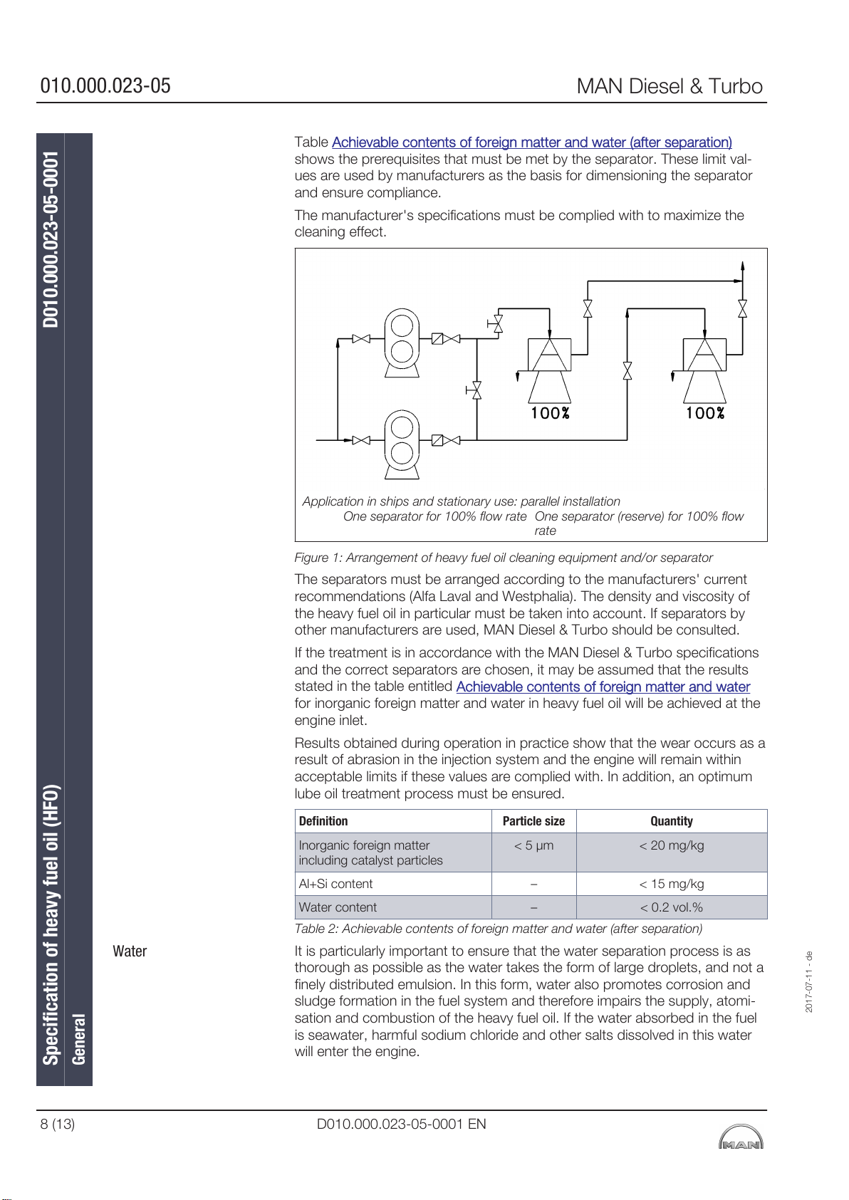
010.000.023-05
MAN Diesel & Turbo
Table Achievable contents of foreign matter and water (after separation)
shows the prerequisites that must be met by the separator. These limit val-
ues are used by manufacturers as the basis for dimensioning the separator
and ensure compliance.
The manufacturer's specifications must be complied with to maximize the
cleaning effect.
Water
Specification of heavy fuel oil (HFO) D010.000.023-05-0001
General
Application in ships and stationary use: parallel installation
One separator for 100% flow rate One separator (reserve) for 100% flow
rate
Figure 1: Arrangement of heavy fuel oil cleaning equipment and/or separator
The separators must be arranged according to the manufacturers' current
recommendations (Alfa Laval and Westphalia). The density and viscosity of
the heavy fuel oil in particular must be taken into account. If separators by
other manufacturers are used, MAN Diesel & Turbo should be consulted.
If the treatment is in accordance with the MAN Diesel & Turbo specifications
and the correct separators are chosen, it may be assumed that the results
stated in the table entitled
Achievable contents of foreign matter and water
for inorganic foreign matter and water in heavy fuel oil will be achieved at the
engine inlet.
Results obtained during operation in practice show that the wear occurs as a
result of abrasion in the injection system and the engine will remain within
acceptable limits if these values are complied with. In addition, an optimum
lube oil treatment process must be ensured.
Definition Particle size Quantity
Inorganic foreign matter
including catalyst particles
Al+Si content – < 15 mg/kg
Water content – < 0.2 vol.%
Table 2: Achievable contents of foreign matter and water (after separation)
< 5 µm < 20 mg/kg
It is particularly important to ensure that the water separation process is as
thorough as possible as the water takes the form of large droplets, and not a
finely distributed emulsion. In this form, water also promotes corrosion and
sludge formation in the fuel system and therefore impairs the supply, atomi-
sation and combustion of the heavy fuel oil. If the water absorbed in the fuel
is seawater, harmful sodium chloride and other salts dissolved in this water
will enter the engine.
2017-07-11 - de
8 (13) D010.000.023-05-0001 EN
Page 99
MAN Diesel & Turbo
Vanadium/Sodium
Ash
Homogeniser
Flash point (ASTM D 93)
Low-temperature behaviour
(ASTM D 97)
Pump characteristics
Combustion properties
2017-07-11 - de
010.000.023-05
Water-containing sludge must be removed from the settling tank before the
separation process starts, and must also be removed from the service tank
at regular intervals. The tank's ventilation system must be designed in such a
way that condensate cannot flow back into the tank.
If the vanadium/sodium ratio is unfavourable, the melting point of the heavy
fuel oil ash may fall in the operating area of the exhaust-gas valve which can
lead to high-temperature corrosion. Most of the water and water-soluble
sodium compounds it contains can be removed by pretreating the heavy fuel
oil in the settling tank and in the separators.
The risk of high-temperature corrosion is low if the sodium content is one
third of the vanadium content or less. It must also be ensured that sodium
does not enter the engine in the form of seawater in the intake air.
If the sodium content is higher than 100 mg/kg, this is likely to result in a
higher quantity of salt deposits in the combustion chamber and exhaust-gas
system. This will impair the function of the engine (including the suction func-
tion of the turbocharger).
Under certain conditions, high-temperature corrosion can be prevented by
using a fuel additive that increases the melting point of heavy fuel oil ash (also
see
Additives for heavy fuel oils).
Fuel ash consists for the greater part of vanadium oxide and nickel sulphate
(see above section for more information). Heavy fuel oils containing a high
proportion of ash in the form of foreign matter, e.g. sand, corrosion com-
pounds and catalyst particles, accelerate the mechanical wear in the engine.
Catalyst particles produced as a result of the catalytic cracking process may
be present in the heavy fuel oils. In most cases, these catalyst particles are
aluminium silicates causing a high degree of wear in the injection system and
the engine. The aluminium content determined, multiplied by a factor of
between 5 and 8 (depending on the catalytic bond), is roughly the same as
the proportion of catalyst remnants in the heavy fuel oil.
If a homogeniser is used, it must never be installed between the settling tank
and separator as otherwise it will not be possible to ensure satisfactory sepa-
ration of harmful contaminants, particularly seawater.
National and international transportation and storage regulations governing
the use of fuels must be complied with in relation to the flash point. In gen-
eral, a flash point of above 60 °C is prescribed for diesel engine fuels.
The pour point is the temperature at which the fuel is no longer flowable
(pumpable). As the pour point of many low-viscosity heavy fuel oils is higher
than 0 °C, the bunker facility must be preheated, unless fuel in accordance
with RMA or RMB is used. The entire bunker facility must be designed in
such a way that the heavy fuel oil can be preheated to around 10 °C above
the pour point.
If the viscosity of the fuel is higher than 1000 mm2/s (cSt), or the temperature
is not at least 10 °C above the pour point, pump problems will occur. For
more information, also refer to paragraph Low-temperature behaviour (ASTM
D 97.
If the proportion of asphalt is more than two thirds of the coke residue (Con-
radson), combustion may be delayed which in turn may increase the forma-
tion of combustion residues, leading to such as deposits on and in the injec-
tion nozzles, large amounts of smoke, low output, increased fuel consump-
tion and a rapid rise in ignition pressure as well as combustion close to the
cylinder wall (thermal overloading of lubricating oil film). If the ratio of asphalt
to coke residues reaches the limit 0.66, and if the asphalt content exceeds
8%, the risk of deposits forming in the combustion chamber and injection
Specification of heavy fuel oil (HFO) D010.000.023-05-0001
General
D010.000.023-05-0001 EN 9 (13)
Page 100

010.000.023-05
Ignition quality
MAN Diesel & Turbo
system is higher. These problems can also occur when using unstable heavy
fuel oils, or if incompatible heavy fuel oils are mixed. This would lead to an
increased deposition of asphalt (see paragraph Compatibility).
Nowadays, to achieve the prescribed reference viscosity, cracking-process
products are used as the low viscosity ingredients of heavy fuel oils although
the ignition characteristics of these oils may also be poor. The cetane num-
ber of these compounds should be > 35. If the proportion of aromatic hydro-
carbons is high (more than 35 %), this also adversely affects the ignition
quality.
The ignition delay in heavy fuel oils with poor ignition characteristics is longer;
the combustion is also delayed which can lead to thermal overloading of the
oil film at the cylinder liner and also high cylinder pressures. The ignition delay
and accompanying increase in pressure in the cylinder are also influenced by
the end temperature and compression pressure, i.e. by the compression
ratio, the charge-air pressure and charge-air temperature.
The disadvantages of using fuels with poor ignition characteristics can be
limited by preheating the charge air in partial load operation and reducing the
output for a limited period. However, a more effective solution is a high com-
pression ratio and operational adjustment of the injection system to the igni-
tion characteristics of the fuel used, as is the case with MAN Diesel & Turbo
piston engines.
The ignition quality is one of the most important properties of the fuel. This
value appears as CCAI in ISO 8217. This method is only applicable to
"straight run" residual oils. The increasing complexity of refinery processes
has the effect that the CCAI method does not correctly reflect the ignition
behaviour for all residual oils.
A testing instrument has been developed based on the constant volume
combustion method (fuel combustion analyser FCA), which is used in some
fuel testing laboratories (FCA) in conformity with IP 541.
The instrument measures the ignition delay to determine the ignition quality
of a fuel and this measurement is converted into an instrument-specific
cetane number (ECN: Estimated Cetane Number). It has been determined
that heavy fuel oils with a low ECN number cause operating problems and
may even lead to damage to the engine. An ECN >20 can be considered
acceptable.
As the liquid components of the heavy fuel oil decisively influence the ignition
quality, flow properties and combustion quality, the bunker operator is
responsible for ensuring that the quality of heavy fuel oil delivered is suitable
for the diesel engine. Also see illustration entitled
the CCAI – assigning the CCAI ranges to engine types.
Nomogram for determining
Specification of heavy fuel oil (HFO) D010.000.023-05-0001
General
10 (13) D010.000.023-05-0001 EN
2017-07-11 - de
 Loading...