

Page 1

Page 2

Page 3

Foreword
Dear Customer
The purpose of these installation instructions is to:
D provide assistance and advice in the installation of the MAN Marine Diesel Engines V8−1200 and
V12−1800
D establish the conditions for trouble−free operation of the drive line and avoid installation−related
malfunctions and any resulting consequential damage.
These installation instructions apply to the installation of MAN Marine Diesel Engines V8−1200 and
V12−1800 in yachts.
During the installation and operation of MAN Marine Diesel Engines the applicable laws, statutes and
regulations for the area and range of use must be observed.
The currently applicable accident prevention regulations as well as all other generally recognised health
and safety and safety at work regulations must also be observed.
Caution:
MAN is only liable for material defects when these installation instructions have been observed.
On request and against payment, MAN will perform acceptance tests for installations. Certifications of
prototypes are only valid for series installations, provided that no retroactive modifications are carried out.
If you intend to modify a built−in engine component which has been acceptance−tested by MAN, you must
notify MAN in writing as a further acceptance test may be required.
Sincerely,
MAN Nutzfahrzeuge Aktiengesellschaft
Werk Nürnberg
Subject to technical alterations in the interests of further development.
© 2009 MAN Nutzfahrzeuge Aktiengesellschaft
Reprinting, copying or translation, even of extracts, is not allowed without written permission from MAN. All
rights under the copyright law are strictly reserved by MAN.
EMDGG Technical status: 03.2009 51.99496−8180
1
Page 4

Contents
Page
Foreword 1. . . . . . . . . . . . . . . . . . . . . . . . . . . . . . . . . . . . . . . . . . . . . . . . .
Safety regulations 3. . . . . . . . . . . . . . . . . . . . . . . . . . . . . . . . . . . . . . . . . . . . . . . . . . . . . . . . . . . . . . . . . . . . . . . .
Planning of engine installation 10. . . . . . . . . . . . . . . . . . . . . . . . . . . . . . . . . . . . . . . . . . .
Accessibility of engine in engine room 13. . . . . . . . . . . . . . . . . . . . . . . . . . . . . . . . . . . . . . . . . . . . . . . . . . . . . . .
Engine foundation 16. . . . . . . . . . . . . . . . . . . . . . . . . . . . . . . . . . . . . . . . . . . . . . . . . . . . . . . . . . . . . . . . . . . . . . . .
Engine mounting 18. . . . . . . . . . . . . . . . . . . . . . . . . . . . . . . . . . . . . . . . . . . . . . . . . . . . . . . . . . . . . . . . . . . . . . . . .
Engine room ventilation 22. . . . . . . . . . . . . . . . . . . . . . . . . . . . . . . . . . . . . . . . . . . . . . . . . . . . . . . . . . . . . . . . . . .
Crane transport of the engine 25. . . . . . . . . . . . . . . . . . . . . . . . . . . . . . . . . . . . . . . . . . . . . . . . . . . . . . . . . . . . . .
Flange mounting a gearbox 26. . . . . . . . . . . . . . . . . . . . . . . . . . . . . . . . . . . . . . . . . . . . . . . . . . . . . . . . . . . . . . . .
Aligning an engine with flange−mounted gearbox 29. . . . . . . . . . . . . . . . . . . . . . . . . . . . . . . . . . . . . . . . . . . . . .
Transmission of power by propshafts 32. . . . . . . . . . . . . . . . . . . . . . . . . . . . . . . . . . . . . . . . . . . . . . . . . . . . . . .
Combustion air system and charging 38. . . . . . . . . . . . . . . . . . . . . . . . . . . . . . . . . . . . . . . . . . . . . . . . . . . . . . . .
Exhaust system 40. . . . . . . . . . . . . . . . . . . . . . . . . . . . . . . . . . . . . . . . . . . . . . . . . . . . . . . . . . . . . . . . . . . . . . . . . .
Cooling system 45. . . . . . . . . . . . . . . . . . . . . . . . . . . . . . . . . . . . . . . . . . . . . . . . . . . . . . . . . . . . . . . . . . . . . . . . . .
Fuel system 50. . . . . . . . . . . . . . . . . . . . . . . . . . . . . . . . . . . . . . . . . . . . . . . . . . . . . . . . . . . . . . . . . . . . . . . . . . . . .
Propeller system 54. . . . . . . . . . . . . . . . . . . . . . . . . . . . . . . . . . . . . . . . . . . . . . . . . . . . . . . . . . . . . . . . . . . . . . . . .
Auxiliary power take−off 58. . . . . . . . . . . . . . . . . . . . . . . . . . . . . . . . . . . . . . . . . . . . . . . . . . . . . . . . . . . . . . . . . . .
Electrical system 59. . . . . . . . . . . . . . . . . . . . . . . . . . . . . . . . . . . . . . . . . . . . . . . . . . . . . . . . . . . . . . . . . . . . . . . . .
Electrical preheating of coolant 63. . . . . . . . . . . . . . . . . . . . . . . . . . . . . . . . . . . . . . . . . . . . . . . . . . . . . . . . . . . . .
Cabin heater 64. . . . . . . . . . . . . . . . . . . . . . . . . . . . . . . . . . . . . . . . . . . . . . . . . . . . . . . . . . . . . . . . . . . . . . . . . . . . .
Throttle lever control system 66. . . . . . . . . . . . . . . . . . . . . . . . . . . . . . . . . . . . . . . . . . . . . . . . . . . . . . . . . . . . . . .
First commissioning − Lube oil system 72. . . . . . . . . . . . . . . . . . . . . . . . . . . . . . . . . . . . . . . . . . . . . . . . . . . . . . .
First commissioning − Cooling system 73. . . . . . . . . . . . . . . . . . . . . . . . . . . . . . . . . . . . . . . . . . . . . . . . . . . . . . .
Appendix 77. . . . . . . . . . . . . . . . . . . . . . . . . . . . . . . . . . . . . . . . . . . . . . . . . . . . . . . . . . . . . . . . . . . . . . . . . . . . . . . .
Tightening torques for bolted connections 79. . . . . . . . . . . . . . . . . . . . . . . . . . . . . . . . . . . . . . . . . . . . . . . . .
Technical data 81. . . . . . . . . . . . . . . . . . . . . . . . . . . . . . . . . . . . . . . . . . . . . . . . . . . . . . . . . . . . . . . . . . . . . . . .
MMDS CAN−Bus (V8−1200, V12−1800) 85. . . . . . . . . . . . . . . . . . . . . . . . . . . . . . . . . . . . . . . . . . . . . . . . . . .
Potentialfree wiring diagram of basic components 87. . . . . . . . . . . . . . . . . . . . . . . . . . . . . . . . . . . . . . . .
Index 89. . . . . . . . . . . . . . . . . . . . . . . . . . . . . . . . . . . . . . . . . . . . . . . . . . . . . . . . . . . . . . . . . . . . . . . . . . . . . . . . . . .
. . . . . . . . . . . . . . . . . . . . . . . . . . . . . . .
. . . . . . . . . . . . . . . . . . .
2
Page 5
Safety regulations
ËË
General notes
This summary is a compilation of the most important regulations. These are broken down into main
sections which contain the information necessary for preventing injury to persons, damage to property and
pollution. In addition to these regulations those dictated by the type of engine and its site are to be
observed also.
Important:
If, despite all precautions, an accident occurs, in particular through contact with caustic acids, fuel
penetrating the skin, scalding from hot oil, anti‐freeze being splashed in the eyes etc., consult a doctor
immediately.
1. Regulations designed to prevent accidents with injury to persons
During commissioning, starting and operation
D Before putting the engine into operation for the first time, read the operating instructions
carefully and familiarize yourself with the “critical" points. If you are unsure, ask your
MAN representative.
D For reasons of safety we recommend you attach a notice to the door of the engine
room prohibiting the access of unauthorized persons and that you draw the attention of
the operating personal to the fact that they are responsible for the safety of persons
who enter the engine room.
D The engine must be started and operated only by authorized personnel.
Ensure that the engine cannot be started by unauthorized persons.
D When the engine is running, do not get too close to the rotating parts. Wear close‐fitting
clothing.
D Do not touch the engine with bare hands when it is warm from operation − risk of burns.
D Exhaust gases are toxic. Comply with the instructions for the installation of MAN Diesel
engines which are to be operated in enclosed spaces. Ensure that there is adequate
ventilation and air extraction.
3
Page 6
Safety regulations
D For safety reasons a separate, functioning red emergency‐stop‐button for each
engine must be installed at every bridge (the engine must stop immediately when
the button is pressed once).
D Electrical accessories and equipment from other manufactures may only be
connected without the approval of MAN to the connections provided for the customer or shipyard.
The control of the engine may be adversely affected and thus may lead to property
damage or personal injury and is therefore not permitted.
MAN assumes no liability for any property damage or personal injury.
Connections to the following MAN components are prohibited:
− EDC engine control unit (K−Line, CAN−Bus)
−MAN internal or external throttle lever control system (CAN−Bus)
− Emergency steering control (serial, CAN−Bus)
− Display systems for alarms (serial, CAN−Bus)
Approved connectors on terminal box: X4, X8 and X9.
D Keep vicinity of engine, ladders and stairways free of oil and grease.
Accidents caused by slipping can have serious consequences.
During maintenance and care
D Always carry out maintenance work when the engine is switched off.
If the engine has to be maintained while it is running, e.g. changing the elements of
change‐over filters, remember that there is a risk of scalding. Do not get too close to
rotating parts.
D Change the oil when the engines is warm from operation.
Caution:
There is a risk of burns and scalding. Do not touch oil drain plugs or oil filters with bare
hands.
D Take into account the amount of oil in the sump. Use a vessel of sufficient size to
ensure that the oil will not overflow.
D Open the coolant circuit only when the engine has cooled down.
If opening while the engine is still warm is unavoidable, comply with the instructions in
the chapter entitled “Maintenance and Care".
D Neither tighten up nor open pipes and hoses (lube oil circuit, coolant circuit and any
additional hydraulic oil circuit) during the operation.
The fluids which flow out can cause injury.
D Fuel is inflammable. Do not smoke or use naked lights in its vicinity. The tank must be
filled only when the engine is switched off.
D Keep service products (anti‐freeze) only in containers which can not be confused with
drinks containers.
D Comply with the manufacturer’s instructions when handling batteries.
Caution:
Accumulator acid is toxic and caustic. Battery gases are explosive.
4
Page 7

Safety regulations
2. Regulations designed to prevent damage to engine and premature wear
Do not demand more from the engine than it is able to supply in its intended application. Detailed
information on this can be found in the sales literature.
If faults occur, find the cause immediately and have it eliminated in order to prevent more serious damage.
Use only genuine MAN spare parts.
installation of other parts which are supposedly “just as good".
In addition to the above, note the following points:
D Never let the engine run when dry, i.e. without lube oil or coolant.
D When starting do not use any additional starting aids
D Use only MAN‐approved service products (fuel, engine oil, anti‐freeze and anti‐corrosion agent). Pay
attention to cleanliness. The Diesel fuel must be free of water. See “Fuels, Lubricants and Coolants ...".
D Have the engine maintained at the specified intervals.
D Today modern components of diesel injection consist of high‐precision parts which are exposed to
extreme stresses. The high‐precision technology requires the utmost cleanliness during all work on
the fuel system.
Even a particle of dirt over 0,2 mm can lead to the failure of components.
D Do not switch off the engine immediately when it is warm, but let it run without load for about 5 minutes
so that temperature equalization can take place.
D Never put cold coolant into an overheated engine. See “Maintenance and care".
D Do not add so much engine oil that the oil level rises above the max. marking on the dipstick.
Do not exceed the maximum permissible tilt of the engine.
Serious damage to the engine may result if these instructions are not adhered to.
D Always ensure that the testing and monitoring equipment (for battery charge, oil pressure, coolant
temperature) function satisfactorily.
MAN will accept no responsibility for damage resulting from the
(e.g. injection with starting pilot).
D It is advisable to switch off the engine if an alarm of any kind is displayed in the engine monitoring and
diagnostic system. If this is not possible for any reason, the engine should be run no faster than
1200 rpm until the fault is remedied, see Operating Instructions.
D Comply with instructions for operation of the alternator. See “Operating Instructions".
D Do not let the seawater pump run dry. If there is a risk of frost, drain the pump when the engine is
switched off.
5
Page 8

Safety regulations
3. Regulations designed to prevent pollution
Engine oil and filter elements / cartridges, fuel / fuel filter
D Take old oil only to an old oil collection point.
D Take strict precautions to ensure that no oil or Diesel fuel gets into the drains or the ground.
Caution:
The drinking water supply could be contaminated.
D Filter elements are classed as dangerous waste and must be treated as such.
Coolant
D Treat undiluted anti‐corrosion agent and / or anti‐freeze as dangerous waste.
D When disposing of spent coolant comply with the regulations of the relevant local authorities.
4. Notes on safety in handling used engine oil ∗
Prolonged or repeated contact between the skin and any kind of engine oil decreases the skin. Drying,
irritation or inflammation of the skin may therefore occur. Used engine oil also contains dangerous
substances which have caused skin cancer in animal experiments. If the basic rules of hygiene and health
and safety at work are observed, health risks are not to the expected as a result of handling used engine
oil.
Health precautions:
D Avoid prolonged or repeated skin contact with used engine oil.
D Protect your skin by means of suitable agents (creams etc.) or wear protective gloves.
D Clean skin which has been in contact with engine oil.
− Wash thoroughly with soap and water. A nailbrush is an effective aid.
− Certain products make it easier to clean your hands.
−Do not use petrol, Diesel fuel, gas oil, thinners or solvents as washing agents.
D After washing apply a fatty skin cream to the skin.
D Change oil‐soaked clothing and shoes.
D Do not put oily rags into your pockets.
Ensure that used engine oil is disposed of properly
− Engine oil can endanger the water supply −
For this reason do not let engine oil get into the ground, waterways, the drains or the sewers. Violations are
punishable.
Collect and dispose of used engine oil carefully. For information on collection points please contact the
seller, the supplier or the local authorities.
∗ Adapted from “Notes on handling used engine oil".
6
Page 9
Safety regulations
5. Special instructions when working on the common rail system
Accident protection
D Risk of injury!
Fuel jets can cut through skin.
The atomisation of fuel creates a fire risk.
− When the engine is running never loosen the screw connections on the fuel’s
high‐pressure side of the common rail system (injection line from the high‐pressure
pump to the rail, on the rail and on the cylinder head to the injector)
− Keep away from the engine when it is running
D Risk of injury!
When the engine is running the lines are constantly under a fuel pressure of up
to 1600 bar.
− Wait at least a minute until the pressure in the rail has dropped before loosening a
screw connection
−If necessary check the pressure drop in the rail with MAN‐Cats
D Risk of injury!
− People with pacemaker must keep at least 20 cm away from the running engine.
−Do not touch live parts on the electric connection of the injectors when the engine is
running.
7
Page 10

Safety regulations
Cleanliness
Today modern components of diesel injection consist of high‐precision parts which are exposed to extreme
stresses. The high‐precision technology requires the utmost cleanliness during all work on the fuel
system.
Even a particle of dirt over 0,2 mm can lead to the failure of components.
The measures described as follows are therefore essential before work begins:
Risk of damage from penetration of dirt!
D Before working on the clean side of the fuel system clean the engine and the engine
compartment. During cleaning the fuel system must be closed.
D Carry out visual inspection for any leakage or damage to the fuel system
D Do not spray the high‐pressure cleaner direct onto the electric components, or
alternatively keep them covered
D Do not carry out any welding or sanding work in the engine compartment during
maintenance / repair
D Avoid air movements (any swirling of dust when starting engines)
D The area of the still closed fuel system must be cleaned and dried with the aid of
compressed air
D Remove detached particles of dirt such as paint chippings and insulation material with a
suitable extractor (industrial type vacuum cleaner)
D Cover areas of the engine compartment from which dust particles could be detached
with clean foil
D Wash your hands and put on clean work clothes before starting the disassembly work
When carrying out the work it is essential to comply with the following measures:
8
Page 11

Safety regulations
Risk of damage from penetration of dirt!
D When the clean side of the fuel system has been opened it is not permissible to use
compressed air for cleaning
D During assembly work loose dirt must be removed with the aid of suitable extractors
(industrial type vacuum cleaners)
D Use only fluff‐free cleaning cloths on the fuel system
D Clean tools and working materials before starting to work
D Only tools without any damage may be used (cracked chrome coatings)
D When removing and installing components do not use materials such as cloths,
cardboard or wood since these could shed particles and fine fibres
D If any paint chips/flakes off when connections are loosened (from possible over‐coating)
these chippings must be carefully removed before finally loosening the screw
connection
D The connection openings of all parts removed from the clean side of the fuel system
must be immediately closed up with suitable caps/stoppers
D These caps/stoppers must be packed protected from dust prior to use and after being
used once they must be disposed of
D Following this all the components must be carefully stored in a clean, closed container
D Never use used cleaning or testing liquids for these components
D New parts must not be removed from their original packing material until directly before
use
D Work on removed components may be carried out only at a workplace specially
equipped for it
D If removed parts are shipped always use the original packing material of the new part
9
Page 12
Planning of engine installation
V12−1800
5
4
1
2
3
V8−1200
11
6
7
8
9
10
4
10
Page 13

Planning of engine installation
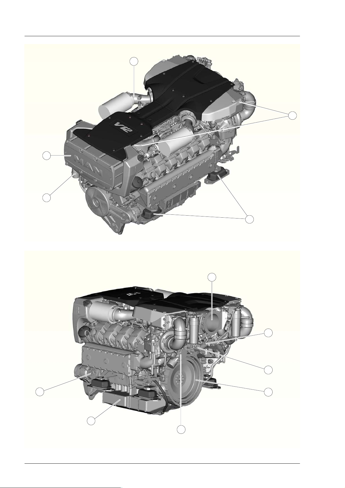
The engines
The figures on page 10 show typical views of the V12 and V8 engines without gearboxes. Currently the
following engine models are available for delivery:
V12−1800
1324 kW (1800 HP)
V8−1200
882 kW (1200 HP)
Engine environment − interface between engine and ship
Here is a summary of important information on individual components to be observed when installing
engines. Each of these components has a connection to a ship−side component. Their correct installation
contributes to the trouble−free operation of the engine.
À Intake system, see page 39
Á Charge air cooling, see page 45
 Engine mounting, see page 20
à Seawater circuit, seawater pump, see page 45
Ä Engine cooling system, see page 45
Å Exhaust system, see page 40
Æ Fuel system, see page 51
Ç Power take−off, see page 58
È Flywheel, power transfer, see page 27
É Lube oil system, see page 72
11
Electrical system, see page 59
11
Page 14

Planning of engine installation
Additional information for planning the installation
In addition to this brochure there are several other documents that are required to plan the installation of
the engine that are not contained in this brochure. The scope of these documents depend on the delivery
scope and will be supplied by the MAN representative in the project stage.
Alternatively, these documents can be ordered through the following e−mail address:
marinemotor@de.man−mn.com
− Installation drawing
The installation drawing contains the important dimensions of the engine. It shows the dimensions of the
flywheel or flywheel housing for installing a coupling and for mounting the gearbox.
− Layout plan of the resilient engine mounts
The selection of the type and shore hardness of the resilient mounts depends on the setup of the drive
line (free−standing or flange mounted gearbox).
− Wiring diagrams
Wiring diagrams are available specially adapted for the needs of the shipyard.
Note:
The engines described in these installation instructions have the engine designations V8−1200 and
V12−1800. These engines are known at the factory under other model designations. These
designations may appear on drawings, layout plans, etc.
Comparison of the designations:
Model designation Internal designation
V8−1200 corresponds to D 2868 LE 433
V12−1800 corresponds to D 2862 LE 433
Information about commissioning and operation of the engines
The engines come with document folders containing the following brochures:
− Operating instructions 51.99493−8578
− Fluids and lubricants for MAN diesel engines 51.99589−8001
− Service board book (maintenance instructions) 51.99597−8027
These brochures must be carefully read before the engines are placed into commission.
12
Page 15
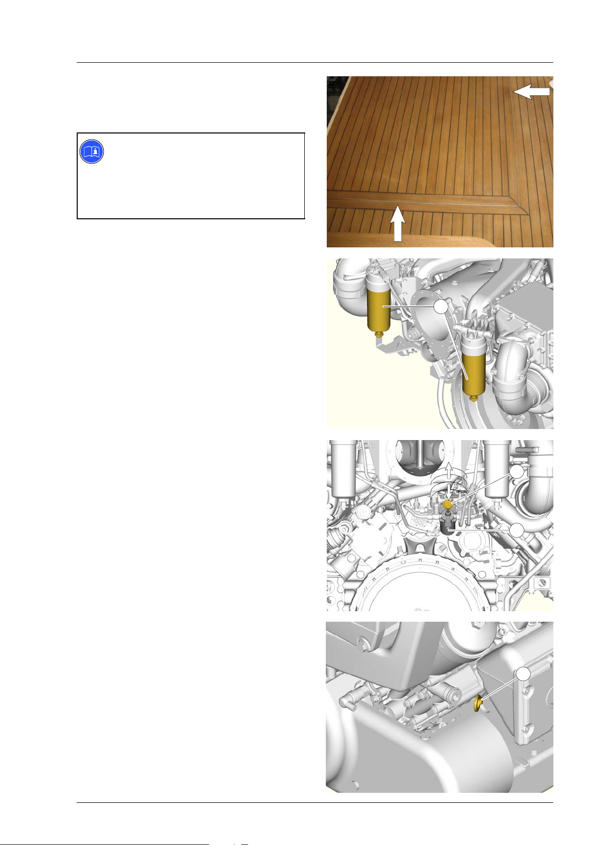
Accessibility of engine in engine room
When installing the engine, care must be taken to
ensure there is adequate space to perform the
regular maintenance work specified in the
maintenance schedule.
Note:
Advantages of easy access:
D High engine reliability due to easy
inspection and maintenance work
D Lower service costs due to reduced
time outlays
D Removable decking or hatch to facilitate the
lifting out of the engines in the event of repair.
It must be possible to carry out the following tasks
in the engine room on the engine and gearbox
without restriction:
D Fuel filter replacement À
D Servicing the fuel pre−filter / water separator
(not illustrated)
D Actuating the hand pump on the fuel delivery
pump Á and venting of the fuel system
D Servicing the fuel prefilter Â
(description in the Operating Instructions)
1
2
3
D Checking the lube oil level Ã, refilling / topping
up with lube oil
(description in the Operating Instructions)
4
13
Page 16
Accessibility of engine in engine room
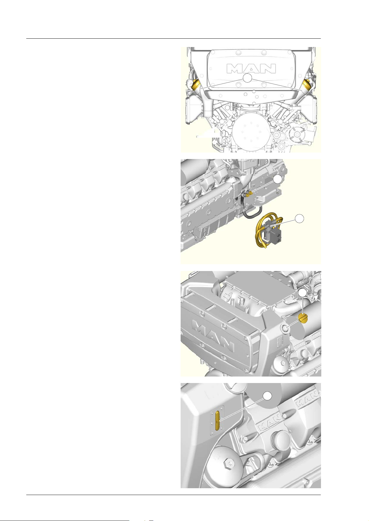
D Changing the oil filters Ä
(description in the Operating Instructions)
D Pumping off and filling of engine and gearbox
oil
(description in the Operating Instructions)
An oil drain for the engine and gearbox Å can
be supplied optionally (fitted left and right). An
electrical oil suction removal and filling pump Æ
can be connected via quick−release couplings.
5
6
7
D Filling the coolant
(description in the Operating Instructions)
Height of the deck above the filling cover Ç:
H=500 mm (recommended)
D Checking the coolant level È
(description in the Operating Instructions)
8
9
14
Page 17
Accessibility of engine in engine room
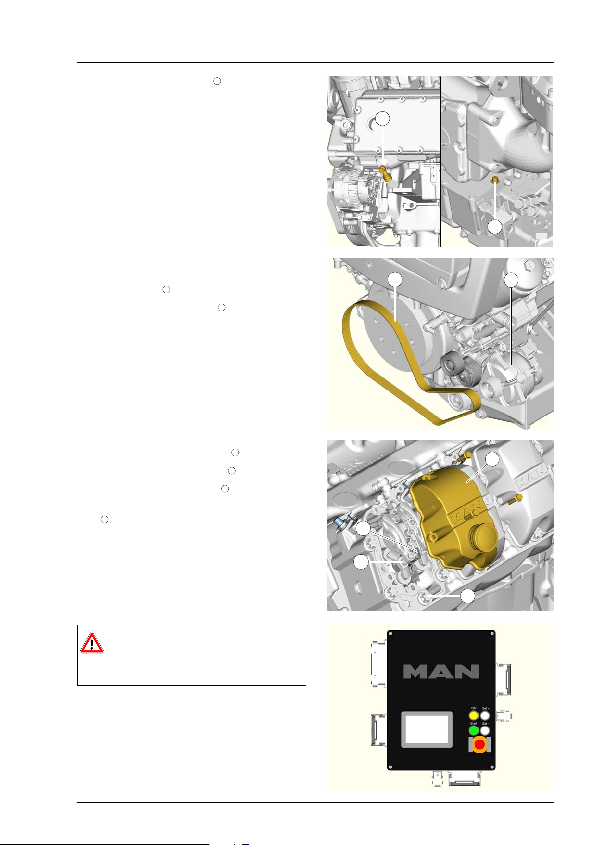
D Draining the coolant É and
(Description in the Operating Instructions)
D Maintenance of the plate−core heat exchanger
D Replacing belts
D Replacing starter, alternator 13 And coolant
pump
D Visual inspection and retightening of bolts and
hose connections
Distance to bulkhead: D=350 mm
12
11
10
12
11
13
Removing the cylinder head cover 14 to
D Adjustment of valve clearance
D Replacement of the injectors
Loosening and removal of the cylinder head
17
bolts
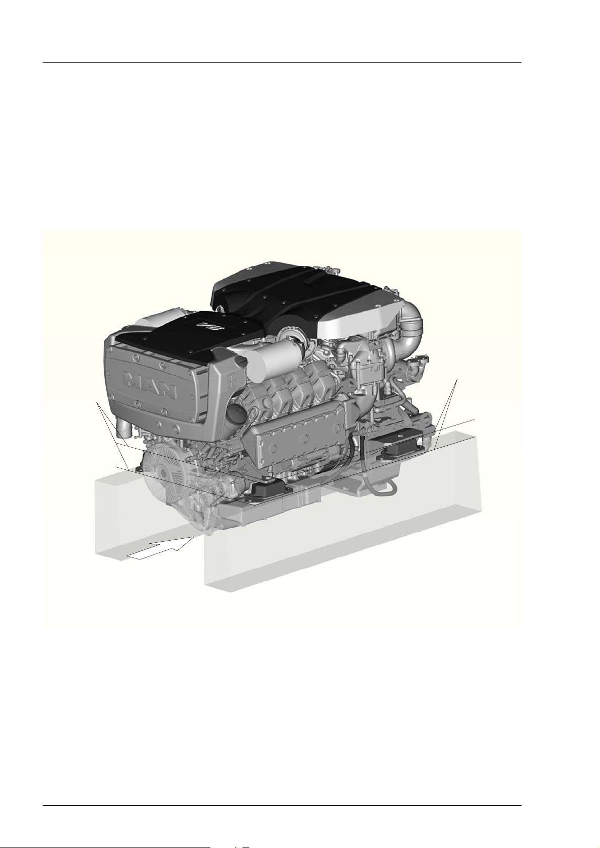
Danger:
The red emergency stop button on the
terminal box must be quickly and easily
accessible!
16
15
14
15
16
17
15
Page 18
Engine foundation
Requirements of engine foundation
D The engine foundation in the ship must be designed to absorb propeller thrust in both directions and
transmit it to the hull.
D The weight of the drive line and all of the dynamic forces caused by rough seas must be safely
absorbed.
D Hull torsion caused by motion of the sea and load must not be transmitted to the engine. The contact
area between the engine foundation and the hull should be as large as possible.
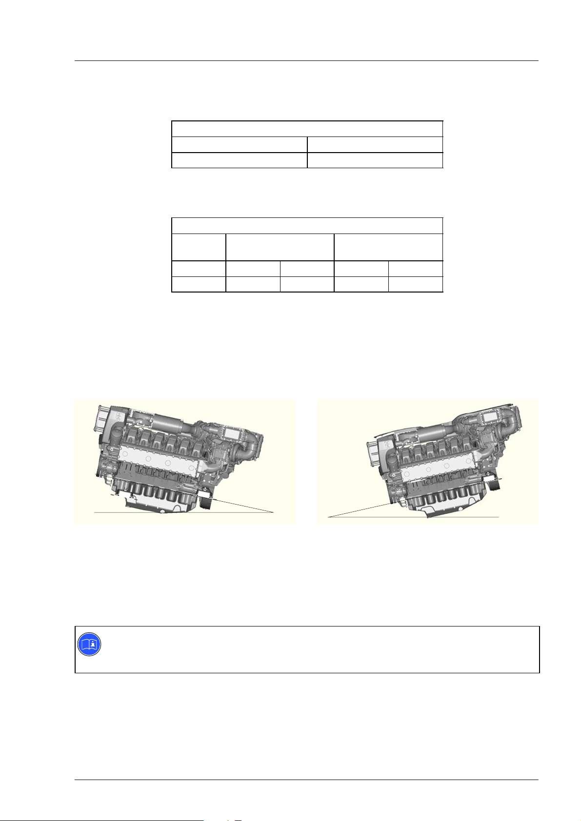
D The engine foundation must run parallel with the lower edge of the engine base, so that the resilient
engine mounts are not tilted. Engines must not be mounted rigid to the foundation.
Parallel
Accessibility
to underside of engine
Parallel
16
Page 19
Engine foundation
Engine weight
The weights of the engines (without gearbox) are given in the following table:
Engine weight (dry, without gearbox) in kg
V8−1200 1875
V12−1800 2365
The weights are based on the engine without lube oil and coolant. To determine the weight of the engine
ready for operation, the weight of the lube oil and coolant must be added.
Weights of the filling capacities
Engine
model
V8−1200 62 litres 56 kg 85 litres 90 kg
V12−1800 92 litres 83 kg 113 litres 120 kg
Lube oil Coolant
Maximum permitted angle of inclination for engine
If the engine is to be installed at an inclination on its longitudinal axis, the maximum permitted angle of
inclination must not be exceeded. The max. permitted angle of inclination is the largest angle that can be
expected when the ship is underway, i.e. installation inclination plus max. trim angle of the ship.
α
α=Angle at flywheel end
Engine model Oil pan (part no.) α β
V8−1200 51.05801−5774 20_ 5_
V12−1800 51.05801−5766 20_ 5_
β=Angle at free end
β
Note:
An angle β of 5_ as compared to the side opposite the flywheel may only occur during engine
operation. The installation angle as compared to the side opposite the flywheel is 0_
17
Page 20

Engine mounting
Choosing suitable resilient mounts
The resilient mounts prevent the transfer of engine vibrations to the engine foundation and ship’s hull.
Due to the design of the engine with respect to:
− Total mass
− Centre of gravity of engine
− Distribution of forces to the engine bases
Several requirements have already been established for the design of the resilient engine mounts.
Depending on the arrangement of engine and gearbox (engine with flange mounted gearbox or a free−standing engine and gear box) and the alignment thereof, the following points are also to be taken into
account:
− Propeller force transferred to the engine foundation for engines with flange mounted gearboxes
− Easy height adjustment of the mounts
Due to these various requirements, the resilient mounts must be carefully adapted.
For this reason MAN has developed resilient mounts that are adapted in their design and their shore
hardness to the different types of drive lines.
The following pages gives the assignment of the different resilient mounts to the arrangement of the
engines and gearboxes and detailed information about the mounts.
The resilient mounts are included in the delivery depending on the order. The resilient mounts should
always be used. In no case should the engine be installed on the foundation without them.
Note:
The resilient engine mounts cannot compensate for vibrations caused by inadequate alignment of
the drive line or by vibrations from the propeller.
18
Page 21
Engine mounting
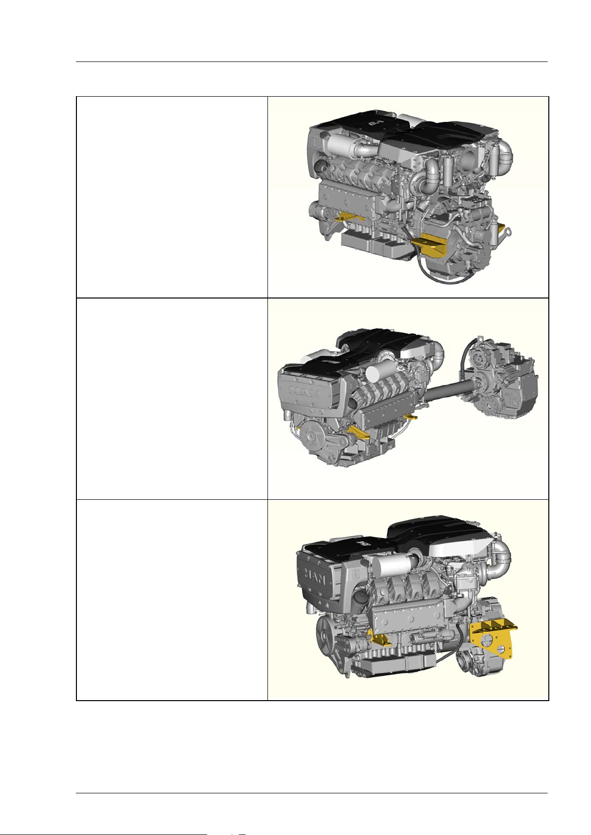
Overview of the possible arrangements of the engine and gearbox
Engine with flange mounted gearbox:
This figure shows a V8−1200 (example)
with a flange mounted gearbox. The
engine and gearbox brackets are
installed.
The corresponding resilient engine and
gearbox mounts are described on page
20 (for dimensions and drilling pattern
see installation drawing).
Engine with free−standing gearbox:
The figure shows a V12−1800 (example)
with a free−standing gearbox. The engine
brackets are installed.
The corresponding resilient engine
mounts are described on page 20 (for
dimensions and drilling pattern see
installation drawing).
Engines with integral V−gearbox:
The figure shows a V8−1200 with an
integral V−gearbox. The engine and
gearbox brackets are installed.
The corresponding resilient engine and
gearbox mounts are described on
page 21 (for dimensions and drilling
pattern see installation drawing).
19
Page 22
Engine mounting
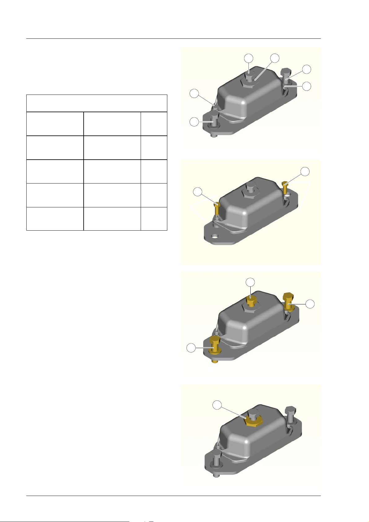
Resilient engine and gearbox mounts
À Mounting bolt for engine base M 20
Á Height adjustment
 Mounting bolts M 20, property class 8.8
à Shipping lock bolts
Assignment of the resilient mounts
to the engines and gearboxes
Engine model /
Gearbox
arrangement
V8−1200 with
flange mounted
gearbox
V8−1200 with
free−standing
gearbox
V12−1800 with
flange mounted
gearbox
V12−1800 with
free−standing
gearbox
MAN
part number
51.96210−7052 60
51.96210−7052 60
51.96210−7050 70
51.96210−7050 70
Shore
hard‐
ness
1
2
3
4
4
3
4
4
The installation drawings have information on the
dimensions of the mounts and the drilling pattern
for the foundation.
Installation of the mounts
D Place drive line with mounts on foundation.
D Remove shipping locks Ã.
D Tighten mount bolts  to 360 Nm.
D Tighten mounting bolts M 20 À to 300 Nm.
D The height of the mounts can be adjusted up to
max. 10 mm Á. The height adjustment can be
made with the supplied open end wrench (size
50). Try not to use the entire range on the
height adjustment so as to have room for
adjustments later. Large difference in heights
between the mounts can be compensated for
by using shims.
1
3
3
2
20
Page 23
Engine mounting
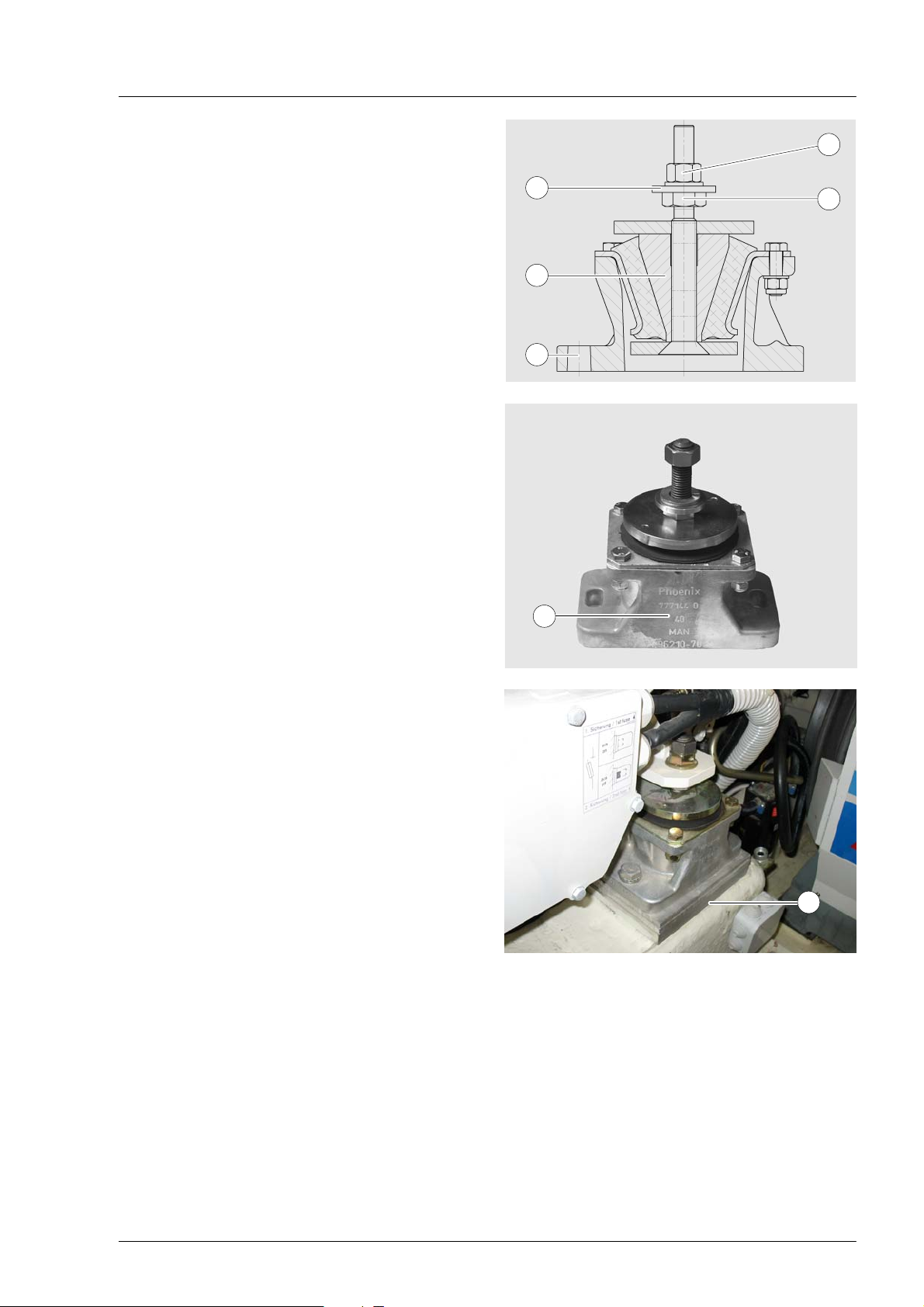
Resilient cone engine and gearbox
mounts for V8−1200 with integral
V−gearbox
À Mounting nut for engine base M20
Á Height adjustment
 Elongated hole for mounting bolts M18
à Cone mount
Ä Supporting disk for engine base
Å Designation of the mount according to Shore
hardness
1
5
2
4
The installation drawings have information on the
dimensions of the mounts and the drilling pattern
for the foundation.
Installation of the mounts
D Place engine with mounts onto foundation.
D Align the drive train after allowing the mounts to
settle for 48 hours, see page 29.
D Tighten mount bolts  to 260 Nm.
D Tighten mounting bolts M20 À.
D The height of the mounts can be adjusted up to
max. 10 mm. Try not to use the entire range on
the height adjustment so as to have room for
adjustments later. Large difference in heights
between the mounts can be compensated for
by using shims.
3
6
21
7
Page 24

Engine room ventilation
Heating of the engine room
During operation, each engine transfers heat from its own hot surfaces into the air in the engine room
(convection), in a similar fashion to a radiator heating a room in a building. In addition, but to a much lesser
extent, radiated heat dissipates to the surroundings (radiant heat).
Both of these effects can heat up the engine room to such an extent, that temperature−sensitive
components (e.g. the electronics) can malfunction.
Temperature in the engine room
Caution:
The following equation provides a good rule of thumb for adequate engine room ventilation:
Engine room temperature = Ambient temperature + 15°C (max. 20°C)
Measured at the front and back of the engine room and at the air filters.
The max. permissible engine room temperature is 60_C.
The temperature in the engine room is essentially dependent on the following boundary conditions:
Outside air temperature
The outside air temperature depends on the climate in the area of operation of the ship and the prevailing
weather conditions. In the Mediterranean Sea area air temperatures of up to 40°C are to be expected and
in the Persian Golf up to 50°C can be reached.
Engine operating conditions
1) Maximum speed / cruising speed of the ship
Naturally, at full−load and high power outputs, the temperature of critical components (charge air pipes,
compressor housing, exhaust manifold) is at its highest and thus the heat output is at a maximum.
However, this effect is compensated by the high combustion air requirement of the engines and that of
the associated high rate of air exchange in the engine room.
Example: Two engines V12 − 1800 at 2300 rpm and full load with 2 x 6300 m3/h demand for combustion
air, corresponding to 3.5 m3/s. A typical engine room air volume of 50 m3 is thus replaced every 15
seconds. With adequately dimensioned air inlets and outlets the engine room temperature may not vary
significantly from that of the outside air.
2) Reduction of the maximum speed to crawling speed (e.g. to negotiate canals, waterways with speed
restrictions)
At low speeds and loads, the combustion air demand of the engines and thus the inflow of fresh air into
the engine room is very significantly reduced.
Example: Two engines V12 − 1800 with 2 x 750 m3/h combustion air requirement, corresponding to
0.20 m3/s at 1000 rpm and operation on the propellor curve.
The volume of air in the engine room is no longer replaced fast enough by external air flowing through
and can therefore quickly heat up. In addition, the hot engine components that were under full load
(charge air pipes, crankcase, oil pan) give up additional heat in the engine room.
In this operating phase it is thus necessary to provide forced air ventilation by means of fans.
22
Page 25
Engine room ventilation
Air requirement and air pressure in engine room
The air admission into the engine room is ensured by the cross−section and the design of the air inlet
openings.
Air requirement per engine
Engine model Power kW (HP) Speed rpm Air requirement m3/ h
V 8−1200 882 (1200) 2300 4100
V 12−1800 1324 (1800) 2300 6300
The air requirements given in the table represent the combustion air requirement for each engine.
The air intake openings in the engine room have to be dimensioned to accept this volumetric flow.
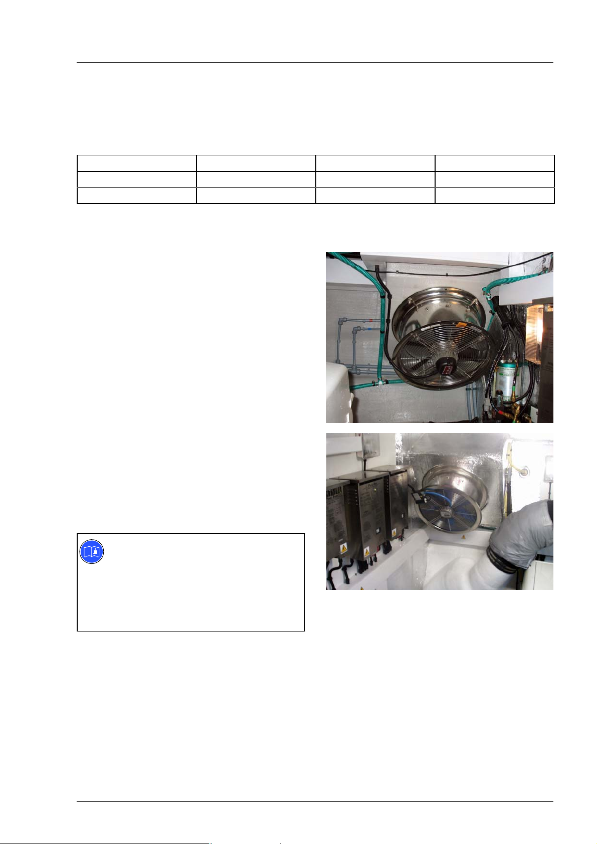
Fans
Fans with large dimensions are required to ensure
that the entire engine room has a thorough
circulation of fresh air.
The following criteria will help you in selecting
effective fans:
1. Fans with
a 24V constant voltage power supply,
= 160 mm to 300 mm
2. Fans with
an alternating voltage supply from the ship’s
generator, 240V,
= 150 mm to 450 mm
Small fans attached to corrugated hoses are not
suitable as they do not provide a sufficient flow
rate and only guarantee a supply of fresh air in
their immediate vicinity.
Suction ventilators are recommended; these suck
the warm air out of the engine room so that fresh
air can flow in through the air inlet openings.
Note:
If the air pressure in the engine room
exceeds the surrounding atmospheric
pressure, vapours, oil mist, etc. can make
their way into the living quarters
accommodation on the ship and lead to
bad odours.
23
Page 26
Air ducting, general
Engine room ventilation
The openings for the inlet and outlet of air are to
be arranged such that a purging affect is created,
i.e. the whole engine room is provided with a flow
of air.
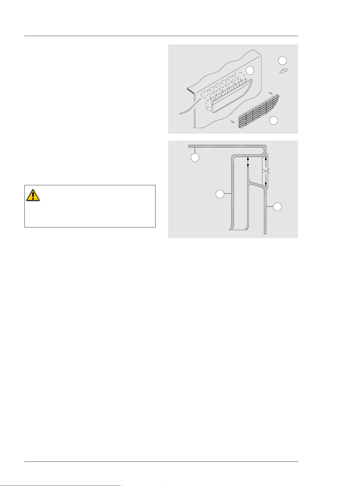
Fresh air inlet to engine room
Fresh air should enter along the side of the hull at
as high a position as possible ahead of the engine
room.
À Direction of travel
Á Hoses to engine room
 Air baffle
It is possible to optimise the volume of the air flow
by shaping the air supply duct to optimum flow
effect and by utilising the air stream produced from
forward motion.
Caution:
Water spray and splash water must not be
allowed to reach the engines!
Water ingress would lead to the total loss
of the engine!
1
2
3
4
A
A
5
6
A Free cross−section
à Deck
Ä Air duct
Å Side of ship
The free cross−section A of the air inlet is related
to the narrowest point of the complete air supply
route. It is dimensioned according to the air
requirement of the engines in accordance with the
table on page 23.
Air should enter the engine room at as low a point
as possible between the ship’s sides and the
engines.
Air outlet from the engine room
The air outlet should be located opposite the inlet,
i.e. at the back of the engine room and as high as
possible.
24
Page 27
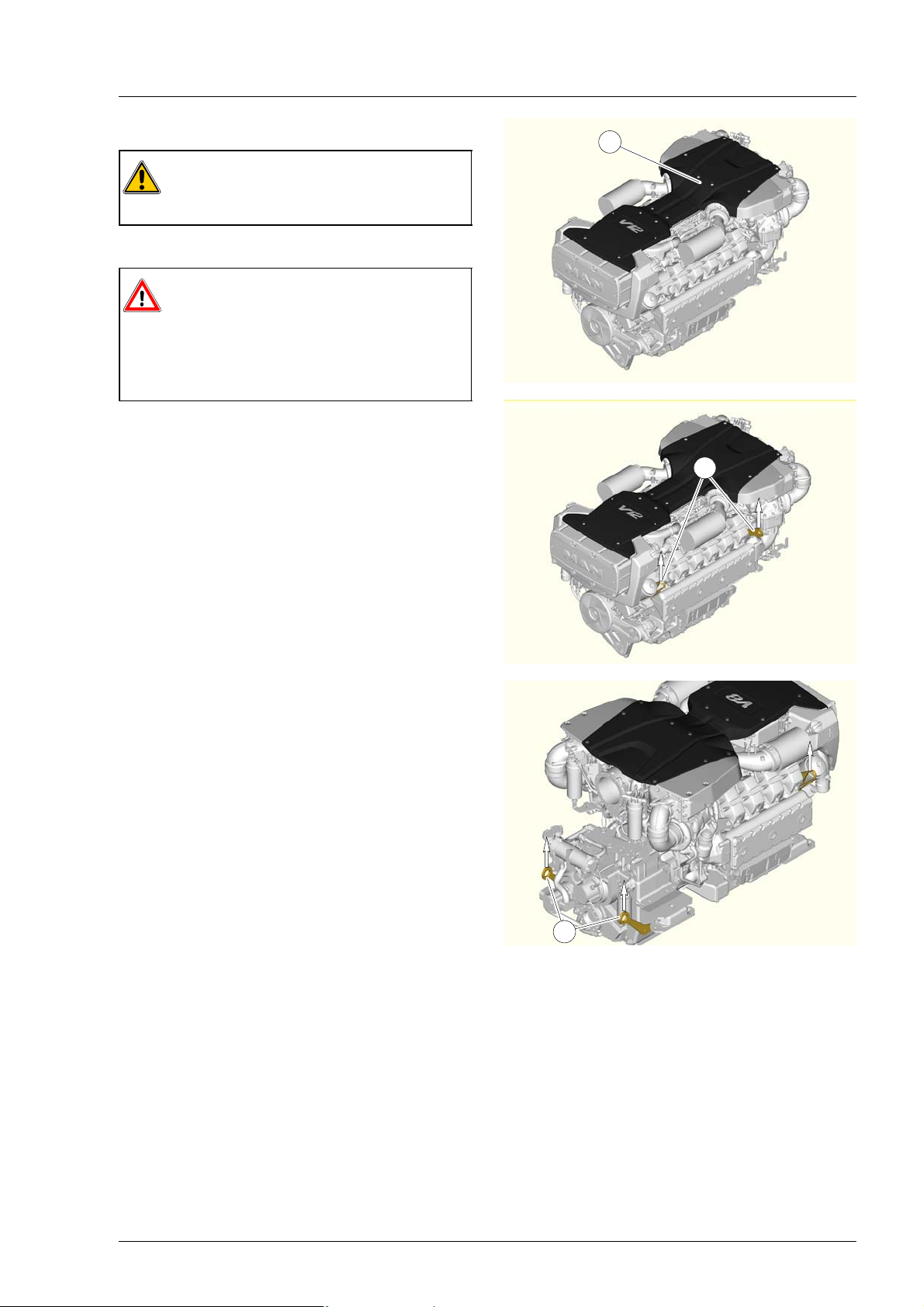
Crane transport of the engine
Transporting drive line onto ship
Caution:
When working on the engine make sure to
not step on the engine cover À.
Use crane lifting equipment to lift engine.
Danger:
Using unsuitable lifting equipment that is
not strong enough for the load may result
in serious accidents/injury!
Make sure ropes and chains do not pull
crookedly on the crane hooks.
There are 4 crane hook lugs Á on the engine to be
used when lifting the engine without the gearbox
attached.
When lifting the engine with the gearbox attached,
use the engine’s two front crane hook lugs and the
other two on the gearbox Â.
1
2
25
3
Page 28
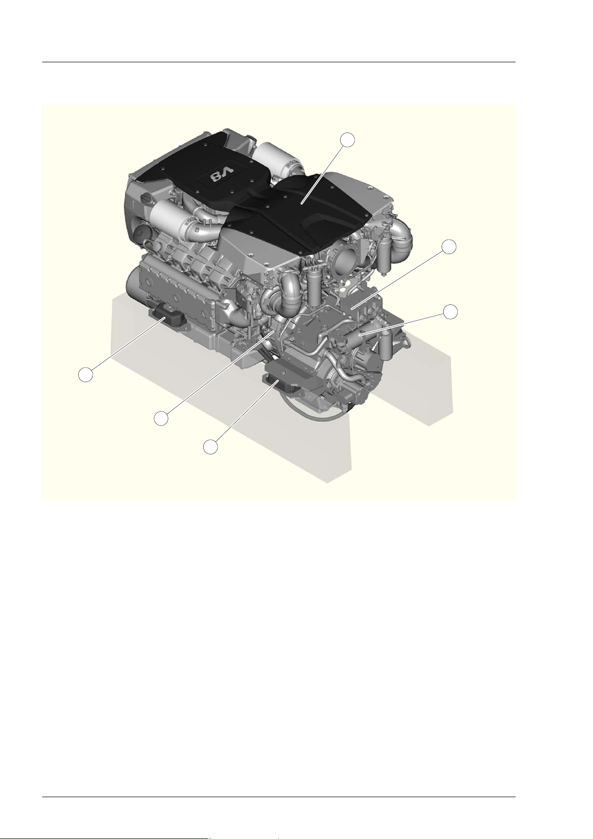
Flange mounting a gearbox
Drive line consisting of the engine and flange−mounted gearbox
1
2
3
6
5
4
À Engine (in this case V8−1200)
Á Reversing gearbox flanged mounted at flywheel housing
 Gearbox cooler, see page 48
à Resilient gearbox mount, see page 20
Ä Flywheel housing, see page 27, 28
Å Resilient engine mount, see page 20
Torsional−vibration analysis
The forces of gas and inertia from the engine can cause vibration of the entire drive line. In order to
determine the resonance in terms of position and strength and to avoid overstressing, a torsional−vibration
analysis is required.
This can be carried out by MAN for a fee. The requisite data are to be collected during the project phase in
the form of a questionnaire − "Questionnaire on torsional vibration calculation for ship’s drive line".
26
Page 29

Flange mounting a gearbox
Flywheel and flywheel housing
The following applies for all V8 and V12 engines:
À Flywheel with I = 1.9 kgm2 for flange mounting
a gearbox
Á Flywheel housing with SAE1 connection
Note:
To carry out an exact installation
inspection, request an installation drawing
showing detailed dimensions for the
flywheel or flywheel housing.
Resilient coupling
A torsionally resilient coupling à is to be provided
between the engine and the gearbox.
This has the function of decoupling vibrations
between the engine and the drive train (gearbox,
propeller shaft and propeller). In this way, high
frequency vibrations created by the ignition cycle is
restricted to the engine crankshaft.
Furthermore, the transfer of low frequency
vibrations of the drive train to the engine is
prevented.
Installation of the coupling to the flywheel
The dimensions of the flywheel À and type of
bolted connections  for installing the coupling can
be found in the installation drawing.
1
2
3
4
27
Page 30

Flange mounting a gearbox
Flange mounting the gearbox to the
flywheel housing
The dimensions of the flywheel housing À and
type of bolted connections for installing the
gearbox can be found in the installation drawing.
Note:
Tightening torques for screws,
see page 79
Crankshaft axial play
Caution:
The designed crankshaft axial play of the
engines must not in any event be reduced
by the flange−mounting of couplings or
other components.
Therefore it is absolutely necessary to measure
the crankshaft axial play before and after the
installation of components Á using a magnetic
mounting fixture with dial indicator Â. If both
measurements do not match, or if the crankshaft
bounces back after being pressed, check the
installation.
Carry out the measurement as follows:
D Remove the V−belt guard
D Secure the magnetic base of the dial gauge on
the engine base
D Attach dial gauge with pre−tension on the
crankshaft
D Push the crankshaft to the end position in the
direction of the flywheel housing.
D Set the dial gauge to zero
D Pull the crankshaft to the end position in the
direction of the dial gauge and read off the
difference.
Engines Crankshaft axial play
V8−1200 0.20−0.40 mm
V12−1800 0.20−0.40 mm
1
2
3
28
Page 31

Aligning an engine with flange−mounted gearbox
Note:
The mounts are pre−compressed at the factory by the shipping locks. For this reason it is not
necessary to preload the resilient mounts before the alignment.
Provisionally aligning drive line
D Place the drive line and the resilient mounts
onto the engine foundation using suitable crane
lifting equipment.
D Raise the propeller shaft by hand at the
coupling flange as far as possible.
Half the angle between the highest and lowest
positions of the coupling flange provides the
correct height for the gearbox output flange.
This ensures that the propeller shaft can be
correctly centred.
Note:
A resilient propeller shaft coupling between
gearbox output flange and propeller shaft
flange compensates minor offset and
reduces vibrations.
D Align gearbox output flange and propeller shaft
flange flat with the aid of suitable surfaces.
D Adjust the height À of the engine mounts Á. In
so doing, ensure that the mounts are equally
compressed on both sides of the engine.
Caution:
The max. height adjustment of all mounts
is 10 mm.
This adjustment height must not be
exceeded. Larger differences in height
must be compensated for with metal
shims.
The less the height is adjusted, the more
room for later adjustments.
1
2
29
Page 32

Aligning an engine with flange−mounted gearbox
Aligning drive line
The drive line (engine and gearbox) and the propeller shaft must be aligned so that the radial offset and
angle offset of all the components are within the specified tolerances.
Caution:
In order to avoid damage by vibrations and oscillations, the alignment of the drive line must be
checked annually or after approx. 3000 operating hours and if necessary adjusted.
Parallelism of flanges
Check that shafts are flush in advance
D Using straightedge  at several points, check
whether gearbox output flange À and propeller
shaft flange Á are flush in relation to each
other.
Check for parallelism of flanges
D Join propeller shaft flange and gearbox output
flange together
D Slide feeler gauge à with a 0.5 mm blade
between the flanges, screw in a coupling bolt
and tighten slightly
D Pull out the 0.5 mm blade
D Check the gap dimension all round at 90°, 180°
and 270° with 0.58 mm and 0.42 mm blades
(the tolerance must not exceed 0.08 mm)
D Remove the bolt and apply a marking to the
gearbox output flange
D Rotate the gearbox output flange through 90°,
180° and 270° and repeat the check
If the measurement produces a reading of more
than 0.125 mm, then the propeller shaft flange is
running with excessive lateral runout (wobble).
3
1 2
4
30
Page 33

Aligning an engine with flange−mounted gearbox
Checking gearbox output and propeller shaft
for radial and angle offset
Radial offset means that the centre lines of
2 associated flanges are actually parallel, but are
offset laterally in relation to each other.
À Flange (e.g. gearbox output)
Á Flange (e.g. propeller shaft)
Radial offset: X = max. 0.5 mm
Testing for radial offset: The dial indicator is
installed in one of the shaft ends. Connect both
flanges but not fully. To do this, screw in one bolt.
The face sides of the flanges must not touch.
The check is repeated four times with an angular
spacing of 90° between each check.
The display must not deviate by more than
2 x 0.5 mm = 1 mm.
1
2
x
Angle offset means that the centre lines of 2
associated flanges are not parallel.
À Flange (e.g. gearbox output)
Á Flange (e.g. propeller shaft)
 Angle offset
Angle offset: max. 0.1 mm
with reference to 200 mm flange diameter
Checking the angle offset: The dial gauge is
attached to one of the shaft ends. Connect the two
flanges by turning as far as they will go without
forcing them. To do this tighten a screw. However,
the faces of the flanges may not come into
contact.
The check is repeated four times with an angular
spacing of 90° between each check.
The maximum permissible angle offset may not be
exceeded at any measuring point.
Caution:
The alignment of the drive line must be
checked after the ship has been launched.
If readjustment is necessary, make sure
that all the mounts have a uniform bearing
function.
x
1 2
3
x+max.0.1mm
31
Page 34

Transmission of power by propshafts
Drive line consisting of engine, highly resilient coupling, propeller shaft and
gearbox
1
5
2
4
3
Drive line consisting of engine, resilient coupling with flange bearing, propeller
shaft and gearbox
1
5
2
4
3
32
Page 35

Transmission of power by propshafts
Arrangement of the drive line
The drive line consists of the engine and the free standing (not flange mounted) gearbox. This allows the
engine and gearbox to be installed at different positions (usually in V−Drive design), so that the power
transmission from the engine to the gear box is made through a propeller shaft. For this type
has developed solutions for the selection of the coupling and guidelines for the alignment of the drive line.
The goal here was to:
D Avoid damage caused by vibrations at the engine, gearbox, resilient coupling and propeller shaft
D Avoid the transfer of vibrations into the engine foundation and thus
therefore increase the comfort on board
There are two ways to connect a propeller shaft to the engine:
1. Engine power is transferred through a highly resilient coupling (figure at top left).
The highly resilient coupling connected to the engine’s flywheel allows working angles of max. 3°.
À Engine
Á Resilient engine mounts
 Highly resilient coupling, see page 34
à Free−standing gearbox
Ä Propeller shaft, see page 35
avoid vibrations of the ship and
of setup MAN
2. Engine power is transferred through a resilient coupling with a flange bearing (figure at bottom left).
This concept requires more construction space due to the flange bearing, but allows a working angle of
up to 9°.
À Engine
Á Resilient engine mounts
 Resilient coupling with flanged bearing, see page 34
à Free−standing gearbox
Ä Propeller shaft, see page 35
Torsional−vibration analysis
The forces of gas and inertia from the engine can cause vibration of the entire drive line. In order to
determine the resonance in terms of position and strength and to avoid overstressing, a torsional−vibration
analysis is required.
This can be carried out by MAN for a fee. The requisite data are to be collected during the project phase in
the form of a questionnaire − "Questionnaire on torsional vibration calculation for ship’s drive line".
33
Page 36

Transmission of power by propshafts
Flywheels
Note:
To carry out an exact installation
inspection, request an installation drawing
showing detailed dimensions for the
flywheel or flywheel housing.
À Flywheel with I = 1.1 kgm2 for the installation of
a highly resilient coupling
Á Flywheel with I = 1.9 kgm2 for the installation of
a resilient coupling with flanged bearing
1
Highly resilient coupling
The highly resilient coupling  is installed at the
engine’s flywheel. The coupling can only be
installed if the engine is equipped with the
corresponding flywheel for propeller shaft
couplings À.
It allows permissible propeller shaft−working angles
ß1, ß2 of 3°.
For interface dimensions see installation drawing.
Resilient coupling with flange bearing
2
3
The resilient coupling with flange bearing à is
installed on the engine at the factory. The coupling
can only be installed if the engine is equipped with
the corresponding flywheel Á.
It allows permissible propeller shaft−working angles
ß1, ß2 of 9°.
For interface dimensions see installation drawing.
Weight: 128 kg
4
34
Page 37

Transmission of power by propshafts
The working angle of a propeller shaft
The working angle ß of a propeller shaft is the
angle between the propeller shaft and the input /
output shaft.
Basic guidelines for installing propeller
shafts
When a single cardan joint, universal joint or ball
joint is rotated while bent, an irregular motion
occurs at the output end.
b
1
b
2
This irregular motion can be compensated for by
connecting two joints to one propeller shaft. For
the complete compensation of the irregular
motions, the following requirements must be met:
D Identical running angles at both joints (ß1=ß2)
D Both inner joint forks must lie in a plane
D Input and output shafts must also lie in one
plane
Propeller shaft arrangement in Z−Form
Propeller shaft arrangement in W−Form
Exception:
In the case of a spatially−angled propeller shaft,
the input and output shafts do not lie in one plane.
To achieve a steady output motion, the inside
propeller shaft forks must be twisted against one
another so that they both lie within the angled
plane produced by their joints. In addition, the
spatial working angles must be the same.
35
Page 38

Transmission of power by propshafts
Aligning engine and gearbox
Alignment type Permitted tolerances
1 Max. angle per joint See page 34
2 Input and output angles ß
ß
1,
2
Difference jß
ß2j 0.5°
1 −
(=working angles) must be the
same
3 Engine, propeller shaft and gearbox
must be arranged in a line in the
<1 %o
i.e. over 500 mm measured length 0.5 mm
top view
4 The inner fork heads must lie in a
<1°
plane
5 Static offset of engine to gearbox
<1 mm
longitudinal axis (in the plan view)
Auxiliary equipment consisting of two alignment rods can be used to obtain the same working angle for a
V-configuration.
Such auxiliary equipment is illustrated below.
For the dimensions given this equipment can be used for propeller shafts with lengths of
L
= 700 to 1300 mm. Shorter or longer propeller shafts require shorter or longer rods A.
z
A
Procedure: Mount alignment rods in place of the propeller shaft. Both parts must be of the same length.
Align engine or gear box so that the tips of the alignment rods meet. Remove the auxiliary equipment and
mount the propeller shafts.
36
Page 39

Transmission of power by propshafts
Installing propeller shafts
When connecting the propeller shaft halves, make sure that the markings (arrows) on the splined shaft and
the splined hub face each other.
Caution:
Incorrectly assembled propeller shafts will not compensate for irregular motions, but rather
increase it. This causes vibrations in the drivetrain. Furthermore, the joints and splined sections
may be damaged.
The propeller shafts are to be arranged so that the splined section is protected from dirt and moisture.
Usually what this mean is that they are to be installed as per the following drawings, where the profile seals
are pointed down so that any splash water can flow away from the splined section.
The propeller shafts must not be separated at the splined section and must not be swapped with each
other. Otherwise the balance of the shafts will be considerably affected. For this reason the balance
weights are also not to be removed.
37
Page 40

Diagram of the charging
Combustion air system and charging
À Air filter
Á Turbocharger, high compression stage
 Intercooler
The diagram shows the combustion air ducting on the V8−1200. The design is identical for V12−1800.
There are two stages of turbocharging whereby the combustion air is cooled after each stage. Each
cylinder bank has one low compression stage turbocharger, one intercooler and one high compression
stage turbocharger.
After passing through the air filter, the combustion air is pre−compressed by the low compression stage
turbocharger and cooled by the intercoolers. The high compression stage turbocharger compresses the
combustion air to the final pressure. Before the air reaches the cylinders, the air is cooled in the charge air
cooler to a temperature of approx. 50°C. The waste gates limit the amount of combustion air flow and
prevents an overload of the engine.
Both the intercooler and the charge air cooler are supplied with sea water.
Caution:
The proper operation of the charge air cooler and the intercooler can only be ensured if sufficient
sea water is supplied, see chapter “Cooling system” page 45.
à Turbocharger, low compression stage
Ä Boost pressure control valve
Å Charge air cooler
38
Page 41

Combustion air system and charging
Combustion air requirement
In order to burn fuel completely and thereby achieve full power, the engine requires an adequate supply of
fresh air, the volume of which can be determined from the technical data provided in the appendix to this
manual.
Air filters
Caution:
If any dust producing work is to be
performed on the ship after the engine has
been installed, please take measures to
protect the air filters from this dust.
Vacuum downstream of air filter
The maximum permitted intake vacuum at
maximum power and rated engine speed is:
V8−1200
in new condition: 35 mbar
in soiled condition: 70 mbar
V12−1800
in new condition: 70 mbar
in soiled condition: 90 mbar
Caution:
If this value is exceeded, check ventilation
of the engine room, see page 22.
39
Page 42

Exhaust system
Basic construction elements
Danger:
The exhaust system must be completely
gastight in order to fully exclude the
danger of poisoning.
Under no circumstances may water be allowed to
ingress the engine via the exhaust gas system. In
the case of a low installation of the engine and
exhaust gas outlet, just above or below the water
line, a bend must be built into the pipe, with a
subsequent falling exhaust gas outlet ("swan
layout") À. This is to prevent water ingressing the
engine when manoeuvring astern.
Caution:
If sea water ingresses the engine, it will
result in a total write−off that is not covered
by the MAN warranty.
neck
1
It is not permissible to provide a single common
exhaust system for several engines. In the case if
multi−engine layouts a separate exhaust system for
each engine is obligatory, so that with one engine
running, no exhaust gas can enter the other
engine/s.
Securing exhaust system
Caution:
Secure and support the exhaust pipes so
that no forces act on the turbochargers.
How the exhaust system is secured depends on its
basic design.
If the exhaust system is connected to the engine
by way of heat−resistant hoses, the supports can
be attached to the engine and gearbox feet
(Á and Â).
If the exhaust system is connected to the engine
by way of bellow expansion joints, the exhaust
system must be suspended from vertically
adjustable brackets Ã.
2
3
40
4
Page 43

Exhaust gas outlet on the engine
Exhaust system
On both the V8−1200 and V12−1800 both banks of
cylinders are routed to a central exhaust gas
outlet.
On both types, exhaust gas manifolds can be
provided either for an exhaust gas outlet to the
rear À or upwards Á.
The dimensions of the flange for the connection of
the boat−side exhaust gas system are shown on
the installation drawing.
Connecting exhaust system to engine
Install resilient connecting elements between
engine and exhaust system which permit engine
movement resulting from the resilient engine
mounting and isolate the engine vibrationally from
the exhaust system.
Either heat−resistant hoses (corrugated hoses
made of silicone) or bellow expansion joints can be
used for this purpose.
Installing exhaust bellow expansion joint
1
2
Exhaust pipe bellows  prevent the transfer of
vibration from the engine to the exhaust gas
system and compensate for expansion of the
exhaust pipe due to heating.
Installing the exhaust gas bellows under pre−tensile load.
Pre−tensile loading means that before screwing on
the bellows, the distance X between the flange of
the bellows and the mating flange of the
downstream exhaust pipe à should be 10−15mm.
For flange hole pattern and dimensions see
installation drawing.
3
4
x
41
Page 44

Exhaust system
Injection of sea water into exhaust
system
After emerging from the heat exchanger, sea water
is injected into the exhaust pipe and mixed with the
exhaust gas.
Schematic drawing of sea water injection
(example)
À Sea water
Á Exhaust gas
 Baffles with obtuse angle of incidence for water
flow
à Baffles with acute angle of incidence for water
flow
4
2
1
Silicone hose Ä after sea water injection.
3
5
42
Page 45

Exhaust system
Exhaust silencing
Exhaust silencing can be achieved either by
means of an exhaust outlet below the water line or
by installing exhaust silencers.
Exhaust outlet below water line
As well as noise damping, an exhaust outlet below
the water line normally gives rise to an increase in
exhaust backpressure.
A flow−optimised configuration of the exhaust
outlet can reduce this effect.
However, there must be no incidence of vacuum
pressure here.
Caution:
A vacuum at the exhaust outlet leads to
impermissible high turbocharger rpms and
is therefore not allowed.
If the exhaust outlet is located below the water
line, incorporate a bypass to the exhaust pipe with
an outlet above the water line.
If this bypass is omitted, there can be a build−up of
pressure in the exhaust system when the ship is
stationary or moving at low speed until this
pressure exceeds the water pressure below the
ship and then escapes abruptly, resulting in
intense vibrations.
Permitted exhaust back pressure
The exhaust backpressure must be measured
during commissioning.
Measuring points of the exhaust back pressure (À
or alternatively Á, M14x1.5) can be found on the
underside of the exhaust manifold at the engine.
It is the static pressure which is measured, i.e. the
measurement connection must be internally sealed
with the pipe wall. Measurements of the dynamic
pressure lead to incorrect results.
1 2
Permissible exhaust backpressure at full load and
rated rpm: 20−80 mbar
Caution:
Exceeding the permissible value leads to
an impermissible exhaust temperature and
to thermal loading, as well as to
inadequate engine power and considerable
smoke development.
43
Page 46

Exhaust system
Insulation of the exhaust pipe
(applies for both wet and dry exhaust systems)
Exhaust pipes must be carefully insulated using
fireproof material.
Danger:
Missing or unsuitable insulation can lead
to:
D Accidents with burns
D Fires in the engine room
D High engine room temperatures
Hot, non−insulated exhaust pipes heat up the
engine room considerably.
The quantity of heat emitted increases by the
surface temperature raised to the power of 4, e.g.
surface temperature increases by 20% − the
radiated heat produced is doubled.
Requirements on the insulation material:
− Flame retardant
− Fuel− and lubricant−impermeable
− The material must not release dust or fibres
into the atmosphere as these can be drawn
in by the engine
44
Page 47

Cooling system
Seawater cooling system
The seawater cooling system is used to cool the engine and the charge air cooling system. For full engine
power at the permissible thermal loads it is very important that the charge air cooling system has an
adequate supply of sea water.
The cooling system on all MAN engines is designed for seawater temperatures of up to 32°C (305 K).
1
2
3
4
7
6
À Expansion reservoir
Á Charge air cooler, high compression stage
 Seawater outlet
à Intercooler, low compression stage
Ä Seawater pump
Å Seawater inlet
Æ Connection of cool water supply to gearbox cooler
4
5
Note:
The connection for the cooling water return from the gearbox cooler is to be installed by the
shipyard on the cooling water pipe downstream from the seawater outlet Â.
45
Page 48

Cooling system
Seawater inlet
Sea water enters through a scoop À on the
underside of the hull.
In this way, the pressure created at the sea water
inlet while the ship is moving can be utilised to
supply the pump with sea water.
Scoop
Although the inlet cross−section of the scoop is
determined by the diameter of the sea water inlet
pipe, it should nevertheless be designed to be as
large as possible within the framework of these
limits.
In order to achieve a flow−optimised shape, the
entire scoop should be manufactured as a single
casting.
The sea water enters through a grille with large
openings between the bars Á. In order to assist
the inflow into the sea water inlet pipe to the
engine, the back of the scoop  must have a
round, flow−optimised shape so that no water
backpressure can inhibit the sea water supply.
1
3
2
In the case of two−part scoop designs, i.e.
separate grille à and sea water inlet line Ä, poor
arrangement of these two components will cause
water backpressure at the back of the scoop.
The same effect can arise in the case of one−part
scoops with rectangular grille designs.
Seawater inlet for jet drive
The water supply flow for the jet drive must not
hinder the seawater supply for the engine cooling
system.
5
46
4
Page 49

Seawater supply components
Cooling system
Sea valve
Ball valves which are bolted directly to the scoop
should be used as sea valves À .
These can be swiftly closed in an emergency (pipe
break).
In addition, the "Open / Closed" setting of the valve
can be immediately identified from the position of
the handle.
Seawater filter
The seawater filter Á should be equipped with a
sight glass, a removable cap and a removable filter
basket.
The following approximate values apply to the filter
basket:
− Mesh size max. 3 mm
− Surface approx. 10 times as large as the
inlet cross−section
Positioning of sea water filter:
If possible directly above the sea valve.
In any event the sea water filter must be situated
above the water level.
1
2
This allows the filter to be cleaned with the sea
valve open. Furthermore, with the sea valve open,
objects blocking the scoops can be removed
without having to lift the ship out of the water.
Seawater pipes to and from engine
The sea water lines (hoses) must be sufficiently
flexible to compensate movements of the engine
due to its resilient mounting.
47
Page 50

Seawater pump
Flow rate of the seawater pump Á:
Cooling system
Engine
model
V8−1200 570 1.4 −0.1
V12−1800 680 1.9 −0.1
Seawater inlet
The seawater filter line is connected to the intake
connection Á of the seawater pump. A hose is
used for this purpose with a diameter of 4 inches.
Seawater outlet
The ship−side piping is connected to the seawater
outlet Â. Seawater is frequently sprayed into the
exhaust system, see page 42. A hose with a 4 inch
diameter is used to connect to the ship−side piping.
Flow rate
Litre / min
Pressure
down−-
stream of
pump
bar
Pressure
upstream
of pump
bar
1
4
2
Measuring points for commissioning
For the commissioning process there are
measuring points à installed at the inlet and outlet
for the seawater (M14x1.5).
Gearbox oil cooler
Cooling water for the gearbox oil cooler is supplied
through the connection Ä on the seawater pump.
The gearbox oil cooler’s water supply is marked
with “out".
The connection for the cooling water return from
the gearbox cooler is to be installed by the
shipyard on the ship−side piping.
There are 2 possibilities for this:
1. Installation in the seawater outlet downstream
of engine
2. Installation in the seawater injection in the
exhaust system
4
3
5
48
Page 51

Cooling system
Choice of materials for pipework
Various metals may not be freely combined with each other. If “noble" and "non−noble" metals are
combined, the “non−noble" metal will corrode both of them due to bimetallic corrosion.
This process is accelerated still further in humid or even salty atmospheres.
The more non−noble a metal is, the more negative its
bimetallic voltage difference that wants to be balanced out when they are combined (direct contact or
conduction through water). The following lists metals according to their electric potential starting with the
"most noble" (platinum) down to the “most non−noble" (magnesium).
The further two metals are
apart in this list, the greater the problems to be expected by bimetallic corrosion.
“Nobel” Platinum
negatively charged. Two different metals have a
Titanium
Silver
Nickel
Cupro−nickel
Lead
Stainless steel
Tin bronze
Copper
Tin
Brass alloys
Ferronickel
Commissioning
Note:
Proof of an adequate sea water supply is a decrease in vacuum pressure in the inlet pipe with
increasing ship speed, ideally to overpressure.
D At standstill: 0.3 bar at set rated speed
D At maximum speed: 0.05 bar
If the vacuum pressure increases while the ship is moving, then seawater supply cannot be
ensured.
Low−alloy steels
Shipbuilding steel
Aluminium alloys
Zinc
"Non−noble" Magnesium
49
Page 52

Diagram of the fuel system
Fuel system
1
2 3
4
5
7
6
À Fuel system on engine
with hose connections for:
Á Fuel return
 Fuel supply
The fuel flows from the tank through the fuel prefilter with water separator Ä to the fuel system on the
engine À. Surplus fuel is returned back to the tank.
The following are important for proper engine operation: the installation of a fuel prefilter with water
separator Ä, see page 51, and the dimensions and spatial arrangement of the fuel system lines on the ship
side, see page 53.
Fuel system on ship
with:
à Fuel supply from fuel tank to engine
Ä Fuel prefilter with water separator
(MAN scope of delivery)
Å Fuel tank
Æ Fuel return from engine to fuel tank
50
Page 53

Fuel prefilter with water separator
Caution:
Always maintain conditions of absolute
cleanliness when working on the fuel
system.
Fit fuel connections with sealing caps.
The smallest particles of dirt in the fuel
system can lead to total failure of the
injection system.
The fuel pre−filter supplied by MAN must
not under any circumstances be replaced
by a different make.
For CR engines, a fuel pre−filter with water
separator is supplied loose (Manufacturer:
MANN&HUMMEL).
This must be installed in the fuel feed from the
tank to the engine.
The fuel pre−filter is designed as a reversible
double filter.
À Drain plug with left−hand thread
Á Filter bowl
 Filter cartridge
Fuel system
C
B
3
A
2
1
Note:
Note the lever position of the 3−way valve.
Handle in position:
A continuous operation
(both filter halves switched on)
B left side switched off
C right side switched off
Connecting hoses to fuel pre−filter
To connect the fuel hoses of the tank − fuel pre−filter and the fuel pre−filter − engine, screw fittings
are delivered with the equipment; these can be
combined depending on the installation situation.
The fuel inlet is marked on the fuel pre−filter
by IN".
The fuel outlet can be positioned by choice either
on the same side as the fuel inlet or on the
opposite side. The respective free outlet opening is
to be provided with a blanking screw.
À Blanking screw M30x1.5
Á Sealing ring
 Screwed socket M30x1.5 / M30x2
à Muff L22 A4C, DIN 3952
1
2 3
4
51
Page 54

Fuel system
Installing fuel pre−filter
The fuel prefilter with water separator À must not
be installed on the engine, because the vibrations
of the engine impair the function of the water
separator.
Caution:
The permitted vacuum pressure of
max. 0.35 bar upstream of the fuel pre−filter must not be exceeded even when the
filters are contaminated.
When installing the fuel pre−filter in the engine
room, care should be taken that there is adequate
space to trap the separated out water and to
change the filter cartridge.
1
Mounting bolts: Hexagon head bolts M10
or pan head bolts M10, respectively with washers
DIN 125−10.5.
Additional fuel pre−filter
You may install a Racor filter Á upstream of the
fuel filter delivered by MAN À.
Note:
The figures show a single filter. The
installation for the reversible double filter is
carried out in effectively the same manner.
2
1
2
1
52
Page 55

Fuel system
Fuel lines
Fuel lines from tank to engine
Fuel hoses À and Á are used to connect the
engine fuel system with that of the ship side.
Fuel supply connection À:
Threaded connector M30x2. . . . . . . . . . . . . . . . . . .
Note:
The inside diameter (DN) of the fuel intake
line leading from the tank to the fuel
prefilter must be at least 20 mm.
Fuel lines from engine to tank
Fuel return connection Á:
Threaded connector M22x1.5. . . . . . . . . . . . . . . . . .
The fuel return in the tank must always be under
the fuel level.
Caution:
The fuel pressure is constantly monitored
at measuring point Â.
If the max. permissible suction vacuum is
exceeded, the engine monitor triggers an
alarm due to insufficient fuel supply.
2
1
3
4
Permitted pressures in fuel system
Permitted suction vacuum measured at
measuring point Ã:
0−0.25 bar with a clean fuel prefilter
max. 0.35 bar with a dirty fuel prefilter
Permitted overpressure in fuel return to tank
measured at the measuring point Â:
max. 0.2 bar.
53
Page 56

Propeller system
Propeller suitability with reference to ship resistance and driving power
Propulsion engine, ship’s hull and the propeller form a system, whose individual components interact.
The propulsion engine provides the driving power, the ship’s hull accepts the driving power and the
propeller transmits this driving power.
Therefore the propeller must be suited to this system in terms of its design, diameter and pitch.
Correctly adjusted propeller for the test drive
The propeller must be selected so that during the
test drive of the new ship an engine rpm of
2320−2350 rpm can be reached
(Operating point Ã).
The ship must thereby be loaded as follows:
− Equipment on board
− Fuel tanks filled
− Water tanks filled
À Engine power curve
Á Propulsion resistance curve
 Speed/power reduction curve
à Operating point, new condition (max. rpm is
equivalent to 102 % of rated speed)
100
90
80
70
60
50
40
Powerin%
30
20
10
1
2
0
40 50 60 70 80 90 100 110 120
Rpmin%
4
3
Correctly adjusted propeller for normal
operation
If 102% of the rated speed was reached during the
test drive, this ensures that when the propulsion
resistance increases (due to growth on hull under
waterline) the rated speed of the engine will not go
below 2300 rpm.
Ä Operating point for normal operation (max. rpm
is equivalent to 100 % of the rated speed)
100
90
80
70
60
50
40
5
Powerin%
30
20
10
0
40 50 60 70 80 90 100 110 120
Speedin%
54
Page 57

Propeller system
Power consumption of propeller too great
The power consumption of the propeller is greater
than the maximum power of the engine. The
engine can therefore not reach its nominal speed
(operating point Ã).
À Engine power curve
Á Propulsion resistance curve
 Speed/power reduction curve
à Operating point for a propeller that is too big
100
90
80
70
1
60
50
40
Powerin%
30
20
10
0
40 50 60 70 80 90 100 110 120
4
2
Rpmin%
3
Power consumption of propeller too small
The propeller cannot absorb and transmit the
power available from the engine. The engine
speed is significantly higher than the rated speed
(operating point Ã).
À Engine power curve
Á Propulsion resistance curve
 Speed/power reduction curve
à Operating point for a propeller that is too small
100
90
80
70
1
60
50
40
Powerin%
30
2
20
10
0
40 50 60 70 80 90 100 110 120
Speedin%
3
4
55
Page 58

Propeller system
Load indication on MAN Monitoring
Diagnosis System (MMDS) display
The relative engine load can be shown on the
Monitoring and Diagnosis System display as a %.
The term "load" describes the torque of an engine
that is required at a certain rpm.
The display in the figure shows an engine speed of
1200 rpm and a relative load of 80% (example).
Relative load means the percent of the max.
possible torque (full load) currently requested,
which can be delivered by the engine at a certain
rpm.
The engine always delivers as much torque as the
propeller can take at that moment.
Note:
This is calculated at a certain rpm
delivered torque from the diesel injection
quantity.
By comparing it to the max. possible diesel
injection quantity 100% (this is stored in
the control unit) the relative value can be
calculated.
À Full load torque curve = 100%
Á Torque takeup from propeller, static
 Power reserve of engine at 75% of its rated
speed (100% − 37% = 63%)
100%
1
3
Torque
2
37%
40 50 60 70 80 90 100 110 120
Rpmin%
56
Page 59

Propeller system
Interpreting load indication
The reading of the load display can be clarified by the following example, selected at random.
Example 1:
The load indicator shows 37% at a speed of 1720 rpm (75% of rated rpm).
This means:
Because the propeller is only accepting 37% of the maximum possible power at a speed of 1720 rpm, the
engine cannot output more power. A reserve of power of 63% remains available (e.g. for acceleration).
Example 2:
The load indicator shows 80% at a rated speed of 2300 rpm.
This means:
Because the propeller is only accepting 80% of the maximum possible power at an engine speed of 2300
rpm, the engine cannot output more power. A reserve of 20% is available for an increase in propulsion
resistance (e.g. by loading the ship or adapting the propellor).
This does not mean:
The engine is unable to output more than 80% of its power.
57
Page 60

Auxiliary power take−off
Auxiliary power take−off for the drive of
a hydraulic pump
The V-engines can be equipped with an auxiliary
power take−off (PTO) on the flywheel housing at
the back of the engine on the right−hand side. A
hydraulic pump À can be installed at this point.
If no hydraulic pump is provided ex−works, then the
auxiliary power take−off is closed off with a blind
flange Á.
Data on power take−off
Direction of rotation
viewed towards
flywheel
Speed 1.3 x Engine speed
Max. transmittable
torque
Counterclockwise
180 Nm
1
The transfer of power takes place via a coupling
sleeve  with internal toothing.
2
3
Caution:
Hydraulic pumps are available for the
clockwise and counterclockwise directions
of rotation.
They may only be used in the specified
direction of rotation.
The direction of rotation is defined as
viewed towards the shaft.
58
Page 61

Electrical system
Wiring of engine and components
A wiring diagram for a double engine system can be found in the appendix. Each engine requires separate
wiring, i.e. the wiring circuits of each engine must not be connected with each other.
Ship ground
The ship ground is created by a copper band which runs longitudinally along the hull and is connected to
the zinc anodes.
The engine, gearbox and terminal box must be connected to the ship ground by a ground cable.
Batteries
Each engine has a separate battery for the starter. 24V DC consumers are to be supplied by their own
batteries.
Starters
All MAN ship engines have starters with 2 poles.
For this reason the positive cable of the starter
battery connects to terminal 30 of
the starter À, the negative cable of the starter
battery connects to terminal 31 of the starter Á.
1
2
Caution:
The negative cable must never be
connected to the ship ground, the hull or to
other components.
The starter can either be installed on the left  or
right à of the engine.
Starter cable
Information about battery capacity, cable diameter
and cable length can be found on page 60.
3 4
59
Page 62

Electrical system
Battery size and starter cable
Starters Mitsubishi 105P70
Battery capacity Ah 140 155 175 200 225
Battery current as per DIN 43539 A 460 540 540 630 680
Battery current as per DIN EN 50342 A 760 900 900 1050 1150
Battery resistance at 20°C mΩ 5.8 5.5 5.3 5.0 4.7
Permitted battery cable resistance (positive
and negative cables) with
contact resistance mΩ
Starter short−circuit current at 20°C A 2370 1620 2370 1620 2370 1620 2370 1620 2370 1620
Minimum starter cable diameter mm
Cable diameter
2
mm
35 0.53 Current is too high
50 0.37
70 0.26 4.5 16.9 5.6 18.1 6.4 18.9 7.6 20.0 8.7 21.2
95 0.20 22.4 1.1 23.9 2.1 25.0 3.6 26.5 5.2 28.0
120 0.15 28.7 1.4 30.7 2.7 32.0 4.6 33.9 6.6 35.9
140 0.13 33.8 1.6 26.1 3.1 37.6 5.4 40.0 7.7 42.3
Cable resistance (Cu)
mΩ/m
2
min
0.4
79.0 54.0 79.0 54.0 79.0 54.0 79.0 54.0 79.0 54.0
min. max. min. max. min. max. min. max. min. max.
max.
4.9
Minimum/maximum cable length (total length for positive and negative cables) in meters
min
0.7
max.
5.2
min
0.9
max.
5.4
min
1.2
max.
5.7
min
1.5
max.
6.0
60
Page 63

Generators
Electrical system
The starter battery of each engine is charged by a
generator À.
The generator has been completely wired at the
factory.
This generator may not be used to charge other
batteries used to power other consumers.
A second generator Á (optional) can be installed to
charge those batteries used to power other
consumers.
Both generators are not designed with 2 pole
insulation. To be able to produce an isolated wiring
of the generators, the generators are mounted
entirely insulated from the engine. For this reason
the generator’s housings are connected to the
corresponding battery ground Â, also see the
diagram on page 87.
1
2
Caution:
To insulate the generators, insulating
sleeves Ä and insulating washers à are
installed between the bracket and the
generators.
These parts may therefore not be
removed when disassembling the
generator.
3
Engine models V8−1200 / V 12−1800
Generator type Bosch
Rated voltage 24 V
Rated current 120 A
4
5
61
Page 64

Electrical system
Terminal box
The terminal boxes are connected to the ship
ground using ground cables À.
Engine and gearbox mounts
The engine and gearbox must be connected to the
ship ground by a ground cable.
Remove paint from a small area to provide a good
contact with the ground cable.
1
62
Page 65

Electrical preheating of coolant
If required, the engines can be equipped with an electrical coolant preheating system.
Purpose and function of coolant preheating
Coolant preheating is designed to facilitate starting the engine when external temperatures are low and to
ensure the availability of the full power output immediately after a cold start (warm−up phase not required).
For this purpose, the coolant is preheated with the engine at a standstill. Preheating is made by an
electrical heater that is supplied from the AC power grid on land.
Calix 1100 watt coolant preheating system
Ex−works, the pre−heating unit is À mounted at the
side of the engine, below the exhaust pipe.
1
63
Page 66

Cabin heater
Basic setup
The control stand and the ship’s quarters can be heated with a part of the heat generated by the engine in
the coolant. For this purpose part of the coolant is bypassed through a heat exchanger. The heat generated
there can be used to heat the cabins.
1
6
5
À Feed line of engine coolant to heat exchanger
Á Return line from cabin heater
 Feed line to cabin heater
à Circulation pump
Ä Heat exchanger
Å Return line of engine coolant
Utilisable coolant heat
Engine model Utilisable coolant heat
kW
V12−1800 18
V8−1200 12
2
3
4
64
Page 67

Connection of cabin heater
If required, the engines can be equipped at the
factory with a connection for the cabin heater.
Feed line
Cabin heater
À Ball valve
Á Union nut for threaded connection M26x1.5
Return line
 Ball valve
à Union nut for threaded connection M26x1.5
To connect the pipes for the heater (to be done by
the shipyard) threaded connections are delivered
with the equipment; these can be combined
depending on the installation situation .
The inside diameter of the pipes must measure at
least 16 mm. The max. permissible pressure loss
of the entire system, consisting of pipes and heat
exchangers, is 1.5 bar.
1
2
3
4
65
Page 68

Throttle lever control system
Emergency stop button
In order to be able to switch off the engine reliably
and safely in the event of an emergency,
emergency stop buttons must be installed at every
station À.
The emergency stop circuit is in parallel design in
the CR electronics and can be cascaded as
required.
However, to ensure wire−break monitoring, a
terminating resistor of 20 kΩ must also be
connected in parallel at the last emergency stop
button.
X4
2
Emergencystop1 Emergencystop2
6
1
20 kW resistor for monitoring
wire breaks
20 kΩ
Bosch Rexroth throttle lever control
system
Components of the remote control
A Marex MPC OSII (MPC) system consists of at
least one throttle lever Á and one MPC controller
unit Â, which are located in the upper section of
the MAN engine terminal box.
2
3
66
Page 69

Throttle lever control system
Example of CAN bus wiring on 2 engines and 3 control stands
Station1
BBStB
BBStB
X22
X22
X21
X11
X21
X11
MPCBB
MPCBB
MPCBB
X12
X12
S1 S2
S1 S2
S1 S2
X15
X15
X15
Station2
BBStB
BBStB
X22
X22
X21
X21
X11
X11
X12
X12
Station3
BBStB
BBStB
X12
X22
X12
X22
X21
X11
X21
X11
Terminatingresistors
894105xxx2
MPCstdb
MPCstdb
MPCstdb
S1 S2
S1 S2
S1 S2
X15
X15
X15
S1−ON
MANterminalbox
MANterminalbox
MANterminalbox
S1−ON
S2−ON
S2−ON
X13
X13
X13
X14
X14
X14
MANterminalbox
MANterminalbox
MANterminalbox
S1−ON
S1−ON
S2−ON
S2−ON
X13
X13
X13
X14
X14
X14
Crosscommunication
S1: CAN bus throttle lever terminator
S2: Cross communication terminator
Close off unused connections
with suitable caps
The throttle levers and MPC in the engine terminal box are connected with shielded M12 CAN bus cables.
When wiring, make sure to not cross the throttle lever CAN bus between the MPC and the throttle levers.
This can easily happen when connecting the cables.
The termination resistors must be plugged on as shown or activated via DIP switch, see page 69.
67
Page 70

Throttle lever control system
Shielded lines/cables for the Marex OSII (MPC) throttle lever control system
Shielded CAN bus wires must be used between the Marex OSII (MPC) throttle lever control and the throttle
levers. These shielded wires are necessary to avoid the affects of electromagnetic radiation (e.g. mobile
phones) to the throttle lever control. Improper wiring could result in fluctuations in the speed set by the
throttle levers.
2
2
1
Caution:
To preclude confusing with other CAN bus cables, please note the metal guide À of the union nut
and the green marking Á at the cable ends.
CAN bus connection lines and termination resistors
MAN Part Number Bosch Rexroth number Designation
51.25449−0056 R419800177 M12 cable 2m long
51.25449−0057 R419800178 M12 cable 5m long
51.25449−0052 R419800179 M12 cable 10m long
51.25449−0053 R419800180 M12 cable 15m long
51.25449−0054 R419800181 M12 cable 20m long
51.25449−0055 R419800182 M12 cable 30m long
51.25435−0174 8941054264 M12 terminating plug 120 Ω male
51.25432−0053 8941054274 M12 terminating plug 120 Ω female
68
Page 71

Throttle lever control system
Terminating resistor at throttle lever control
The Bosch Rexroth throttle lever for the Marex OSII (MPC) controller communicates with the controller in
the engine room through the CAN bus. This CAN bus must always be fitted with terminating resistors at
both ends (start and finish ends).
Caution:
If the CAN bus is not terminated, or if it is incorrectly terminated, then this may result in
disturbances in data communication.
Terminator at start of bus in engine terminal box
The controller in the engine room has an internal terminating resistor (dip switch S1) on the mother board
which does not have to be set. Default setting: S1 set to the right.
Note:
S1: Throttle lever terminating resistor switch
S2: Cross communication terminating resistor switch
Terminator at finish end of bus at throttle lever
The lengths of the CAN busses vary depending on
the number of throttle levers. In any case the CAN
bus must always be terminated at the last throttle
lever with a terminating resistor À
part no. 51.25435−0174.
1
69
Page 72

Throttle lever control system
Terminating resistor for cross communication
In multi−engine applications the Marex OSII (MPC) controller in the engine room requires a connection
(cross communication) to the other engines. This cross communication is also made using a CAN bus and
serves as a data exchange e.g. for rpm synchronisation between the throttle lever controllers. The X 13
and X 14 connections at the terminal box are available for this purpose.
The X 13 and X 14 connections must not be fitted with terminating resistors, but rather fitted with blind caps
when not used. The termination is always made directly at the MPC controller dip switch (S2). The default
setting must not be changed for double engine systems.
Default setting for double engine systems: S2 set to right position = termination active
On systems with more than two engines, termination of the MPC controller in the middle must be
deactivated, i.e. DIP switch S2 set to the left position.
Checking gearbox control
Measuring the resistance at the solenoid valves
To ensure that the commissioning process runs smoothly, first check the resistance of the solenoid valve
before the gearbox controller is connected.
Caution:
For 24 V valves the resistance must be greater than 12 Ω !
Flat ribbon cables in the terminal box for gearbox control may be overloaded or destroyed.
Procedure:
D Disconnect the solenoid valve plug
D Carry out a resistance measurement (forwards and reverse) at both solenoid valves
Set the meter to ohms and measure the resistance of the respective solenoid valve between Pin 1
and Pin 2.
Resistances for 24 V solenoid valves:
− ZF: 20−30 Ω
− Twin Disc: 28−32 Ω
70
Page 73

Throttle lever control system
Solenoid valve plug (Item no. 51.25432−0070)
The components À integrated into connector Á
serve to protect the control electronics of the
terminal box and to signal the gear status (LED) of
the gearbox. A considerable advantage in this
case is the protection against polarity reversal of
the tens diode and the LED. This feature is also
ensured even when the connections are
accidentally swapped.
Function principle:
Zener diode Ä (bi−directional) reverse−polarity
protected:
The Zener diode helps suppress the voltage peaks
− exceeding 33 V − that arise when switching off
the solenoid valve.
1 2
LED Å (bi−directional) reverse−polarity protected:
Activation of the solenoid valves is indicated by
LED illumination and can be easily recognised
through the transparent plug housing.
Checking the plug function
D Disconnect the plug from the solenoid valve
D Open the plug housing
Resistance measurement in plug
D Using a multimeter, measure between Pin Â
and Pin Ã
The resistance value measured must be infinite
Diode test function
D Set multimeter to “Diode test"
D Positive at Pin à and negative at Pin Â
D Measure negative at Pin  and positive at
Pin Ã
In each case, the voltage value
must be approx. 2 V
3
4
5
6
71
Page 74

First commissioning − Lube oil system
Oil quality
V8−1200, V12−1800 engines may only be operated with oils complying with works standard M 3277.
Note:
Only use fuels, lubricants and coolants in accordance with MAN regulations, otherwise the
manufacturer’s warranty will not apply!
For basic information on consumables, refer to the publication “Fuels, Lubricants and Coolants for
MAN Diesel Engines".
You can find the approved products on the Internet at:
https://mmrepro.mn.man.de/bstwebapp/BSTServlet
Marking oil dipstick
Owing to the fact that their final installation position
is not known, the oil dipsticks in main marine
engines are usually not marked by the
manufacturer. They must therefore be marked
after the engine has been installed.
Proceed as follows:
D Add the minimum amount of oil stipulated for
the relevant oil pan (see Operating Instructions,
Technical Data). Then wait approx. 1/2 hour
until the oil has collected in the oil pan.
D Pull out the oil dipstick and mark the visible
minimum oil level (MIN) on it.
D Then top up the difference to the maximum
permitted oil pan quantity, wait approx. 1/2 hour
and mark the visible max. oil level (MAX) on the
oil dipstick.
D After filling with oil, start the engine and run at
idle speed for a few minutes. Shut down the
engine. Check the oil level after approx. 5
minutes.
D Because the oil filters and oil lines fill up while
the engine is running, top up the missing oil
quantity now. Determine and make a note of
the overall oil quantity.
Caution:
Overfilling the engine with oil will result in
engine damage!
MAX
MIN
Oil
?
72
MAX
MIN
Page 75

First commissioning − Cooling system
Filling and venting the cooling system
Danger:
There is a risk of burns and scalding.
During filling, the cooling system is to be vented by
means of the threaded vent plugs  on the liquid−cooled exhaust turbochargers and on the exhaust
manifold.
Case 1: Engine installed inclined toward the
flywheel side
(The threaded vent plugs  are positioned below
the coolant level in the expansion tank À)
1. Unscrew the threaded vent plugs Â.
2. Fill the coolant slowly through the filler neck of
the expansion tank Á, until coolant emerges
from the threaded vent plugs without bubbles.
3. Screw threaded vent plugs  back in and screw
on cap Á all the way, but do not tighten yet.
Caution:
Overtightened caps can not be opened
again.
1 2
3
3
4. Let the engine run at a speed of 1200 rpm for
approx. 15 minutes
5. Shut down the engine.
Continue with Step 11, see page 74
73
Page 76

First commissioning − Cooling system
Case 2: Engine mounted horizontally
(The threaded vent plugs  are located above the
coolant level in the expansion tank À)
In this case complete filling and venting of the
cooling system is only possible, if the cooling
system is filled via the drain / filler valve à on the
side of the crankcase.
This is carried out using a pump Ä:
1. Unscrew the threaded vent plugs Â.
2. Open the cover of the filler neck Á.
3. Connect the filler hose of the pump to the
drain / filler valve Ã.
4. Switch on the pump Ä and fill the cooling
system until coolant runs out at the filler
neck Á. Switch off the pump.
5. Screw on cap Á all the way, but do not tighten
yet.
Caution:
Overtightened caps can not be opened
again.
2
1
3
3
6. Switch the pump on again, until coolant runs
out at the threaded vent plugs  without
bubbles.
7. Switch off the pump and tighten the threaded
vent plugs Â.
8. Unscrew the pump filling hose and screw on
and tighten the locking cap on the drain filler
valve Ã.
9. Let the engine run at a speed of 1200 rpm for
approx. 15 minutes.
10.Shut down the engine.
11.The coolant level at the sight glass Å of the
expansion tank must lie at the centre of the
sight glass.
12.Check the coolant level and top up if necessary
before the next startup (with the engine cold).
To top up, carefully undo the locking cap −
relieve the pressure − then carefully open and
top up with coolant Á.
Note:
The turbochargers must not be vented
while the cooling system is being topped
up.
4
5
6
2
11.Repeat this procedure until coolant can no
longer be added.
74
Page 77

First commissioning − Cooling system
Danger:
If in an exceptional case the coolant level has to be checked with the engine still hot from
operation, first carefully loosen the locking cap − relieve the pressure − then open carefully.
If the cooling system is opened with the engine hot
from operation, this will cause a loss of pressure in
the cooling system.
On continuing engine operation, this may lead to
the engine monitoring system MMDS triggering the
Pressure in expansion tank" alarm. The
consequence of this alarm is a reduction in engine
power.
There must be a pre−start up pressure of 0.7 bar in
the cooling system in order to be able to operate
the hot engine again, without the alarm, after
opening the locking cap.
To achieve this, a pressure valve À is mounted on
the expansion tank, to which a normal
commercially−available air pump can be
connected. The pump can be used to pump the
system pressure up to 0.7 bar.
1
75
Page 78

Notes
.............................................................................................................................................
.............................................................................................................................................
.............................................................................................................................................
.............................................................................................................................................
.............................................................................................................................................
.............................................................................................................................................
.............................................................................................................................................
.............................................................................................................................................
.............................................................................................................................................
.............................................................................................................................................
.............................................................................................................................................
.............................................................................................................................................
.............................................................................................................................................
.............................................................................................................................................
.............................................................................................................................................
.............................................................................................................................................
.............................................................................................................................................
.............................................................................................................................................
.............................................................................................................................................
.............................................................................................................................................
.............................................................................................................................................
.............................................................................................................................................
.............................................................................................................................................
.............................................................................................................................................
.............................................................................................................................................
.............................................................................................................................................
.............................................................................................................................................
76
Page 79

Appendix
77
Page 80

Page 81

Tightening torques for bolted connections
Tightening torques for bolted connections as per factory norm M 3059
Bolts / nuts with external hex−head or hexsocket head, or head without collar or flange
Thread size
x pitch
at 8.8 / 8 at 10.9 / 10 at 12.9 / 12
M4 2.5 4.0 4.5
M5 5.0 7.5 9.0
M6 9.0 13.0 15.0
M7 14.0 20.0 25.0
M8 22.0 30.0 35.0
M8x1 23.0 35.0 40.0
M10 45.0 65.0 75.0
M10x1.25 45.0 65.0 75.0
M10x1 50.0 70.0 85.0
M12 75.0 105.0 125.0
M12x1.5 75.0 110.0 130.0
M12x1.25 80.0 115.0 135.0
M14 115.0 170.0 200.0
M14x1.5 125.0 185.0 215.0
M16 180.0 260.0 310.0
M16x1.5 190.0 280.0 330.0
M18 260.0 370.0 430.0
M18x2 270.0 290.0 450.0
M18x1.5 290.0 410.0 480.0
M20 360.0 520.0 600.0
M20x2 380.0 540.0 630.0
M20x1.5 400.0 570.0 670.0
M22 490.0 700.0 820.0
M22x2 510.0 730.0 860.0
M22x1.5 540.0 770.0 900.0
M24 620.0 890.0 1040.0
M24x2 680.0 960.0 1130.0
M24x1.5 740.0 1030.0 1220.0
Strength classifications / tightening torque in Nm
79
Page 82

Technical data
Engine type V8−1200
Design V 90°
Principle of operation 4−cycle diesel
Combustion method Direct injection
Charging 2−stage charging by turbochargers,
charge air cooling and boost pressure
control (waste gate)
No. of cylinders 8
Bore 128 mm
Piston stroke 157 mm
Displacement 16,160 cm
3
Compression ratio 17 : 1
Engine lubrication Forced feed lubrication
Oil quantity in oil pan min. max.
50 l60 l
Oil change quantity (with filter) 62 l
Lube−oil pressure Monitored by MAN Monitoring and
Diagnosis System (MMDS)
Oil filter 2 oil modules, each with 2 oil coolers and
an oil separator
Engine cooling Liquid cooling
Coolant temperature 80−90°C, 95°C permissible temporarily
Coolant filling capacity 85 l
Sea water pump capacity 570 l/min
Electrical equipment
Starters 24 V; 7.0 KW
Alternator 28 V; 120 A
Engine weight
1875 kg
dry, without gearbox
80
Page 83

Technical data
Power and combustion data
Rated power 882 KW / 1200 HP
Rated speed 2300 rpm
Effective mean pressure 28.5 bar
Fuel consumption at full load
and rated speed
Combustion air requirement 4100 m3/h
Exhaust mass flow rate 4515 kg/h
Exhaust temperature
at turbocharger outlet
Exhaust volume flow rate 9300 m3/h
Convection and radiant heat 50 kW
225 g/kWh
500°C
81
Page 84

Technical data
Engine model V12−1800
Design V 90°
Principle of operation 4−cycle diesel
Combustion method Direct injection
Charging 2−stage charging by turbochargers,
charge air cooling and boost pressure
control (waste gate)
No. of cylinders 12
Bore 128 mm
Piston stroke 157 mm
Displacement 24,243 cm
3
Compression ratio 17 : 1
Engine lubrication Forced feed lubrication
Oil quantity in oil pan min. max.
70 l90 l
Oil change quantity (with filter) 92 l
Lube−oil pressure Monitored by MAN Monitoring and
Diagnosis System (MMDS)
Oil filter 2 oil modules, each with 2 oil coolers and
an oil separator
Engine cooling Liquid cooling
Coolant temperature 80−90°C, 95°C permissible temporarily
Coolant filling capacity 113 l
Sea water pump capacity 800 l/min
Electrical equipment
Starters 24 V; 7.0 KW
Alternator 28 V; 120 A
Engine weight
2365 kg
dry, without gearbox
82
Page 85

Technical data
Power and combustion data
Rated power 1324 KW / 1800 HP
Rated speed 2300 rpm
Effective mean pressure 28.5 bar
Fuel consumption at full load
and rated speed
Combustion air requirement 6300 m3/h
Exhaust mass flow rate 7600 kg/h
Exhaust temperature
at turbocharger outlet
Exhaust volume flow rate 14300 m3/h
Convection and radiant heat 80 kW
215 g/kWh
500°C
83
Page 86

MMDS CAN bus
1 Terminating resistor 51.25435−0174
2 T-piece 51.25433−0023
3 Adapter piece 51.25411−6014
4 VDO CAN-Master tachometer with display for
engine parameters
5 VDO CAN-Slave display e.g. engine oil pressure,
engine oil temp., coolant temp., exhaust gas
temp., ...
6 Connectors to other CAN slave displays, like
engine oil temp., coolant temp., exhaust temp.,
etc.
7 Throttle lever for control stand 1 51.11605−6055
8 Throttle lever for control stand 2 51.11605−6055
9 Throttle lever line 51.25449−0052 (10 m); 51.25449−0053 (15 m)
10 Terminal box
11 Connecting line to override button (X16) 51.25449−0047 (15m); 51.25449−0048 (20m);
12 X9
13 Cross communication MMDS (X5) 51.25449−6040 (2 m); 51.25449−6028 (5 m);
14 Cross communication MPC − CAN−bus (X13) 51.25449−0056 (2 m); 51.25449−0057 (5 m);
15 Gearbox controller line, trolling (X8)
16 Diagnosis connection MAN−Cats, diagnosis
software MMDS, reprogramming EDC7 (X10)
17 Start−Stop panel (EOP), (X7)
18 Ground connection
19 Shipyard connector with cable (X4)
20 Engine wiring harness (X1)
21 Remote control
22 Connecting line to remote control of
CLC display
23 Display CLC 6.5
24 Connecting cable with 7 open wires to connect
power supply, horn, summary alarm, horn (2 m)
25 CAN connecting line (X6) 51.25411−0025 (2 m); 51.25411−0026 (10 m);
26 Emergency unit
51.27102−7003
51.25449−0054 (20 m); 51.25449−0055 (30 m)
51.25449−0058 (30m)
51.25449−6027 (10 m)
51.25449−0057 (10 m); 51.25449−0057 (15 m);
No part number, fixed connection
51.25411−0015 (15 m) 51.25411−0016 (20 m);
51.25411−0027 (25 m)
84
Page 87

1
2 3 4
MMDS CAN−Bus (V8−1200, V12−1800)
25
22
23
21
5 6 10
X1
20
X4
19
18
X16
X15
X13
X14
X6
7
X9
X5
1
8
99
11
9
12
13
14
26
24
25
17 16
X10X7
15
X8
85
Page 88

Potentialfree wiring diagram of basic components
Starter
motor
1st. Alternator
Port engine
Batteries
for starter
motor
Starter
motor
1st. Alternator
Starboard engine
Batteries
for starter
motor
Batteries
2nd. Alternator
(optional)
Terminal box Engine and gearbox brackets
for additional
onboard
consumers
Batteries
2nd. Alternator
(optional)
Terminal box Engine and gearbox brackets
for additional
onboard
consumers
Vessel potential
87
Page 89

Index
A
Air filters, Vacuum downstream of air filter 39. . . .
Air intake system, combustion air 39. . . . . . . . . . . .
Aligning the drive line 29. . . . . . . . . . . . . . . . . . . . . .
Alignment, Propeller shaft drive 36. . . . . . . . . . . . .
Appendix 77 . . . . . . . . . . . . . . . . . . . . . . . . . . . . . . . . .
Auxiliary power take−off, hydraulic pump 58. . . . . .
B
Batteries, 59
C
Commisioning
Filling and venting the cooling system 73. . . . . .
Marking oil dipstick 72. . . . . . . . . . . . . . . . . . . . . . .
Coolant preheating 63. . . . . . . . . . . . . . . . . . . . . . . .
Cooling system
Choice of materials 49. . . . . . . . . . . . . . . . . . . . . .
Commissioning 49. . . . . . . . . . . . . . . . . . . . . . . . . .
Diagram 45. . . . . . . . . . . . . . . . . . . . . . . . . . . . . . . .
Measuring point 48. . . . . . . . . . . . . . . . . . . . . . . . .
Sea valve 47. . . . . . . . . . . . . . . . . . . . . . . . . . . . . . .
Seawater filter 47. . . . . . . . . . . . . . . . . . . . . . . . . . .
Seawater inlet 46, 48. . . . . . . . . . . . . . . . . . . . . . . .
Seawater outlet 48. . . . . . . . . . . . . . . . . . . . . . . . . .
Seawater pipes 47. . . . . . . . . . . . . . . . . . . . . . . . . .
Seawater pump 48. . . . . . . . . . . . . . . . . . . . . . . . .
Crane transport 25. . . . . . . . . . . . . . . . . . . . . . . . . . .
Crankshaft axial play 28. . . . . . . . . . . . . . . . . . . . . . .
E
Electrical system 59. . . . . . . . . . . . . . . . . . . . . . . . . .
Emergency stop 66. . . . . . . . . . . . . . . . . . . . . . . . . . .
Engine foundation 16. . . . . . . . . . . . . . . . . . . . . . . . .
Engine installation, Planning, general 10. . . . . . . .
Engine mounting 18. . . . . . . . . . . . . . . . . . . . . . . . . .
Phoenix 20. . . . . . . . . . . . . . . . . . . . . . . . . . . . . . . .
Phoenix cone 21. . . . . . . . . . . . . . . . . . . . . . . . . . .
Engine mounts, Height adjustment 29. . . . . . . . . . .
Engine room
Accessibility of the engine 13. . . . . . . . . . . . . . . .
Air ducting 24. . . . . . . . . . . . . . . . . . . . . . . . . . . . . .
Air requirement 23. . . . . . . . . . . . . . . . . . . . . . . . . .
Fans 23. . . . . . . . . . . . . . . . . . . . . . . . . . . . . . . . . . .
Temperature 22. . . . . . . . . . . . . . . . . . . . . . . . . . . .
Ventilation 22. . . . . . . . . . . . . . . . . . . . . . . . . . . . . .
’Engine weight 17. . . . . . . . . . . . . . . . . . . . . . . . . . . .
E
Exhaust back pressure
Max. perm. 43. . . . . . . . . . . . . . . . . . . . . . . . . . . . .
Measurement 43. . . . . . . . . . . . . . . . . . . . . . . . . . .
Exhaust system 40. . . . . . . . . . . . . . . . . . . . . . . . . . .
Bellow expansion joint 41. . . . . . . . . . . . . . . . . . . .
Exhaust outlet on engine 41. . . . . . . . . . . . . . . . .
Sea water injection 42. . . . . . . . . . . . . . . . . . . . . . .
Securing 40. . . . . . . . . . . . . . . . . . . . . . . . . . . . . . . .
Underwater outlet 43. . . . . . . . . . . . . . . . . . . . . . . .
F
Filling capacity
Coolant 80, 82. . . . . . . . . . . . . . . . . . . . . . . . . . . . . .
Lube oil 80, 82. . . . . . . . . . . . . . . . . . . . . . . . . . . . .
Flywheel 34. . . . . . . . . . . . . . . . . . . . . . . . . . . . . . . . .
Fuel prefilter 51. . . . . . . . . . . . . . . . . . . . . . . . . . . . . .
Fuel system
Diagram 50. . . . . . . . . . . . . . . . . . . . . . . . . . . . . . . .
Fuel lines 53. . . . . . . . . . . . . . . . . . . . . . . . . . . . . . .
Permissible pressures 53. . . . . . . . . . . . . . . . . . . .
G
Gearbox control 70. . . . . . . . . . . . . . . . . . . . . . . . . . .
Gearbox flange mounted
Coupling 27. . . . . . . . . . . . . . . . . . . . . . . . . . . . . . . .
Flywheel 27. . . . . . . . . . . . . . . . . . . . . . . . . . . . . . . .
Torsional−vibration analysis 26. . . . . . . . . . . . . . .
Gearbox installation 28. . . . . . . . . . . . . . . . . . . . . . .
Gearbox oil cooler 48. . . . . . . . . . . . . . . . . . . . . . . . .
Generator 61. . . . . . . . . . . . . . . . . . . . . . . . . . . . . . . .
I
Inclination max. perm. 17. . . . . . . . . . . . . . . . . . . . . .
Installation drawing 12. . . . . . . . . . . . . . . . . . . . . . . .
Intake system, Diagram of the charging 38. . . . . .
M
Propeller
Load indication 56. . . . . . . . . . . . . . . . . . . . . . . . . .
Suitability 54. . . . . . . . . . . . . . . . . . . . . . . . . . . . . . .
Propeller shafts
General 35. . . . . . . . . . . . . . . . . . . . . . . . . . . . . . . .
Installation 37. . . . . . . . . . . . . . . . . . . . . . . . . . . . . .
89
Page 90

Index
S
Safety regulations 3 − 9. . . . . . . . . . . . . . . . . . . . . . .
Handling used engine oil 6. . . . . . . . . . . . . . . . . . .
Preventing accidents with injury to persons 3. . .
Preventing damage to engine
and premature wear 5. . . . . . . . . . . . . . . . . . . . . . .
Preventing environmental damage 6. . . . . . . . . .
Special instructions when working on the
common rail system 7. . . . . . . . . . . . . . . . . . . . . . .
Ship ground 59. . . . . . . . . . . . . . . . . . . . . . . . . . . . . .
Starter motor 59. . . . . . . . . . . . . . . . . . . . . . . . . . . . .
T
Technical data
V12 − 1800 82. . . . . . . . . . . . . . . . . . . . . . . . . . . . . .
V8 − 1200 80. . . . . . . . . . . . . . . . . . . . . . . . . . . . . . .
Terminal box 62. . . . . . . . . . . . . . . . . . . . . . . . . . . . . .
Throttle lever control
Cross communication 70. . . . . . . . . . . . . . . . . . . .
Throttle lever control system 66. . . . . . . . . . . . . . . .
Connection lines 68. . . . . . . . . . . . . . . . . . . . . . . . .
Termination resistors 68. . . . . . . . . . . . . . . . . . . . .
Torsional−vibration analysis 33. . . . . . . . . . . . . . . . .
V
V−Drive 32. . . . . . . . . . . . . . . . . . . . . . . . . . . . . . . . . .
Vessel potential 87. . . . . . . . . . . . . . . . . . . . . . . . . . .
90
Page 91

Page 92

 Loading...