

Page 1
MAN GUIDELINES TO
FITTING BODIES
Series TGL/TGM
Edition 2018 V2.0
Page 2

P U B L I S H E R
MAN Truck & Bus AG
(hereinafter referred to as MAN)
Engineering Vehicle Truck
Application Engineering
Dachauer Str. 667
D-80995 Munich
E-Mail: info.manted@man.eu
Fax: + 49 (0) 89 1580 4264
www.manted.de
This English version is a translation.
In case of doubt or conict the valid German language original will govern.
We reserve the right to make technical modications in the course of further development.
© 2018 MAN Truck & Bus AG
Not to be reprinted, duplicated by any means whatsoever or translated – in whole or in part – without the prior
written consent of MAN Truck & Bus AG. All rights, especially those deriving from copyright law, are expressly
reserved by MAN.
®
Trucknology
If names constitute trademarks, they are also recognised as protected by the relevant owner without use of
the appropriate symbols (® ™).
Edition 2018 V2.0 MAN Guide to fitting bodies TGL/TGM
and MANTED® are registered trademarks of MAN Truck & Bus AG.
Page 3

Content
I. Applicability and legal agreements ............................................... 1
1.0 General ..............................................................................................2
2.0 Legal agreements ..............................................................................2
2.1 Requirements .................................................................................... 2
2.2 Responsibility .................................................................................... 3
2.3 Registration of the vehicle ................................................................. 4
3.0 Liability .............................................................................................. 7
3.1 Liability for material defects .............................................................. 7
3.2 Product liability ..................................................................................7
3.3 Limitation of liability for accessories/spare parts ..............................8
3.4 Operational and road safety ..............................................................8
3.5 Instructions from body-building and conversion companies ............9
4.0 Quality assurance ............................................................................10
5.0 Approvals ........................................................................................11
5.1 Body approval ................................................................................. 11
5.2 Manufacturer Conrmation .............................................................13
5.3 Trademarks......................................................................................14
MAN Guide to fitting bodies TGL/TGM Edition 2018 V2.0 I
Page 4

Contents
II. Product identication ................................................................... 17
1.0 General ............................................................................................18
2.0 Terms ...............................................................................................18
2.1 Model range .................................................................................... 18
2.2 Model number ................................................................................. 18
2.3 Tonnage class .................................................................................20
2.4 Power rating .................................................................................... 20
2.5 Type of suspension .........................................................................20
2.6 Wheel conguration ........................................................................21
2.7 Sufx ...............................................................................................22
2.8 Cabs ................................................................................................ 23
3.0 Door designation .............................................................................25
4.0 Variant descriptor ............................................................................ 25
5.0 Base vehicle number .......................................................................26
6.0 Vehicle identication number and vehicle production number ....... 26
II Edition 2018 V2.0 MAN Guide to fitting bodies TGL/TGM
Page 5

Contents
III. Chassis ........................................................................................... 29
1.0 General ............................................................................................30
1.1 Obtaining technical vehicle data ..................................................... 30
1.2 Standards, guidelines, regulations, tolerances ...............................30
1.3 Quality of execution ........................................................................31
1.3.1 Corrosion protection .......................................................................31
1.3.2 Welding work on the vehicle ...........................................................31
1.3.3 Drill holes, riveted and bolted connections ..................................... 35
1.4 Fire-protection measures for vehicle bodies and modications ..... 38
1.4.1 General ............................................................................................38
1.4.2 Statutory requirements ....................................................................38
1.4.3 Measures in the vicinity of the engine and exhaust system ...........39
1.4.4 Measures on the air intake system .................................................39
1.4.5 Electric wiring/ttings ......................................................................40
2.0 Overall vehicle ................................................................................. 41
2.1 General ............................................................................................41
2.2 Terms, dimensions and weights ...................................................... 41
2.2.1 Theoretical wheelbase ....................................................................41
2.2.2 Theoretical and permitted overhang lengths ..................................43
2.2.3 Permissible axle load ......................................................................44
2.2.4 Permissible gross weight ................................................................44
2.2.5 Permissible gross train weight ........................................................ 45
2.2.6 Axle overload ..................................................................................46
2.2.7 Wheel-load difference .....................................................................47
2.2.8 Minimum front-axle load .................................................................49
2.2.9 Calculating the axle load and weighing procedure ......................... 51
2.2.10 Rolling circumference and difference in rolling circumference .......51
2.3 Modications to the overall vehicle ................................................. 52
2.3.1 Modications to the wheelbase ...................................................... 52
2.3.2 Modifying the frame overhang ........................................................ 58
2.3.3 Modifying the wheel conguration .................................................. 62
2.3.4 Changing the tyre type ....................................................................63
2.3.5 Changing the vehicle type and interchangeable operation as
semitrailer .......................................................................................63
tractor/truck ....................................................................................63
2.3.6 Retrotting additional units, attachments and accessories ............ 64
2.4 Homologated vehicle components / vehicle components
relevant to safety .............................................................................65
3.0 Cab ..................................................................................................66
MAN Guide to fitting bodies TGL/TGM Edition 2018 V2.0 III
Page 6

Contents
3.1 General ............................................................................................66
3.2 Cabs ................................................................................................ 67
3.3 Spoilers, roof extensions, roofwalk ................................................. 68
3.4 Roof sleeper cabs ........................................................................... 71
3.5 Fastening of warning plates to the front ap .................................. 74
4.0 Chassis frame .................................................................................75
4.1 General ............................................................................................75
4.2 Frame materials...............................................................................75
4.3 Frame proles .................................................................................76
5.0 Frame attachments ......................................................................... 77
5.1 General ............................................................................................77
5.2 Front underride protection ..............................................................78
5.3 Side underride protection ...............................................................79
5.4 Rear underride protection ............................................................... 83
5.5 Fuel tanks ........................................................................................85
5.5.1 Mounting fuel tanks .........................................................................87
5.5.2 Modications to fuel lines ............................................................... 88
5.6 Coupling devices.............................................................................91
5.7 Front-mounted attachments ...........................................................92
6.0 Engine and driveline ........................................................................94
6.1 General ............................................................................................94
6.2 Engine versions ............................................................................... 95
6.2.1 Type codes for MAN engines .......................................................... 96
6.3 Engine environment ........................................................................97
6.3.1 Modications to the engine ............................................................. 97
6.3.2 Modication to the air intake ........................................................... 97
6.3.3 Modications to the engine cooling system ................................. 103
6.3.4 Modications to engine encapsulation, noise insulation .............. 105
6.3.5 Compressed-air supply .................................................................105
6.3.5.1 Basic principles ............................................................................. 105
6.3.5.2 Routing lines .................................................................................105
6.3.5.3 Connecting auxiliary consumers ................................................... 108
6.3.5.4 Loss of compressed-air pressure .................................................109
6.3.5.5 External air supply ......................................................................... 110
6.4 Exhaust system ............................................................................. 113
6.4.1 Modications to the exhaust routing ............................................113
6.4.2 AdBlue-System ............................................................................. 121
6.4.2.1 Basic principles and structure of the AdBlue system ................... 121
6.4.2.2 AdBlue line set ..............................................................................125
IV Edition 2018 V2.0 MAN Guide to fitting bodies TGL/TGM
Page 7

Contents
6.4.2.3 AdBlue tank ...................................................................................135
6.4.2.4 AdBlue supply module .................................................................. 138
6.4.2.5 AdBlue cable harness ................................................................... 140
6.4.2.6 Parts list ........................................................................................159
6.5 Gearbox and propshafts ...............................................................163
6.5.1 Basic principles ............................................................................. 163
6.5.2 Propshaft congurations ............................................................... 164
6.5.3 Forces in the propshaft system .....................................................168
6.5.4 Modifying the propshaft conguration .......................................... 168
6.5.5 Fitting other manual or automatic gearboxes and transfer cases 169
6.6 PTOs .............................................................................................169
6.7 Brake system ................................................................................170
6.7.1 Basic principles ............................................................................. 170
6.7.2 Installing and fastening brake lines ............................................... 170
6.7.3 ALB, EBS brake system ................................................................ 170
6.7.4 Retrotting continuous brakes ...................................................... 170
7.0 Running gear .................................................................................171
7.1 General ..........................................................................................171
7.2 Modications to the running gear ................................................. 172
7.3 Equipment-related notes ...............................................................172
8.0 Electrical/electronic system (on-board network) ...........................173
8.1 General ..........................................................................................173
8.1.1 Electromagnetic compatibility .......................................................174
8.1.2 Static discharge ............................................................................174
8.1.3 Radio equipment and aerials ........................................................ 174
8.1.4 Diagnostics concept and parameterisation using MAN-cats ....... 177
8.2 Cables ........................................................................................... 178
8.2.1 Routing cables ..............................................................................178
8.2.2 Ground cable.................................................................................179
8.2.3 Wiring harnesses for wheelbase extensions ................................. 179
8.2.4 Cable harnesses for rear position lamps, additional rear
position lamps, trailer sockets, side marker lamps and
supplementary ABS sockets ......................................................... 183
8.2.5 Supplementary wiring diagrams and cable-harness drawings ..... 188
8.2.6 Battery cable ................................................................................. 188
8.3 Interfaces on the vehicle, preparations for the body ....................189
8.3.1 Tapping into the engine-on (D+) signal ......................................... 190
8.3.2 Electrical interface for liftgate........................................................190
8.3.3 Engine-Start-stop system ............................................................. 193
8.3.4 Tapping into the speed signal ....................................................... 193
MAN Guide to fitting bodies TGL/TGM Edition 2018 V2.0 V
Page 8

Contents
8.3.5 Tapping into the reverse gear signal .............................................194
8.3.6 Interfaces for intermediate speed control with VMC/PTM and
CSM (ISC interfaces) .....................................................................194
8.3.7 Interface for reversing-camera preparation ..................................197
8.4 Additional consumers ...................................................................203
8.4.1 Notes on charging balance ...........................................................208
8.5 Batteries ........................................................................................ 210
8.5.1 Handling and maintaining batteries .............................................. 210
8.5.2 Handling and care of maintenance-free batteries ........................211
8.6 Lighting installations .....................................................................212
8.7 Display and instrumentation concept ........................................... 213
8.8 Safety and assistance systems ..................................................... 214
8.8.1 Yaw-rate sensor ............................................................................ 214
8.8.2 Radar sensor ................................................................................. 216
8.8.3 Multi-functional camera ................................................................219
8.9 Electrical Boxes on the chassis frame .......................................... 222
VI Edition 2018 V2.0 MAN Guide to fitting bodies TGL/TGM
Page 9

Contents
IV. Body..............................................................................................225
1.0 General requirements .................................................................... 226
1.1. Requirements ................................................................................ 226
1.2 Accessibility and clearance ...........................................................226
1.3 Handling characteristics and driving resistances .........................228
1.4 Vibration ........................................................................................229
1.5 Special feature of vehicles with lifting axles..................................229
1.6 Vehicles with outriggers ................................................................230
1.6.1 Outrigger operation with the wheels in contact with the ground .. 230
1.6.2 Outrigger operation with the wheels not in contact with
the ground ..................................................................................... 231
1.7 Tolerances ..................................................................................... 231
1.8 Assembly .......................................................................................231
1.9 Corrosion protection of bodywork ................................................232
1.10 Standards, directives and regulations ...........................................233
1.10.1 Machinery Directive (2006/42/EC).................................................233
1.10.2 Securing of cargo .......................................................................... 235
1.10.3 Contour markings .........................................................................235
1.10.4 Radio Equipment Directive 2014/53/EU .......................................236
2.0 Body and auxiliary-frame design .................................................. 239
2.1 General requirements .................................................................... 239
2.2 Body with auxiliary frame .............................................................. 241
2.2.1 Permissible materials .................................................................... 241
2.2.2 Auxiliary-frame design ..................................................................241
2.2.3 Connection to chassis frame ........................................................ 244
2.2.4 Equipment-specic notes and restrictions ...................................245
2.3 Body without auxiliary frame .........................................................249
2.4 Attaching auxiliary frames and bodies .......................................... 251
2.5 Bolt connections and riveted joints ............................................... 252
2.6 Flexible connection ....................................................................... 254
2.6.1 General requirements for exible body fasteners .........................254
2.6.2 Implementations of exible body fasteners .................................. 256
2.7 Rigid connection ........................................................................... 261
3.0 Bodies ........................................................................................... 264
3.1 Semitrailer tractors ........................................................................264
3.1.1 Chassis and equipment ................................................................264
3.1.2 Requirements for bodies ...............................................................264
3.2 Platform and box bodies ...............................................................266
3.3 Swap body ttings ........................................................................267
MAN Guide to fitting bodies TGL/TGM Edition 2018 V2.0 VII
Page 10

Contents
3.3.1 Chassis and equipment ................................................................267
3.3.2 Requirements to be met by the body ...........................................267
3.4 Liftgates ........................................................................................268
3.5 Tank and container bodies ............................................................ 279
3.5.1 Chassis and equipment ................................................................279
3.5.2 Requirements to be met by the body ...........................................279
3.6 Refuse-collector body ...................................................................282
3.6.1 Chassis and equipment ................................................................282
3.6.2 Requirements to be met by the body ...........................................282
3.7 Tippers ..........................................................................................283
3.7.1 Chassis and equipment ................................................................283
3.7.2 Requirements to be met by the body ..........................................284
3.8 Set-down and roll-off skip loaders ................................................286
3.9 Loading crane ...............................................................................287
3.9.1 Chassis and equipment ................................................................287
3.9.2 Requirements to be met by the body ...........................................289
3.9.3 Requirements to be met by auxiliary frames for loading cranes ...291
3.10 Transport mixers ........................................................................... 298
3.10.1 Chassis and equipment ................................................................298
3.10.2 Requirements to be met by the body ...........................................299
3.11 Cable winch ..................................................................................300
3.12 Single-pivot body .......................................................................... 300
VIII Edition 2018 V2.0 MAN Guide to fitting bodies TGL/TGM
Page 11

Contents
V. Calculations ................................................................................. 303
1.0 General ..........................................................................................304
1.1 Speed ............................................................................................ 304
1.2 Efciency .......................................................................................306
1.3 Tractive force .................................................................................308
1.4 Gradeability ................................................................................... 309
1.4.1 Distance travelled on uphill or downhill gradients ........................ 309
1.4.2 Angle of uphill or downhill gradient ............................................... 310
1.4.3 Calculating the gradeability ........................................................... 311
1.5 Torque ...........................................................................................315
1.6 Power output .................................................................................317
1.7 Rotational speeds for power take-offs on the transfer case .........319
1.8 Driving resistances ........................................................................ 320
1.9 Turning circle ................................................................................. 323
1.10 Axle-load calculation .....................................................................326
1.10.1 Performing an axle-load calculation ............................................. 326
1.10.2 Calculation of weight with trailing axle lifted ................................. 333
1.11 Support length for body without auxiliary frame ........................... 335
1.12 Coupling devices...........................................................................336
1.12.1 Trailer coupling for steerable drawbar trailer (D value) .................. 336
1.12.2 Trailer coupling for rigid drawbar trailer/ center-axle trailer
(D
value, V value) .........................................................................337
C
1.12.3 Trailer coupling for semi-trailer (D value) ....................................... 339
1.13 Theoretical wheelbase and permissible overhang length ............. 341
If not otherwise specied: all dimensions are in mm, all weights and loads are in kg.
MAN Guide to fitting bodies TGL/TGM Edition 2018 V2.0 IX
Page 12

NOTICE
X Edition 2018 V2.0 MAN Guide to fitting bodies TGL/TGM
Page 13

These Guidelines to tting bodies aimed at professional bodybuilder.
Therefore, in this guideline, background knowledge is assumed.
It should be noted that some work may only be carried out by suitably qualied personnel in order to avoid the risk
of injury and to achieve the necessary quality for construction work.
Notational conventions
In this guideline the following notational conventions are used:
Information
This notice points out further information to you.
Important notice
This notice draws your attention to possible damage to the vehicle.
Environmental notice
An environmental notice provides you with tips for environmental protection.
Warning notice
A hazard warning notice points out possible risks of accident or injury to you and others.
MAN Guide to fitting bodies TGL/TGM Edition 2018 V2.0 XI
Page 14

NOTICE
XII Edition 2018 V2.0 MAN Guide to fitting bodies TGL/TGM
Page 15

I. Applicability and legal agreements
MAN Guide to fitting bodies TGL/TGM Edition 2018 V2.0 1
Page 16

I. Applicability and legal agreements
1.0 General
The statements in these MAN guidelines to tting bodies are binding. Exceptions may only be approved by MAN
following a written request and provided such exceptions are technically feasible (for address see “Publisher”).
2.0 Legal agreements
2.1 Requirements
In addition to these guidelines to tting bodies the executing company must observe all of the following that apply
to the operation and bodywork of the vehicle:
• Legislation, rules and regulations
• Accident-prevention regulations
• Operating instructions
observed.
Standards are technical standards and thus contain minimum requirements. Failure to observe such minimum
requirements is a negligent act. Standards are binding if they are part of rules and regulations.
Information received from MAN in answer to telephone enquiries is non-binding unless conrmed in writing.
Enquiries must be directed to the MAN department responsible.
Information is based on conditions of use such as are typical in Europe. Dimensions, weights and other basic values
deviating therefrom must consequently be taken into account for the engineering design and attachment of
bodywork and the design of the auxiliary frame. The executing company must ensure that the entire vehicle is able
to sustain the conditions of use to be expected.
Various manufacturers have worked out specications for certain units, e.g. loading cranes, liftgates, cable winches
and so on. These are also to be observed if they contain requirements extra to the MAN guidelines to tting bodies.
Mentions of:
• Legal regulations
• Accident-prevention regulations
• Regulations issued by professional associations
• Standard operating procedures
• Other guidelines and sources
are by no means complete and are only for purposes of information. They are no replacement for due diligence on
the part of the particular company.
2 Edition 2018 V2.0 MAN Guide to fitting bodies TGL/TGM
Page 17

I. Applicability and legal agreements
2.2 Responsibility
Responsibility for professional
• Engineering Design
• Production
• tting of bodywork,
• modications to chassis
is always, and in full, that of the company producing or assembling the bodywork or carrying out the modication
(manufacturer’s liability). This also applies when MAN has expressly granted approval of the bodywork or
modication. Written approval of bodywork or modications by MAN does not release the bodywork
manufacturer from their responsibility for the product.
Should the executing company detect an error in the planning stage or in the intentions of the
• customers
• user
• its own personnel
• vehicle manufacturer
they will draw the attention of the particular party to it.
The company is responsible for ensuring that the
• Operational safety
• Road safety
• serviceability,
• Driving characteristics
of the vehicle are not negatively affected in any way.
In terms of road safety the company must construe and base:
• Engineering Design
• production of bodywork,
• tting of bodywork,
• modications to chassis
• instructions,
• Operating instructions
by the latest state of the art and recognized rules of the discipline. More difcult operating conditions are in addition
to be taken into consideration.
MAN Guide to fitting bodies TGL/TGM Edition 2018 V2.0 3
Page 18

I. Applicability and legal agreements
2.3 Registration of the vehicle
National laws and technical regulations with respect to the registration of modied vehicles are to be complied
with. Modication work carried out in on the chassis must be submitted to a Technical Service for assessment.
The executing company remains responsible even subsequent to the registration of the vehicle in the event of the
competent authorities having issued the vehicle registration in ignorance of the operational safety of the product.
EU multi-stage type-approval procedure as per Annex XVII 2007/46/EC
Process
Within the framework of the multi-stage process pursuant to Annex XVII of Directive 2007/46/EC, each manufacturer
shall bear independent responsibility for approval and conformity of production of all systems, components or
independent technical units that it manufactures or adds in an earlier stage of manufacturing.
The body manufacturer is the manufacturer of the second or additional production stage pursuant to 2007/46/EC.
Responsibilities
As a basic principle, the body builder is responsible for:
• modications it carried out on the base vehicle.
• objects granted approval at an earlier stage if, due to modications to the base vehicle, the approvals
granted are no longer applicable to this vehicle.
• ensuring that the modication carried out complies with the respective national/international statutory
regulations, in particular those of the destination country.
• submitting the modications it carried out to a technical service for assessment.
• documenting compliance with statutory regulations in appropriate form (test report and/or permit or
documents meeting the legal requirements of the destination country).
As a basic principle, MAN as manufacturer of the base vehicle is responsible for:
• providing the body builder with the homologation documentation (EU/EEC approvals) available for
the scope of delivery of the base vehicles in electronic form on request.
Identication of the vehicles
The respective vehicle shall receive a vehicle identication number (“VIN”), which identies MAN as manufacturer
of the incomplete base vehicle.
As a basic principle, the requirements laid down in Annex XVII to 2007/46/EU and the published associated
procedural instructions apply.
Conformity of production (COP)
As a basic principle, the requirements laid down in individual EU Directives and Annex X to 2007/46/EU as well as
the requirements laid down in Annex 2 to the EEC Agreement of 1958 apply.
Provision of documentation for registration/following stage
In accordance with Annex XVII to 2007/46/EU, MAN as manufacturer of the base vehicle provides the body builder
or builders the available EU/EEC system approvals and the Certicate of Conformity (CoC)1) for the base vehicle in
electronic form.
1)
Only in cases where the vehicle is EU-compliant and a Certicate of Conformity (CoC) has been printed by
the plant.
4 Edition 2018 V2.0 MAN Guide to fitting bodies TGL/TGM
Page 19

I. Applicability and legal agreements
Case I: Registration in Germany
In the case of MAN acting as general contractor (“single-invoice transaction”) the body builder/s as later-stage manufacturer/s undertake/s to provide the following documentation in electronic form:
a) The individual supplier conditions provide for an acceptance/approval and registration process
by the vehicle manufacturer (MAN).
1. In the case of an existing and valid whole vehicle type-approval in accordance
with 2007/46/EC for the manufacturing stages, a CoC. On request, existing EC/EEC system
approvals or technical reports must be submitted.
2. Alternatively to 1, the test reports and approval documentation required for national
individual approval procedures in accordance with Section 13 of the EC vehicle
approval Directive.
The latest time for submitting the above stated documentation in printable form is the day the
completed vehicle is returned to the contractually agreed place of delivery.
The documentation shall be sent to the following e-mail address documents@de.man-mn.com.
In cases where MAN receives a CoC from the bodybuilder, then original certicates may only
be generated by MAN on behalf of the bodybuilder.
b) The acceptance/approval and registration process is to be carried out by the contract partner or
by the manufacturer of the nal completion stage of the vehicle.
1. None.The registration process is the responsibility of the contract partner or the
manufacturer of the nal completion stage of the vehicle.
In all other cases the acceptance/approval and registration process is to be carried out by the manufacturer of the
nal completion stage of the vehicle or by the corresponding contract partner.
Case II: Registration outside Germany but inside the area of application of Directive 2007/46/EC
If MAN serves as general contractor then the bodybuilder is under an obligation, as the nal stage manufacturer, to
provide in electronic form, all the necessary approval/registration documentation for all modications made during
the subsequent manufacturing stages of the respective responsible sales organisation or importer which exceed
the scope of the basic vehicle.
Irrespective of any general contractor status of the importers, the acceptance/approval and registration process is
to be carried out by the manufacturer of the nal completion stage of the vehicle or by the corresponding contract
partner.
The importer in the respective country or the corresponding contract partner has the authority and responsibility for
the registration process.
MAN does not supply any national data for registration purposes exceeding that for incomplete vehicles set forth in
Annex IX to Directive 2007/46/EG in its current form and as amended from time to time. This also applies in
particular to national model codes and encrypted basic technical data.
MAN as a manufacturer reserves the right – following corresponding feasibility studies and economic
implementation – and after reaching corresponding specically applicable agreements with national sales
organisations and importers, to provide data for national registration which exceeds the scope of that set forth
above (e.g. vehicle’s manufacturing plates etc.). Enquiries in this regard shall be sent to the following e-mail address
documents@de.man-mn.com.
MAN Guide to fitting bodies TGL/TGM Edition 2018 V2.0 5
Page 20

I. Applicability and legal agreements
Non-disclosure agreement
The bodybuilder may not forward the approval documentation provided by MAN to any third parties without
obtaining prior, express permission from MAN.
The forwarding of documentation that is directly associated with the registration of the vehicle in question
to persons of the institutions listed below is excepted:
• MAN Sales partners
• Technical vehicle inspection centers or testing organisations
• Approval authorities
• Registration authorities or licensing centers acting for the government
Note on type approval / homologation for TiB, CiB, BiB, CKD, SKD and PKD vehicles
Where:
• TiB stands for “truck in the box”
• CiB stands for “chassis in the box”
• BiB stands for “bus in the box”
• CKD stands for “completely knocked down”
• SKD stands for “semi knocked down”
• PKD stands for “partly knocked down”
For these versions MAN is not considered to be the manufacturer within the meaning of Directive 2007/46/EC –
therefore, the responsibility for the homologation and registration process lies with the manufacturer of
these vehicles.
In principle, the substance of the contracts respectively concluded with MAN shall apply.
In principle, MAN does not provide registration-related data for completed vehicles. Exceptions include
homologation documentation for components subject to approval such as the engine, which MAN provides
in electronic form.
However, this does not exclude MAN as a manufacturer reserving the right – following corresponding feasibility
studies and economic implementation – and after reaching corresponding specically applicable agreements with
national sales organisations and importers, to provide data for national registration which exceeds the scope of that
set forth above (e.g. vehicle’s manufacturing plates etc.). Enquiries in this regard shall be sent to
MAN’s Homologation Department.
6 Edition 2018 V2.0 MAN Guide to fitting bodies TGL/TGM
Page 21

I. Applicability and legal agreements
3.0 Liability
3.1 Liability for material defects
Claims on liability for defects only exist within the contract of sale between the purchaser and the seller. The liability
for defects consequently rests with the seller of the article of sale. Claims may not be made of MAN if the reported
defect results from the following:
• Non-adherence to these body guidelines
• Selection of a chassis unsuitable for the intended purpose of the vehicle
• Damage to the chassis caused by:
- the body,
- the nature/execution of body installation,
- modication to the chassis,
- incorrect operation.
3.2 Product liability
Defects in workmanship detected by MAN are to be corrected. In as much as this is legally admissible, MAN will
bear no liability, in particular for consequential damages.
Product liability regulates:
• The liability of the manufacturer for their product or component of a product.
• The claim to compensation from the manufacturer of an integrated component of a product made by the
manufacturer claimed upon if the occurring damage results from a defect of this component of a product.
The company that executes the bodywork or modication to the chassis shall indemnify MAN from any claims for
liability made by its customers or other third parties, in as much as any damage results from the following:
• The company having failed to comply with the guidelines to tting bodies valid at the time.
• The bodywork or chassis modication has caused damage through faulty
- Engineering Design
- Manufacture
- Assembly
- instructions.
• The set principles were not complied with in any other way.
MAN Guide to fitting bodies TGL/TGM Edition 2018 V2.0 7
Page 22

I. Applicability and legal agreements
3.3 Limitation of liability for accessories/spare parts
Warning notice
Accessories and spare parts not manufactured by MAN or approved for use in its products can impair the
operational and road safety of the vehicle and lead to dangerous situations.
MAN Truck & Bus AG (or the seller) accepts no liability for claims of any kind resulting from a combination of the
vehicle together with an accessory that was made by another manufacturer. Excepted from the aforementioned are
cases in which MAN Truck & Bus AG (or the seller) itself offers the accessory for sale or ts it to the vehicle (or the
subject of the contract).
3.4 Operational and road safety
In order to ensure operational and road safety or to maintain the validity of any claims under the guarantee, the
bodybuilder must observe the instructions given in these guidelines to tting bodies exactly. MAN shall not be liable
for non-compliance.
Warning notice
Before commencing work on the body, making modications or starting installation work, the bodybuilder must
also have knowledge of the sections of the operator‘s manual that relate to the work he is completing. It will
otherwise be impossible to recognise risks and other persons may be endangered.
MAN cannot be liable for reliability, safety and suitability under the following circumstances.
• Bodies are not constructed and tted in accordance with these guidelines to tting bodies
• MAN Genuine Parts or approved parts and modications are replaced with other parts
• Unauthorised modications are made to the vehicle
Approvals by third parties, for example Technical Inspection Agencies or approvals from public authorities, shall not
be considered sufcient for precluding safety risks.
Companies handling and working on the vehicle are liable for any damages that result from decient functional and
operational safety or inadequate operating manuals. MAN consequently requires of the bodybuilder or modier:
• maximum state-of-the-art safety standards,
• comprehensible and adequately detailed operating instructions,
• easily visible, permanently afxed plates at points posing a risk to operators and/or third persons,
• adherence to necessary protective measures (e.g. against re and explosion risks),
• full details relating to toxicology,
• full details relating to ecology.
Safety has priority! Make use of all technical possibilities to avoid and eliminate insecure operation.
This applies equally to:
• Active safety = prevention of accidents. This includes:
- driving safety as a result of the overall concept of the vehicle with its bodywork
- conditional safety produced by minimal physical stress on occupants through vibration, noise,
climate, etc.
- assured perception, especially correct design of lighting ttings, warning devices, sufcient direct
and indirect visibility
- operational safety, including optimum operability of all devices and ttings, and those of
the bodywork
8 Edition 2018 V2.0 MAN Guide to fitting bodies TGL/TGM
Page 23

I. Applicability and legal agreements
• Passive safety = avoidance and containment of accident consequences. This includes:
- outer safety, e.g. design of the exterior of the vehicle/bodywork in terms of deformation, tting
of protective devices
- inner safety, including protection of the occupants of vehicles, but also cabs installed by
bodywork producers
Climatic and environmental conditions affect:
• Operational safety
• readiness for use,
• in-service performance,
• Service life
• cost-effectiveness,
Climatic and environmental inuences are, for example:
• effects of temperature
• Humidity
• aggressive substances,
• sand and dust,
• radiation.
Ensure sufcient clearance of all parts involved in movement, including all cables and leads. The operating manuals
for MAN vehicles provide information on the maintenance points on the vehicle. Regardless of the kind of bodywork,
ensure good access to these maintenance points in all cases. Maintenance must be possible unhindered by having
to remove any parts. Ensure adequate ventilation and/or cooling of sub-assemblies.
3.5 Instructions from body-building and conversion companies
In the event of a body atng added or modications to the vehicle atng carried out by a conversion company, the
operator of the vehicle is also entitled to receive the operating instructions. All the benets of a product are of no
use if the customer is unable to:
• handle it safely and true to its purpose,
• use it rationally and effortlessly,
• correctly service and maintain it,
• work with it expertly in all its functions.
Every bodybuilder and modier shall consequently ensure that their technical manuals exhibit:
• Comprehensibility
• Complete
• Accuracy
• Traceability
• Product-specic notes on safety
MAN Guide to fitting bodies TGL/TGM Edition 2018 V2.0 9
Page 24

I. Applicability and legal agreements
A poor or incomplete operating manual means considerable risk factors for the user. Possible consequences are:
• reduced value because product advantages go unrecognized;
• complaints, irritation and annoyance;
• failures and damage that are usually attributed to the chassis,
• unexpected and unnecessary extra costs through repairs and loss of time;
• a negative image and thus less inclination to purchase from the same source again.
Operating personnel is to be instructed in operation and maintenance for the particular vehicle body or modication.
Instruction must also include possible effects on the static and dynamic performance of the vehicle.
4.0 Quality assurance
To satisfy the high quality demands of our customers and comply with international product/producer liability,
continuous quality inspection is also needed to conduct retrots and in the production/tting of bodywork.
This calls for a properly functioning quality-assurance system.
The bodybuilder is advised to set up and provide evidence of a quality management system complying with general
requirements and accepted rules (e.g. EN ISO 9000 ff or VDA Vol. 8).
If MAN is the contracting body for the bodywork or modication, it will demand evidence of qualication. MAN Truck
& Bus AG reserves the right to conduct its own VDA Vol. 8 system audit of a supplier or appropriate examinations
of processes. VDA Vol. 8 is harmonised with the bodywork manufacturer associations ZKF (federal association of
bodywork and vehicle engineering), BVM (federal association of the metalworking trade) as well as with the ZDH
(federal association of skilled crafts).
Publications:
VDA Vol. 8: Aids to quality assurance for trailer, body and container manufacturers can be obtained from
the German Association of the Automotive Industry (VDA).
10 Edition 2018 V2.0 MAN Guide to fitting bodies TGL/TGM
Page 25

I. Applicability and legal agreements
5.0 Approvals
The “Approvals” section contains information on the approval of bodies and manufacturer’s conrmation.
The prerequisites, basic principles to be complied with when submitting applications and the options for obtaining
applications are described.
5.1 Body approval
General information
Body approval from MAN is not required if the bodies or modications are carried out in accordance with these
guidelines to tting bodies.
If MAN approves a body, this approval applies, in the case of bodies,
• to their basic compatibility with the respective chassis,
• to interfaces with the body (e.g. dimensioning and fastening the auxiliary frame).
The endorsement of approval entered by MAN in the submitted technical documents does not cover inspection of the:
• Function
• Engineering Design
• equipment of the body or the modication.
The endorsement of approval only concerns measures or parts to be seen or taken from the submitted technical
documents.
MAN reserves the right to refuse issue of an approval of bodywork, even if comparable approval was issued at an
earlier date. Technical advances rule out the possibility of cases atng fully identical. MAN furthermore reserves the
right to alter these guidelines at any time, or to issue instructions differing from those contained herein in the case
of single chassis.
MAN Guide to fitting bodies TGL/TGM Edition 2018 V2.0 11
Page 26

I. Applicability and legal agreements
Should a number of identical chassis have identical bodywork, MAN may issue a collective approval for the sake
of simplicity.
For an approval process to proceed swiftly, the following are required:
Template for inspection documentation
Documents should only be sent to MAN if bodies deviate from these guidelines to tting bodies. If this is the case,
technical documents enabling inspection must be sent to MAN (for address see “Publisher” above) before work on
the vehicle begins.
A rapid processing procedure requires:
• documents preferably submitted in the usual digital formats (e.g. PDF, DWG, DXF, STEP),
• complete technical data and documents,
• as few documents as possible.
The following details will be contained:
• Vehicle model (for model numbers see Chapter II, Section 2.2 “Model numbers”) with
- Cab version
- Wheelbase
- Frame overhang
• Vehicle identication number or vehicle production number (if already existing, see Chapter II, Section 6.0,
“Vehicle identication numbers and vehicle production numbers)
• Appropriate marking of departures from these guidelines in all documents!
• Loads and their points of application
- Forces from bodywork
• Axle load calculation
• Special conditions of use:
• Subframe
- Material and cross-section gures
- Dimensions
- Type of prole
- Cross member arrangement in auxiliary frame
- Particularities of auxiliary frame design
- Changes to cross-sections
- Supplementary reinforcements
- Kick-up, etc.
• Joining means:
- Positioning (with reference to chassis)
- Type
- Size
- Quantity
The following are not sufcient for inspection and approval:
• Parts lists
• Literature
• Photos
• Other non-binding information
Drawings are only of value under the number assigned them.
12 Edition 2018 V2.0 MAN Guide to fitting bodies TGL/TGM
Page 27

I. Applicability and legal agreements
5.2 Manufacturer Confirmation
General information
In the case of modications to vehicles, a manufacturer conrmation may become necessary. Upon special request,
MAN can issue an exception to existing technical stipulations. Manufacturer conrmations may only be issued if this
can be arranged with the functional, trafc and operational safety guidelines.
If MAN approves a chassis modication, this approval shall only relate to the basic constructive permissibility for
the relevant chassis.
Manufacturer conrmations can generally be issued in the following categories:
• Vehicle conrmations, e.g.
- Wheelbase modications
- Changing tyre types
- Optional deployment or conversion of truck/semi-trailer tractor
- Axle loads and gross weight
- Trailer load and gross trailer weight
• Factory automatic load-dependent brake force distribution and engine plates
• Documents supplied with the vehicle, e.g.
- COP document
- “Low noise vehicle” certication
• Approval documents, e.g.
- Data conrmation
A detailed overview of the available manufacturer conrmations is available at www.manted.de.
Application for manufacturer conrmations
Manufacturer conrmations may only be applied for outside Germany via the respective central import company.
The applicant is both the invoice recipient and the conrmation recipient, and must be one and the same person.
Manufacturer approvals can be applied for using the following options:
• Application via fax or email
- Obtaining the forms (templates) via www.manted.de → Guidelines and Forms
- Sending the completed application via fax or email to the contact address specied in the
application.
• Application via MANTED-online application
- can be found at www.manted.de →Services → MANTED-online application (additional registration required).
→ Create MANTED-online application → Select the corresponding application.
- Please complete all the required elds in the online application.
- Please see the help document in the online applications area for further information.
MAN Guide to fitting bodies TGL/TGM Edition 2018 V2.0 13
Page 28

I. Applicability and legal agreements
Note
It is a requirement that the conversion measure(s) are only carried out after the receipt of the corresponding
manufacturer conrmation(s) - as far as is necessary.
Such special approval issued by MAN is not binding on the competent authority.
MAN has no inuence on the issuance of exemptions by the competent authority.
Generally, every exemption must be checked and inspected by the ofcially recognised expert, as well as entered
in the ofcial vehicle documents by the responsible accreditation body. If the measure concerned is outside the
national legal provisions and regulations, an exemption must be obtained beforehand from the competent authority.
Compliance with these guidelines to tting bodies does not release the user from his responsibility for technically
exemplary implementation of the modication works.
MAN reserves the right to decline to grant approvals for modications, even if a comparable approval has been
granted before. Technical progress does not automatically allow for equal treatment. Furthermore, MAN reserves
the right to modify these guidelines to tting bodies at any time or, for individual chassis, to issue instructions which
deviate from these guidelines to tting bodies.
5.3 Trademarks
The MAN logo and MAN emblem are trademarks of MAN Truck & Bus AG and may not be removed or repositioned
without permission (for the contact address see “publisher” above).
MAN Truck & Bus AG reserves the right to prohibit the body manufacturer or vehicle modier from using the
MANtrademarks if they breach the Guideline To Fitting Bodies as amended. The body manufacturer or vehiclemodier
will then be required to remove all visible trademarks.
If changes are made that render approvals for the basic vehicle (e.g. type or system approval) invalid; these approvals
or evidence thereof must be reobtained by the body manufacturer or vehicle modier. The body manufacturer or
vehicle modier must afx the legally required markings to the vehicle, e.g. the additional plate in accordance with
Article 59 of the German Road Trafc Licensing Regulation (StVZO).
14 Edition 2018 V2.0 MAN Guide to fitting bodies TGL/TGM
Page 29

NOTICE
MAN Guide to fitting bodies TGL/TGM Edition 2018 V2.0 15
Page 30

NOTICE
16 Edition 2018 V2.0 MAN Guide to fitting bodies TGL/TGM
Page 31

II. Product identification
MAN Guide to fitting bodies TGL/TGM Edition 2018 V2.0 17
Page 32

II. Product identication
1.0 General
For purposes of internal and external communication, various vehicle designations have been introduced according
to certain classication criteria and adapted to suit requirements.
The most important designations are:
• Variant designation
• Door identication
• Base vehicle and model number
• Vehicle identication and vehicle production number
In addition, general information on MAN’s cab variants can also be found in this chapter.
2.0 Terms
Denitions of the terms used to describe MAN vehicles.
2.1 Model range
MAN’s “Trucknology Generation” is divided into four model ranges. An overview can be found in the following table.
Table 01-II: The “Trucknology Generation” model ranges
Series Explanation Tonnage [t]**
TGL Trucknology Generation L - Light range 7 - 12
TGM Trucknology Generation M - Medium range 12 - 26
TGS Trucknology Generation S - Heavy range with narrow cabs* 18 - 41
TGX Trucknology Generation X - Heavy range with wide cabs* 18 - 41
* For further information on the MAN range of cabs, see Chapter II, Section 2.8 “Cabs” and Chapter III,
Section 3.2 “Cab variants”
** Standard tonnage / permissible gross weight
2.2 Model number
A vehicle can only be uniquely identied on the basis of its model number, also known as model code number.
The model number comprises three characters and unambiguously classies different vehicle families and variants.
It identies the assignment to a model range, the tonnage and the type of suspension.
As a rule, it consists of a letter and two digits and together with the base vehicle number, it is also an element of
the vehicle identication number and the vehicle production number.
The tables below list the existing model code numbers for the TGL, TGM, TGS und TGX model ranges.
The designation shown in the table contains the standard wheel conguration. The given suspension type is
the basic suspension of the vehicle’s front- and rear-axle assemblies.
18 Edition 2018 V2.0 MAN Guide to fitting bodies TGL/TGM
Page 33

II. Product identication
Table 02-II: Model numbers and vehicle designations in the TGL model range
Type number Tonnage [t] Designation Suspension Note
N01 7,5 TGL 7.xxx 4x2 BB Leaf-Leaf Replaced by N03 in 2007
N02 8 TGL 8.xxx 4x2 BB Leaf-Leaf
N03 7 - 8 TGL 7.xxx 4x2 BB Leaf-Leaf
N04 10 - 12
TGL 10.xxx 4x2 BB
TGL 12.xxx 4x2 BB
Leaf-Leaf
TGL 12.xxx 4x2 BB
N05 10 - 12
TGL 10.xxx 4x2 BB
TGL 12.xxx 4x2 BB
Leaf-Leaf
N11 7,5 TGL 7.xxx 4x2 BL Leaf-Air Replaced by N13 in 2007
N12 8 TGL 8.xxx 4x2 BL Leaf-Air
N13 7 - 8 TGL 7.xxx 4x2 BL Leaf-Air
N14 10 - 12
N15 10 - 12
TGL 10.xxx 4x2 BL
TGL 12.xxx 4x2 BL
TGL 10.xxx 4x2 BL
TGL 12.xxx 4x2 BL
Leaf-Air
Leaf-Air
N49 12 TGL 12.xxx 4x2 BL-FOC Leaf-Air
N60 8 TGL 8.xxx 4x2 BB-TIB Leaf-Leaf
N61 10 - 12
TGL 10.xxx 4x2 BB-TIB
TGL 12.xxx 4x2 BB-TIB
Leaf-Leaf
Table 03-II: Model numbers and vehicle designations in the TGM model range
Type number Tonnage [t] Designation Suspension Note
N08 15 - 18
N16 12 - 15
TGM 15.xxx 4x2 BB
TGM 18.xxx 4x2 BB
TGM 12.xxx 4x2 BL
TGM 15.xxx 4x2 BL
Leaf-Leaf
Leaf-Air
TGM 15.xxx 4x2 BL
N18 15 - 19
TGM 18.xxx 4x2 BL
Leaf-Air
TGM 19.xxx 4x2 BL
TGM 12.xxx 4x2 LL
N26 12 - 22
TGM 15.xxx 4x2 LL
Air-Air
TGM 22.xxx 6x2-4 LL
N28 18 TGM 18.xxx 4x2 LL Air-Air
N34 13
TGM 13.xxx 4x4 BL
TGM 13.xxx 4x4 BL FW
Leaf-Air
N36 13 TGM 13.xxx 4x4 BL Leaf-Air
N37 13 TGM 13.xxx 4x4 BB Leaf-Leaf
N38 18 TGM 18.xxx 4x4 BB Leaf-Leaf
N44 26 TGM 26.xxx 6x2-4 LL Air-Air
N46 26 TGM 26.xxx 6x2-4 BL Leaf-Air
N48 26 TGM 26.xxx 6x4 BB Leaf-Leaf
N62 18 TGM 18.xxx 4x2 BB-CKD Leaf-Leaf
N63 15 TGM 15.xxx 4x2 BL-TIB Leaf-Air
N64 18 TGM 18.xxx 4x4 BB-TIB Leaf-Leaf
MAN Guide to fitting bodies TGL/TGM Edition 2018 V2.0 19
Page 34

II. Product identication
2.3 Tonnage class
The tonnage class corresponds to the design specication as per model-number list (see Chapter II, Section 2.2
“Model number”). It is the permissible gross weight for this vehicle model and may not be exceeded. More
information on permissible gross weight can be found in Chapter III, Section 2.2.4 “Permissible gross weight”.
2.4 Power rating
The stated power ratings generally round off the engine output power to the next ten hp. Engine technical data
sheets are an exception. More detailed information, for example on the exhaust-gas status (Euro standard) is not
contained.
2.5 Type of suspension
As standard there are three different combinations of suspension, depending on the type of operation for which the
vehicle is employed. The rst letter describes the front-axle assembly, the second describes the rear-axle assembly.
Table 04-II: Types of suspension for TGL/TGM and TGS/TGX
Abbreviation Explanation
BB Leaf suspension on front axle, leaf suspension on rear axle(s)
BL Leaf suspension on front axle, air suspension on rear axle(s)
LL Air suspension on front and rear axle(s)
20 Edition 2018 V2.0 MAN Guide to fitting bodies TGL/TGM
Page 35

II. Product identication
2.6 Wheel configuration
The wheel conguration identies the number of wheels, driven wheels and steered wheels.
The term “wheel conguration” is a common term but not standardised. It is “wheel locations” that are counted and
not the individual wheels. Twin tyres are therefore regarded as one wheel.
Here are two examples to explain the term wheel conguration:
Example of a three-axle vehicle with leading axle (wheel conguration))
6x2/4
6 Total number of wheel locations
x
2 number of driven wheels
/ leading axle in front of driven rear axle
4 number of steered wheels
Example of a three-axle vehicle with trailing axle (wheel conguration)
6x2-4
6 Total number of wheel locations
x
2 number of driven wheels
- trailing axle behind driven rear axle
4 number of steered wheels
The number of steered wheels is only stated if there are steered leading or trailing axles in addition to steered front
wheels.
A leading axle runs in front of a driven rear-axle unit; a trailing axle runs behind the driven rear-axle unit. The wheel
conguration identies these axles by means of a slash “/” in the case of a leading axle and a hyphen “-” in the case
of a trailing axle.
If a chassis is tted with both a leading and a trailing axle, the number of steered wheels follows the hyphen “-”.
For a hydrostatic front axle MAN HydroDrive, an “H” is added to the wheel conguration, e.g. 6x4H = front axle with
MAN HydroDrive, two rear axles, one of them driven.
The following wheel congurations are currently available ex works:
Table 05-II: Wheel congurations for TGL/TGM
Wheel conguration Description
4x2 Two-axle vehicle with one driven axle
4x4 Two axles with two driven axles "allwheel"
6x2-4 Three-axle vehicle with steered trailing axle
6x4 Three-axle vehicle with two driven and non-steered rear axles
MAN Guide to fitting bodies TGL/TGM Edition 2018 V2.0 21
Page 36

II. Product identication
2.7 Suffix
The sufx differentiates trucks from semitrailer tractors or describes special product features.
Semitrailer tractors are designated with an ‘S’ sufx. Trucks have no special designation.
Example of a semitrailer tractor:
TGS 33.440 6x6 BBS
S = semitrailer
Identication of special product features is added separated from the front part of the sufx by a hyphen “-”.
Example of special product features:
TGM 13.250 4x4 BL-FW
-FW = Fire engine chassis with all-wheel drive and low build height approved solely for
re ghting vehicle bodies
Table 06-II: Overview of sufxes
Abbreviation Explanation Example
S Semitrailer tractor TGS 33.440 6x6 BBS
-CKD
-TIB
-FW
-FOC Forward control chassis for omnibus superstructure TGL 12.xxx 4x2 BL-FOC
-TS Version optimised in weight for tank/silo TGS 18.350 4x2 BLS-TS
-WW Worldwide variant, can only be registered outside Europe TGS 33.360 6x4BB-WW
-EL Vehicles tted with Efcient Line equipment variant TGX 18.440 4x2 BLS-EL
-U Vehicle with low build height ("Ultra") TGX 18.400 4x2 LLS-U
Completely Knocked Down vehicle for assembly in an MAN
plant in the recipient country
Truck In The Box for assembly in an MAN plant in the recipient country
Fire-engine chassis with all-wheel drive and low build height
approved solely for re ghting vehicle bodies
TGM 18.280 4x2 BB-CKD
TGM 18.250 4x2 BB-TIB
TGM 13.250 4x4 BL-FW
22 Edition 2018 V2.0 MAN Guide to fitting bodies TGL/TGM
Page 37

II. Product identication
2.8 Cabs
Due to the wide range of transport tasks and uses of MAN vehicles, different cab versions are available.
At MAN, there are cabs assigned to each series. The following list provides an overview.
In general, MAN offers the following cabs (not assigned here to series):
• C, M, L, DK cab
- narrow cabs
- e.g. for short-haul and distribution transport
• LX cab
- narrow cab with high roof
- e.g. for special applications and national long-haul transport
• XLX, XXL cab
- wide cab
- e.g. for international long-haul transport
• XL cab
- wide cab
- e.g. for special applications in short-haul transport
- TGS/TGX cabs differ in their width
MAN Guide to fitting bodies TGL/TGM Edition 2018 V2.0 23
Page 38

Fig. 01-II: Cab variants
II. Product identication
Fahrerhaus
Cab
XXL
2 440 mm
XLX
XL
2440 mm
2240 mm
LX
Baureihe
Range
TGX
(18–41 t)
2 280 mm
2 280 mm
2 280 mm
TGS
(18–41 t)
2280 mm
TGM
(15–26 t)
2280 mm 2280 mm 2280 mm
TGM
(12–15 t)
TGL
(7,5–12 t)
L
M
Doka /
Double cab
C
2 240 mm
Fahrerhaus
Cab
Baureihe
Range
TGX
(22.5")
2280 mm 2280 mm 228 0 mm 2280 mm
188 0 mm
2785 mm 2785 mm 2785 mm
1620 mm 1620 mm 1620 mm
TGS
(22.5")
TGM
(22.5")
TGM
(19.5")
TGL
(17.5")
Further technical information can be found in Chapter III, Section 3.2 “Cab variants”
24 Edition 2018 V2.0 MAN Guide to fitting bodies TGL/TGM
Page 39

II. Product identication
3.0 Door designation
MAN’s door designation provides readily accessible information on the vehicle model with its tonnage and
power output.
The door designation consists of:
• Series
• Permissible gross weight
• Power rating (separated from the permissible gross weight by a full stop “.”)
Table 07-II: Examples of door designations
Series Permissible gross weight [t] Power rating [hp]
TGL 12 .220
TGM 18 .340
TGM 26 .290
TGS 24 .480
TGS 18 .360
TGX 26 .540
4.0 Variant descriptor
The variant descriptor consists of:
• Series
• Permissible gross weight
• Power rating (separated from the permissible gross weight by a full stop “.”)
• Wheel conguration
• Suspension type
• Sufx
The terms used are explained in Chapter II, Section 2.0 “Terms”.
Table 08-II: Examples of variant descriptors
Series Permissible gross weight [t] Power rating [hp]
TGL 12 .220 4x2 BL
TGM 18 .340 4x2 BB -FW
TGM 26 .290 6x4 BB
TGS 24 .480 6x2-2 LL -U
TGS 18 .360 4x2 BL S-TS
TGX 26 .540 6x2-2 LL
Wheel
conguration
Suspension
type
Sufx
MAN Guide to fitting bodies TGL/TGM Edition 2018 V2.0 25
Page 40

II. Product identication
5.0 Base vehicle number
The eight-character base vehicle (“GFZ”) number was introduced in order to identify and better differentiate
between MAN vehicles.
The MAN base vehicle number describes an MAN vehicle (base vehicle) with certain technical features and dened
standard equipment.
Table 09-II: Examples of base vehicle numbers
Digit 1 2 3 4 5 6 7 8
Example L 0 6 X K G 3 1
Example L 2 1 S G F 3 8
Example L N 1 8 C E 0 8
L=Truck Typ number Sequential designation
The model number is an important element of the base vehicle number and occupies places 2- 4 in the base vehicle
number.
More information on model numbers can be found in Chapter II, Section 2.2 “Model number”.
6.0 Vehicle identification number and vehicle production number
The vehicle identication number and vehicle production number describe customer-specic vehicles with
corresponding scopes of equipment and technical characteristics.
Vehicle identication number
The vehicle identication number (VIN) is a 17-character internationally standardised alphanumeric string that
uniquely identies a vehicle.
Table 10-II: Example of a vehicle identication number
Digit 1 2 3 4 5 6 7 8 9 10 11 12 13 14 15 16 17
Example W M A 0 6 X Z Z 9 7 K 0 0 1 4 6 4
ISO
3779
World manufacturer’s
code (MAN, for
example, is WMA)
Descriptive designation (places
4-6 are the model number)
Sequential designation
26 Edition 2018 V2.0 MAN Guide to fitting bodies TGL/TGM
Page 41

II. Product identication
As a rule, vehicle identication numbers for MAN chassis of the Trucknology Generation begin with the letters
“WMA”.
Exceptions are, amongst others, vehicles
• from CKD plants (these have their own manufacturer’s codes)
• of the Steyr brand (VAN)
• of the ÖAF brand (VA0)
• of the ERF brand (SAF).
The vehicle identication number contains the model number in places 4 – 6.
(see Chapter II, Section 2.2 “Model number”).
Note:
Stamped vehicle identication numbers must not be obscured by vehicle bodies or modications.
Vehicle production number
The vehicle production number consists of seven characters and describes the vehicle’s technical equipment.
It contains the model number in places 1 - 3 followed by a four-character alphanumeric code.
Table 11-II: Example of a vehicle production number
Digit 1 2 3 4 5 6 7
Example 0 6 X 0 0 0 4
Typ number Sequential designation
Table 12-II: Example of vehicle designation, model number, identication number, base vehicle number
and vehicle production number
Designation of vehicle
Model
number
Vehicle identication number
(VIN)
Base vehicle
number
Vehicle production
number
TGX 18.440 4x2 BLS 06X WMA06XZZ97K001464 L06XKG31 06X0004
TGS 26.410 6x2-4 LL 21S WMA21SZZ67M479579 L21SGF38 21S0002
TGM 18.330 4X2 BL N18 WMAN18ZZ16Y155852 LN18CE08 N180008
More information on model numbers can be found in Chapter II, Section 2.2 “Model number”.
MAN Guide to fitting bodies TGL/TGM Edition 2018 V2.0 27
Page 42

NOTICE
28 Edition 2018 V2.0 MAN Guide to fitting bodies TGL/TGM
Page 43

III. Chassis
MAN Guide to fitting bodies TGL/TGM Edition 2018 V2.0 29
Page 44

III. Chassis
1.0 General
To create the product a customer expects, under certain circumstances additional components may need to be
integrated, attached or modied. We recommend using MAN Genuine parts to the extent to which they are
compatible with the engineering design.
1.1 Obtaining technical vehicle data
Technical vehicle data enables selection of the optimal base vehicle for the intended purpose of the vehicle.
Information on MAN vehicles and vehicle components such as
• Cabs / bumpers
• Exhaust
• Frame side member
• Final cross member
• Gearboxes / power take-off systems
can be found at www.manted.de. Registration is required.
The following can be found at MANTED:
• Dimensions
• Weights
• Position of center of gravity for payload and body (minimum and maximum body lengths)
• Standard equipment
• Drawings
Information
The data published in MANTED refer to the series-production status of a vehicle. This may vary, depending on the
technical scope of delivery. What is decisive is the actual status of the built and delivered vehicle.
National and international specications take priority over technically admissible dimensions and weights if they
restrict the technically admissible dimensions and weights.
1.2 Standards, guidelines, regulations, tolerances
Applicable standards and guidelines / directives are technical standards and must therefore be complied with.
Standards are binding if they are part of rules and regulations. It cannot be assumed that all standards, regulations
and guidelines/directives mentioned in the context of the chapter are complete.
Please observe notes on:
• Legal regulations
• Other guidelines/directives.
All components installed in MAN vehicles comply with the respectively applicable national and European standards
and directives.
MAN‘s own standards are often considerably more stringent than national and international standards. In some
cases, MAN presupposes the application of its own standards for reasons of quality or safety. These are explicitly
stated in the corresponding sections. MAN works standard can be obtained at www.ptd.man.eu. Registration is
required.
Unless expressly stated otherwise, the general tolerances apply.
30 Edition 2018 V2.0 MAN Guide to fitting bodies TGL/TGM
Page 45

III. Chassis
1.3 Quality of execution
1.3.1 Corrosion protection
Surface and corrosion protection inuence the service life and appearance of the chassis. The coating quality of
add-on and modication parts should consequently be that of a series-production chassis. In order to ensure this
requirement, MAN works standards M3297 “Corrosion-protection and coating systems for non-MAN bodies” and
M3018 “Corrosion-protection and coating systems for purchased parts” are binding
Mechanical connecting elements (e.g. screws, nuts, washers, bolts) are to be optimally protected against corrosion.
In the event of non-compliance, MAN excludes liability for the consequences.
Series production MAN chassis are coated with environmentally friendly, water-based two-component chassis topcoat paints at approx. 80°C. To guarantee uniform coating, the following coating structure is required for all metal
component assemblies:
• Bare metal or blasted component surface (SA 2.5)
• Priming: two-component epoxy primer, approved in accordance with MAN works standard M3162-C or,
if possible, cathodic dip painting to MAN works standard M3078-2, with zinc phosphate pre-treatment.
• Top coat: two-component top-coat paint to MAN works standard M3094, preferably water-based;
if there are no facilities for this, then solvent-based paint is also permitted.
• Refer to the data sheets of the paint manufacturer for details of curing and drying times and temperatures.
In the selection and combination of different metals (e.g. aluminium and steel), the effect of standard electrode
potential for corrosion must be considered. The possible effects of the electrochemical series with regard
to corrosion on the boundary surfaces (contact corrosion) must be combated by means of appropriate measures
(insulation).
To prevent corrosion through salt while a vehicle is stationary during the bodybuilding phase, wash all chassis with
fresh water upon arrival at the bodybuilder’s premises to remove salt residue.
Further information on corrosion protection with regard to the body can be found in Chapter IV, Section 1.9.
1.3.2 Welding work on the vehicle
In general, welding work on the vehicle other than contained in these guidelines to tting bodies or MAN repair
instructions is not permissible.
Welding on components subject to design approval (e.g. connecting devices, underride guard) may only be
performed by the holder of the design approval. Welding work on these components leads to the withdrawal of
the design approval and may pose road safety risks!
Welding work on the chassis requires specialist knowledge. The workshop must therefore employ suitably trained
and qualied personnel to carry out the required welding work (e.g. in Germany, according to the DVS leaets 2510
– 2512 “Carrying out repair welding work on commercial vehicles”, and DVS leaet 2518 “Weld criteria for use of
ne-grain steels in commercial vehicle manufacture/repair”, available from the DVS publishing house).
Important notice
Welding of a frame is only permissible using material identical to that used for the original frame (see Chapter III,
Section 4.3).
MAN Guide to fitting bodies TGL/TGM Edition 2018 V2.0 31
Page 46

III. Chassis
The frames of MAN vehicles are made from high-strength ne-grain steel. The ne-grain steel employed is highly
suitable for welding. Used by a qualied welder, metal active gas (MAG) and manual metal arc (MMA) welding
techniques produce high-grade and durable welded joints.
Welding ller material:
Important notice
Welding ller material:
A suitable ller material must be selected; it must at minimum possess the same yield strength and tensile strength
as the material to be welded.
Basic approach:
Welding must not be carried out if the ambient temperature drops below + 5°C.
It is important to prepare the welding point thoroughly to produce a high-quality joint.
Heat-sensitive parts in the vicinity of welded joints (e.g. electric wiring, compressed-air lines) must be protected
against the effects of heat or disassembled (Fig. 01-III).
Fig. 01-III: Protection of heat-sensitive parts
1) Polyamide pipes
The areas where the part to be welded joins the vehicle and the earth terminal on the welding equipment must be
bare metal. Any paint, corrosion, oil, grease, dirt, etc. must be removed.
Only DC welding is allowed - pay attention to the polarity of the electrodes.
Welding must be done without undercuts (see Fig. 02-III). Make sure there are no cracks in the weld seam.
Produce joint seams on main members as V or X (see Fig. 03-III) seams in several passes.
The layer of scale caused by the welding process as well as residue of burned paint must be mechanically removed.
Welds must be restored to a bare-metal state prior to preserving/painting.
To this end, MAN recommends that welds be mechanically nished.
32 Edition 2018 V2.0 MAN Guide to fitting bodies TGL/TGM
T_993_000021_0001_Z
1
Page 47
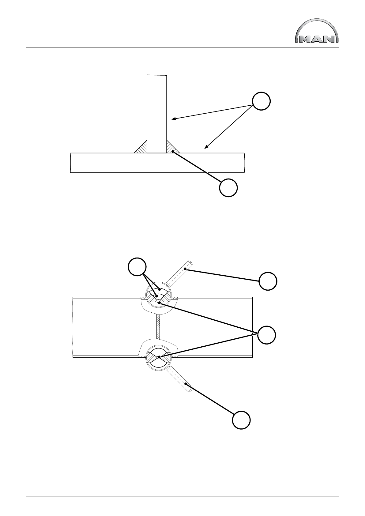
III. Chassis
Fig. 02-III: Undercuts
2
T_993_000022_0001_Z
1
1) Weld seam
2) Avoid undercuts at the locations shown
Fig. 03-III: Welding an X and Y seam
1
3
2
T_993_000023_0001_Z
3
1) Weld seam with two passes
2) Root pass
3) Welding electrode
MAN Guide to fitting bodies TGL/TGM Edition 2018 V2.0 33
Page 48

III. Chassis
Vertical welding shall be carried out from bottom to top (see Fig. 04-III).
Fig. 04-III: Vertical welding
2
3
T_993_000024_0001_Z
1
1) Welding electrode
2) Direction of welding
3) Proles to be welded
To prevent damage to electronic subassemblies (e.g. alternator, radio, FFR, EBS, EDC, ECAS) keep to the following
procedure:
• Disconnect the minus and plus cables of batteries, join the loose ends of the cables (- to +).
• Turn on the battery master switch (mechanical) or bypass the electric battery master switch on the solenoid
(disconnect cables and join).
• Attach the earth clip of the welding apparatus directly to the point to be welded, ensuring good conductivity
(see above).
• Connect the parts to be welded with each other (e.g. connect both parts to the earth clip).
Electronic sub-assemblies need not be disconnected if the above prerequisites are precisely met.
34 Edition 2018 V2.0 MAN Guide to fitting bodies TGL/TGM
Page 49

III. Chassis
1.3.3 Drill holes, riveted and bolted connections
Connections between frame parts and frame add-ons (e.g. corner plates with cross member, thrust plates, platform
corner pieces, tank brackets and so on) are realised by means of rivets or bolts during series production.
Drill holes in frame side member
The drill holes in the frame web are to be used for connections to the frame.
The hole pattern extends in parts along the entire length of the frame side member. If required, the exact hole pattern
can be accessed at www.manted.de under “Frame side member”. Drill-hole and edge distances are shown
in Fig. 05-III. If the existing drill holes do not enable the connection to be realised, it is possible to drill holes
in the web of the side member in accordance with Fig. 05-III. Drill holes can be made (in the fame web) along
the entire useful length of the frame. Drilling must not damage any of the parts located on the inner side (e.g. electric
wiring, compressed-air lines). All drill holes must be deburred after drilling and the drilling swarf removed.
In addition, it must be ensured that subsequently drilled holes are adequately protected against corrosion
(see Chapter III, Section 1.3.1).
Fig. 05-III: Distances between drill holes
b b
a ≥ 40 mm
b ≥ 50 mm
c ≥ 25 mm
d ≤ 14 mm on the TGL
d ≤ 16 mm on the TGM
d ≤ 16 mm on the TGS/TGX
Ød
b b
b b aa
c
T_993_000025_0001_Z
MAN Guide to fitting bodies TGL/TGM Edition 2018 V2.0 35
Page 50

III. Chassis
Important notice
Drill holes in the upper and lower ange
As a matter of principle, it is not permitted to subsequently drill any holes in the upper and lower anges of the
frame side member (Fig. 06-III).be selected; it must at minimum possess the same yield strength and tensile
strength as the material to be welded.
Fig. 06-III: Drill holes in the uooer and lower ange
T_993_000027_0001_Z
The only exception to drilling holes in the upper and lower ange is at the rear end of the frame behind the nal
cross member or the last cross member (in cases where no nal cross member has been tted). In addition, the use
of thrust plates in this area is necessary. Moreover, any holes in the upper and lower anges not used for bodywork
shall nevertheless be occupied by bolt connections of the frame and auxiliary frame (Fig. 07-III).
Fig. 07-III: Drill holes at frame end
1) Auxiliary frame
2) Direction of travel
3) Frame end (vehicle)
1
2
3
T_993_000028_0001_Z
36 Edition 2018 V2.0 MAN Guide to fitting bodies TGL/TGM
Page 51

III. Chassis
Bolted connections on chassis frame
If ex works bolted connections are changed, a bolted connection of equal quality as per manufacturer’s
specications must be restored in accordance with MAN standard M3059 (for obtaining this standard,
see www.ptd.man.eu). For this purpose, the following aspects of the bolted connections
must be identical:
1. Number and location of bolted connections (e.g. at connections of cross members)
2. Strength class (e.g. ribbed bolts 10.9, hexagonal ange nuts 10)
3. Types of nuts and bolts (ribbed bolts/hexagonal ange nuts)
4. Thread dimensions (e.g. M14 x 1.5)
Tightening torques are to be applied as per MAN standard M3059-1. To the end, the total coefcients of friction of
the nuts and bolts must be between µ
= 0.09 to 0.15.
tot
MAN recommends the use of ribbed bolts/hexagonal ange nuts as per MAN standards M7.012.04/M7.112.40.
If connections are disassembled, use new nuts and bolts on the tightening side when reassembling ribbed bolts.
The tightening side can be identied by slight grooves on the ribs in the bolt/nut ange (see Fig. 08-III).
Fig. 08-III: Marks on nips on the tightening side
T_993_000026_0001_Z
Alternatively, in accordance with manufacturer’s specications it is also possible to use high-strength rivets
(e.g. Huck-BOM, blind fasteners). A riveted joint must be at least equivalent to a bolted connection in terms
of design and strength.
MAN Guide to fitting bodies TGL/TGM Edition 2018 V2.0 37
Page 52

III. Chassis
1.4 Fire-protection measures for vehicle bodies and modifications
This chapter contains basic information as well as specic notes concerning re-protection measures for bodies
and modications on MAN chassis.
Fires can originate from:
• vehicle bodies or modications
• falling cargo (e.g. wood chips)
• the operational environment of the vehicle
• the surface temperature of exhaust silencers and exhaust pipes.
1.4.1 General
An increasing variety of transport tasks and vehicle applications results in a large number of causes of res in
vehicles and cargo. It is mandatory for the body manufacturer or converter to comply with the specications set
down in MAN‘s Guideline to tting bodies, Section I-Applicability and legal agreements -3.4 Operational and road
safety.
It is mandatory for the body manufacturer or converter to initiate the re-protection measures appropriate for
the type of application/operation during conversion of the vehicle.
In particular, information relevant to registration, country-specic regulations and laws must be observed.
The body manufacturer or converter must point out the corresponding re-protection measures in the operating
instructions for its body and refer the end user to the particularities thereof.
The following applies to all re-protection measures taken by body manufacturers and converters:
MAN can provide no information on the effectiveness of the measure used, responsibility lies with the company
performing the modication.
1.4.2 Statutory requirements
MAN delivers chassis that are already equipped ex works in accordance with national ADR regulations.
No component or system on the chassis with relevance to ADR/GGVS may be modied during work on
the body/conversion unless necessitated by the respective national regulations to be complied with.
It is mandatory for body manufacturers and converters to comply with ADR/GGVS regulations and country-specic
laws and regulations.
Please see www.manted.de for further information. Registration is required.
38 Edition 2018 V2.0 MAN Guide to fitting bodies TGL/TGM
Page 53

III. Chassis
1.4.3 Measures in the vicinity of the engine and exhaust system
In general, modications to the exhaust system are to be avoided. Various factory options are available for
MAN chassis and body builders must check to see if these can be used on a case-by-case basis.
Temperatures of 250 – 300°C occur on the surface of the exhaust system.
MAN recommends the installation of heat shields or heat-protection mats as required on parts of the vehicle/body
that exhibit high temperatures.
With regard to vehicles fullling the EURO 6 exhaust standard, it must be noted that the diesel particulate lter
(DPF) is subject to automatic regeneration cycles. The soot particles are collected and converted into CO2 in the
diesel particulate lter (DPF). This process is known as regeneration. A high exhaust gas temperature is required
upstream of the DPF for this purpose. Regeneration usually takes place automatically during driving operation and
is not noticed.
In this regard, please note the detailed information in the vehicle‘s operating instructions.
Warning notice
FIRE RISK!
Exhaust system becomes extremely hot and requires a long time to cool down.
Combustible materials, dust and vapours can be ignited especially easily, e.g.:
• If they are lying on or adhering to the exhaust system
• When refuelling, near fuel, coal, wood or grain storage facilities or similar
• On grass surfaces, hay, straw, foliage or other vegetated areas.
• When loading and unloading dangerous goods vehicles
Please see the further information in the vehicle operator‘s manual regarding this.
1.4.4 Measures on the air intake system
In order to avoid drawing in burning cigarette ends or similar, a so-called cigarette mesh must be tted directly over
the air intake in the same fashion as the mesh installed on production vehicles (non-ammable material, mesh size
SW6, area of the open cross-section at least that of the intake air scoop on the air lter).
Warning notice
There is a risk of vehicle re if this requirement is not observed!
MAN can provide no information on the effectiveness of the measure used, responsibility lies with the company
performing the modication.
MAN Guide to fitting bodies TGL/TGM Edition 2018 V2.0 39
Page 54

III. Chassis
1.4.5 Electric wiring/fittings
Overloading, external thermal inuences, sparks produced by improper connections or loose plug connectors in
the electric wiring can result in a vehicle re.
Electric wiring in the body, in particular wiring carrying heavy loads, must be adequately dimensioned and equipped
with fuses appropriate for the maximum current draw.
When connecting additional electrical consumers, the electrical interfaces of the vehicle described in
the Guideline to tting bodies are to be employed.
Electric wiring is to be routed in such a manner that it is protected by adequate distance from the thermal effects of
heat sources such as the engine, the exhaust system and son on (see Chapter III, Section 1.4.3 „Measures in
the vicinity of the engine and exhaust system“).
If this is not possible, the wiring must be protected by means of suitable insulation measures such as covers,
corrugated tubes/protective hoses, ducts and so on.
There must be no chang points on sharp edges, protruding threaded bolts, nuts, heads of screws and so on.
Connections between individual cables must be implemented professionally and correctly, using plug connectors.
The requisite spare parts can be obtained from the MAN Spare-parts Service.
Important notice
Subsequent connection to existing electric wiring by means of insulation displacement connectors or simply
twisting or soldering is forbidden. Soldered connections are not permitted in movable wiring.
Any electric wiring/cable harnesses on the chassis damaged during assembly of the body must be replaced.
More detailed information can be found in Chapter III- Chassis – 8.0 Electrical/electronic system (vehicle electrical
system).
40 Edition 2018 V2.0 MAN Guide to fitting bodies TGL/TGM
Page 55

III. Chassis
2.0 Overall vehicle
2.1 General
This chapter contains basic terms as well as specic notes concerning the modication of MAN vehicles.
In particular, information relevant to registration must be observed.
2.2 Terms, dimensions and weights
The terms, dimensions and weights below are to be observed when modifying vehicles and bodywork.
Information
National regulations take priority over technically permissible dimensions and weights if they restrict the technically
permissible dimensions and weights.
2.2.1 Theoretical wheelbase
The theoretical wheelbase is a variable that assists in determining the position of the centre of gravity and the axle
loads. It depends on the:
• Number of axles
• Arrangement of axles
• Distance between axles
• Permissible loads on individual axles
The theoretical wheelbase is the distance between the theoretical front-axle centerline and the theoretical rear-axle
centerline.
Theoretical axle centerlines are used as reference points in order to simplify calculations. The reference point is
needed in order to group several axles at one point. The permissible axle loads of the axles to be grouped may be
the same or different.
An example can be seen in Fig. 09-III, where both front axles are combined to a theoretical front-axle centerline and
both rear axles to a theoretical rear-axle centerline.
MAN Guide to fitting bodies TGL/TGM Edition 2018 V2.0 41
Page 56

III. Chassis
Fig. 09-III: Theoretical wheelbase and overhang on a four-axle vehicle with two front and two rear axles
(random axle-load distribution)
12
l
12
G
zul1
G
zul2
l
23
G
zul3
l
t
l
34
G
zul4
U
t
T_996_000012_0001_Z
1) theoretical rear-axle centerline
2) theoretical front-axle centerline
l
, l23, l34 distance between the respective axles
12
G
, G
, G
, G
zul1
zul2
zul3
permissible axle load of the respective axles
zul4
lt theoretical wheelbase
Ut theoretical overhang
Formulae for calculating the theoretical wheelbase in different axle congurations are described in
Chapter V Section 1.13.
42 Edition 2018 V2.0 MAN Guide to fitting bodies TGL/TGM
Page 57

III. Chassis
2.2.2 Theoretical and permitted overhang lengths
The theoretical overhang length is the distance between the theoretical rear-axle centerline and the end of
the vehicle, including its bodywork (see Fig. 10-III).
Fig. 10-III: Frame overhang on a three-axle vehicle with two rear axles and same rear-axle loads
1
2
T_996_000013_0002_Z
1) theoretical rear-axle centerline
2) theoretical overhang
The permitted overhang is an important dimension with regard to adhering to permissible axle loads and
the minimum front-axle load. As an example, Fig. 10-III shows the overhang on a three-axle chassis.
The permissible overhang for
• two-axle vehicles is 65%
• all other vehicles is 70%
of the theoretical overhang.
The theoretical overhang must not be longer than the permissible overhang.
However, the above-mentioned gures can be exceeded by 5% in the absence of equipment for pulling a trailer.
The prerequisite is that the minimum front-axle loads stated in Chapter III, Section 2.2.8, Table 01-III are maintained
in every operating state.
The terms “theoretical wheelbase” and “theoretical rear-axle centerline” are explained in Chapter III, Section 2.2.1.
In addition, the overhang length has a signicant effect on the distance that the rear end of the vehicle swings out
when the vehicle is driven in a circle. The national registration requirements must be complied with when planning
the body.
MAN Guide to fitting bodies TGL/TGM Edition 2018 V2.0 43
Page 58

III. Chassis
2.2.3 Permissible axle load
The permissible axle load is the total load on an axle or group of axles that may not be exceeded.
A distinction is made between
• technically permissible axle load
• nationally permissible axle load.
The technically permissible load on an axle or group of axles is restricted by the characteristics, condition and
design of the components of the axle(s), for example the axle itself, suspension, rims and tyres.
The nationally permissible load on an axle or group of axles depends on the laws and the criteria governing
the registration of vehicles in that specic country.
Important notice
Exceeding technically permissible axle loads is forbidden!
Under certain circumstances, nationally permissible axle loads may be exceeded. In this regard, the following must
be observed.
• A certicate of exemption must be obtained from the national authority responsible.
• A certicate of exemption can only be obtained in case where the nationally permissible axle loads are lower
than the technically permissible axle loads.
2.2.4 Permissible gross weight
The permissible gross weight is the total weight of a vehicle including its load that may not be exceeded.
A distinction is made between
• technically permissible gross weight
• nationally permissible gross weight.
The technically permissible gross weight is the weight that may not be exceeded, taking into account the
engineering design of the vehicle‘s components (e.g. axle concept, brake system, material stress).
The nationally permissible gross weight of a vehicle depends on the laws and the criteria governing the registration
of vehicles in that specic country.
Important notice
Exceeding the technically permissible gross weight is forbidden!
Under certain circumstances, the nationally permissible gross weight may be exceeded. In this regard, the following
must be observed.
• A certicate of exemption must be obtained from the national authority responsible.
• A certicate of exemption can only be obtained in case where the nationally permissible gross weight
is lower than the technically permissible gross weight.
44 Edition 2018 V2.0 MAN Guide to fitting bodies TGL/TGM
Page 59

III. Chassis
2.2.5 Permissible gross train weight
The permissible gross train weight is the weight of a train combination, i.e. tractor and trailer or semitrailer tractor
and semitrailer (including its load) that may not be exceeded.
A distinction is made between
• technically permissible gross train weight
• nationally permissible gross train weight.
The technically permissible gross train weight is the weight that may not be exceeded, taking into account the
engineering design of the vehicle’s components (e.g. axle concept, brake system, material stress).
The nationally permissible gross train weight depends on the laws and the criteria governing the registration of
vehicles in that specic country.
Important notice
Exceeding the technically permissible gross train weight is forbidden! Under certain circumstances, the nationally
permissible gross train weight may be exceeded.
In this regard, the following must be observed.
• A certicate of exemption must be obtained from the national authority responsible.
• A certicate of exemption can only be obtained in case where the nationally permissible gross train weight
is lower than the technically permissible gross train weight.
MAN Guide to fitting bodies TGL/TGM Edition 2018 V2.0 45
Page 60

III. Chassis
2.2.6 Axle overload
Axle overload is to be understood as the exceeding of both nationally permissible and technically permissible
axle loads.
Axle overloads can result from:
• loading the vehicle in front- or back-heavy manner
• overloading
• incorrect design of vehicle or body.
Important notice
Axle overloads must be avoided because otherwise, serious damage can occur to the vehicle and its components..
Fig. 11-III: Overload on front axle due to front-heavy loading
T_996_000014_0001_Z
46 Edition 2018 V2.0 MAN Guide to fitting bodies TGL/TGM
Page 61

III. Chassis
2.2.7 Wheel-load difference
The wheel-load difference describes the difference in load on the left and right wheel or set of wheels of an axle
or group of axles. The difference in load can cause a tilted position in relation to the road. In conjunction with a
laterally shifted center of gravity, this can lead to adverse driving characteristics. Furthermore, it can also result in
one-sided wear on the tyres.
Bodybuilders and operators must ensure that the wheel-load difference in all operating states (laden and unladen) is
as low as possible. An uneven load distribution as a result of the body can, for example, be countered by relocating
parts such as the tank, battery box and spare wheel.
If there are increased wheel-load differences, ESP (Electronic Stability Program) should be selected as alternative
equipment in order to improve driving stability.
The maximum wheel-load difference must not exceed 10% of the actual (1) axle load, but 5% of the permissible (2)
axle load. The smaller value is the decisive factor (see red line in Fig. 12-III).
In addition, the permissible load of the tyre and rim combination should be checked. Information concerning this
can be found in the technical manuals of the tyre and rim manufacturers.
Proceed as follows to determine the maximum permissible wheel-load difference per axle or group of axles.
Step 1: calculate the limit value of the axle load = ∙ permissible axle load
0,05
0,1
Step 2: determine the applicable range: Range A ≤ limit value
Range B > limit value
Step 3: calculate the permissible wheel-load difference
If the actual axle load is in Range A, the formula
- permissible wheel-load difference = 0.1 x actual axle load applies.
If the actual axle load is in Range B, the formula
- permissible wheel-load difference = 0.05 x permissible axle load applies.
Step 4: check the permissible wheel loads
Fig. 12-III: Representation of the permissible wheel-load difference (the numerical values apply to this
example; they are not universally applicable)
Wheel-load
difference [kg]
400
(1)
(2)
200
A B
4000
(3) (4)
8000
T_354_000001_0001_D
Actual axle
load [kg]
1) 10% of the actual axle load 2) 5% of the permissible axle load
3) Limit value between Ranges A and B 4) Permissible axle load
MAN Guide to fitting bodies TGL/TGM Edition 2018 V2.0 47
Page 62

III. Chassis
Example:
Axle data:
Actual weights:
• Unladen: 3000 kg; (with equal distribution 1500 kg per wheel)
• Laden: 7800 kg; (with equal distribution 3900 kg per wheel)
Permissible axle load: 8000 kg
Tyres: 315/80R22,5 with load index 156
Step 1: calculate the limit value of the axle load
Limit value =
Step 2: determine the applicable range
• Unladen: < limit value (3000 kg < 4000 kg) -> Range A
• Laden: > limit value (7800 kg > 4000 kg) -> Range B
Step 3: calculate the permissible wheel-load difference
• Unladen: 0,1 x 3000 kg = 300 kg (± 150 kg per wheel)
A load of 1350 kg is thus permitted on one side and 1650 kg on the other.
• Laden: 0,05 x 8 000 kg = 400 kg (± 200 kg per wheel)
A load of 4100 kg is thus permitted on one side and 3700 kg on the other.
Step 4: check the permissible wheel loads
Load index 156 means that the permissible tyre-load capacity is 4000 kg.
In this example, the tyre-load capacity thus limits the possible wheel-load difference to 200 kg when laden.
(± 100 kg per wheel)
5 (%)
⁄
(10 (%)
x 8000 kg = 4000 kg
48 Edition 2018 V2.0 MAN Guide to fitting bodies TGL/TGM
Page 63

III. Chassis
2.2.8 Minimum front-axle load
To ensure proper steering, the front axle of the vehicle, depending on model range and number of axles, must exhibit
a given minimum load as per Table 01-III in all load conditions of the vehicle
.
Fig. 13-III: Minimum load on front axle
T_996_000016_0001_Z
MAN Guide to fitting bodies TGL/TGM Edition 2018 V2.0 49
Page 64

III. Chassis
Notes on use of the table:
• If there is more than one front axle, the % value is the sum of the front axle loads.
• Three-axle vehicles with liftable leading or trailing axle must be considered as two-axle drive when axle
lift is actuated. In this condition, the higher minimum front axle load of two-axle drive vehicles applies. The
empty condition must be considered with both lifted and lowered axle.
Table 01-III: Minimum loading of front axle(s) of the TGL/TGM in every load situation expressed as
a percentage of the respective vehicle‘s actual weight
Minimum loading of front axle in every load situation expressed as a percentage of the respective vehicle‘s actual weight
GW = gross weight
RDT = rigid-drawbar trailer
CAT = center-axle trailer
without
RDT / CAT
Solo vehicle
with
RDT / CAT
Other tail load, e.g.
crane, liftgate
Series
Number of
axles
TGL Two axles 25% 30% 30%
Two axles 25% 30% 30%
TGM
More than two
axles
20% 25% 25%
With combined rear loads like rigid drawbar trailers with loading crane for example, the higher minimum front-axle
load applies.
The values apply including any additional tail loads such as
• nose weight through central axle trailer,
• loading crane on vehicle tail,
• Lift gates
• transportable fork-lift trucks.
50 Edition 2018 V2.0 MAN Guide to fitting bodies TGL/TGM
Page 65

III. Chassis
2.2.9 Calculating the axle load and weighing procedure
It is essential that an axle load calculation be completed in order to ensure correct design of the body.
The weights given in the sales documents only apply to production standard vehicles. Weight differences can
be caused by optional equipment or manufacturing tolerances. Manufacturing inaccuracies (within tolerances)
may occur.
Achieving optimum compatibility between bodywork and truck is only possible if the vehicle is weighed before any
work on the body is commenced. The weights thus obtained are then taken as a basis for an axle load calculation.
The vehicle must be weighed subject to following conditions:
• Without the driver
• With a fully lled AdBlue® tank and fully lled fuel tank
• With the handbrake released and the vehicle secured with chocks
• If tted with air suspension, raise the vehicle to normal driving position
• Liftable axle(s) must be raised to the normal driving position (as in loaded condition)
• Do not actuate any moving-off aid.
Observe the following sequence when weighing a vehicle (leading or trailing axle relates to the rear axle):
Two-axle vehicles:
• 1st axle
• 2nd axle
• whole vehicle as a check
Three-axle vehicles with two rear axles:
• 1st axle
• 2nd together with 3rd axle
• whole vehicle as a check
Four axle vehicle with two front and two rear axles:
• 1st together with 2nd axle
• 3rd together with 4th axle
• whole vehicle as a check
Four-axle vehicle with one front and three rear axles:
• 1st axle
• 2nd together with 3rd and 4th axles
• whole vehicle as a check.
2.2.10 Rolling circumference and difference in rolling circumference
The rolling circumference is the distance a tyre covers in the course of a single revolution without slip.
Different tyre sizes on the front and rear axle(s) can only be tted to all-wheel-drive vehicles (including HydroDrive)
if the difference in rolling circumference of the tyres used does not exceed 2%.
In the case of non-all-wheel-drive vehicles, the difference in rolling circumference may not exceed 10%.
The basis for calculation is always the circumference of the smaller tyre.
MAN Guide to fitting bodies TGL/TGM Edition 2018 V2.0 51
Page 66

III. Chassis
2.3 Modifications to the overall vehicle
In general, modications to the complete vehicle should only be made in exceptional cases. It is essential to
comply with all manufacturer’s specications and to agree any modications with MAN (for the address, see
“Publisher” above).
In this context, individual components cannot be regarded individually, because they are usually part of systems
and functions of the complete vehicle. The cross members of the chassis frame are an example of this. Together
with the frame side members, they form the support structure of the truck and affect many other functions. This
means they are subject to heavy loads and may not be modied.
2.3.1 Modifications to the wheelbase
Every change of wheelbase requires manufacturer’s conrmation. It is assumed that any change to the wheelbase
will only be carried out subsequent to receipt of the manufacturer’s approval.
Notes on applying for manufacturer’s conrmation can be found in Chapter I, Section 5.2.1. The conversion data le
associated with changes to the wheelbase and/or frame overhang will be provided together with the conrmation.
Technical design regulations applicable to steering (in particular 70/311 EEC, ECE-R79) mean that, depending upon
the number and type of steered axles, wheelbase, tyres axle loads and gross weight, chassis of MAN model ranges
are tted with different steering wheels (diameter), steering gear (range of ratios) and steering oil
piping (cooling coils).
As a basic principle, it must be ensured that the new wheelbase is within the model limit.
“Within the model limit” means that the new wheelbase is neither
- shorter than the shortest nor
- longer than the longest standard wheelbase for the same model of vehicle.
“The same model of vehicle” means vehicles with
- the same model number
- the same type of vehicle and
- the same wheel conguration
Important notice
Any shortening or extending of wheelbases exceeding this may only be carried out by MAN or its qualied
conversion suppliers (“qUL”) subsequent to consultation with MAN.
In addition, on TGL/TGM vehicles
®
• tted with electronic-hydraulic steering of the trailing axle “EHLA
the wheelbase. Modications to the steering system, however, are not permitted.
” it is possible to extend and shorten
52 Edition 2018 V2.0 MAN Guide to fitting bodies TGL/TGM
Page 67

III. Chassis
Type of wheelbase modication
Modications to the wheelbase can be carried out in one of the following two ways:
I. Relocating the entire rear-axle unit
II. Disconnecting the frame side members (inserting or removing a section of the frame).
In the case of the TGL/TGM, MAN recommends relocating the rear-axle unit, especially when the wheelbase is to
be changed to the next shortest or next longest standard wheelbase available. Due to the existing hole pattern in
the frame side member (distance between holes is 50 mm), this can most often be done without having to drill
additional holes or carry out welding.
Irrespective of the type of wheelbase modication, the following must be observed.
• The maximum distance between cross members subsequent to wheelbase modication may
not exceed 1200 mm. A tolerance of +100 mm is permissible.
• Modications to the propshaft train must be carried out according to these guidelines to tting bodies
(see Chapter III, Section 6.5 and the instructions provided by the propshaft manufacturer. If the new
wheelbase is the same as a standard wheelbase, then the arrangement of the propshaft and cross members
must be the same as that for a vehicle with standard wheelbase.
• Chapter III, Sections 6.3.5.2 and 8.2.1 apply with regards to the relocation of air and electrical lines. CAN
cables may not be cut. For this reason, longer routes must be selected when shortening wheelbases. More
over, rings and loops may not be formed when routing cables. During wheelbase extensions all rear-axle
related control units and sensors must be relocated with the axle, which is why adapter cable harnesses
are available for all the aforementioned equipment. System, method and item numbers are described in
detail in Chapter III, Section 8.2.
I. Relocating the entire rear-axle unit
If the rear-axle unit is relocated, the axle mounting, axle guide and cross members must be attached using rivets
or MAN double-nip countersunk bolts in accordance with Chapter III, Section 1.3.3 of the MAN guidelines to tting
bodies. The distance between drill holes specied there must be adhered to!
In the case of vehicles with dropped frames, the axle guide and suspension (e.g. spring hangers, longitudinal control
arm brackets) may not be located in the area in front of or within the bends in the frame. A minimum clearance of
100 mm to the second frame bend is assumed (see Fig. 14-III).
Fig. 14-III: Forbidden zone for rear axle guide
T_996_000017_0001_Z
MAN Guide to fitting bodies TGL/TGM Edition 2018 V2.0 53
Page 68

III. Chassis
II. Separating the frame side member
If the wheelbase modication is carried out by separating the frame side member, it is mandatory for welding to
comply with the specications in the MAN guidelines to tting bodies (see Chapter III, Section 1.3.2). The original
frame material must be used for any part inserted in the frame, e.g. frame side members, frame inserts. The material
specications can be found in Chapter III, Section 4.2. It is recommended that the frame side members are
pre-heated to 150°C – 200°C.
The frame must not be separated in the vicinity of:
• Axle guides and suspension (e.g. spring hangers, trailing arm mountings), minimum distance 100 mm
• Bends in the frame, minimum distance 100 mm
• Points where loads are introduced
• Gearbox mountings and cross members (also transfer cases on all-wheel-drive vehicles)
• Engine mounting
• Points where loads are introduced from bodywork
With the exception of Type N48, the frames of TGL/TGM vehicles have straight-through frames without bends.
On vehicles with straight frames behind the cab, the area in which weld seams for wheelbase modications are
permitted begins 100 mm behind the gearbox cross member and ends 100 mm ahead of the frontmost rear-axle
guide (see Fig. 16-III).
On vehicles with dropped frames behind the cab, the area in which weld seams for wheelbase modications
are permitted begins 100 mm behind the bend and ends 100 mm ahead of the frontmost rear-axle guide
(see Fig. 15-III).
Welded seams along the longitudinal axis of the vehicle are not permitted!
Fig. 15-III: Permissible area for welding dropped frames
T_993_000029_0001_Z
Fig. 16-III: Permissible area for welding straight frames
54 Edition 2018 V2.0 MAN Guide to fitting bodies TGL/TGM
T_994_000030_0001_Z
Page 69

III. Chassis
If the wheelbase modication is carried out by separating the frame side member, weld seams for shortened
wheelbases must be secured by means of inserts. Frame inserts must be in accordance with the following:
Fig. 17-III: Inserts for wheelbase shortening
2
=
=
1) Frame insert
2) Frame side member
Fig. 18-III: Inserts for wheelbase extension
≥550
≥50
=
≥50
≥25
=
T_993_000030_0001_Z
≥25
1
1) Frame insert
2) Frame side member
3) Prole section
2
≥ 300
≥ 50
≥ 25
≥ 50
≥ 375
T_993_000031_0001_Z
3
≥ 25
1
MAN Guide to fitting bodies TGL/TGM Edition 2018 V2.0 55
Page 70

III. Chassis
Location no. 1,Fig. 17-III and Fig. 18-III:
• Existing drill holes in the frame in the vicinity of the angle inserts are to be used. The following applies to
the arrangement of drill holes on the frame side member:
distance between holes ≥ 50 mm, edge distances ≥ 25 mm. The hole pattern can be found in
the corresponding frame side member drawing.
Location number 2, Fig. 17-III and Fig. 18-III:
• Where parts are in contact, the weld seam must be levelled (no. 2 in Fig. 17-III and Fig. 18-III).
Location no. 3, Fig. 17-III and Fig. 18-III:
• Where wheelbases are extended by means of inserting a frame side member prole, the material
specications as set down in the frame-section table and the maximum permissible wheelbases as per the
MAN guidelines to tting bodies must be observed. The frame track may not be changed. If the maximum
distances between frame cross members is exceeded, supplementary cross members must be inserted.
Moreover, the following notes on the dimensions of inserts must be observed.
Fig. 19-III: Inserts for wheelbase extension
A
b
a
h
A
T_993_000032_0001_Z
Key
• Height (h) ≥ Width (a)
• Width (a) is the same as the inner width of the frame (b), tolerance -5 mm.
• Thickness is the same as frame thickness, tolerance -1 mm. Material min. S355J2G3 (St.52-3)
• Rolled sections are not permitted.
On some long-wheelbase chassis, frame inserts are already tted between the front and rear axles at the factory.
Frame inserts may not be welded together with the frame side members. This can be avoided for example, by
inserting a copper-based separating foil which is removed once the welding work is completed.
Inserts used in changing the wheelbase may be simply butted-up to one another and may either be welded together
or joined with an overlapping plate (see Fig. 20-III, Fig. 21-III).
56 Edition 2018 V2.0 MAN Guide to fitting bodies TGL/TGM
Page 71

III. Chassis
Fig. 20-III: Insert covering, outside and inside
T_993_000033_0001_Z
The joint between the frame and the insert seam may not coincide with a weld seam in the frame - a distance
of 100 mm between seams must be observed.
This is easy to achieve if during cutting of the frame the location of the frame-insert joint is already taken into
account.
Fig. 21-III: Projecting inserts, outside and inside
T_993_000034_0001_Z
MAN Guide to fitting bodies TGL/TGM Edition 2018 V2.0 57
Page 72

III. Chassis
2.3.2 Modifying the frame overhang
“Frame overhang modication” refers to any changes in length from the middle of the last rear axle to the frame
end. As a basic principle it is possible to extend or shorten the overhang, provided the generally applicable national
conditions for registration are met.
Modications to the overhang can change the location of the center of gravity for payload and body as well as
the resulting axle loads. Prior to commencing work, an axle-load calculation must be carried in order to determine
whether the respective permissible axle load can be complied with (see Chapter V, Section 1.10 for an example of
an axle-load calculation).
Frame overhang extension
Frame extensions are only permissible using material identical to that used for the original frame (see Chapter III,
Section 4.2). Extensions must always be carried out on the frame end. Extensions consisting of several prole
sections are not permitted (cf. Fig. 22-III).
Fig. 22-III: Extension of frame overhang
1
T_995_000023_0001_G
1) Frame extension
The specications concerning welding on the frame (see MAN guidelines to tting bodies, Chapter III, Section 1.3.2)
must always be observed.
58 Edition 2018 V2.0 MAN Guide to fitting bodies TGL/TGM
Page 73

III. Chassis
Frame overhang extensions may not be carried out the area of the rear-axle mounting and guide or the axle
suspension (e.g. the air-spring-disc, leaf-spring-bearing and stabiliser mountings). The necessary minimum
distance of 100 mm must be maintained here. Cross members located in this area may not be relocated but must
be left where they are.
If the distance between any two cross members to the rear of the frame overhang extension is greater
than 1200 mm ± 100 mm, a supplementary cross member must be provided.
Fig. 23-III: Example of a leaf-sprung rear-axle unit with associated fastenings
1 2 3 4
T_994_000001_0001_Z
1) Center of rear axle
2) Axle mounting
3) Fastening of axle-suspension elements (leaf spring)
4) Frame side member
MAN Guide to fitting bodies TGL/TGM Edition 2018 V2.0 59
Page 74

III. Chassis
Fig. 24-III: Example of an air-sprung rear-axle unit with associated fastenings
1 2 3 4
T_994_000002_0001_Z
1) Center of rear axle
2) Axle mounting
3) Fastening of axle-suspension elements (air-spring-disc)
4) Frame side member
Important notice
On certain bodies it is sensible to use frame inserts in order to reinforce the modied overhang. For this reason,
MAN recommends using frame inserts.
The dimensions of the frame inserts depend on the following criteria:
• Type of load
• Introduction of force
• Body design
• Body type
• Dimension of auxiliary frame
Correspondingly prepared cable harnesses for frame extensions are available from MAN.
A detailed description of the procedure for extending cable harnesses, including a list of all permissible item
numbers can be found in Chapter III, Section 8.2. Notes on routing cable harnesses are to be observed.
For extending and re-routing compressed-air lines, refer to Chapter III, Section 6.3.5 of the guidelines to tting
bodies.
60 Edition 2018 V2.0 MAN Guide to fitting bodies TGL/TGM
Page 75

III. Chassis
Shortening the frame overhang
When a frame overhang is shortened, it is vital to adhere to the necessary minimum distance of 100 mm when
cutting the frame side member in the area of the rear-axle mounting and guide, as well as in the area of the axle
suspension (e.g. the air-spring-disc, leaf-spring and stabiliser mountings).
The cut must be so positioned that drill holes are not cut. If forces are introduced via drill holes at the frame end,
it is mandatory to adhere to the necessary distance to the extreme bre (Fig. 25-III Distance a).
Fig. 25-III: Distance to extreme bre of frame end
3
a
21
T_993_000035_0001_Z
a Distance to extreme bre
1) Frame side member
2) Frame overhang to be removed
3) Frame cut
Any cross members in the area of the cut must be relocated so that they can be bolted to the frame side member
again. The following applies:
Distance between cross members ≤ 1200 mm ± 100 mm
Where a frame overhang has been shortened, the cable harness installed as standard remains in use. In such cases,
Chapter III, Section 8.2 must be observed with regard to routing lines. Compressed-air lines may be shortened in
accordance with Chapter III, Section 6.3.5.
MAN Guide to fitting bodies TGL/TGM Edition 2018 V2.0 61
Page 76

III. Chassis
Important notice
MAN recommends reinforcing frames by means of frame inserts (see also frame overhang extension).
Use of nal cross member
Frame overhangs shortened or extended in accordance with the above specications (e.g. distance between cross
members, length of overhang) do not require a nal cross member when MAN underride protection is tted,
because this simultaneously functions as the nal cross member (not on Type N48).
A nal cross member is required:
• For operation with a trailer, also when ball-type couplings are in use (mounting of the socket)
• If a liftgate is tted (because MAN underride protection is not tted in this case)
• In the case of other rear loads or point loads (e.g. forklifts that are carried on the vehicle, loading
crane mounted on the frame end).
Fig. 26-III: Frame end without nal cross member
T_994_000003_0001_G
2.3.3 Modifying the wheel configuration
Modifying the wheel conguration means:
• tting of additional axles,
• removal of axles,
• Converting non-steered axles to steered axles
• Converting steered axles to non-steered axles
Important notice
Modifying the wheel conguration is forbidden. These conversions are carried out exclusively by MAN and its
qualied conversion suppliers (“qUL”). Manufacturer’s conrmation is necessary in every case.
62 Edition 2018 V2.0 MAN Guide to fitting bodies TGL/TGM
Page 77

III. Chassis
2.3.4 Changing the tyre type
Every change of tyre type requires manufacturer’s conrmation. Notes on applying for manufacturer’s conrmation
can be found in Chapter I, Section 5.2
The conversion data le associated with changes to the tyre type will, if required, be provided together with
the conrmation.
Technical limit values with regard to changing the tyre type can be found in Chapter I, Section 2.2.10
The notes in Chapter IV “Body” relating to anti-skid chains, clearance and the load ratings of tyres and rims
must be observed.
2.3.5 Changing the vehicle type and interchangeable operation as semitrailer
tractor/truck
Conversion of a truck into a semitrailer tractor or of a semitrailer tractor into a truck or using the same vehicle
alternatively as a semitrailer tractor or truck requires manufacturer’s conrmation from MAN.
Notes on applying for manufacturer’s conrmation can be found in Chapter I, Section 5.2 “Manufacturer’s
conrmation”.
Conversion of a semitrailer tractor to a truck or vice versa requires modication of the vehicle’s
parameterisation. The conversion data le associated with the chassis modication will be provided together
with the conrmation.
Depending on the selected vehicle (vehicle model), the change of vehicle type as well as interchangeable operation
may possibly require conversion measures to be taken in the area of the axle guide (e.g. springs, shock absorbers,
stabilisers) and the brakes.
The scope of such conversion measure depends on the selected vehicle model and the desired utilisation.
Therefore, in the case of new-build vehicles to be used as both semitrailer tractors and trucks, it must be determined
beforehand whether a truck chassis or a semitrailer tractor is to be used.
The conversion of a TGL or TGM chassis to a semitrailer tractor may only be carried out by MAN Truck & Bus AG or
its qualied conversion suppliers („qUL“).
MAN Guide to fitting bodies TGL/TGM Edition 2018 V2.0 63
Page 78

III. Chassis
2.3.6 Retrofitting additional units, attachments and accessories
If units, attachments or accessories are to be retrotted to the vehicle, they must be harmonised with MAN when
the measures are in the planning phase (for address see “Publisher” above).
Full and veriable documentation enabling a decision to be taken on the feasibility of the planned measures must
be submitted.
The background to this is that retrotting usually involves intervention in the control unit’s CAN. This also involves
additions to the programming of a vehicle’s software. Retrotted systems may under certain circumstances not be
assimilated into the vehicle’s own Trucknology® “Time maintenance system” or “Flexible maintenance system”.
For this reason, in the case of retrotted original parts, the same maintenance convenience will not necessarily result
as in a rst-time conguration.
Subsequent modication or expansion of the vehicle parameterisation can only be carried out with the help of
the MAN Service outlet responsible and MAN approval of the programs.
Warning notice
Under no circumstances does MAN accept design responsibility or responsibility for the consequences of
retrots that it has not approved. The stipulations stated in these guidelines and in approvals must be adhered to.
Approvals, reports and certication produced by third parties (e.g. test institutes) do not automatically mean the
issue of approval by MAN.
MAN may refuse approval even though third parties have issued appropriate clearance. Unless otherwise agreed,
approval only refers to the actual installation of the equipment. Approval does not mean that MAN has checked
the entire system with regard to strength, vehicle handling etc., and has accepted responsibility for warranty of
products. This responsibility is borne by the executing company. The retrotting of subassemblies and the like can
alter the technical data of a vehicle. The respective equipment manufacturer and/or the dealer/importer is
responsible for determining and issuing this new data.
64 Edition 2018 V2.0 MAN Guide to fitting bodies TGL/TGM
Page 79

III. Chassis
2.4 Homologated vehicle components / vehicle components relevant to safety
This section provides an overview of the most important homologated components of the vehicle and/or
components of the vehicle relevant to safety. They may not be changed without permission from MAN
(for address see “Publisher” above).
If any changes are made, the affected parts must be accepted again by a technical inspectorate.
The MAN warranty, however, is invalidated.
To be admissible for registration, vehicles must be congured in such a manner that they comply with the respective
country-specic laws. In order to ensure this in series production, parts relevant to registration are homologated.
Because of this, individual acceptances are no longer necessary.
Some of these components are listed below.
• Exhaust silencer
• Axles and running gear
• ADR components
• Trailer bracket and coupling
• Driveline and wheels
• Brake system
• Electrical components
• Cab
• Front cross member
• Camera system
• Fuel tank with mounting, hose and pump
• Steering system
• Lighting equipment
• Air intake
• Engine with engine attachments
• Register coupling
• Fifth-wheel coupling
• Final cross member for trailer coupling
• Underride protection, rear and side
• Adjuster mechanism
Further information concerning the homologation or relevance to safety of parts not listed above can be requested
from MAN (for address see “Publisher” above).
MAN Guide to fitting bodies TGL/TGM Edition 2018 V2.0 65
Page 80

III. Chassis
3.0 Cab
3.1 General
Modications to the cab’s structure (e.g. incisions/cut-outs, changes to the support structure including the seats
and seat fastenings, cab extensions, lowering of the roof) as well as modications to the cab mountings and tilting
mechanism are to be avoided wherever possible.
Warning notice
If modications to the cab are nevertheless necessary for technical reasons relevant to the body, they must be
harmonised with MAN during the planning phase (for address see “Publisher” above).
Modications to the cab may only be carried out by MAN or its qualied conversion suppliers (“qUL”).
The generally applicable national conditions for registration must be met in every case.
66 Edition 2018 V2.0 MAN Guide to fitting bodies TGL/TGM
Page 81

III. Chassis
3.2 Cabs
This section provides an overview of cabs including technical data for all the model ranges. The tabular overviews
provide information on designation, dimensions and a schematic representation for identication purposes.
TGL/TGM chassis are supplied with the following cab variants:
Table 02-III: TGL/TGM cabs
Designation Dimensions*
Name Technical designation
With D0836 (6-cyl.):
Left-hand drive vehicle: F99L10S
C
L
LX
DK
Right-hand drive vehicle: F99R10S
With D0834 (4-cyl.):
Left-hand drive vehicle: F99L12S
Right-hand drive vehicle: F99R12S
Left-hand drive vehicle: F99L32S
Right-hand drive vehicle: F99R32S
Left-hand drive vehicle: F99L37S
Right-hand drive vehicle: F99R37S
With D0834 (4-cyl.):
Left-hand drive vehicle: F99L58S
Right-hand drive vehicle:F99R58S
With D0836 (6-cyl.):
Left-hand drive vehicle: F99L57S
Right-hand drive vehicle: F99R57S
Length Width Height
(from Cab-0)
1.620 2.240 1.664
2.280 2.240 1.737
2.280 2.240 2.035
2.786 2.240 1.737
*) Cab dimensions without added on parts such as wings, skirts, mirrors, spoiler, etc.
MAN Guide to fitting bodies TGL/TGM Edition 2018 V2.0 67
Page 82

III. Chassis
3.3 Spoilers, roof extensions, roofwalk
The retrotting of a roof spoiler or aero package available ex works is possible. Genuine MAN spoilers and
aerodynamics kits for retrotting can be obtained from the Spare-parts Service. Drawings can be found in MANTED
under “Cabs”. Only the proper attachment points may be used when retrotting components to the cab roof.
Fastenings on cab roofs
Fig. 27-III: LX cab (L/R37)
Pos 3
Pos 4
Pos 16
Pos 17
Pos 7
Pos 8
Pos 9
Pos 10
Pos 13
Pos 12
Pos 11
T_629_000001_0001_G
Pos 18
Pos 19
Pos 14
Pos 15
Fig. 28-III: L cab (L/R32) Fig. 29-III: C cab (L/R 10-12)
Pos 26
Pos 20
Pos 21
Pos 23
Pos 22
Pos 25
Pos 24
T_629_000002_0001_G
Pos 20
Pos 21
Pos 22/24
Pos 23/25
T_629_000003_0001_G
Pos 26
68 Edition 2018 V2.0 MAN Guide to fitting bodies TGL/TGM
Page 83

III. Chassis
Table 03-III: Attachment points on cab roofs
Roof spoiler
with plastic high roof
Roof spoiler
with steel roof
Sunblind
with steel roof
Sun blind with plastic high roof
Air horn with plastic high roof
Rotating beacons with plastic high roof
Position Bolt / drill hole Tightening torque
3/3a
4/4a
M8 20 Nm
24/24a
25/25a
M8 20 Nm
26/26a
20/20a
21/21a
22/22a
M8 20 Nm
23/23a
7/7a
8/8a
9/9a
St 6,3 /
Ø 5,5 mm
10 Nm
10/10a
14/14a
15/15a
16/16a
17/17a
St 6,3 /
Ø 5,5 mm
10 Nm
18/18a
19/19a
11/11a
12/12a
13/13a
St 6,3 /
Ø 5,5 mm
10 Nm
• Drilling designation “a” is symmetric with y = 0
• Maximum load per bolt: 7.49 -12 t
• Maximum roof load: 30 kg
• Bolted connections over 3 offset points (not in one line)
• Center of gravity of roof extensions max. 200 mm above mounting level
• Drill holes in the plastic raised roof (laminated-in plates):
- Drilling axis parallel to the surface
- Drilling at an angle of ± 2 mm to the surface
- Drilling depth 10 mm + 2 mm
MAN Guide to fitting bodies TGL/TGM Edition 2018 V2.0 69
Page 84

III. Chassis
Information on additional attachment for roofwalk
Table 04-III: Additional attachment for roofwalk
Roofwalk on rear wall (all cabs)
Fig. 30-III: Additional fastener for roofwalk
Position Bolt / drill hole Tightening torque
1/1a
2/2a
M8 /
Ø 11,2 mm
20 Nm
2 1
• Drilling designation „a“ is symmetric with y = 0
• A support for the roofwalk must be tted to the rear wall
• All 4 attachment points 1/1a, 2/2a must be used
• The roofwalk must never be installed ahead of the rear edge of the roof hatch.
• Maximum weight of roofwalk: 30 kg
• Maximum load on roofwalk: 100 kg
T_629_000008_0002_G
70 Edition 2018 V2.0 MAN Guide to fitting bodies TGL/TGM
Page 85

III. Chassis
3.4 Roof sleeper cabs
Roof sleeper cabs (Topsleepers) can be tted when the following prerequisites are met:
• Emission level Euro 6 or lower (exception: roof sleeper cab not permitted for Euro 6 with C cab), see
Table 05-III
• If a roof sleeper cab is to be tted to the TGL model range (model code number N01 – N15) with C cab
(Compact) then it is necessary for the front mount bracket to be triple-bolted (production standard
since January 2008), see Fig. 31-III).
• Body approval must be obtained from MAN. This is the responsibility of the manufacturer of the roof sleeper
cab and not of the workshop tting it (see Chapter III, Section 2.3.6).
• The manufacturer of the roof sleeper cab is responsible for compliance with regulations (in particular safety
regulations, e.g. trade association guidelines), regulations and laws (e.g. GGVS/ADR).
• A suitable method of preventing the cab from closing by itself when it is tilted must be installed (e.g. by
tting a securing device).
• If the tilting process differs from that for the standard MAN cab, a simple but comprehensive operating
manual must be drawn up.
• The antennas tted on original MAN cab roofs must be properly relocated. This is intended to ensure good
quality reception and transmission of electromagnetic radiation in accordance with the EMC Directive.
Extension of the antenna cable is not permitted.
• When the cab has been tted, the dimensions stated for the resulting cab center of gravity must be adhered
to and veried (see Fig. 32-III)
• The maximum weights listed in Table 05-IIImust be adhered to.
Fig. 31-III: Double and triple bolting of mount bracket
T_417_000001_0001_G
Triple-bolting of the front mount bracket can be retrotted. Installation also requires the combination retaining
bracket and steering-gear mounting to be replaced. This modication must be carried out by a specialist workshop..
MAN Guide to fitting bodies TGL/TGM Edition 2018 V2.0 71
Page 86

III. Chassis
Fig. 32-III: Cab center of gravity with top sleeper
11
22
730 ± 10%
480
1) Topsleeper center of gravity
2) Resulting center of gravity
3) Cab center of gravity
4) Cab oor
820 ± 10%
560
33
44
T_629_000009_0001_G
72 Edition 2018 V2.0 MAN Guide to fitting bodies TGL/TGM
Page 87

III. Chassis
Table 05-III: Roof sleeper cabs, maximum weights and required modications to the cab mount
Max. additional
mass with
equipment
Series
Body permitted for
Cab
≤ Euro 5 Euro 6
Yes No C 110 kg L050-417050
TGL
Yes Ye s L 180 kg
Yes No C 110 kg
TGM
Yes Ye s L 180 kg
Modication of the cab mounts can be ordered from:
MAN Truck & Bus Deutschland GmbH
Truck Modication Center (TMC)
Otto-Hahn-Strasse 31
54516 Wittlich
E-Mail: trc@man.eu
Modication of cab mount
(ex works rear cab mount with air suspension) front
cab mount L050-417030
Front and rear cab mount modied
L050-417060
(ex works rear cab mount with air suspension) front
cab mount modied:
L050-417030
MAN Guide to fitting bodies TGL/TGM Edition 2018 V2.0 73
Page 88

III. Chassis
3.5 Fastening of warning plates to the front flap
To avoid damage to the front ap while fastening the warning plates, the procedure must comply with Service
Information (SI 288606). This is available from MAN workshops.
The location for fastening warning plates to the front cover is dened and released by MAN.
The following apply:
- The statutorily permitted vehicle width must not be exceeded.
- The supply of air to the radiator/engine must not be impaired.
- The connection must be adequately strong.
- Generally applicable guidelines concerning the transport of hazardous goods must be observed.
The description of the assembly procedure together with the necessary distances/clearances and the standard
parts to be used can be found in Service Information (SI 288606)
Fig. 33-III: Schematic representation of the dened position for warning plates
74 Edition 2018 V2.0 MAN Guide to fitting bodies TGL/TGM
T_639_000001_0001_G
Page 89

III. Chassis
4.0 Chassis frame
4.1 General
The frame forms the basis of the chassis. It accommodates the axles, the driveline with engine, gearbox and transfer
case and carries the cab and bodywork. Modications to the chassis frame must be carried out in accordance with
the specications set down in Chapter III, Section 2.3.
4.2 Frame materials
Modications to the frame side members and cross members of the chassis are permitted only when the original
frame material is used.
Table 06-III: Steel materials for MAN chassis frames
Material no.
Old material
designation
Old
standard
σ
0,2
N/mm
2
σ
B
N/mm
New material
2
designation
New standard
Prole
5, 33, 35,
1.0980 QStE420TM SEW 092 ≥ 420 480-620 S420MC DIN EN 10149-2
36, 37, 38,
39, 41, 42
1.0984 QStE500TM SEW 092 ≥ 500 550-700 S500MC DIN EN 10149-2
31, 32, 34,
40, 46
500 560-700 LNE500 NBR 6656:2008 43, 45
The assignment of model-range-specic frame proles (prole numbers), their material parameters and the
model-related allocation of frame proles can be found in Chapter III, Section 4.3.
nos.
MAN Guide to fitting bodies TGL/TGM Edition 2018 V2.0 75
Page 90

III. Chassis
4.3 Frame profiles
Precise data on the standard model-related allocation of frame side members are available via www.manted.de
(registration required).
The frame side member prole that is being used is described in up-to-date and binding form by:
• the chassis drawing
• the technical data sheet for the corresponding vehicle, see “Chassis” on www.manted.de.
The following tables show the series-specic prole data and type classication for the frame side members.
Fig. 34-III: Prole data of frame side members
Bo
t
h
y
e
ex
R
Bu
S
H
T_411_000001_0001_G
S Surface center of gravity
Table 07-III: Prole data for frame side members TGL/TGM
H h B
No
mm mm mm mm mm mm kg/m
5 220 208 70 70 6 10 16 420 480..620 2021 16 110 1332 121 121 85 53 16
35 220 212 70 70 4 10 11 420 480..620 1367 16 110 921 84 84 59 37 11
36 220 211 70 70 4,5 10 12 420 480..620 1532 16 110 1026 93 93 65 41 12
37 220 206 70 70 7 10 18 420 480..620 2341 17 110 1526 139 139 97 57 18
38 220 204 70 70 8 10 21 420 480..620 2656 17 110 1712 156 156 108 64 20
39 270 256 70 70 7 10 21 420 480..620 2691 15 135 2528 187 187 102 68 19
40 270 256 70 70 7 10 21 500 550..700 2691 15 135 2528 187 187 102 68 19
41 270 254 70 70 8 10 24 420 480..620 3056 15 135 2844 211 211 114 76 21
46 270 254 70 70 8 10 24 500 550..700 3056 15 135 2842 211 211 114 76 21
B
o
t R G σ
u
0,2
N/
mm
σ
B
N/mm2mm2mm mm cm4cm3cm3cm4cm3cm
2
A exe
y
IxW
W
x1
x2Iy
Wy1W
y2
3
76 Edition 2018 V2.0 MAN Guide to fitting bodies TGL/TGM
Page 91

III. Chassis
5.0 Frame attachments
5.1 General
Frame attachments are parts whose attachment points are located on the frame.
These include, for example:
• Fuel and AdBlue tank
• Side underride protection
• Underride protection
• Battery box
• Spare wheel
• Exhaust silencer
• Mudguard
Fig. 35-III: Example for frame attachments
T_996_000018_0001_G
MAN Guide to fitting bodies TGL/TGM Edition 2018 V2.0 77
Page 92

III. Chassis
5.2 Front underride protection
Motor vehicles used for the transport of goods that have at least four wheels and a maximum permissible mass of
over 3.5 t must be tted with front underride protection that is approved in accordance with Directive 2000/40/EC.
This shall not apply to:
• Offroad vehicles
• vehicles whose application is not compatible with the regulations for front underride protection.
The following criteria must be met in order to obtain registration as an off-road vehicle:
• At least 50% of the wheels are driven.
• A differential lock or ASR is tted.
• Gradeability of the individual vehicle ≥ 25%
• Plus at least four of the following requirements:
- Approach angle ≥ 25°
- Departure angle ≥ 25°
- Ramp angle ≥ 25°
- Ground clearance beneath the front axles is at least 250 mm.
- Ground clearance beneath the rear axles is at least 250 mm.
- Ground clearance between the axles is at least 300 mm.
Vehicles that do not meet the criteria for an off-road vehicle are tted with FUP that complies with the requirements
of Directive 2000/40/EC.
All-wheel-drive vehicles (wheel congurations e.g. 4x4, 6x4-4, 6x6, 8x6 and 8x8) and vehicles that meet the offroad criteria can be registered as off-road vehicles and are therefore not tted with front underride protection at the
factory.
If it is not possible to locate bodies or attachments (e.g. outriggers, tool boxes) such that the above stated criteria
are not violated then the vehicle must be retrotted with front underride protection, which is available from the MAN
spare parts organisation.
Responsibility for this lies with the body builder. MAN is not liable for any costs arising from the retrotting of front
underride protection to vehicles that were delivered as off-road vehicles.
All TGL 4x2, TGM 4x2, 6x2 and 6x4 vehicles are tted with FUP that complies with the requirements of Directive
2000/40/EC.
Exception
In the case of vehicles with a permissible gross mass of <= 7.5 t, only the ground clearance of <= 400 mm
(ground to lower edge of bumper) has to be complied with. The ground clearance is complied with as standard,
so that FUP is optional on vehicles of <= 7.5 t. If the load is increased to over 7.5 t, FUP has to be retrotted!
Important notice
Underride protection equipment may not be modied (e.g. by welding, drilling or modication of brackets). Non-
compliance voids type approval.
78 Edition 2018 V2.0 MAN Guide to fitting bodies TGL/TGM
Page 93

III. Chassis
5.3 Side underride protection
“Lateral protection device(s) (are) designed to offer effective protection to unprotected road users against the risk
of falling under the sides of the vehicle and atng caught under the wheels” (excerpt from ECE-R73). Trucks, tractor
units and their trailers with a permissible gross weight of > 3.5 t must be tted with side underride protection.
Exceptions applicable to the truck sector are as follows:
• Semitrailer tractor units (not semitrailers)
• Vehicles built for special purposes that are incompatible with the tting of side underride protection.
The following apply in Germany:
• The respective national approval authority can be applied to for certicates of exemption to cover
transfer trips of chassis.
• In this connection, “special vehicles” mainly means vehicles with side tipper. This only applies to vehicles
with side tippers and a body inside length of less than 7,500 mm. Neither vehicles for combined transport
nor off-road vehicles are exempt from the mandatory requirement for tting side underride protection.
MAN Guide to fitting bodies TGL/TGM Edition 2018 V2.0 79
Page 94

a al
≤ 300
≤ 550
III. Chassis
The corresponding national regulations must be observed when determining whether or not side underride
protection has to be tted.
Side underride protection for chassis can be delivered ex-works. Body builders who retrot side underride
protection can procure MAN proles, prole supports and components for assembly from the Spare-parts Service.
Important notice
The company installing or modifying side underride protection is responsible for compliance with national
regulations (regulated by Directive ECE-R73 01, in Germany by §32c StVZO (Road Trafc Licensing Regulations)).
It is not permissible to attach brake, air or hydraulic pipes to side underride protection. There may be no sharp
edges or burrs; the rounding-off radius for all parts cut to size by the body builder must be at least 2.5 mm; Rounded
bolts and rivets may project by a maximum of 10 mm. If the vehicle is tted with different tyres or different springs,
the height of the SUP must be checked and, if necessary, corrected. If there are several components in a row
(battery box, tool box) that serve as a form of SUP, a maximum distance of 25 mm is permissible but the rear
component may not project laterally outwards above the front one.
If it is necessary for the body builder to modify MAN’s original prole support for the SUP, then the relationship
between the span “I” and projection “a” shall apply as illustrated in the following diagram (Fig. 37-III). If, according
to expert opinion, the permitted dimensions are exceeded then the body builder must arrange for strength testing to
be carried out. The illustrations are only intended to clarify the dimensions for which the MAN side underride
protection meets strength requirements.
Note:
There is no side underride protection ex works for the N16, N26 and N48 models. In these cases, the body builder
must t side underride protection in accordance with the above-mentioned regulations.
Fig. 36-III: Side underride protection on the TGL/TGM
≤ 350
T_429_000001_0002_G
80 Edition 2018 V2.0 MAN Guide to fitting bodies TGL/TGM
Page 95

III. Chassis
Fig. 37-III: Graph for ascertaining span and projection for the TGL/TGM
Prol B
one rail
Prol A
one rail
900
Prol B
2 rails at the rest of the rail
800
700
Projection a
600
500
Überkrag
Stützenabstand
Span l
Prol B
2 rails at the rearmost
250 mm
500 1000 1500 2000 2500 3000
400
T_429_000003_0001_D
300
MAN Guide to fitting bodies TGL/TGM Edition 2018 V2.0 81
Page 96

III. Chassis
The following list shows which prole type (design) is used for which vehicles ex works.
For vehicles of model range TGL
• in exhaust-emission class Euro 5 and lower: Version B, one side guard
• in exhaust-emission class Euro 6: Version A
For vehicles of model range TGM
• in exhaust-emission class Euro 6 or lower and rim size > 19.5“: Version B, two side guards
• in exhaust-emission class Euro 5 or lower and rim size ≤ 19.5“: Version B, one side guard
• in exhaust-emission class Euro 6 and rim size ≤ 19.5“: Version A
The proles are shown below.
Fig. 38-III: Version A Fig. 39-III: Version B
25
20
100
200
9
100
30
T_429_000005_0001_G
82 Edition 2018 V2.0 MAN Guide to fitting bodies TGL/TGM
Page 97

III. Chassis
5.4 Rear underride protection
Chassis of the TGL and TGM model ranges are delivered ex works with different variants of MAN’s rear underride
protection. The respective variant is tted by MAN depending upon the vehicle‘s application (see Table 08-III).
MAN’s underride protection on the TGL/TGM is designed such that it also performs the function of the nal cross
member on vehicles not tted with a trailer coupling (see also Fig. 40-III). Optionally, rear underride protection can
be omitted and the chassis would in such cases be tted with a nal cross member with or without a hole pattern
for a trailer coupling (depending upon equipment tted).
In this case, the bodybuilder is responsible for tting a suitable rear underride protection approved in accordance
with the regulations. For retrotted rear underride guards, e.g. following shortening of the frame, the bodybuilder/
converter must ensure and verify that the regulations have been adhered to because the dimensions are dependent
upon the superstructure and can only be determined once the vehicle including the superstructure has been fully
completed. MAN underride protection devices are type-approved in accordance with Directive 70/221/EEC as last
amended by 2006/20/EU.
When a bodybuilder/converter ts an MAN underride protection device, it must be ensured that only MAN Verbus-Ripp bolts with shaft are used for making the bolted connection between the bracket and the frame and that
these are tightened on the nut side to a torque in accordance with MAN Standard M3059
(140 Nm for M12x1.5 threads).
Table 08-III: Underride protection variants and positions see Fig. 40-III)
Fitting item no. Type Use Y X*
81.41660-8170 TGL 384 mm 550 mm
81.41660-8186 TGL with trailer bracket when a ball-type coupling is tted 386 mm 550 mm
81.41660-8189 TGM N16 19.5" wheels 379 mm 550 mm
81.41660-8191 TGM N26 19.5" wheels 370 mm 550 mm
81.41660-8192 TGM 4x4 13 t BL N34, N36 376 mm 550 mm
81.41660-8195 TGM
81.41660-8204 TGM 4x2 and 6x2-4 22.5" wheels 359 mm 550 mm
81.41660-8205 TGM 4x2 22.5" wheels crane tipper 364 mm 550 mm
81.41660-8206 TGM 4x4 18-t crane tipper all-wheel drive 346 mm 550 mm
81.41660-8207 TGM 4x4 18 t/13 t BB 346 mm 550 mm
* maximum permissible distance as per Directive 70/221/EEC
4x4 13 t BL N34, N36 only with single tyres in sizes from
295/80R22.5" to 305/70R22.5"
376 mm 550 mm
MAN Guide to fitting bodies TGL/TGM Edition 2018 V2.0 83
Page 98

III. Chassis
Fig. 40-III: Dimensional specications for underride protection
y
x
T_429_000006_0001_G
The following dimensions must be observed.
x = vertical distance from lower edge of underride protection to the road surface for an unladen vehicle
y = horizontal distance from rear edge of underride protection to rear edge of body
Type-approved underride protection devices must never be modied (e.g. by making changes to weld seams,
drill holes, brackets) because this will invalidate certication/type approval!
84 Edition 2018 V2.0 MAN Guide to fitting bodies TGL/TGM
Page 99

III. Chassis
5.5 Fuel tanks
As far as space permits, fuel tanks can be moved and auxiliary ones installed. With large volumes, ensure an equal
distribution of load on the wheels, as far as possible (see Chapter III-Chassis Section 2.2.7 Wheel load difference).
If the tank shape has changed, the tank pick-up must be replaced and in certain cases the vehicle must be
parameterised again by a MAN service outlet.
The following overview applies:
OLD Tank prole NEW Tank prole
Exchange tank
pick-up necessary?
Yes Yes change of cross section
Yes Yes change of cross section
Yes No tank lling height
Yes No tank lling height
Yes No tank lling height
Parametrisation
necessary
Note
Yes No tank lling height
No No none tank lling height
MAN Guide to fitting bodies TGL/TGM Edition 2018 V2.0 85
Page 100

III. Chassis
For special fuel tank shapes, contact the manufacturer of the fuel tank.
If larger or auxiliary fuel tanks are tted after delivery from the factory, then the additional tank volume will be subject
to a mineral oil/fuel/energy tax by the territory into which it is being imported.
This regulation applies to modications carried out before the vehicle was registered in the customer’s name
(e.g. at the body builder) and to retrots carried out once the vehicle has already been registered in the end
customer’s name. Customers must be informed of this issue.
Fuel can only be carried tax-free in “main tanks” (and in reserve tanks up to a total volume of 20 litres). Main tanks
are the fuel tanks with which the vehicle was delivered, not those which were tted afterwards by a body builder or
workshop, for example.
According to the ADR directive, the maximum permissible total volume may not exceed 1500 l.
Country-specic ADR directives must be observed.
Country-specic guidelines must be observed in the event of modications.
The description of the procedure for the rst fuelling of twin or multi-tank systems can be found in the applicable
vehicle operating instructions or service information (SI 545200).
Information on use in mining:
Corrosion damage can occur on vehicles with aluminium fuel tanks which are used in coal mining or for coal transport.
Here, contact corrosion occurs between the elements aluminium and carbon.
MAN recommends selecting steel tanks when conguring vehicles for coal mining applications.
If no steel tanks are available in the desired size, then the tank system must be checked regularly.
Another option is to have the fuel tank professionally painted; regular checks are still recommended, however.
86 Edition 2018 V2.0 MAN Guide to fitting bodies TGL/TGM
 Loading...