

Man D2868 LE433, D2862 LE453, D2862 LE433, D2862 LE423, D2862 LE463 Operating Instructions Manual
...Page 1

Operating Instructions
MAN Marine Diesel Engines
D2868 LE433
D2862 LE433/453
D2862 LE423/443/463
51.99493-8578 “Translation of the original operating instructions”
Page 2

Information and Copyright
Subject to technical alterations in the interests of further development.
Reprinting, copying or translating of these instructions, even in part, is forbidden without written permission
from MAN. All legal copyrights remain the exclusive property of MAN.
© 2011
MAN Truck & Bus AG
Vogelweiherstraße 33
90441 Nürnberg
Germany
Tel.: +49 911 / 420-1745
Fax: +49 911 / 420-1930
E-Mail: engines.components@de.man-mn.com
Internet: www.man-engines.com
Editorial: EMDGG, Technical status: 07.2010
51.99493-8578
2
Page 3

Contents
Information and Copyright 2.................................................................
Contents 3................................................................................
Preface 4.................................................................................
Instructions 5..............................................................................
Declaration 6..............................................................................
Nameplates 7.............................................................................
Safety regulations 8........................................................................
Commissioning and operation 14..............................................................
Engine views V8-1200 (D2868 LE433) 14...................................................
Engine views V12-1800 (D2862 LE433) / V12-1650 (D2862 LE453) 16..........................
Engine views V12-1550 (D2862 LE423) / V12-1400 (D2862 LE443) / D2862 LE463) 18............
First commissioning 20....................................................................
Commissioning 22........................................................................
Starting 23..............................................................................
Operation monitoring system 24............................................................
Shutting down 98.........................................................................
Page
Maintenance and care 99....................................................................
Lubrication system 99.....................................................................
Fuel system 104..........................................................................
Cooling system 108........................................................................
Alternator 115.............................................................................
Temporary decommissioning of engines 115..................................................
Technical data 116...........................................................................
Troubleshooting table 128.....................................................................
Index 130...................................................................................
3
Page 4

Preface
Dear Customer,
these Operating Instructions are intended to familiarize you with your new MAN Diesel engine and how it
operates.
This manual is supplemented by the publication “Fuels, Lubricants and Coolants for MAN Diesel Engines"
and the “Service record book".
Note:
All three publications belong to the engine and must always be kept ready to hand near the en
gine in the engine room.
Comply in full with instructions relating to operation, prevention of accidents and environmental
protection.
MAN Diesel engines are developed and manufactured in line with the latest state of the art. However,
trouble-free operation and high performance can only be achieved if the specified maintenance intervals
are observed and only approved fuels, lubricants and coolants are used.
Note:
Only use fuels, lubricants etc. in accordance with MAN's regulations.
Otherwise the manufacturer's liability for defects will not apply!
For basic information on the fuels see the publication “Fuels, Lubricants and Coolants for MAN
Diesel Engines".
You can find the approved products in the internet under:
https://mmrepro.mn.man.de/bstwebapp/BSTServlet
It is imperative and in your own interest to entrust your MAN Local Service Centre with the removal of any
disturbances and with the performance of checking, setting, and repair work.
Yours faithfully,
MAN Truck & Bus AG
Werk Nürnberg
4
Page 5

Instructions
Important instructions which concern technical safety and protection of persons are emphasised as shown
below.
Danger:
This refers to working and operating procedures which must be complied with in order to rule out
the risk to persons.
Caution:
This refers to working and operating procedures which must be complied with in order to prevent
damage to or destruction of material.
Note:
Explanations useful for understanding the working or operating procedure to be performed.
5
Page 6

Declaration
6
Page 7

Nameplates
In all your correspondence please always quote en
gine model, serial number and job number (Order
number).
For this reason it is advisable to read off the data
from the engine type plates before putting the engine
into operation and to enter them in the appropriate
spaces.
The engine type plates are on the crankcase (see
illustration).
MAN Nutzfahrzeuge Aktiengesellschaft
Type
Engine No. / Engine No.
NI/II
Model
......................................................................
delivered on
......................................................................
installed on
......................................................................
Engine serial number
......................................................................
Order number
......................................................................
Temp. C
°
MAN Nutzfahrzeuge AktiengesellscMAN Nutzfahrzeuge Aktiengesellschaft
Nürnberg Works, Germany
Job No Rating kW
Power kWWorks No.
:
Engine No.TypeYear of manufacture.
Eng. speed 1/min
Operating altitude m uNNPower. PS
:
Speed rpm
:
Altitude mRating BHP
7
Serial NoModelYear
−0219
Page 8

Safety regulations
General notes
Handling diesel engines and the necessary resources is no problem when the personnel commis
sioned with operation and maintenance are trained accordingly and use their common sense.
This summary is a compilation of the most important regulations. These are broken down into main sec
tions which contain the information necessary for preventing injury to persons, damage to property and pol
lution. In addition to these regulations those dictated by the type of engine and its site are to be observed
also.
Important:
If, despite all precautions, an accident occurs, in particular through contact with caustic acids, fuel penetrat
ing the skin, scalding from hot oil, anti‐freeze being splashed in the eyes etc., consult a doctor immedi
ately.
1. Regulations designed to prevent accidents with injury to persons
During commissioning, starting and operation
D Before putting the engine into operation for the first time, read the operating instructions
carefully and familiarize yourself with the “critical" points. If you are unsure, ask your
MAN representative.
D For reasons of safety we recommend you attach a notice to the door of the engine
room prohibiting the access of unauthorized persons and that you draw the attention of
the operating personal to the fact that they are responsible for the safety of persons
who enter the engine room.
D The engine must be started and operated only by authorized personnel.
Ensure that the engine cannot be started by unauthorized persons.
D When the engine is running, do not get too close to the rotating parts. Wear close‐fitting
clothing.
D Do not touch the engine with bare hands when it is warm from operation - risk of burns.
D Exhaust gases are toxic. Comply with the instructions for the installation of MAN Diesel
engines which are to be operated in enclosed spaces. Ensure that there is adequate
ventilation and air extraction.
D For safety reasons a separate, functioning red emergency‐stop‐button for each
engine must be installed at every bridge (the engine must stop immediately when
the button is pressed once).
8
Page 9

Safety regulations
ËË
ËË
D Electrical accessories and equipment from other manufactures may only be
connected without the approval of MAN to the connections provided for the cu
stomer or shipyard.
The control of the engine may be adversely affected and thus may lead to property
damage or personal injury and is therefore not permitted.
MAN assumes no liability for any property damage or personal injury.
Connections to the following MAN components are prohibited:
- EDC engine control unit (K-Line, CAN-Bus)
- MAN internal or external throttle lever control system (CAN-Bus)
- Emergency steering control (serial, CAN-Bus)
- Display systems for alarms (serial, CAN-Bus)
Approved connectors on terminal box: X4, X8 and X9.
D Keep vicinity of engine, ladders and stairways free of oil and grease.
Accidents caused by slipping can have serious consequences.
During maintenance and care
D Always carry out maintenance work when the engine is switched off.
If the engine has to be maintained while it is running, e.g. changing the elements of
change‐over filters, remember that there is a risk of scalding. Do not get too close to ro
tating parts.
D Change the oil when the engines is warm from operation.
Caution:
There is a risk of burns and scalding. Do not touch oil drain plugs or oil filters with bare
hands.
D Take into account the amount of oil in the sump. Use a vessel of sufficient size to en
sure that the oil will not overflow.
D Open the coolant circuit only when the engine has cooled down.
If opening while the engine is still warm is unavoidable, comply with the instructions in
the chapter entitled “Maintenance and Care".
D Neither tighten up nor open pipes and hoses (lube oil circuit, coolant circuit and any ad
ditional hydraulic oil circuit) during the operation.
The fluids which flow out can cause injury.
D Fuel is inflammable. Do not smoke or use naked lights in its vicinity. The tank must be
filled only when the engine is switched off.
D When using compressed air, e.g. for cleaning the radiator, wear goggles.
D Keep service products (anti‐freeze) only in containers which can not be confused with
drinks containers.
9
Page 10

Safety regulations
D Comply with the manufacturer's instructions when handling batteries.
Caution:
Accumulator acid is toxic and caustic. Battery gases are explosive.
2. Regulations designed to prevent damage to engine and premature wear
Do not demand more from the engine than it is able to supply in its intended application. Detailed informa
tion on this can be found in the sales literature.
If faults occur, find the cause immediately and have it eliminated in order to prevent more serious damage.
Use only genuine MAN spare parts. MAN will accept no responsibility for damage resulting from the install
ation of other parts which are supposedly “just as good".
In addition to the above, note the following points:
D Never let the engine run when dry, i.e. without lube oil or coolant.
D When starting do not use any additional starting aids (e.g. injection with starting pilot).
D Use only MAN‐approved service products (fuel, engine oil, anti‐freeze and anti‐corrosion agent). Pay at
tention to cleanliness. The Diesel fuel must be free of water. See “Maintenance and care".
D Have the engine maintained at the specified intervals.
D Today modern components of diesel injection consist of high‐precision parts which are exposed to ex
treme stresses. The high‐precision technology requires the utmost cleanliness during all work on the
fuel system.
Even a particle of dirt over 0,2 mm can lead to the failure of components.
D Do not switch off the engine immediately when it is warm, but let it run without load for about 5 minutes
so that temperature equalization can take place.
D Never put cold coolant into an overheated engine. See “Maintenance and care".
D Do not add so much engine oil that the oil level rises above the max. marking on the dipstick.
Do not exceed the maximum permissible tilt of the engine.
Serious damage to the engine may result if these instructions are not adhered to.
D Always ensure that the testing and monitoring equipment (for battery charge, oil pressure, coolant tem
perature) function satisfactorily.
D It is advisable to switch off the engine if an alarm of any kind is displayed in the engine monitoring and
diagnostic system. If this is not possible for any reason, the engine should be run no faster than 1200
rpm until the fault is remedied, see page 24.
D Comply with instructions for operation of the alternator. See “Maintenance and care".
D Do not let the seawater pump run dry. If there is a risk of frost, drain the pump when the engine is
switched off.
10
Page 11

Safety regulations
3. Regulations designed to prevent pollution
Engine oil and filter elements / cartridges, fuel / fuel filter
D Take old oil only to an old oil collection point.
D Take strict precautions to ensure that no oil or Diesel fuel gets into the drains or the ground.
Caution:
The drinking water supply could be contaminated.
D Filter elements are classed as dangerous waste and must be treated as such.
Coolant
D Treat undiluted anti‐corrosion agent and / or anti‐freeze as dangerous waste.
D When disposing of spent coolant comply with the regulations of the relevant local authorities.
4. Notes on safety in handling used engine oil ∗
Prolonged or repeated contact between the skin and any kind of engine oil decreases the skin. Drying, irrit
ation or inflammation of the skin may therefore occur. Used engine oil also contains dangerous substances
which have caused skin cancer in animal experiments. If the basic rules of hygiene and health and safety
at work are observed, health risks are not to the expected as a result of handling used engine oil.
Health precautions:
D Avoid prolonged or repeated skin contact with used engine oil.
D Protect your skin by means of suitable agents (creams etc.) or wear protective gloves.
D Clean skin which has been in contact with engine oil.
- Wash thoroughly with soap and water. A nailbrush is an effective aid.
- Certain products make it easier to clean your hands.
- Do not use petrol, Diesel fuel, gas oil, thinners or solvents as washing agents.
D After washing apply a fatty skin cream to the skin.
D Change oil‐soaked clothing and shoes.
D Do not put oily rags into your pockets.
Ensure that used engine oil is disposed of properly
- Engine oil can endanger the water supply -
For this reason do not let engine oil get into the ground, waterways, the drains or the sewers. Violations are
punishable.
Collect and dispose of used engine oil carefully. For information on collection points please contact the
seller, the supplier or the local authorities.
∗ Adapted from “Notes on handling used engine oil".
11
Page 12

Safety regulations
5. Special instructions when working on the common rail system
Accident protection
D Risk of injury!
Fuel jets can cut through skin.
The atomisation of fuel creates a fire risk.
- When the engine is running never loosen the screw connections on the fuel's
high‐pressure side of the common rail system (injection line from the high‐pressure
pump to the rail, on the rail and on the cylinder head to the injector)
- Keep away from the engine when it is running
D Risk of injury!
When the engine is running the lines are constantly under a fuel pressure of up
to 1600 bar.
- Wait at least a minute until the pressure in the rail has dropped before loosening a
screw connection
- If necessary check the pressure drop in the rail with MAN‐Cats
D Risk of injury!
- People with pacemaker must keep at least 20 cm away from the running engine.
- Do not touch live parts on the electric connection of the injectors when the engine is
running.
Cleanliness
Today modern components of diesel injection consist of high‐precision parts which are exposed to extreme
stresses. The high‐precision technology requires the utmost cleanliness during all work on the fuel sys
tem.
Even a particle of dirt over 0,2 mm can lead to the failure of components.
The measures described as follows are therefore essential before work begins:
Risk of damage from penetration of dirt!
D Before working on the clean side of the fuel system clean the engine and the engine
compartment. During cleaning the fuel system must be closed.
D Carry out visual inspection for any leakage or damage to the fuel system
D Do not spray the high‐pressure cleaner direct onto the electric components, or alternati
vely keep them covered
D Do not carry out any welding or sanding work in the engine compartment during mainte
nance / repair
12
Page 13

Safety regulations
D Avoid air movements (any swirling of dust when starting engines)
D The area of the still closed fuel system must be cleaned and dried with the aid of com
pressed air
D Remove detached particles of dirt such as paint chippings and insulation material with a
suitable extractor (industrial type vacuum cleaner)
D Cover areas of the engine compartment from which dust particles could be detached
with clean foil
D Wash your hands and put on clean work clothes before starting the disassembly work
When carrying out the work it is essential to comply with the following measures:
Risk of damage from penetration of dirt!
D When the clean side of the fuel system has been opened it is not permissible to use
compressed air for cleaning
D During assembly work loose dirt must be removed with the aid of suitable extractors (in
dustrial type vacuum cleaners)
D Use only fluff‐free cleaning cloths on the fuel system
D Clean tools and working materials before starting to work
D Only tools without any damage may be used (cracked chrome coatings)
D When removing and installing components do not use materials such as cloths, cardbo
ard or wood since these could shed particles and fine fibres
D If any paint chips/flakes off when connections are loosened (from possible over‐coating)
these chippings must be carefully removed before finally loosening the screw connec
tion
D The connection openings of all parts removed from the clean side of the fuel system
must be immediately closed up with suitable caps/stoppers
D These caps/stoppers must be packed protected from dust prior to use and after being
used once they must be disposed of
D Following this all the components must be carefully stored in a clean, closed container
D Never use used cleaning or testing liquids for these components
D New parts must not be removed from their original packing material until directly before
use
D Work on removed components may be carried out only at a workplace specially equip
ped for it
D If removed parts are shipped always use the original packing material of the new part
13
Page 14

Commissioning and operation
Engine views V8-1200 (D2868 LE433)
2
3
4
10
5
6
7
1
9
8
3
8
11
12
10
14
Page 15

(1) Poly-V-belt guard
(2) Air filter
(3) Coolant filler neck
(4) Main fuse for voltage supply
(5) Oil drain valve engine
(6) Oil drain valve gearbox
(7) Oil filler neck
Commissioning and operation
(8) Oil filter
(9) Oil dipstick
(10) Fuel filter
(11) Sea water pump
(12) Engine terminal box EDC
15
Page 16

Commissioning and operation
Engine views V12-1800 (D2862 LE433) / V12-1650 (D2862 LE453)
2
3
4
5
6
1
9
8
7
3
8
10
11
12
10
16
Page 17

(1) Poly-V-belt guard
(2) Air filter
(3) Coolant filler neck
(4) Main fuse
(5) Oil drain valve gearbox
(6) Oil drain valve engine
(7) Oil filler neck
Commissioning and operation
(8) Oil filter
(9) Oil dipstick
(10) Fuel filter
(11) Sea water pump
(12) IEngine terminal box EDC
17
Page 18

Commissioning and operation
Engine views V12-1550 (D2862 LE423) / V12-1400 (D2862 LE443) / D2862 LE463)
2
3
4
5
6
1
9
8
7
3
8
11
10
12
18
Page 19

(1) Poly-V-belt guard
(2) Air filter
(3) Coolant filler neck
(4) Oil drain valve gearbox
(5) Main fuse
(6) Oil drain valve engine
(7) Oil filler neck
Commissioning and operation
(8) Oil filter
(9) Oil dipstick
(10) Fuel filter
(11) Sea water pump
(12) IEngine terminal box EDC
19
Page 20

Commissioning and operation
First commissioning
When putting a new or overhauled engine into operation for the first time pay attention to the “Installation
instructions for MAN marine diesel engines" without fail.
It is recommended that new or overhauled engines should not be operated at a load higher than about 75%
maximum load during the first few hours of operation. Initial run-in should be at varying speeds. After this
initial run-in, the engine should be brought up to full output gradually.
Caution:
Use only approved fuels, lubricants etc. (see brochure Fuels, lubricants etc."). Otherwise the liab
ility for defects will become null and void!
Filling with fuel
Caution:
Fill the tank only when the engine is switched off. Pay attention to cleanliness. Do not spill fuel.
Use only approved fuels, see brochure Fuels, lubricants etc.".
Filling-in of coolant
Fill the cooling system of the engine with a mixture of drinkable tap water and anti-freeze agent on the
ethylene glycole basis or anti-corrosion agent.
See Publication “Fuels, Lubricants and Coolants for MAN Diesel Engines".
D Pour in coolant slowly via expansion tank, see page 110
D Coolant filling quantity - see “Technical data", from page 101
20
Page 21

Commissioning and operation
Seawater pump
Do not let seawater pump run dry!
Make sure that all valves / cocks in the seawater
circuit are open.
If there is a risk of frost, drain the seawater pump.
Refilling with oil
The engines are as a rule supplied without oil.
Pour oil into engine via filler neck, see page 103.
Caution:
Do not add so much engine oil that the oil
level rises above the max. marking on the
dipstick. Overfilling will result in damage
to the engine.
Oil filling quantity - see “Technical data", from
page 101.
21
Page 22

Commissioning and operation
Commissioning
Before daily starting the engine, check fuel level, coolant level and engine oil level and replenish, if neces
sary.
Caution:
Use only approved fuels, lubricants etc. (see brochure Fuels, lubricants etc."). Otherwise the liab
ility for defects will become null and void!
Checking oil level
Check engine oil level only approx. 20 minutes
after the unit has been switched off.
DPull out dipstick (arrow)
D wipe it with a clean, lint-free cloth
D and push it in again up to the stop
D Pull out dipstick again
The oil level should be between the two notches in
the dipstick and must never fall below the lower
notch.
Caution:
Do not add so much engine oil that the oil
level rises above the max. marking on the
dipstick. Overfilling will result in damage
to the engine.
Ensure utmost cleanliness when handling fuels,
lubricants and coolants.
Oil
?
MAX
MIN
22
Page 23

Commissioning and operation
Starting
Danger:
Before starting make sure that no-one is in the engine's danger area.
Caution:
When starting do not use any additional starting aids (e.g. injection with starting pilot).
There are two possibilities to start the engine: using the ignition lock or using the Start" button.
Starting via the ignition lock:
Ensure that the gearbox is in neutral.
Insert the ignition key and turn it to position I". Readiness for operation is indicated by an indicator lamp
lighting up.
Turn ignition key on until stop (position “III" depending on starter lock) starter is activated.
Lube oil pressure must build up at the oil pressure gauge. If it does not, switch off the engine immediately.
Do not operate starter for longer than 10 seconds at a time.
After ignition of the engine, release the starter button and adjust control lever for desired speed.
If engine fails to start, release the key, wait about 30 seconds, then operate starter again.
For repeated starting turn the key back to “0".
If the engine is kept idling for long periods it may cool down and thus start to emit white or blue smoke.
We therefore recommend that you do not let the engine idle for more than 5 minutes.
It is well known that with any internal combustion engine wear is higher during idling.
Prolonged idling is harmful to the environment.
Starting via the button:
Ensure that the gearbox is in neutral.
Press the “IGN ON/OFF“ button. Readiness for operation is indicated by an indicator lamp lighting up.
Actuate “Engine Start“ button. Starter runs up and the control light goes out.
Lube oil pressure must build up at the oil pressure gauge on the display. If it does not, switch off the engine
immediately.
Do not operate starter for longer than 10 seconds at a time.
After starting the engine, let go of the Start button and set the adjustment lever to the desired speed.
If the engine has not started, wait approx. 30 seconds before pressing the Start" button again to operate
the starter motor.
If the engine is kept idling for long periods it may cool down and thus start to emit white or blue smoke.
We therefore recommend that you do not let the engine idle for more than 5 minutes.
It is well known that with any internal combustion engine wear is higher during idling.
Prolonged idling is harmful to the environment.
23
Page 24

Commissioning and operation
Operation monitoring system
Caution:
Do not exceed the maximum permissible engine tilt. If faults occur, find their cause immediately
and have them eliminated in order to prevent more serious damage!
If an engine / gearbox alarm is displayed on the monitoring devices, the engine is to be turned off
or, i.e. operated at low load at max. 1200 rpm.
When the following alarms are displayed
- engine oil pressure / reduction of lubrication oil pressure
- engine coolant temperature / overheating of engine coolant
- engine charge-air temperature
the engine is to be turned off immediately and the cause of the fault properly remedied, i.e. in a
specialist workshop.
Do not put this engine into operation again until the fault has been eliminated.
The engine is equipped as series standard with a monitoring and diagnostic system MAN-Marine-Dia
gnose-System (MMDS.
On the control console and alternatively on other control consoles, the following display devices are avail
able for monitoring operation:
1. Engine room panel, see page 26
CAN bus-controlled display devices:
2. CAN-Bus round instruments, see page 29
3. Display device MMDS-CLC 6.5, see page 33
4. MMDS-CLC 6.5 ship's alarm display, see page 48
Display units supported by PC:
5. Display device MMDS-CMS, see page 55
For operation and speed adjustment, MAN provides the following equipment:
6. Drive lever control system Marine Power Control (MPC), see page 75
6.1. Mobile navigating console, see page 88
7. Optional: emergency unit Em (Emergency), see page 92
7.1. Override button for MMDS-CR and MMDS-BE3 systems, see page 96
24
Page 25

Commissioning and operation
Differences in operating parameters of engines and gearboxes
Differences in parameters can be observed on identical engines, irrespective if they are installed in one
boat or in different boats (boat series), such as
D pressures
D temperatures
D speeds
D fuel consumption
D injection quantity
D Load
D relative load
D control head signal
D oil level of engine and gearbox
D engine coolant level
D battery and charging voltage
The same applies to a single V-engine (e.g. exhaust temperatures before turbine, l.h. and r.h. side cylinder
banks).
These differences may be caused by
D component tolerances of the mechanical and electrical engine components
D design-related influences on engines (this applies especially to the exhaust temp.)
D external influences such as fuel supply, air supply and coolant supply
D installation conditions, hull characteristic and flow, exhaust system
D differences in the propeller and stern gear.
Under normal conditions this does not have any negative impact on the engine's operating safety. If the op
erating parameters are in an impermissible range, this is indicated by appropriate alarms of the diagnostic
system.
The same applies to the gearbox parameters.Please note that especially differences in the oil temperature
may arise on gearboxes running in clockwise or anticlockwise direction.
25
Page 26

Commissioning and operation
1. Engine room panel (integrated LC display “IGN ON/OFF"-button,
Start"-button, “Set+ Set-"-button and emergency stop switch)
The engine room panel is optionally available and serves to display engine and gearbox data, as well as
system information. In order to obtain the full functionality of an engine room panel, as well as the display
additional function buttons are integrated for the control of the ignition. starting the engine and for engine
speed adjustment.
5
1
4
2
3
(1) Set +
(2) Set -
(3) Emergency stop
Function “Ignition ON/OFF" (5) (yellow button)
After activated ignition at the control console, the ignition in the engine room is switched on and off with the
yellow buttons “IGN ON/OFF" (5).
If the ignition is not activated at the bridge or flybridge, the button has no function.
(4) Start
(5) ING (Ignition)
Activation of the ignition is indicated by the internal yellow lighting of the button. Only when the ignition has
been activated at the bridge is the yellow button “IGN ON/OFF" (5) of the engine room panel enabled.
Caution:
Ignition off ⇒ engine stop
26
Page 27

Commissioning and operation
Function “Start" (4) (green button)
With the ignition switched on, the engine can be started by pressing the green button “Start" (4).
The button lights up green when the ignition is switched on.
Function “Stop" (5) (yellow button)
Actuation of the yellow button “IGN ON/OFF" (5) stops the engine.
Function “Emergency stop“ (3)
Pressing the emergency stop switch (3) in the cover of the terminal box shuts the engine down immedi
ately. To unlock the emergency stop switch (3), turn the cap of the switch clockwise.
Then the ignition must be switched off and on again, in order to restart the engine.
Engine speed adjustment:
Function “Set +" (1)
By actuating the button “Set +" (1) with the engine running, the engine speed is increased.
Function “Set -" (2)
By actuating the button “Set -" (2) with the engine running, the engine speed is reduced.
Activation of the intermediate speed function:
Press “Set +" and “Set -" simultaneously, until both buttons flash.
To confirm, press both buttons again. Both buttons now light continuously.
Deactivation of the intermediate speed function:
By actuating the yellow button “IGN ON/OFF" (5) the intermediate engine speed function is terminated.
The intermediate engine speed function is carried out in similar fashion on the emergency unit, see
page 92.
27
Page 28

Commissioning and operation
Optional
External LC display of the ship-vehicle management computer (SFFR) in the cover of the engine
terminal box
Alarms and their codings can be indicated via the external LC display of the ship-vehicle management com
puter and communicated to our customer service organisation.
If an active MMDS alarm occurs the corresponding MMDS alarm page will be indicated automatically and
can be exited only after confirmation.
Flashing light , Indication of EDC, SFFR fault with high priority.
Permanent light , Indication of EDC, SFFR fault with low priority.
Flashing light Active, non-confirmed MMDS alarm
Permanent light Active, confirmed MMDS alarm
Operation of the external LC display of the ship-vehicle management computer
Operating button for calling up menu if no active, non-confirmed MMDS alarm is indic
ated.
For navigating in the menu, for indicating next or previous fault.
Confirmation of selection.
Acoustic acknowledgement of all monitoring devices connected to the same CAN bus.
For visual acknowledgement of an MMDS alarm.
For sending a resetting signal to the central MMDS unit.
28
Page 29

Commissioning and operation
CAN bus-controlled display devices:
2. CAN-Bus round instruments, rev counter with information display and buttons
D Rev counter (0-3000 rpm) with integrated LCD display for the following parameters and buttons for pa
ging:
- Engine oil pressure
- Gearbox oil pressure
- Coolant temperature
- Engine oil temperature
- Engine exhaust temperature
- Charge air temperature
- Boost pressure
- Load
- Hours of operation
- Fuel consumption
- Battery voltage
D Oil pressure engine 0-10 bar
D Gearbox oil pressure 0-25 bar
D Oil temperature engine 50--150°C
D Coolant temperature engine 40-120°C
D Exhaust temperature engine 100-900°C
D Battery voltage 18-32 V
29
Page 30

Commissioning and operation
Tachometer CAN-Master
The VDO Ocean Link Tachometer (CAN-Bus Tachometer)
The VDO Ocean Link tachometer is a multifunctional instrument for
indicating engine data, and is intended for use in navigation of sports
ships. The tachometer shows the actual engine speed in operation,
on the analogue scale. Further values and operating aids appear in
the LC display.
The instrument has a push-button on the front side, with which all
the functions can be selected. Handling of the instrument is thus
easy and uncomplicated.
LC‐Display Push button key
Main Functions
The main functions of the VDO Ocean Link can be called up by pressing the push-button. Each time the
button is pressed, the next measured value is displayed.
- Engine oil pressure - Charge air temperature
- Gearbox oil pressure - Charge air pressure
- Coolant temperature - % Load
- Engine oil temperature - Running time
- Exhaust gas temperature b. turbine 1 - Current fuel consumption
- Exhaust gas temperature b. turbine 2 - Battery voltage
- Exhaust gas temperature after turbine
The exhaust temperature to be displayed must be set when the display messages (Screen on / off).
30
Page 31

Commissioning and operation
Setting possibilities
Further settings can be made by pressing the button:
D Selection of illumination intensity in 8 steps
D Selection of display unit in metric or English units
D Selection of transmitters for the analogue inputs
Selection of illumination intensity
If you keep the push-button pressed for 4 seconds, the scroll bar for the illumination setting appears.
By repeatedly pressing the key, you can change the illumination of the tachometer and the connected bus
display in 8 steps. The display jumps back to the normal operating mode 8 seconds after the last time the
button is pressed. The illumination setting is retained even after switching the power supply off and on
again. Please note that setting of the illumination is possible only if external illumination is set to “Internal"
in the settings menu, see page 32.
Basic Settings
The basic settings necessary for perfect operation can be selected in the settings. These are obtained by
pressing and holding the button while switching on the power supply of the display.
Display Units: Selection of display unit
Screens on / off: Selection of display
Simulator Mode: activation of simulator mode
Exit Setup: exits the setting menu
In order to change a value (e.g. from NO to YES) press the button briefly.
In order to not change a value, keep the button pressed until the set value flashes once. Then release the
button immediately. This adopts the displayed setting. If the button is not pressed, the displayed setting is
automatically adopted after 10 seconds.
Selection of the display units)
The values for temperatures and pressures can be displayed alternatively in the units °C/bar
(METRIC) or °F/psi (ENGLISH). Selection of the units is carried out as follows:
In the example shown the unit is changed from METRIC to ENGLISH.
DISPLAY UNITS
Press key
METRIC
DISPLAY UNITS
ENGLISH
31
Page 32

Commissioning and operation
Setting the illumination (external illumination)
Select here whether illumination of the tachometer and the connected bus instruments are to be connected
internally or externally.
EXTERNAL: The illumination is switched on and off through an input of the 14-pin plug.
Dimming of the illumination is thus not possible.
INTERNAL: The illumination is regulated in the normal operating mode by pressing and
holding the push-button key in 8 steps.
Selection of the displays (Screen on / off)
Select here which measured values are to be displayed in the normal operating mode.
YES: Here all measured values, with their ISO symbol, are displayed. By selecting
NO", the measured value can be removed from the normal operating mode.
If the measured value is to be displayed again, select YES" when the ISO
symbol of the measured value is displayed
NO: No change in the setting are made.
Activation of the simulation mode (simulator mode)
Select here whether the simulation mode is to be switched on.
YES: The simulation mode is switched on. The display now generates random va
lues for all measuring channels and displays these. The measured values are
also transmitted to the bus instruments.
NO: The simulation mode is switched off.
Please note that the simulation mode still remains after switching off and switching on again, if it has not
been switched off by selecting NO.
Setting of the number of exhaust gas temperature measured values (Charge Boost Amount)
Select here whether one or two measured values are to be displayed for the exhaust gas temperature be
fore the turbine.
1: One exhaust gas temperature measured value.
2: Two exhaust gas temperature measured values. (V-engines)
Ending the settings (exit setup)
Select here whether the settings are to be exited.
YES The settings are exited, the display restarts in the normal operating mode.
NO The settings are restarted.
32
Page 33

Commissioning and operation
3. MMDS-CLC 6.5 display device (colour display)
Introduction
This document describes how the MMDS-CMS 6.5 colour display with MMDS-CLCB 6.5 remote control op
erates and is used in its application as an engine display to monitor engine operation. Fitting, mounting and
installation are explained in separate instructions for the unit.
The engine and gearbox data are shown on the colour display in the form of dials and digital displays.
LED symbols are used to display alarms; these are complemented by a table which lists all alarms present
with more detailed information.
A logo which will be displayed on all pages may be activated when installed. The shipyard can select this
logo selection itself (see page 47).
Function
The colour display is automatically activated when the supply voltage is applied. It can then be switched on
and off manually using the “Power" button . The other alarm functions such as the alarm relay
and the internal buzzer and the acknowledge button remain operative.
The engine speed display incorporates a damping algorithm to simulate mechanical instruments.
This means that small variations do not lead to an unstable display, which could irritate the officer con
trolling the ship.
33
Page 34

Commissioning and operation
Pre-Start page
The display is activated by switching the ignition on and the following Pre-Start page is displayed.
Pre-Start page
If a button is actuated or the engine started, the display switches to the basic display.
Pre-Start page with active acknowledged alarms
Should active acknowledged alarms arise, these are indicated by a red triangle. The number corresponds
to the number of alarms that have arisen.
34
Page 35

Commissioning and operation
Pre-Start page in the warning and alarm range.
If a value represented on the Pre-Start page reaches the warning or alarm range, the colour of the picto
graph changes to red. In the example shown the gearbox is not in the neutral position.
35
Page 36

Commissioning and operation
Basic display
On starting the engine the start page is called up automatically, indicating engine speed, coolant temperat
ure and oil pressure in the form of round instruments and also in digital format. The calculated fuel con
sumption is represented bottom, right.
Basic display
Engine and gearbox data are represented as digital display values or bar displays on three further pages.
The pages are selected with the buttons and
Page 2
Page 2
36
Page 37

Commissioning and operation
Page 3
The exhaust gas temperature values “Exhaust gas v. Turbo", and the operating hours counter are presen
ted on page 3.
Page 3
Page 4
Page 4 displays the daily fuel consumption counter “Trip".
Page 4
37
Page 38

Commissioning and operation
Buttons
Figure: Numbering of the operating buttons
1
2
3
4
5
6
Operational functions and configuration
The operation of the system and the display adjustment is carried out with the display buttons or the re
mote control MMDS-CLCB 6.5.
The following functions are incorporated:
Standard function: Call the alarms table, or browse to further alarm pages.
Additional function: If pressed longer than 5 seconds ⇒ Switches configuration menu on and off.
Standard function: Page back to the previous page
Additional dimming function: On simultaneous actuation of the buttons (4) and (3)
the brightness is reduced.
Additional function in the menu: Change parameter / reduce value.
Standard function: page up to the next page.
Additional dimming function: On simultaneous actuation of the buttons (4) and (2)
the brightness is increased.
Additional function in the menu: Change parameter / increase value.
Standard function: Acoustic and optical acknowledgement of all monitoring devices connected to
the same CAN-Bus.
Additional dimming function: Adjustment of the brightness on simultaneous actuation of the but
tons and .
Test function: If currently no alarm is on, or if all alarms have previously been optically acknowled
ged, after an actuation for longer than 5 seconds a horn test is carried out, i.e. the internal sum
mer and the horn relay are activated for the duration of the button press.
38
Page 39

Commissioning and operation
Standard function: A reset signal is sent via the CAN bus to the engine monitoring and diagnostic
system control unit (engine terminal box) or to a data station. As long as the appropriate criteria
are fulfilled, the engine slow down or shutdown alarms arising are reset.
Additional function in the menu: Accept change and pass to the next parameter.
Function (Actuation for approx. 3 seconds): Switch-on and switch-off of the display (display only,
not on remote operation).
Additional display function (Brief actuation): Insertion of the info. display for approx. 5 seconds
39
Page 40

Commissioning and operation
Alarms
Definition of alarm condition
An alarm is triggered when a monitored value exceeds or fails to reach its set limit value.
Should an alarm condition occur, an alarm table is automatically displayed. This lists all advance warnings,
alarms and sensor fault alarms. An internal buzzer and the horn relay are activated at the same time.
The collective alarm relay issues a repeat pulse if another alarm was already active. In this way, it is pos
sible to activate a visual call system for each new alarm or to send a telephone message if the ship is not
occupied. Acoustic acknowledgement with the (4) button switches the internal buzzer off and the
horn relay drops out.
Alarm acknowledgements and reset signals are sent on the CAN bus to the engine monitoring and dia
gnostic system Diagnostics unit and to all the monitoring devices subscribing to the same CAN bus. All the
equipment thus has the same alarm status.
So long as the values are displayed in white, the values are in their “normal ranges". On reaching a prelim
inary alarm the digital value flashes orange, with a main alarm red, and in the case of a sensor fault a yel
low flashing “SE" appears. On pressing the optical acknowledgement (Button (4)) all the flashing
displays revert to a continuously lit condition. When the fault has been eliminated and both acoustically and
optically acknowledged (button (4)), the alarm display reverts to the “Normal condition".
Normal Advance war
Figure: Example of the display of the engine oil pressure with alarm indication
The engine monitoring and diagnostic system control unit monitors all important sensors for plausibility.
If a sensor fault alarm occurs, the value is cleared from the digital displays and the pointer is removed from
the dials.
In the case of alarms, which have led to the automatic stopping or speed reduction of the engine
Alarm Sensor failure
via the central MMDS unit, the button (5) must also be actuated. In the case of a stop alarm,
this function is released on engine shutdown and with a reduce alarm below an engine speed of
800 1/min.
Alarm acknowledgements and reset signals are sent via the CAN bus to the engine monitoring and dia
gnostic unit and to all the monitoring devices connected to the same CAN bus.
40
Page 41

Commissioning and operation
Alarms table
This table is automatically called when an alarm condition occurs, or can be called manually by pressing
the “Alarms" button (1) It shows all existing alarm messages, i.e. those that have not been acknow
ledged or reset. Each entry contains a measuring point text, the current measured value, the time when the
alarm occurred, the unit of measurement and the type of alarm. The following labels are used for the type
of alarm:
Text Meaning
Warning Advance warning
Alarm Alarm
Sensor Sensor fault alarm
A new alarm always appears in the top line. This is highlighted in flashing red until it is visually acknow
ledged. Older messages are automatically displaced one line downwards. If there are more than 6 entries,
further alarm pages are automatically presented for selection. In this event, pressing the “Alarms" button
(1) switches on to the next available alarm page. When the first page reappears, or if the display
remains the same after pushing that key, there are no further alarms. The numbering of the displayed
alarm page is shown at the bottom right of the page.
A message generally remains active until it has been acoustically and visually acknowledged (button
(4)) and the fault has been rectified. Shutdown and engine slow down alarms must also be reset using the
button (5).
Note:
The alarm texts are presented in the selected display language.
41
Page 42
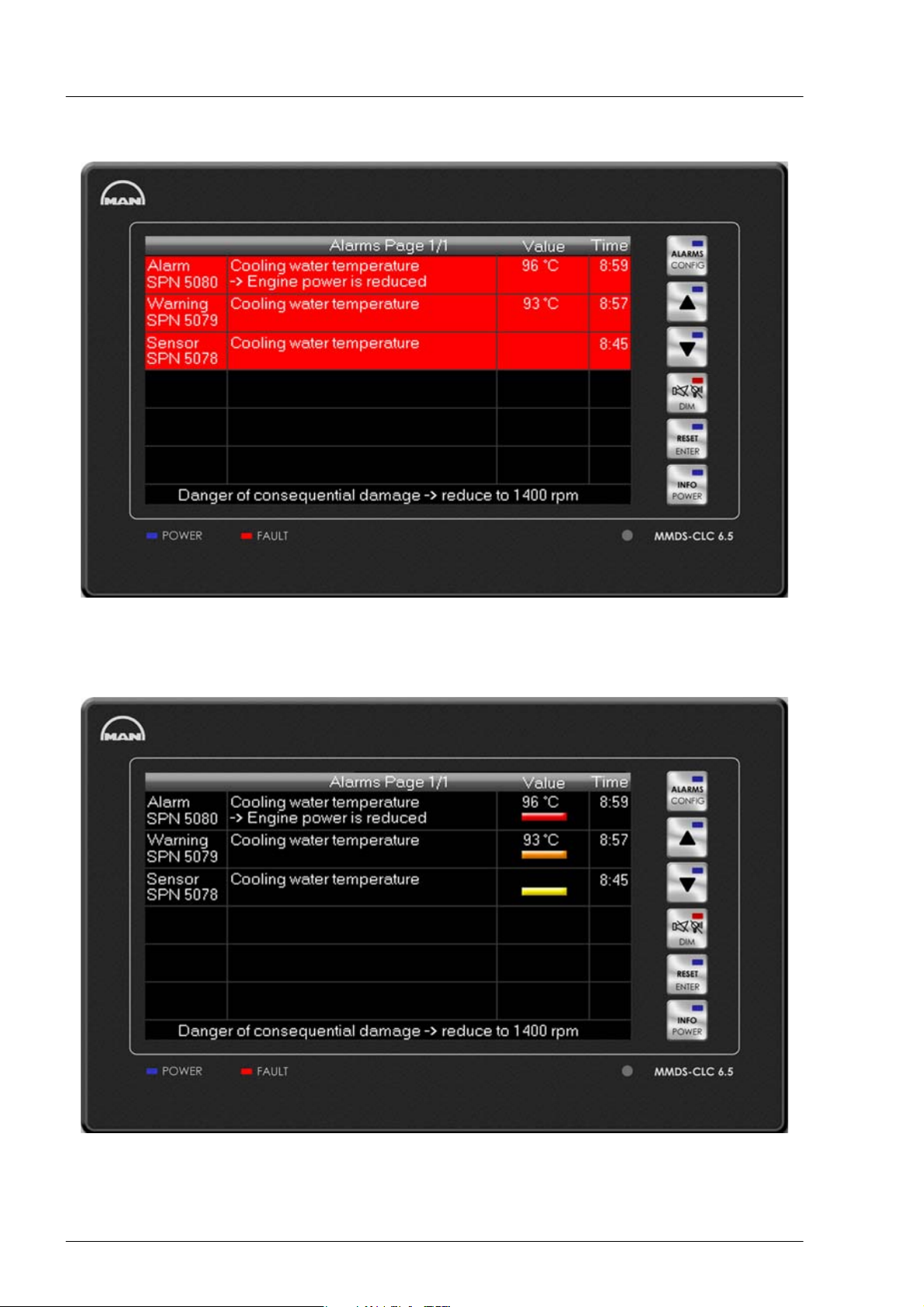
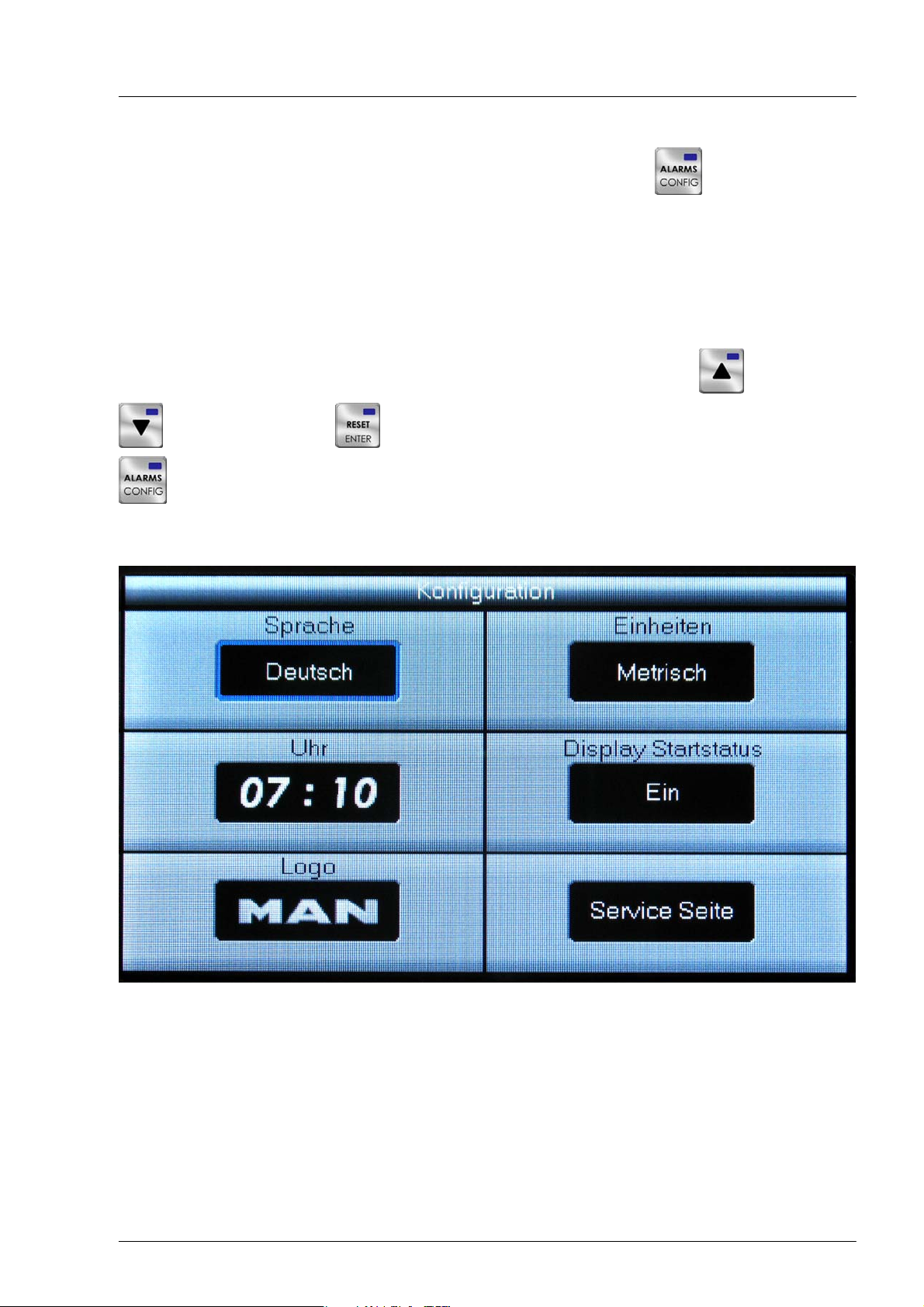
Active alarm page
Commissioning and operation
Acknowledged alarm page
Figure: Alarms table
42
Page 43
Commissioning and operation
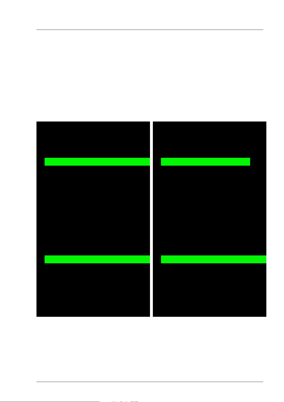
Menu functions
The display unit provides a number of setting options. Activation of the button (1) for approx.
3 seconds activates the menu page. The page contains the following configuration points:
DSelection of the presentation in German, English, Italian, Spanish and French
D Setting the time
D Selection of the logo
D Selection of the display in metric/non-metric units
D Activation of display start status
D Activation of the service page
The menu point in the respective blue marked field can be changed with the buttons (2) and
(3). Pressing the button (5) switches the marking to the next field. Pressing the button
(1) again for approx. 3 seconds causes the set values to be accepted and the menu is exited.
The display switches to the alarm table.
Figure: Menu for setting the display
43
Page 44

Commissioning and operation
Service page
The engine and gearbox data and the alarm conditions of all measuring stations are displayed in a table on
the service page. This page is accessed and exited on selecting the menu item and
changing the page via the buttons (2) and (3).
44
Page 45
Service page
tank
ture
ture
Water level in fuel filter 1
Engine oil pressure
Water level in fuel filter 2
0.0 mV
4.8 bar
0.0 mV
Commissioning and operation
Engine oil pressure at the oil filter
Engine oil temperature
Engine oil level
Crankcase pressure
Coolant temperature
Cool.temperature. in cool.exp.
Cool.press coolant pump
Coolant level in expansion tank
Gearbox oil pressure
?? %
78 _C
?? bar
3.8 V
?? mbar
81 _C
?? bar
0.5 bar
?? bar
Gearbox oil pressure at the filter
12.5 bar
Temp. exh. b. turbine 1
Temp. exh. a. turbine
Failure EDC
Failure SFFR
Temp. exh. b. turbine 2
510 _C
512 _C
420 _C
???? SPN
Remote slow-down
???? SPN
Override
Emergency stop
Alarm throttle control
?? mV
Safety system failure
Safety system alarm
Engine number
Engine type
12345678
D286X LE4XX
Water pre−filter 1
Water pre−filter 2
Oil press. engine
Oil press.eng.b.filtr
Service page 1/2
63 %
80 %
?? m/h
1200 1/min
Engine speed
Throttle
Load/Torque
Relative load
Oil temp. engine
Oil level engine
Crankcase press.
Coolant temp.
Cool. press. exp. t.
25.2 V
120 l/h
Fuel consumption
24.1 V
4.5 bar
4.4 bar
Fuel press. pump1
Pow. supply PIN15
Generator D+
Fuel press. pump2
Cool. press.wat. p.
Coolant level
Oil press. gearbox
Oil press.gbox.b.fil
Exhaust temp. 1
Service page 2/2
30 _C
250 mbar
100 mbar
Fuel press.handp.
Fuel press.return l.
23.5 mV
1200 rpm
Fuel temperature
Inject. pipe leak
Engine speed
Exhaust temp. 2
Exh.temp.aft.turbo
EDC−failure
SFFR−failure
Remote slow down
Override
?? %
78 _C
Oil temp. gearbox
?? _C
Oil level gearbox
Bearing temp.gear
?? bar
?? l/min
Seawater flow
Seawater press.
Emergency stop
Alarm throttle cont
Safety syst. fail
Alarm safety syst.
?? _C
58 _C
25 mbar
Charge air temp.
Seawater temp.
Air intake pressure
?? _C
2.5 bar
Boost pressure
Temp. MMDS int.
Engine number
Engine type
?? _C
30 mbar
Temp. plug X1
Exh. back press.
Engine speed
Throttle lever
Load
Relative load
Fuel consumption
Voltage, term. 15
Fuel press. pump1
Voltage, Gen. D+
Fuel press. pump2
Fuel press. handp.
Fuel temperature
Fuel press. return
Injection pipe leak
45
Engine speed
Gearbox oil tempera-
Oil level gearbox
Bearing temp.gearb.
Seawater flow
Seawater press.
Charge air tempera-
Seawater temp.
Boost press.
Temp. MMDS
Temp. plug X1
Exh. back press.
Page 46

Commissioning and operation
The table has 3 columns for each measuring point. Each entry contains an abbreviation of the designation
of the measuring point, the current measured value and the unit of measurement. The alarm status is
presented via LED symbols. As long as the LED is green the value is in the normal range. If the initial alarm
is reached the colour changes to orange and with a main alarm to red. A flashing LED indicates that the
alarm has not yet been visually acknowledged. If there is a sensor failure, the LED goes out.
Automatic dimming
A photo element is integrated in the front plate of the display unit. This registers the brightness of the envir
onment and the background lighting is automatically adapted to the circumstances. When the light condi
tions get darker the brightness of the display is reduced; if there is more light it is increased.
The automatic dimming can be adjusted to one's own requirements. By simultaneously activating the but
tons (4) and (2) or (3) the darkest point of the display lighting can be set.
46
Page 47
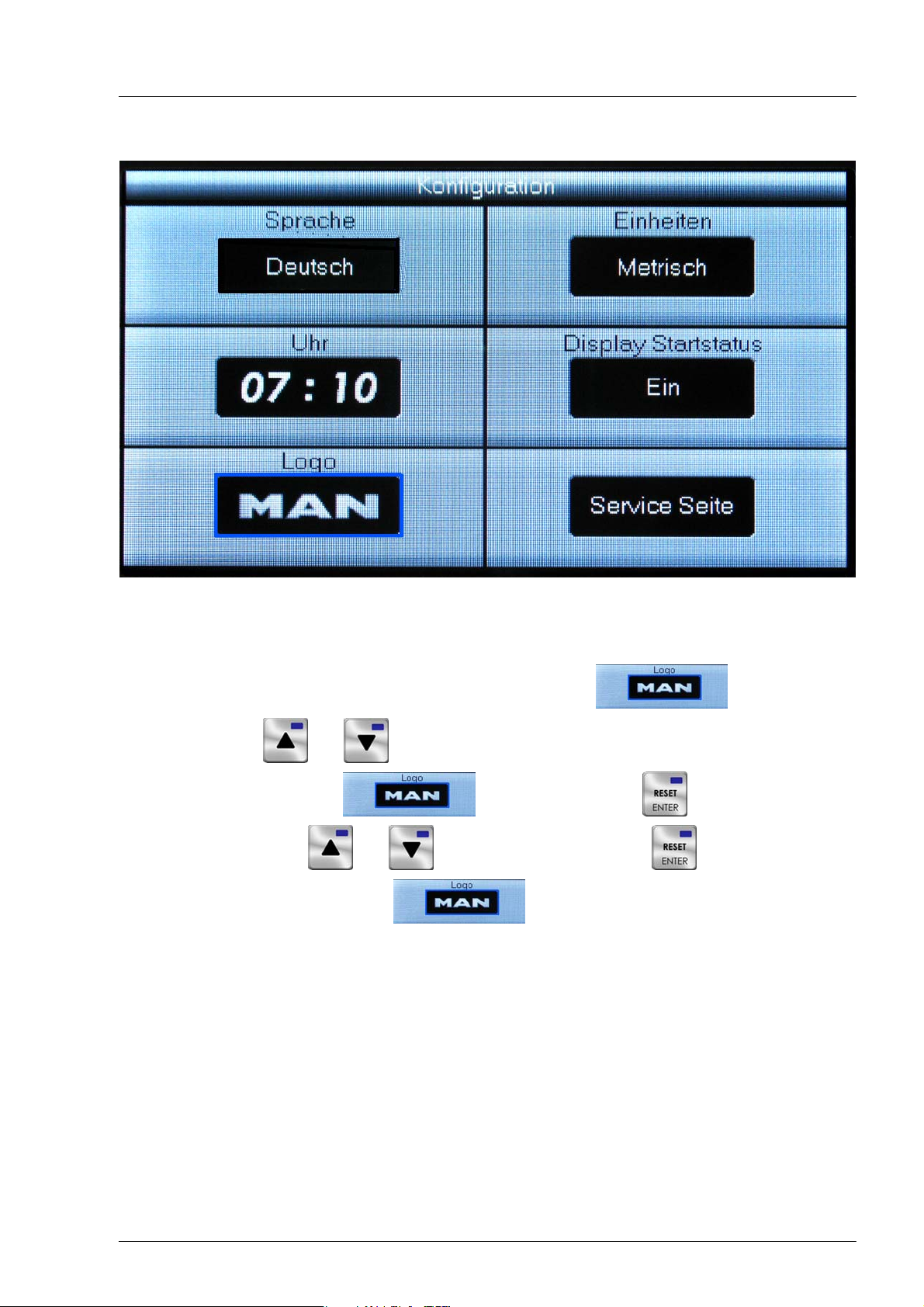
Selection of the logo
Commissioning and operation
Configuration
The logo to be blended in is selected on the logo page. This is displayed at the centre of all pages of the
display. This page is opened or closed on selection of the menu item and changing the
page via the buttons and .
After selection of the menu item by actuating the button an available logo can
be selected via the buttons and . After activation of the button for approx. 3 seconds,
the selection is accepted and the menu is closed.
LED displays
There are two LEDs beneath the display. A green Power" LED is activated by applying the supply voltage.
The red error" LED flashes when there is no communication on the CAN data bus. The displays of the en
gine and gearbox data then all show the value 0".
47
Page 48

Commissioning and operation
4. MMDS-CLC 6.5 ship's alarm display, operation
Introduction
This document describes how the MMDS-CLC 6.5 colour display with MMDS-CLCB 6.5 remote control op
erates and is used as a ship's alarm display. Fitting, mounting and installation are explained in separate in
structions for the unit.
The data monitored on the ship is visualised by the corresponding symbols and displays on the colour dis
play. LED symbols and a table that lists all active alarms with detailed information indicate states of alarm.
For commissioning and service, there is a service page where all the measured values as well as alarm
states of all sensors can be viewed at a glance.
To optimise adjustment to the user's requirements, five languages and display of the data in either metric
or non-metric units can be selected.
Buttons
1
2
3
4
5
6
MMDS-CLC 6.5 ship's alarm display
Operational functions and configuration
The operation of the system and the display adjustment is carried out with the display buttons or the re
mote control MMDS-CLCB 6.5.
The following functions are implemented:
Standard function: Call the alarms table, or browse to further alarm pages.
Additional function: If pressed longer than 5 seconds ⇒ Switches configuration menu on and off.
Standard function: Page back to the previous page
Additional dimming function: On simultaneous actuation of the buttons (4) and (3)
the brightness is reduced.
Additional function in the menu: Change parameter / reduce value.
48
Page 49

Commissioning and operation
Standard function: page up to the next page.
Additional dimming function: On simultaneous actuation of the buttons (4) and (2)
the brightness is increased.
Additional function in the menu: Change parameter / increase value.
Standard function: Acoustic and optical acknowledgement of all monitoring devices connected to
the same CAN-Bus.
Additional dimming function: Adjustment of the brightness on simultaneous actuation of the but
tons and .
Test function: If currently no alarm is on, or if all alarms have previously been optically acknowled
ged, after an actuation for longer than 5 seconds a horn test is carried out, i.e. the internal sum
mer and the horn relay are activated for the duration of the button press.
Standard function: A reset signal is sent via the CAN bus to the engine monitoring and diagnostic
system control unit (engine terminal box) or to a data station. As long as the appropriate criteria
are fulfilled, the engine slow down or shutdown alarms arising are reset.
Additional function in the menu: Accept change and pass to the next parameter.
Actuate the function (approx. 3 seconds): Switch-on and switch-off of the display (display only,
not on remote operation).
Display additional function (long actuation): Info. display appears for approx. 5 seconds
Function
The colour display is automatically activated when the supply voltage is applied. It can then be switched on
and off manually using the “Power" button (6). The other alarm functions such as the alarm relay
and the internal buzzer and the acknowledge button remain operative. There are two screen pages for dis
playing the most important engine and gearbox data. Alarms are displayed in an alarm table.
Graphical display of measured values data
When the device is switched on, page 1 is shown automatically.
Normally, the following is displayed:
Figure: start page with fuel tank levels, bilge status and door monitoring
49
Page 50

Commissioning and operation
a) Fuel tank: (configuration depending on boat type and tank shape)
D Fill level display and digital value
D with approx. 10% of the tank content, an alarm is issued (dependent on customer wish)
b) Water tank: (configuration depending on boat type and tank shape)
D Fill level display and digital value
D with approx. 10% of the tank content, an alarm is issued (dependent on customer wish)
c) Time: can be set on menu page
d) Illustration of the boat type: adapted at the request of the customer to specification.
e) Bilge alarms: with high fill level, an alarm is triggered. (rear, engine room, front end, others are possible)
f) Miscellaneous, e.g. lower bathing ladders, rear gate open (depending on boat type and configuration)
The sensors for the tank and water level as well as the switches for the bilge fill levels and miscellaneous
others are to be connected to the serial substation (e.g. IO 12 ). There must be harmonisation here with re
gard to configuration (tank curves) and possible signal inputs.
Page 2:
Normally, the following is displayed:
Figure: page 2 with digital display elements and bar displays
g) Trim flap position:
here is an instrument in the middle of the display that indicates the trim flap position of the port and star
board trim flaps. For each speed, the trim flap position is suggested by means of a green rectangle. This
proposal is generated from a trim curve integrated in the software that is recorded during the commis
sioning journey.
The trim flap sensors are read in at the serial substation.
h) Rudder position:
The rudder position is displayed in the upper area. The sensors for the rudder position are read in at the
serial substation.
i) GPS speed:
The speed recorded by the GPS is displayed at the right-hand edge of the screen.
The GPS is connected to the serial interface on the back of the CLC ship display.
j) Current fuel consumption:
The fuel consumption is shown at the bottom right.
The value is transferred from the MMDS-CLC 6.5 engine display per data line.
The fuel consumption can only be shown on ships with electronically controlled engines.
50
Page 51

Commissioning and operation
k) Range:
The range of the ship is displayed on the right.
This is a value calculated from the current fuel consumption, GPS speed and current fuel tank content.
The range can be displayed in nautical or standard miles, which can be selected in the menu.
Furthermore, the fuel consumption and e.g. the position of the bathing ladders are often displayed on
page 2.
The (2) and (3) keys can be used to switch back and forth between the two graphical
pages. If the alarm table is activated, the last displayed page is opened.
All sensors and switch inputs connected to the serial substation must be provided by the shipyard and
tested for proper function as well as conformity with the serial substation. Furthermore, the serial substation
must have been configured. The same applies to the GPS system that is connected directly to the CLC
ship.
Alarms
Should an alarm condition occur, an alarm table is automatically displayed. This lists all advance warnings,
alarms and sensor fault alarms. An internal buzzer and the horn relay are activated at the same time.
The collective alarm relay issues a repeat pulse if another alarm was already active. In this way, it is pos
sible to activate a visual call system for each new alarm or to send a telephone message if the ship is not
occupied. Acoustic acknowledgement with the (4) Alarm acknowledgements and reset signals are
sent on the CAN bus to the engine monitoring and diagnostic unit and to all the monitoring devices connec
ted to the same CAN bus. All the equipment thus has the same alarm status.
Alarm display on the graphics pages
On reaching an alarm condition, e.g. full bilge, the associated red LED flashes. By actuating the optical ac
knowledgement button (button (4)) all the flashing displays revert to a continuously lit condition.
When the fault has been eliminated and both acoustically and optically acknowledged (Button (4)),
the alarm display reverts to the “Normal condition".
Sensor failure
All the important sensors are monitored for plausibility. If a sensor error alarm occurs, then the measured
value on the corresponding instrument disappears.
51
Page 52

Commissioning and operation
Alarms table
This table is automatically called when an alarm condition occurs, or can be called manually by pressing
the button (1) It shows all existing alarm messages, i.e. those that have not been acknowledged or
reset. Each entry contains a measuring point text, the current measured value, the time when the alarm oc
curred, the unit of measurement and the type of alarm. The following labels are used for the type of alarm:
Text Meaning
Warning Advance warning
Alarm Alarm
Sensor Sensor fault alarm
A new alarm always appears in the top line. This is highlighted in flashing red until it is visually acknow
ledged. Older messages are automatically displaced one line downwards. If there are more than 10 entries,
further alarm pages are automatically presented for selection. In this event, pressing the “Alarms" button
(1) causes paging on to the next available alarm page. If the first page appears again, or if the dis
play remains unchanged on pressing the button, then no further alarms are present. The numbering of the
alarm pages presented is displayed on the page, lower right. In general a message remains active until it
has been acoustically and optically acknowledged (Button (4)) and the fault has been eliminated.
Figure: Alarms table
52
Page 53

Commissioning and operation
Menu functions
The display unit provides a number of setting options. Activation of the button (1) for approx.
3 seconds activates the menu page. The page contains the following configuration points:
D Setting the time
D Selection of the presentation in German, English, Italian, Spanish and French
D Selection of the display in metric/non-metric units
D Activation of the service page
The menu point in the respective red marked field can be changed with the buttons (2) and
(3). Pressing the button (5) switches the marking to the next field. Pressing the button
(1) for approx. 3 seconds results in the set values being accepted and the menu is closed.
The display switches to the alarm table. The selection of the language has no influence on the menu and
the service page. These pages are always displayed in English.
Figure: Menu for setting the display
53
Page 54

Selection of the logo
Commissioning and operation
Configuration
The logo to be blended in is selected on the logo page. This is displayed at the centre of all pages of the
display. This page is opened or closed on selection of the menu item and changing the
page via the buttons and .
After selection of the menu item by actuating the button an available logo can
be selected via the buttons and . After activation of the button for approx. 3 seconds,
the selection is accepted and the menu is closed.
LED displays
There are two LEDs beneath the display. A green “Power" LED is activated by applying the supply voltage.
The red “error" LED flashes when there is no communication on the CAN data bus. The displays of the ship
data then all show the value “0".
54
Page 55

Commissioning and operation
5. MMDS-CMS display device
The visualisation of engine operating data, general ship's messages and alarms is an important part of
modern alarm and safety systems on ships. The amount of information is steadily increasing and must be
registered and evaluated quickly. Alarms and / or warnings are to be recorded and reported quickly and
precisely. Clear and user-friendly displays are a precondition for safe operation of any ship.
The MAN Monitoring System represents a new component of the proven alarm, safety and diagnostic sys
tem MMDS, which offers a variety of new functions and display formats. The PC-based system is used to
display operating data of several engines and general ship messages.
The 10" / 15" MMDS-CMS 10 / 15 TFT monitor is part of the system. Data that has previously been pro
cessed by the corresponding software is shown on the display. The software is controlled using integrated
function keys that are located on the left of the display. The assigned functions are shown on the left edge
of the display. There is a choice of various forms of display. These can be pages with digital displays, ana
logue instruments, visual engine graphics and tabular displays. There are also two keys at the bottom right
for visual and acoustic alarm acknowledgement. The keys above these are for setting the display by means
of an “on screen display" menu.
55
Page 56

Commissioning and operation
Function and operation
Display functions
The display is switched on and off using the Power button (top right). Underneath this, there are four sys
tem keys for adjustment of the display illumination and for maintenance of the display. Usually, only the ar
row keys are important. The “Menu" and “Store" keys are for controlling the OSD menu.
Function: Switching the display on and off.
Functions: Activation and deactivation of the OSD menu and switching to the next
higher menu level.
Standard func
tion:
Standard func
tion:
Functions: Selecting menu items and saving parameter values.
Software operation
The MMDS-CMS 10/15 monitor serves to display and control visualisation software that is installed on the
PC. This software is adapted to the overall system and is explained in a system description. Ten function
keys are arranged on the left of the display for operation of the software. The assigned functions are shown
at the edge of the display.
For the control of software functions, there are also two keys at the bottom right for visual and acoustic
alarm acknowledgement.
Decrease display brightness.
Additional functions if the OSD menu is shown: shifting the selection field
for the menu items upwards and increasing parameter values.
Increasing display brightness
Additional functions if the OSD menu is shown: shifting selection field for
the menu items downwards and decreasing parameters.
Example of a function key with the assigned function to call up analogue
display.
Standard function:
Additional function:
Standard function:
Additional function:
Acoustic acknowledgement of all monitoring devices contained in the
system.
If a Windows communication box appears, this key (TAB) enables
selection control.
Visual acknowledgement, which means that all flashing alarms switch to
continuous light if they have previously been acknowledged acoustically.
All other monitoring devices contained in the system are acknowledged
as well.
If a Windows communication box appears, this key (ENTER) enables
acknowledgement.
56
Page 57

Commissioning and operation
Software description
Introduction
Processing engine data, general ship data and alarms is an important part of modern alarm and safety sys
tems on ships. The amount of information is steadily increasing and must be registered and evaluated
quickly.
The MAN Monitoring System MMDS-CMS belongs to the Alarm, Safety and Diagnostic Unit MMDS.
It offers a variety of functions and types of display, which are mainly defined by the visualisation software.
It is fully installed and configured on the compact PC MMDS-CMS S which is part of the system.
Measured values and alarms are displayed in different forms on the monitoring system. Alongside a preset
page with displays of analogue or digital instruments, there is a page that can be freely configured by the
user. In addition, the engines are represented graphically. In the event of a fault, the source of the problem
can be recognised easily. A further special feature is the dynamic display of speed-dependent variables.
The limit value changes directly with the speed so that the distance between an actual value and the cor
responding alarm limit value is easily recognisable at any time. All alarm and measuring point lists are avail
able in tabular form. The displays are operated using the integrated function keys or by means of an ex
ternal mouse or trackball.
This documentation is intended to make the user acquainted with the operation of the software and to
provide an overview of the system at a glance. Please note that this description is a minimum configuration
of the monitoring system. Extension options are documented separately. The devices belonging to the sys
tem are also documented extensively in the individual device descriptions.
57
Page 58

Commissioning and operation
Scope of services
The monitoring system registers, evaluates and displays engine and gearbox data of MAN ship's diesel en
gines. The measured values are registered via the MMDS diagnostic units, one of which is placed each of
the engine terminal boxes. Data interchange between the devices takes place via the separate CAN bus
lines, CAN Engine 1 and CAN Engine 2. The compact PC, which is part of every display, processes the
data and makes it available on a CMS 15" / 10" display with the help of visualisation software.
Display
The data is shown on the 10"/15" display MMDS-CMS 10" or the smaller MMDS-CMS 15". Ten function
keys are integrated in each of the monitors. This enables functions such as page selection or scrolling.
On connection of mouse and keyboard, one of the pages can be freely configured. On the Custom page,
the selection of data and its displays can be adapted to the user's needs by means of a few mouse-clicks.
Extension options
The MMDS-CMS alarm system can be extended to form a comprehensive ship and engine alarm system.
A large number of analogue and binary sensors can be integrated on connection of one or more data sta
tions (e.g. MMDS IO12) in order to, e.g., monitor the filling levels of fuel tanks or the condition of position
lanterns. Further route-specific information can be calculated by connecting a GPS receiver that uses
sensor data, for example the range resulting from the current fuel consumption and speed.
58
Page 59

Operation
Commissioning and operation
1
1
2
3
4
5
6
7
2
3
4
5
8
9
10
The displays are activated automatically when the power supply is switched on. They can be switched on
and off individually by pressing “Power" button Ê.
The computers can be switched on and off when the power supply is switched on. The startup procedure of
the operating system Windows XP, as well as of the visualisation software, takes approx. one minute and
is visible on the displays.
6
7
Control with the function keys
The (1) - (10) function keys to the left of the display are used to control the software. Operation is dynamic,
i.e., the assigned functions change depending on the page displayed. The currently possible functions are
explained in a specifically assigned section of the display located to the right of each key. Insofar as a field
is empty, the assigned key does not have any function.
Menu functions are selected using the function keys or per mouse-click on the menu text. The following list
shows all the functions available in the program. They can be used to select a specific page, to scroll within
tables or perform other functions.
Function: opens the start page, which exclusively shows digital displays (see page 62,
Main Menu).
Function: opens a page which displays data as analogue instruments (see page 64,
Analogue display).
Function: opens a page which displays data digitally (see page 65, Digital display).
Function: opens a page on which the user can customise the display interface ac
cording to his / her own wishes (see page 67, User-defined display).
59
Page 60
Commissioning and operation
Function: opens a page which shows visual representations of the engines with the
corresponding measured values (see page 69, Visual engine display).
Function: opens the alarm screen. Here, the acknowledged and unacknowledged
alarms are displayed in tabular form (see page 73, Tabular display of alarms).
Function: opens the measuring point lists. Here, all measuring points are shown in
tabular form (see page 70, Measuring point list).
Function: opens the settings page. Here, the clock, the unit system and other options
can be set.
Function (only available in the measuring point list, alarm table or settings page): swit
ches over to the last visualisation mode shown.
Function (only available on settings page): selects the next adjustable element.
Function (only available on settings page): selects the previous adjustable element.
Function (only available on settings page): increases value of the selected element.
Function (only available on settings page): decreases value of the selected element.
Function: (only available in the alarm table): scrolls up in the alarm table.
Function: (only available in the alarm table): scrolls down in the alarm table.
Function: (only available in the measuring point list): opens the measuring point list for
the port engine.
Function: (only available in the measuring point list): opens the measuring point list for
the starboard engine.
Function: (only available in the measuring point list): scrolls up in the measuring point
list.
Function: (only available in the measuring point list): scrolls down in the measuring
point list.
60
Page 61
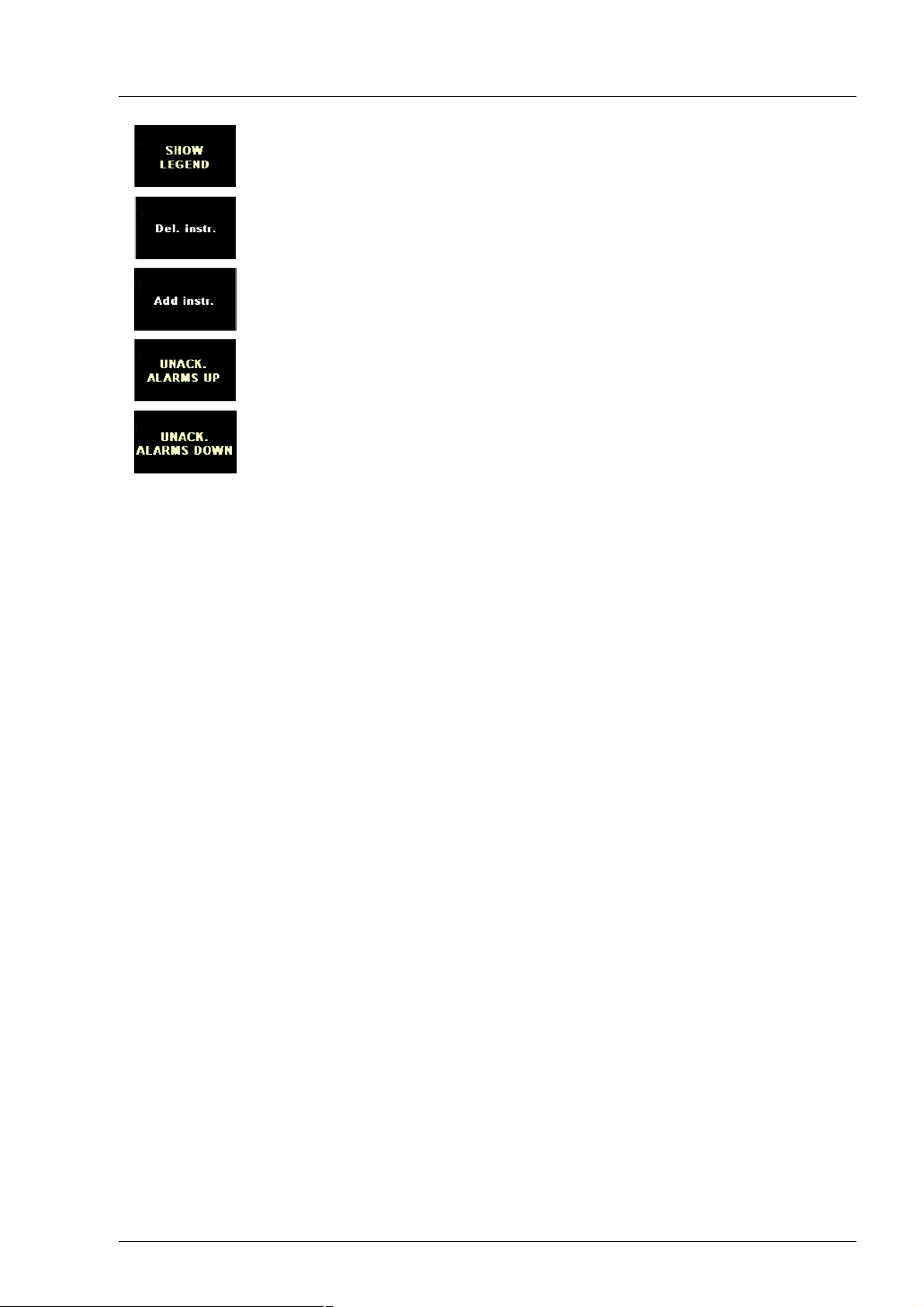
Commissioning and operation
Function: (only available in the measuring point list or in the alarm table): shows / hi
des legend with explanations for the table column “Kind of alarm".
Function: opens the instrument selection menu. An instrument selected here is dele
ted, if present. (only available on the “Custom" page. The button can only be selected
using the mouse).
Function: opens the instrument selection menu. An instrument selected here is in
serted or the form of display is changed (only available on the “Custom" page. the but
ton can only be selected using the mouse).
Function: scrolls up in the table of unacknowledged alarms.
Function: scrolls down in the table of unacknowledged alarms.
OSD menu
The Ë - Î keys to the right of the display have general functions for setting the display (on-screen menu).
Brightness adjustment
The backlighting of the display can be dimmed. On operation of the Ì or Í keys, a bar display appears
which indicates the current brightness in %. It is controlled by holding down the keys. The brightness is re
duced using the Ì key and increased using the Í key.
Acknowledgement
The Ï + Ð keys on the bottom right are for acknowledgement of alarms. Pressing the Ï key acoustically
acknowledges all monitoring devices contained in the system.
The Ð keys visually acknowledges all alarms that were previously acknowledged acoustically, i.e. flashing
alarms change to a permanent signal. All other monitoring devices within the system are also acknow
ledged in this way.
Windows communication box
The Ï + Ð keys also have additional functions for Windows control. Should a Windows communication box
appear, the Ï key enables selection control. The function corresponds to the “Tab" key of a PC keyboard.
The Ð key is used for confirmation and corresponds to the “Return" key.
Data display
The data is visualised on 5 different graphical pages, a page with tabular measuring point lists and an
alarm table.
An engine has a total of 35 measuring points. Six measuring points per engine can be enabled on commis
sioning.
61
Page 62

Commissioning and operation
Main menu (start page)
After switching on the system, the start page is shown first of all. The start page can be called up via the
“MAIN MENU" function from any other page. The most important measured values of both engines are
summarised here and displayed in large digits. The unacknowledged alarms, as well as the date and time,
can be found in the lower section.
Description of function keys
for software operation
Area for depiction of port en
gine measuring points
Area for depiction of starboard
engine measuring points
Date Table of all unacknowledged alarms Time
Figure: start menu
62
Page 63

Commissioning and operation
Settings page (Adjustments)
The time and units (metric or imperial system) are set on the settings page. The display of the mouse
pointer, as well as the commissioning sensors, can be enabled and disabled here.
This page is only accessible from the “Main Menu" page. Pushing the F7 key opens the settings page.
Values are set using the F5 and F6 function keys. Pushing the F5 (+) key increases the selected value by
one; pushing the F6 key (-) reduces the value accordingly. The appropriate key can also be held down to
accelerate setting of the time.
The value to be set next is activated with the “NEXT ELEMENT" (F2) button. The “PREV ELEMENT" (F3)
button is used to move back one value. The currently selected value is framed in red. Switching back to the
main menu page is possible by means of the “BACK" button after completion of the settings. The set val
ues are automatically adopted and stored.
Setting the date and time
Mouse indicatorvis
ible / not visible
Showing / hiding com
missioning sensors
Figure: settings page
63
Changing the unit
system
Page 64

Commissioning and operation
Analogue display
This page is opened using the “ANALOGUE" function. The most important engine and gearbox data is
visualised as instrument dials in this display. The battery voltage and current fuel consumption are shown
digitally. The unacknowledged alarms, as well as the date and time, can be found in the lower section.
Description of function
keys for software oper
ation
Area for depiction of port en
gine measuring points
Area for depiction of star
board engine measuring
points
Table of all unacknowledged alarms
Figure: Analogue display
64
Page 65

Commissioning and operation
Digital display
This page is opened using the “DIGITAL" function. Important engine and gearbox data is shown here as
bar displays. This form of representation enables easy evaluation of the registered data, including how far
they are away from limit values, as well as their relationship to other values.
Battery voltage, current fuel consumption and total operating hours for both engines are displayed digitally.
In a similar way to the other graphical pages, the table with the unacknowledged alarms is located in the
lower area.
Description of function
keys for software oper
ation
Area for depiction of port en
gine measuring points
Area for depiction of star
board engine measuring
points
Table of all unac
knowledged alarms
Battery voltage
Rel load
Fuel consumption
Total engine op
erating hours
Figure: Digital display
65
Page 66

Commissioning and operation
User-defined display
The user can configure the instrument range as desired in the user-defined display. All instruments can be
defined as regards their size and type of representation. Important measuring points can thereby be high
lighted visually. The instruments are available in different forms of display. For example, exhaust gas tem
peratures can be represented as thermometers or instrument dials; the speed can be shown as an instru
ment dial or meter.
Binary engine alarms are not available in this display. Alarms are, however, listed in the table of unacknow
ledged alarms, as on all other pages.
Description of function keys
for software operation
Configurable area
Table of all unacknowledged alarms
Figure: user-defined display (example)
66
Page 67

Commissioning and operation
Configuration of user-defined display
A mouse or trackball and a keyboard must be connected to the MMDS-CMS S compact PC in order to con
figure this display. To insert or delete an instrument, click on the softkeys to open the selection menu on
the softkeys (the F7 and F8 keys are disabled here, as a mouse or another pointer devices is required).
Various instruments are available in this menu for the individual measuring points. Selecting an instrument
adds or deletes it.
Figure: opening the selection menu
A mouse click on the point is used to configure an instrument.
Figure: click points of the individual instruments
67
Page 68

Commissioning and operation
To shift an instrument, click to select it and drag with the mouse button pressed (drag and drop).
Figure: shifting an instrument
The following configuration window appears on clicking an instrument while holding down the [Shift] key.
The size of an instrument can be adjusted here between 250 and 400 pixels. To do this, the orange indic
ator on the scale is dragged with the mouse or the value is entered directly into the adjacent field. The
changes are accepted and the configuration window is closed by clicking the “DONE" button.
Figure: the configuration window
68
Page 69

Commissioning and operation
Visual engine display
In the graphical display, the exhaust gas temperatures are shown at the relevant installation positions of
the sensors. Other measuring points and binary alarms are located in the lower half of the page shown.
The instrument area is divided into two halves. The measuring points for the starboard are arranged in the
right half; those for the port are shown in the left half.
As on all pages, the unacknowledged alarms are shown in the lower part.
Selection area for
other pages
Display area of
starboard engine
Display area of
port engine
Figure: Visual engine display
69
Page 70

Commissioning and operation
Display of all measuring points
List of measuring points
This display shows tables of all the measuring points available in the system. The “ENGINE PORT" and
“ENGINE STBD" keys are used to select the list for the respective engine. This view can be opened from
all other pages by pressing the “MEASURING POINTS" key. The complete list can be viewed by pressing
the “TABLE UP" or “TABLE DOWN" keys. Selection of the “BACK" key opens the last activated view. A le
gend that explains of the abbreviations can be hidden or shown using “SHOW LEGEND" button.
As on all pages, the unacknowledged alarms are shown in the lower part.
Figure: table with all measuring points and legend shown
70
Page 71

Commissioning and operation
Structure of the table
The columns “Measuring point“, “Unit", “Value" and “Kind of Alarm" in the tabular display mean:
Measuring point Contains the designation of the measuring point
Unit Contains the unit of the measurement variable
Value Contains the current measured value
Min / Max Identification of the type of monitoring of the limit value
Kind of Alarm The three alarm stages: “Sensor failure", “Warning" or “Main alarm"
List of all measuring points
Each of the two engines has analogue and binary sensors. The measured values are monitored and evalu
ated by the MMDS diagnostic unit. The data is made available to the PC system via CAN BUS.
Identification of alarm monitoring
The following identifiers are distinguished at “Min / Max":
D NORM Normal state
D XAExternal alarm
D FAULT Failure alarm
D TIAH Temperature limit value exceeded
D TIAL Temperature limit value undershot
D DTIAH Positive temperature deviation
D DTIAL Negative temperature deviation
D TAH Temperature too high (binary alarm)
D TAL Temperature too low (binary alarm)
D PIAH Pressure limit value exceeded
D PIAL Pressure limit value undershot
D DPIAH Positive pressure deviation
D DPIAL Negative pressure deviation
D PAH Pressure too high (binary alarm)
D PAL Pressure too low (binary alarm)
D LIAH Level limit value exceeded
D LIAL Level limit value undershot
D LAH Level too high (binary alarm)
D LAL Level too low (binary alarm)
D IND Display (analogue input, no limit value control, but failure display)
D BLC Blocked alarm (measuring point blocked by another measuring point)
71
Page 72

Commissioning and operation
Alarm and limit value display
Dynamic limit value display
Limit values depending on the speed are represented dynamically by the monitoring system. In the follow
ing illustration, the speed was changed at constant oil pressure. The rise in the limit value can be recog
nised with increasing speed.
Figure: dynamic limit value display on the oil pressure gauge
Graphical alarm display and alarm acknowledgement
When a state of alarm has been reached, the corresponding instrument starts flashing. In the event of an
alarm, the instrument flashes until the alarm state is acknowledged. Two keys to the right of the display are
used for the acknowledgement.
Function: acoustic acknowledgement or deactivation of the internal horn. All monitoring devi
ces within the system are acknowledged on operation.
Function: Visual acknowledgement, which means that all flashing alarms switch to conti
nuous light if they have previously been acknowledged acoustically. All monitoring devices
within the system are acknowledged on operation.
Figure: various versions of the “Coolant temperature" instrument flashing in the event of an alarm
72
Page 73

Commissioning and operation
Tabular alarm display
There is a graphical alarm display in parallel to a tabular display. There is an “Alarms" table in the display
that contains all alarms and the “Unacknowledged alarms" table with all unacknowledged alarms. Both can
be seen in the alarm table. This view is opened from any other page using the “ALARMS" key. An excerpt
from the table with the unacknowledged alarms is also found on all other pages.
Figure: active alarm table
Structure of the table
The columns “Measuring point", “Unit", “Value", “Time", “Date" and “Kind of alarm" in the tabular display
mean:
Measuring point Contains the designation of the measuring point
Value Contains the measured value at the time of the alarm
Unit Contains the unit of the measurement variable
Time Contains the time the alarm occurred
Date Contains the date the alarm occurred
Min / Max Identification of the type of monitoring of the limit value (see chapter
“Identification of alarm monitoring" on page 71)
Kind of Alarm The three alarm stages: “Sensor failure", “Warning" or “Main alarm"
The control options on the alarm table page are identical to those on the measuring point list.
73
Page 74

Commissioning and operation
Alarm table and alarm acknowledgement
Each new alarm flashes initially in the top line. Existing alarms move down one line. On acknowledgement,
the flashing display of all alarms turns into constant light. If there are more alarms than can be represented,
the user can use the “ALARM TABLE UP" and “ALARM TABLE DOWN" keys to scroll up and down.
When the source of an alarm has been removed and the alarm has been acknowledged, it is deleted from
the alarm table. Two keys to the right of the display are used for the acknowledgement.
Function: acoustic acknowledgement or deactivation of the internal horn. All monitoring devi
ces within the system are acknowledged on operation.
Function: Visual acknowledgement, which means that all flashing alarms switch to conti
nuous light if they have previously been acknowledged acoustically. All monitoring devices
within the system are acknowledged on operation.
Table of unacknowledged alarms
The first alarm that occurs is shown in the top line. All following alarms initially appear in the second line
and move one line down as other alarms follow. The first alarm can always be found in line 1, simplifying
the evaluation of the cause of further alarms. If there are more alarms than can be displayed, the complete
list of unacknowledged alarms can be called up using the F9 and F10 keys. The display remains active until
the alarms have been acknowledged. All alarms in the table are deleted on acknowledgement. The “Visual
ackn" and “Acoustic ackn" keys are used for acknowledgement.
74
Page 75

Commissioning and operation
6. Drive lever control Marine Power Control (MPC)
Danger:
For safety reasons a separate, functioning red emergency-stop button for each engine must be in
stalled at every bridge (the engine must stop immediately when the button is pressed once).
At the request of the shipyard or customer, it is possible to purchase from MAN an electronic drive lever
control system made by Bosch-Rexroth, model Marine Power Control.
This control system has plug connections specially configured for MAN.
Command master
Danger:
Incorrect function due to damaged control head!
Humidity may ingress into the damaged control head. The vessel can then no longer be controlled
correctly.
Inspect the control head for visible damage before every operation of the vessel.
Do not set out with a damaged control head.
Caution:
Danger! Do not secure or lean on the lever.
Undesired engine speed change and breakage of the lever is possible.
Never use the control head or the lever as a hand hold.
Do not lean against the control head.
Caution:
Damage can result from pointed objects!
Destruction of the covering film is possible. Dampness can then ingress and lead to control fault
functions.
Do not use pointed objects to operate the control buttons.
Do not cover the control head in use with a protective hood.
75
Page 76
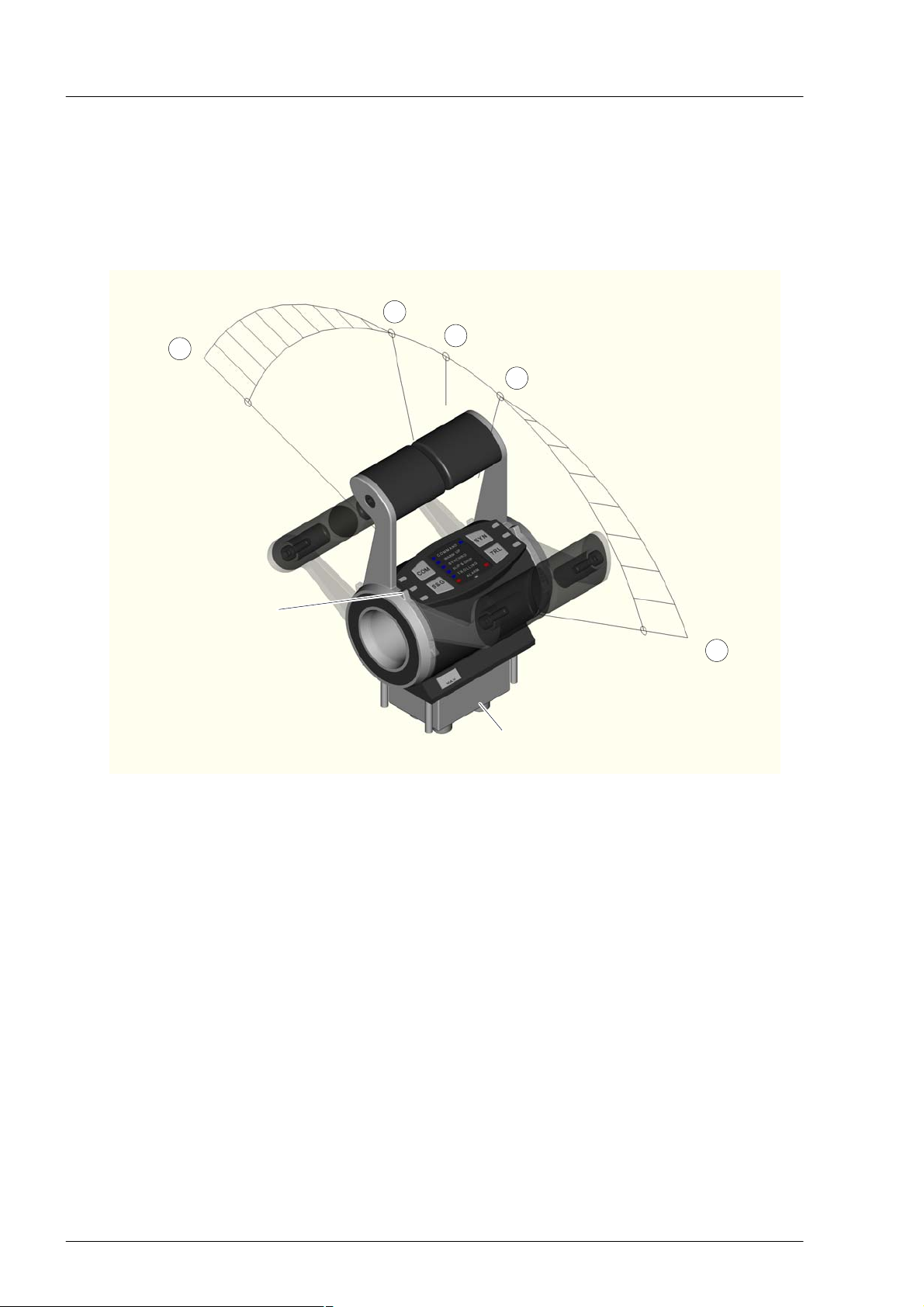
Commissioning and operation
The control head is used to control engine speed and the gearbox.
The operation takes place via the control lever and four buttons.
On twin engine installations the left control lever operates the port engine and gearbox and the right lever
the starboard engine and gearbox.
On single engine installations the handle on the control lever is the universal control.
Function
Infinitely variable
speed adjustment
3
Max. speed
Control panel
Gearbox ahead
(lock)
Ahead range
Neutral
2
(lock)
1
Gearbox astern
(lock)
2
Astern range
Infinitely variable
speed adjustment
3
Max. speed
Acoustic
signalling device
“Neutral" (lock) position (1)
In this position, the gearbox clutch is disengaged and the power unit is idling. Each time the “Neutral-posi
tion" is reached, the control system indicates this acoustically by means of a short “beep-tone".
76
Page 77
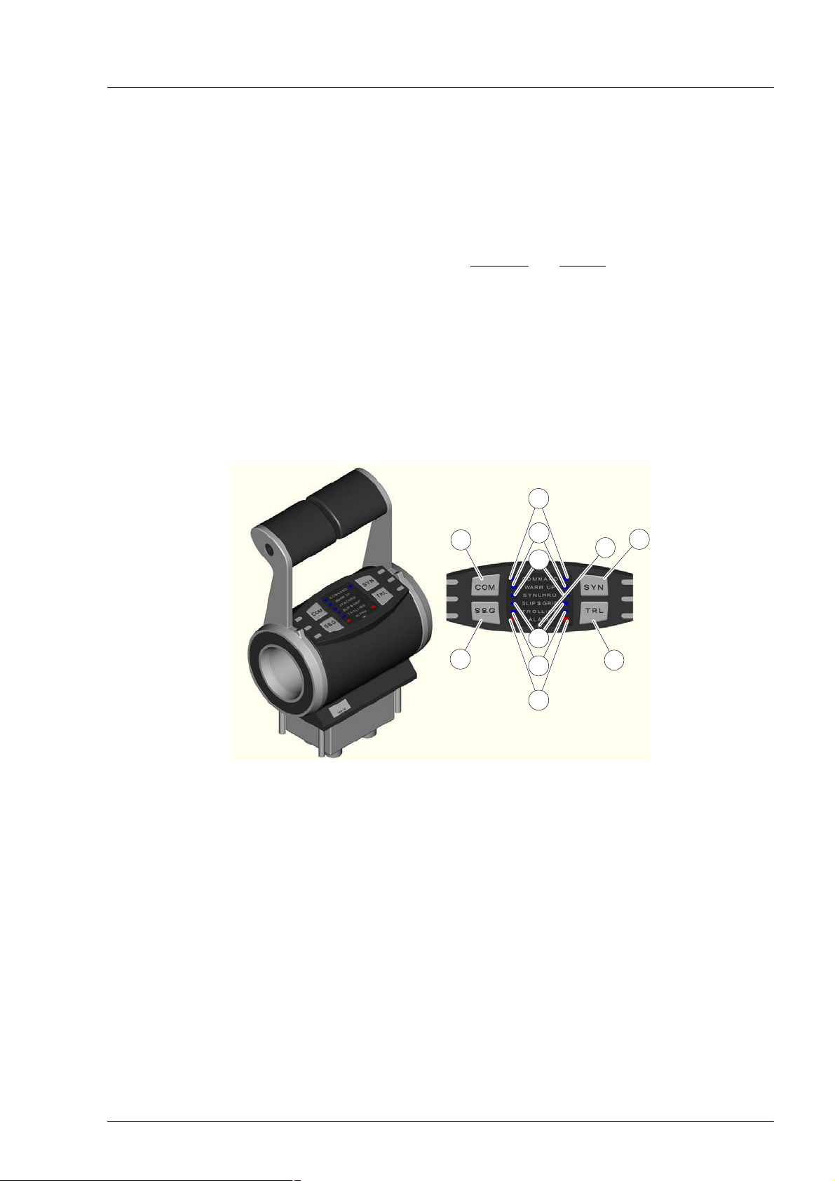
Commissioning and operation
“Gearbox forwards / reverse" (lock) position (2)
In this lever position, two different functions are possible.
1. Standard function:
The gearbox clutch is engaged to Forwards" or Reverse"; the power unit is idling.
2. “Increase engine speed" function
The Increase engine speed" function is set. The engine speed of the power unit is raised prior to enga
ging the clutch and after disengaging the clutch it is lowered again to idling speed. Between the clutch
engaging operations, individual delays (waiting periods BEFORE and AFTER clutch engaging) can be
set.
“Maximum engine speed" position (3)
Position (3) shows the maximum engine speed" for the “Forward and Reverse Range". Between positions
(2) and (3) the engine speed can be set variably. The gearbox clutch is engaged to “Forward" or “Reverse".
Control panel - Control head for twin engine installations
(1) Button COM
(2) Button SYN
(3) Button TRL
(4) Button S&G
(5) Brightness sensor
6
1
7
8
9
4
10
11
(7) LED WARM UP
(8) LED SYNCHRO
(9) LED TROLLING
(10) LED SLIP & GRIP
(11) LED ALARM
2
5
3
(6) LED COMMAND
77
Page 78
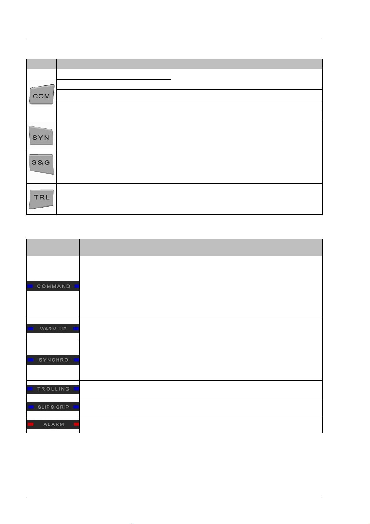
Commissioning and operation
Description of buttons
Button Function see
Request command “Activate control console", see page 79
Accept command
Engine warm up “Engine Warm Up", see page 81
Acknowledge alarm “Acknowledge alarm", see page 86
Adjust brightness of LEDs “Adjust brightness" see page 85
“Change control console", see page 80
Automatic synchronisation of the en
gine speeds for twin engine layouts
Switch on and off the “Slip & Grip" ope
rating function
Switch on and off the “Trolling" opera
ting function
Description of LEDs
LED Function
Flashes slowly:
Command requested,
Handover not possible
Flashes rapidly:
Command requested,
Handover possible
Continuously lit:
Command active
Continuously lit:
Engine speed adjustment possible
Gearbox “Neutral"
Flashes:
Speed synchronisation is in stand-bymode
Continuously lit:
Speed synchronisation active
“Synchronise engine speed", see page 81
Switch “Slip & Grip on and off", see page 85
Switch “Trolling on and off", see page 84
Separate display for port and starboard
engine
yes
yes
no
Continuously lit:
Trolling active
Continuously lit:
Slip & Grip active
Continuously lit:
Alarm
no
no
yes
78
Page 79
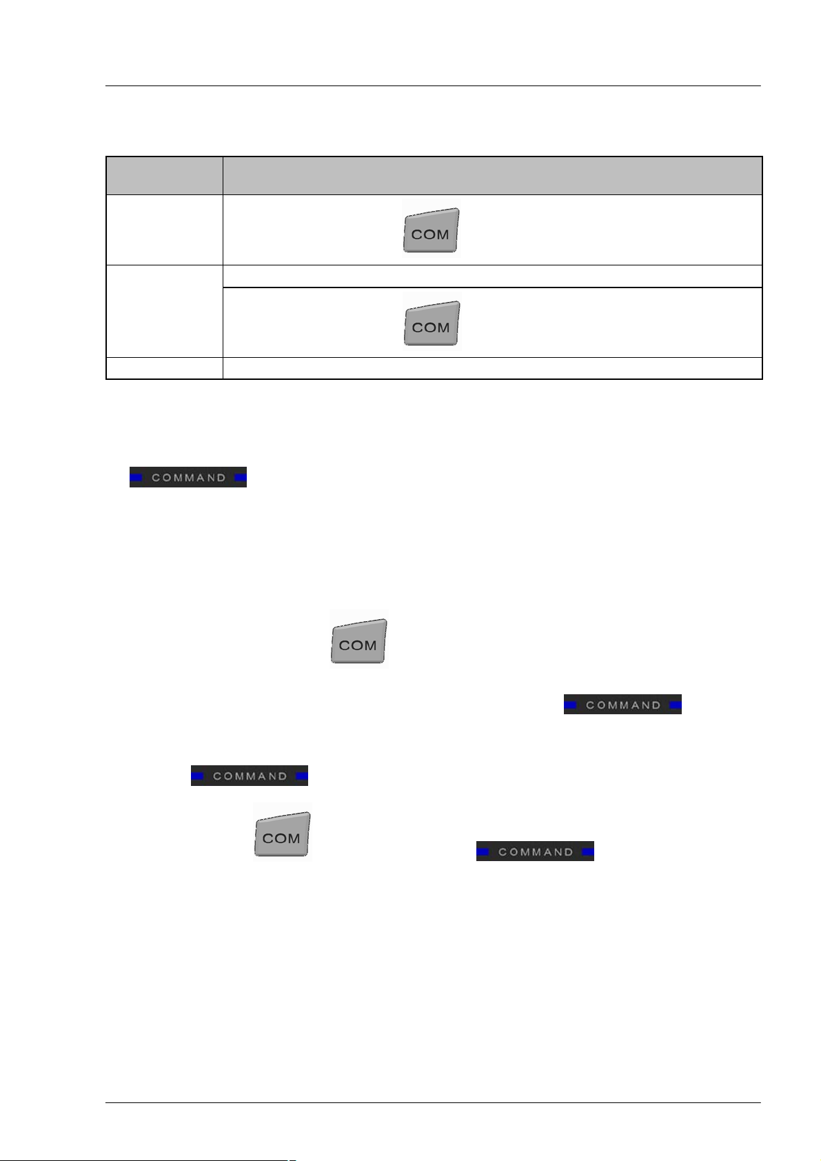
Commissioning and operation
Description of acoustic signal transmitter
Warnings and alarms can be reproduced via the acoustic signal transmitter..
Interval signal
tone
fast actuation of the button Handover of the control console possible
slow
Continuous tone Fault alarm of the connected control Alarm
Activate control console
If the control is switched on via the master switch, first all control consoles are initialised.
This is indicated by a slow flashing LED on each control console.
D
D and an unbroken acoustic signal.
During the initialisation
D the control consoles are inactive and
D the vessel cannot be controlled from any control console.
Event Meaning
Initialisation of the connected control Handover of the control console is requested
actuation of the button Handover of the control console not possible
Select control head
Select the control head by actuating the button.
TheLEDs and signal tone stop on all other control consoles.
If the levers are not in the “Neutral“ position, the LEDs continue to flash and the sig
nal tone remains the same.
If necessary, place the lever in the “Neutral" position.
The LEDs now flash quickly and the signal tone is faster.
Extinguish the LEDs by pressing the button again .
The control console is active and the engine can be started.
79
Page 80

Commissioning and operation
Change control console
Note:
The control console can only be changed, when no directional change is taking place in the gear
box.
Current control console Control console to accept control
"Ahead range" “Ahead" range or “Neutral"
“Neutral" range Neutral
Astern range “Astern" range or “Neutral"
In order to activate a passive control console, the control head must be selected and then the selection
confirmed. The active command remains with the active control console, until the selection is confirmed.
Select the control head by actuating the button.
If the levers are not in the “Neutral position, the LEDs flash slowly and the signal
tone is likewise slow.
Adjust the lever of the control head according to the table.
The LEDs flash quickly and the signal tone is likewise fast.
Confirm the control head by pressing the button again.
The LEDs go out and the signal tone stops.
The requested control console now has active command, the previously active control console is passive.
If the button to confirm the change of command is not pressed within 15 seconds, the change of
control console terminates.
Note:
If the “COM" button to confirm the change of command is not activated within 15 seconds, the
change of control console terminates.
80
Page 81

Commissioning and operation
Engine Warm Up
Caution:
Do not exceed the permissible highest engine speed.
Note:
On vessels with twin engine drive the port and starboard engines can be warmed up independ
ently.
Start the “Warm Up" function
1. Set the respective control head in the “Neutral“ detent.
2. Press and hold the button.
3. Set the respective control head lever in the “Ahead" or “Astern" position.
4. Release the button.
The “Warm Up" function is activated. The respective LED lights permanently.
The engine speed corresponds to the lever setting, the gearbox remains disengaged.
Exit the “Warm Up" function
The “Warm Up" function is stopped by moving the lever to “Neutral".
Synchronise engine speeds
On twin engine layouts the option exists to synchronise the speeds of the propulsion engines.
The “Synchro" can be used
D to control all engines at the same engine speed,
D or to set the engine speed of all engines using one lever (Master)
In this instance the master system takes over the control of the slave system.
Note:
The engine speeds can also be synchronised in the “WARM UP“ mode. This is useful, for ex
ample, when it is required to apply identical control of the engines with reference to the tachomet
ers.
81
Page 82

Commissioning and operation
Control engines at the same engine speed
1. Set both levers in the range between “Ahead" and “Full ahead" (max. deviation of the levers from each
other 10%).
2. Press button.
Both engines are regulated to the same engine speed. The LEDs light.
Note:
If the levers are moved out of synch. with each other by more than 10%, then the “SYNCHRO"
mode reverts to Stand-by mode. As soon as the levers are again positioned less than 10% away
from each other, the synchronisation becomes effective again.
Adjust engine speeds with a single lever
1. Position the lever in the “Ahead" detent.
2. Press button.
The LEDs light. Both engines are engaged at idle.
Increase speed of all engines:
3. Push the lever of the master system forward.
The LED of the master system remains lit, the LED of the slave system goes out.
Note:
If the speed of the slave system is increased, the “SYNCHRO" function reverts to the Stand-by
mode. As soon as the levers are again positioned less than 10% away from each other, the syn
chronisation becomes effective again.
and
1. Set both levers in the range between “Ahead" and “Full ahead" (max. deviation of the levers from each
other 10%).
2. Press button.
The LEDs light. Both engines are engaged.
3. Move the lever of the slave system quickly to the “Ahead" detent.
The LED of the master system remains lit, the LED of the slave system goes out.
If the slave system lever is moved too slowly, then the “SYNCHRO" function reverts to the Stand-by mode.
Both LEDs light, because the port and starboard sides are not synchronised.
As soon as the levers are again positioned within 10% of each other, the process is repeated.
82
Page 83

Commissioning and operation
Switch offsynchronisation
Danger:
On switching off the synchronisation, the speeds of both engines revert to the speeds set by the
respective levers. The direction of travel of the vessel changes if the lever settings are not
identical.
Press button. The synchronisation is deactivated.
Note:
The synchronisation also switches off, if at the active control console one lever is set to “Neutral"
or “Astern".
83
Page 84

Commissioning and operation
Switchtrolling on and off
Control of the propellor slip of a trolling transmission can be specified with the “Trolling" function. Thus the
propulsion of the vessel can be reduced when manoeuvring.
Prerequisite: The vessel must be equipped with a trolling transmission.
Danger:
On activating the trolling function a reduction in engine speed may result. On deactivating the
trolling function an increase in engine speed may occur.
Switch on trolling
1. Set the levers at the active control console to the “Neutral" detent.
The gearboxes are now disengaged.
2. Press button.
The LEDs light. The “TROLLING" transmission function is activated.
Navigate with trolling
When the lever is at the “Ahead" or “Astern" detent,
D the slip in the trolling transmission is a maximum,
D the propulsion of the vessel is almost non-existent.
When the lever is at the “Ahead" or “Astern" detent,
D the slip in the trolling transmission is minimal,
D the propulsion of the vessel is of a similar order of magnitude as in normal operation at idle.
Switch off trolling
1. Set the levers at the active control console to the “Neutral" detent.
The gearboxes are now disengaged.
2. Press button.
The LEDs go out. The “TROLLING" transmission function is deactivated.
84
Page 85

Commissioning and operation
Switch SLIP & GRIP on and off
Prerequisite: The vessel must be equipped with a trolling transmission.
The transmission function “SLIP & GRIP“ is a combination of trolling in the lower lever range and normal
operation in the upper lever range. This enables a more precise control of vessel speed at slower speeds.
However, maximum speed can be selected at any time.
Danger:
On switching off the “SLIP & GRIP“ the vessel can undergo moderate accelerations.
Switch on Slip & Grip
1. Set the lever on the active control console in the “Neutral" detent.
2. Press button.
The LEDs light.
Switch off Slip & Grip
The “SLIP & GRIP" transmission function can be switched off at any lever position.
1. Press button.
The LEDs go out.
Adjust display brightness
Switch over between day and night mode
Hold button pressed and press briefly.
A repeated brief press of the button always switches between the day and night mode.
85
Page 86

Commissioning and operation
Continuously adjust display brightness
Hold button pressed and wait until the brightness of the display changes.
- When the display becomes brighter, you can adjust the display brightness up to maximum bright
ness.
- When the display becomes darker, the brightness first reaches the minimum brightness and then be
comes brighter again. The display brightness can then be adjusted up to maximum brightness.
Reverse dimming direction
Hold button pressed and press in order to continuously adjust the display brightness.
Release button briefly and then press again.
The dimming direction reverses.
Acknowledge alarm
Alarm messages are optically displayed to all control consoles simultaneously, irrespective of whether the
control console is active or passive. The acoustic signal is only output at the active control console.
Switch off acoustic signal
1. Press the button at the active control console.
2. Eliminate the cause of the fault message.
Danger:
Under certain circumstances the vessel is no longer manoeuvrable in the event of an alarm mes
sage!
On vessels with twin engine drive the port and starboard engine alarm messages are displayed independ
ently of each other.
86
Page 87

Commissioning and operation
The following alarm messages can occur:
Message Meaning
Warning
Alarm lamp without signal tone
Alarm lamp and continuous si
gnal tone
Fault table
Fault Possible cause Remedy
Uncontrolled behaviour of the ve
ssel
The “WARM UP" function will not
start.
The “TROLLING" function will not
activate.
The “SLIP & GRIP" function will
not activate.
Control head does not react to le
ver movements.
Remote control fault, which does not have a direct effect on the con
trollability of the drive system, e.g. control head of another control con
sole damaged.
Alarm
Control of the vessel is restricted or is even no longer possible, e.g.
active control head damaged.
Surface visibly damaged, water
has penetrated the unit.
Lever does not remain in the
“Neutral" detent.
Lever does not remain in the
“Neutral" detent.
Lever does not remain in the
“Neutral" detent.
Command head potentiometer is
defective.
Control head is not activated. “Change control console",
No internal system voltage. Check and restore Internal sys
Replace device.
“Warm Up" chapter,
see page 81.
“Switch trolling on and off" chap
ter, see page 84.
“Switch SLIP & GRIP on and off"
chapter, see page 85.
Replace device.
see page 80.
tem voltage.
87
Page 88

Commissioning and operation
D
6.1. Mobile navigating console
The mobile control console serves to extend freedom of movement. The control signals are transferred to
the MPC via a cable.
The two command master levers are used to set the engine speed and the gearbox position (forwards,
neutral, reverse).
full ahead
1. Detenta
ahead
Neutral
1. Detent
astern
full astern
As an additional user interface the following operating elements are provided:
safety stop push-button
Command master lever
Port
Anchor winch
Down button
bow thruster
Port
stern thruster
Port
full astern
full ahead
1. Detent
ahead
Neutral
1. Detent
astern
Command master lever
Starboard
Anchor winch
Up button
bow thruster
Starboard button
stern thruster
Starboard button
starboard alarm LE
portside alarm LED
portside command LED
starboard command LED
command push-button
88
trolling LED
trolling push-button
dead man's switch
Buzzer
Page 89

Commissioning and operation
Description of the operating elements:
General:
After switching on the supply voltage for the Mini-Marex system and the entire system of the mobile navig
ating console, all correctly functioning command masters are in the state 'lamp test' (all LEDs and buzzers
on). The lamp test is terminated automatically after a short time and the standard takeover procedure be
gins. At each navigating console, pressing the Command button once requests the command. Pressing the
Command button again takes over the command.
Command push-button:
Pressing the button requests the command takeover for the mobile navigating console. This state is
indicated by the two Command LEDs flashing and the buzzer sounding.
D The two LEDs and the buzzer will be flashing respectively bleeping fast if com
mand transfer is possible. The command may be transferred by pressing the
Fast bleeping l
slowly bleeping
Steady lighting of the two command LEDs signal the transfer of command. In this mode of operation the
buzzer is turned off. The hand-held remote control is now active and can give commands.
Special function “Warming Up"
The “Warming Up" function can be used to set a specified speed without shifting the gearbox. This function
is required to warm up the engines.
To enable the “Warming Up" function, press the button and simultaneously place the lever in For
wards or Reverse. The button can then be released. To switch off, return the lever to Neutral. The
button must not be pressed here.
If the function “Warming Up" is active, the command LED will be flashing.
push-button once again.
D The two LEDs flash and the buzzer beeps slowly when no command takeover
is possible. An error cause can be that the command master levers are not
located in the same range of the active navigating console.
. Warm-up function can be switched on and off independently for each side. The command LEDs are as
signed to the corresponding levers.
89
Page 90

Commissioning and operation
Trolling push-button:
The button can only be pressed in neutral position of the command master levers. The function is ac
tivated by pressing the
Pressing the
the trolling function..
Synchronising:
The command can also be adopted by the mobile navigating console when the active navigating console is
in the synchronisation mode.
Here, the synchronisation mode is retained at the mobile navigating console and the LED on the Trolling
button flashes. A neutral position of one of the two command master levers switches off the synchronisa
tion.
The synchronisation cannot be switched on at the mobile navigating console; it can only be taken over from
the active navigating console.
button again (the command master levers must also be in neutral position) switches off
button and is indicated by the Trolling LED lighting up.
90
Page 91

Commissioning and operation
Dead man's switch:
The supporting loop of the dead man's switch at the hand-held remote control is to be looped around the
user's wrist during operation of the hand-held remote control. In case of loss of the hand-held remote con
trol the pin fixed at the supporting loop will be torn out off the hand-held remote control so that the vessel's
propulsion will be turned off. In this way an uncontrolled manoeuvring of the vessel is avoided.
The dead man's switch has a function in active as well as passive mode of the hand-held remote
control!
By tearing off the dead man's switch the engines are set down to idle speed and the gears
are shifted into neutral position. This state will be signalled by lighting up of the two alarm
LEDs and bleeping of the buzzer.
activeop
erating
mode
passiveop
erating
mode
Bow and stern thruster push-buttons:
Pressing a thruster button switches on the corresponding thruster. Releasing the button terminates the
function.
. All relay outputs are available at the same time.If, for example, the push-buttons for starboard and port
side bow thrusterare activated at the same time, accordingly both contacts will be closed.
In order to re-obtain command the following steps have to be carried out:
1 Acknowledge error message by means of command push-button (consequence: buzzer
off).
2 Plug dead man's switch back into the designated bushing.
3 Move both control head levers to neutral position.
Subsequently, the alarm LEDs will cease to be lighted and the hand-held remote control
has command again.
When requesting command without a dead man's switch being provided the following error
messages will occur:
1 Both alarm LEDs will be lighted.
2. The buzzer sounds.
3 The two command LEDs will be slowly flashing.
Only after plugging the dead man's switch back into the designated bushing command can
be taken over.
Anchor winch push-buttons:
The anchor winch buttons are used to raise and lower the anchor. The operation is terminated when the
button is released.
. All relay outputs are available at the same time. If, for example, the push-buttons for anchor winch up
wards and downwards are operated at the same time, accordingly both contacts will be closed.
Safety stop push-button:
Caution:
The safety stop push-button is also effective in case of an inactive hand-held remote control!
A safety stop button is available for both the port and starboard sides (see Chapter 1, page 26).
The engine is stopped immediately by actuating the safety stop button.
91
Page 92
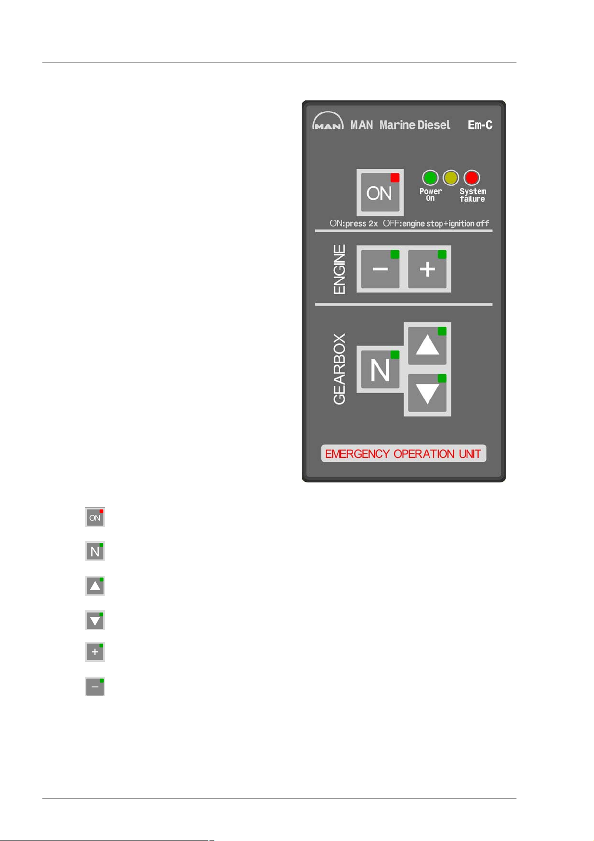
Commissioning and operation
7. Emergency operation unit::
The emergency operation control system - Em - is
conceived as a simple engine speed and gearbox
control system which enables safe continuation of
a trip in the event of a failure in the electrical con
trol lever system.
The operation unit for emergency running control is
preferably integrated next to the throttle lever in
the bridge console. For safe marine operation, the
front buttons must be easily accessible. When the
ignition is on, emergency running can be activated
by way of appropriate function buttons. A green
LED indicates operational readiness.
Operation is effected by way of six front buttons,
which light up when a requested status is achieved
and thus indicate the relevant operating or actual
status.
Key Activate emergency operation
Key Shift gearbox to neutral position
Key Shift gearbox to forwards position
Key Shift gearbox to reverse position
Key Increase engine speed
Key Decrease engine speed
LED Power On indicates the presence of supply voltage when the ignition is on
LED System Failure indicates failure status by flashing or with continuous light
92
Page 93
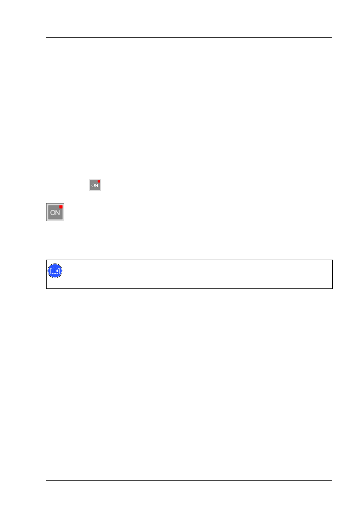
Commissioning and operation
Operating the emergency operation unit
Requirements for operation / activation / deactivation:
D The emergency running control system should be only activated while the engine is running.
Otherwise the “System Failure" LED flashes to indicate there is no engine speed signal
D The engine should be shut down via the ignition lock
When the emergency stop button is pressed, the “System Failure" LED on the Em-C operation unit lights
up when the ignition is simultaneously on as the active systems EDC engine control and emergency run
ning unit are shut down by the emergency stop.
The “System Failure" LED goes out after the emergency stop button has been released.
Operation / function of emergency operation unit in operation:
Enabling emergency operation unit
The system is ready for operation once the ignition has been turned on. This is indicated by the green
“Power-On" The red LED (Failure) must not light up. The emergency running system can now be activated
by pressing the button twice:
Pressing the button for the first time requests emergency running mode. The button flashes cycli
cally for approx. 6 seconds and an acoustic signal is issued. During this time, the request must be
acknowledged by pressing the button for a second time. The button lights up permanently once
the changeover to emergency running mode has taken place.
If there is no acknowledgement by pressing the button for a second time, the system returns to
the initial setting (operational readiness).
Note:
Once the emergency running system has been activated, it is only possible to switch back to nor
mal throttle lever mode by shutting down the engine (ignition “OFF" for at least 3 seconds)!
93
Page 94

Commissioning and operation
Gearbox control
When emergency running mode is active, the gearbox is engaged in the neutral, forwards or astern posi
tions by means of 3 button functions:
Key Shift gearbox to neutral position
Key Shift gearbox to forwards position
Key Shift gearbox to reverse position
Gearbox reversal will only take place when the engine speed is in the idle range.
It is advisable always to engage the gearbox in neutral first prior to a reversal operation.
If however the operator requests a reversal e.g. from forwards directly to astern (or vice versa) and the en
gine is at a higher speed, the engine is automatically set to idle speed prior to each active reversal opera
tion.
The relevant pressed button flashes until the desired status is reached.
It goes out when another control command is given or lights up permanently to indicate that gearbox re
versal has taken place (indication of actual status).
Engine speed control
Once the gearbox is engaged in the forwards or reverse position, the current engine speed can be in
creased or reduced by means of 2 button functions:
Key Increase engine speed
Key Decrease engine speed
As long as the + or - keys are pressed (“insert button symbol"), there is a continuous change in the engine
speed.
The increase or alteration rate is 50 revolutions / seconds.
Each individual short pressing of a button brings about a speed change of 10 engine revolutions.
The engine speed is restricted downwards to the idling speed and upwards to the maximum permitted en
gine speed.
94
Page 95

Commissioning and operation
Deactivating emergency running mode
Emergency running mode is always deactivated only after the engine has been shut down, it is necessary
for the ignition to have been turned off for at least 3 seconds.
When the ignition is turned on again, normal throttle lever mode is always activated first, i.e. the emergency
running system must be reactivated as required.
Fault messages
Two LEDs on the Em-C operation unit (green “Power On" LED and red “Failure" LED) are used to differen
tiate between various failure states:
Green LED off and red LED off
Ignition off or no supply voltage (emergency running mode not possible)
Green LED on, red LED flashes without another operator button also flashing
Drop-out of internal speed signal (function with delayed reversal times nevertheless still possible)
Green LED on, red LED flashes together with forwards button
Failure after gearbox reversal into forwards direction (this propulsion direction can no longer be activ
ated)
Green LED on, red LED flashes together with astern button
Failure after gearbox reversal into astern direction (this propulsion direction can no longer be activ
ated)
Green LED and red LED permanently on
System failure or no communication between Em-C and Em-R. (emergency operation not possible)
Em-R is the receiver component in the terminal box.
Failure states which are indicated by flashing on the Em-C operation unit must be cancelled with the key
after the fault has been rectified. The failure indications continues to flash until it is cancelled.
95
Page 96

Commissioning and operation
7.1. Override button
The Override button with LED is available as an option and is installed as an external button in the area of
the navigating consoles. A separate Override button is required for each engine.
Pressing the Override button after an alarm has reduced the engine speed recovers the original power out
put of the engine.
The Override button may be used in emergencies exclusively to protect the health and lives of the crew.
Function:
If the engine output has been reduced due to an alarm, there is the possibility to press the Override button
once (LED on) and recover the original power output of the engine. If there is another reason for power
output reduction on the engine, this does not trigger a power output reduction of the engine.
The function remains active until the Override button is pressed again (LED off) or the engine is shut
down via the ignition (off position).
Urgent recommendation:
Determine the cause of the drop in power output (alarm)!
If pressing the Override button leads to engine damage, this is not covered within the framework of MAN' li
ability for defects.
Override button
96
Page 97

Commissioning and operation
Main fuses for voltage supply + / - to the en
gine
Two main fuses with 50 A are fitted at the engine;
these trip in the event of overcurrent or short cir
cuit.
If a fuse as blown, the engine can no longer be
started.
The fuses can be reset by the operator using the
keys fitted.
Main fuse on the control unit carrier EDC
A further 3 main fuses (arrow) are installed on the
control unit carrier.
These fuses blow in the event of overcurrent or
short circuit.
The fuses can be reset by the operator using the
keys fitted.
97
Page 98

Commissioning and operation
Shutting down
Do not switch off engine immediately operation at high loads, but let it idle for about 5 minutes to achieve a
temperature equalisation.
Set the deck switch to “Neutral" and switch off the engine by means of the ignition key or Ignition button.
Remove key from starting lock.
Danger:
Ensure that the engine cannot be started by unauthorised persons.
98
Page 99

Maintenance and care
Lubrication system
Ensure utmost cleanliness when handling fuels, lubricants and coolants.
Caution:
Use only approved fuels, lubricants etc. (see brochure Fuels, lubricants etc."). Otherwise the liab
ility for defects will become null and void!
Refilling with oil
Danger:
The oil is hot-risk of scalding. Do not
touch the oil drain plug with bare fingers.
Oil is an environmental hazard.
Handle it with care!
With the engine at operating temperature, remove
the oil drain plug on the oil sump and the oil filter
bowl and allow the old oil to drain off completely.
Use a vessel of sufficient size to ensure that the oil
does not overflow.
Note:
Change the oil filter elements every time
the engine oil is changed.
Loosen oil filter cover (1) and unscrew it from the
oil module by 2-3 thread turns. The engine oil now
runs from the oil module into the oil pan.
Caution:
Allow the engine oil to run out without
residue, or otherwise engine oil can flow
from the unfiltered area into the filtered
area.
1
99
Page 100

Maintenance and care
Unscrew the oil filter cover (1) and remove it, to
gether with the oil filter insert (3).
Remove the oil filter insert (3) from the oil filter
cover. Remove the sealing ring (2) from the oil fil
ter cover.
Fit new sealing ring (2) to the filter cover (1).
Insert the new oil filter insert (3) into the oil filter
cover (1).
Insert the oil filter cover (1) in the oil module and
tighten to a torque of 40 Nm.
Changing the second oil filter insert takes place by
analogy.
1
2
3
1
2
3
100
 Loading...