

Page 1
Page 2

Page 3

Preface
This Repair Manual is designed to facilitate competent repair of the engines listed herein.
The pictures and relevant descriptions show typical work that may not always be applicable to the engine in
hand, which nevertheless does not mean that they are not correct.
In such cases the repair work is to be planned and carried out in a similar way.
Please note that all jobs described in this Repair Manual were carried out on an engine which was not installed.
The expert knowledge necessary for handling Diesel engines was taken for granted when this publication
was compiled.
Note:
Only use fuel, coolants and lubricants in accordance with MAN regulations, otherwise the manufacturer’s warranty will not apply!
For basic information on the fuels see the publication “Fuels, Lubricants and Coolants for MAN
Diesel Engines”.
You can find the approved products on the Internet at:
−http://www.man-mn.com/ " Products & Solutions " E-Business−
Any repair of components such as injection pump, alternator etc. ought to be left to our or the manufacturer’s service department.
Yours faithfully,
MAN Nutzfahrzeuge Aktiengesellschaft
Nuremberg Works
We reserve the right to make technical modifications in the course of further development.
© 2004 MAN Nutzfahrzeuge Aktiengesellschaft
Reprinting, copying or translation, even in the form of excerpts, is forbidden without the written permission
of MAN. MAN expressly reserves all rights in accordance with the law on copyright.
MTDB Technical status: 11.2004 51.99598−8157
1
Page 4
Instructions
Important instructions which concern technical safety and protection of persons are emphasised as shown
below.
Danger:
This refers to working and operating procedures which must be complied with in order to rule out
the risk to persons.
Caution:
This refers to working and operating procedures which must be complied with in order to prevent
damage to or destruction of material.
Note:
Explanations useful for understanding the working or operating procedure to be performed.
Fitting flat seals / gaskets
Flat seals / gaskets are often inserted with sealing agents or adhesives to make fitting them easier or to
achieve better sealing. Flat seals may slip in operation due to the “sewing-machine” effect, in particular if
they are used between parts with different rates of linear expansion under heat (e.g. aluminium and cast
iron), and leaks may then occur.
Example:
the cap of the front crankshaft seal. If a sealing agent or an adhesive is used here the flat seal will move
inwards in the course of time as a result of the different expansion rates of the materials. Oil will be lost, for
which the shaft seal may be thought to be responsible.
Flat seals / gaskets can be fitted properly only if the following points are observed:
D Use only genuine MAN seals/gaskets.
D The sealing faces must be undamaged and clean.
D Do not use any sealing agent or adhesive − as an aid to fitting the seals a little grease can be used if
necessary so that the seal will stick to the part to be fitted.
D Tighten bolts evenly to the specified torque.
2
Page 5

Contents
Engine type classification 5 . . . . . . . . . . . . . . . . . . . . . . . . . . . . . . . . . . . . . . . . . . . . . . . . . . . . . . . . . . . . . . . . . .
Safety instructions 6 . . . . . . . . . . . . . . . . . . . . . . . . . . . . . . . . . . . . . . . . . . . . . . . . . . . . . . . . . . . . . . . . . . . . . . . .
Troubleshooting table 12 . . . . . . . . . . . . . . . . . . . . . . . . . . . . . . . . . . . . . . . . . . . . . . . . . . . . . . . . . . . . . . . . . . . . .
General notes on engine overhaul 15 . . . . . . . . . . . . . . . . . . . . . . . . . . . . . . . . . . . . . . . . . . . . . . . . . . . . . . . . . .
Commissioning after engine overhaul 16 . . . . . . . . . . . . . . . . . . . . . . . . . . . . . . . . . . . . . . . . . . . . . . . . . . . . . . .
Engine views D 2842 LE 620 18 . . . . . . . . . . . . . . . . . . . . . . . . . . . . . . . . . . . . . . . . . . . . . . . . . . . . . . . . . . . . . . .
Engine lubrication schedule 20 . . . . . . . . . . . . . . . . . . . . . . . . . . . . . . . . . . . . . . . . . . . . . . . . . . . . . . . . . . . . . . . .
Fuel diagram 22 . . . . . . . . . . . . . . . . . . . . . . . . . . . . . . . . . . . . . . . . . . . . . . . . . . . . . . . . . . . . . . . . . . . . . . . . . . . .
Schematic diagram of cooling system 23 . . . . . . . . . . . . . . . . . . . . . . . . . . . . . . . . . . . . . . . . . . . . . . . . . . . . . . .
Fuel system
Check the base fitting of the high−pressure pump 24 . . . . . . . . . . . . . . . . . . . . . . . . . . . . . . . . . . . . . . . . . .
Removing and installing the high-pressure lines 26 . . . . . . . . . . . . . . . . . . . . . . . . . . . . . . . . . . . . . . . . . . . .
Removing and installing high-pressure pump 27 . . . . . . . . . . . . . . . . . . . . . . . . . . . . . . . . . . . . . . . . . . . . . .
Removing and installing the rail 29 . . . . . . . . . . . . . . . . . . . . . . . . . . . . . . . . . . . . . . . . . . . . . . . . . . . . . . . . . .
Removing and installing the rail pressure sensor, pressure relief valve 31 . . . . . . . . . . . . . . . . . . . . . . . .
Removing and installing the injectors 32 . . . . . . . . . . . . . . . . . . . . . . . . . . . . . . . . . . . . . . . . . . . . . . . . . . . . .
Fuel prefilter with water separator 37 . . . . . . . . . . . . . . . . . . . . . . . . . . . . . . . . . . . . . . . . . . . . . . . . . . . . . . . .
Fuel filter, exchanging filter cartridge 38 . . . . . . . . . . . . . . . . . . . . . . . . . . . . . . . . . . . . . . . . . . . . . . . . . . . . .
Flame-starter sheathed-element glow plug, removing and installing 39 . . . . . . . . . . . . . . . . . . . . . . . . . . .
Cooling system
Draining and filling coolant 40 . . . . . . . . . . . . . . . . . . . . . . . . . . . . . . . . . . . . . . . . . . . . . . . . . . . . . . . . . . . . . .
Removing and installing thermostats 41 . . . . . . . . . . . . . . . . . . . . . . . . . . . . . . . . . . . . . . . . . . . . . . . . . . . . .
Removing and installing coolant pump 42 . . . . . . . . . . . . . . . . . . . . . . . . . . . . . . . . . . . . . . . . . . . . . . . . . . . .
Repairing coolant pump with high-temperature and low-temperature parts 44 . . . . . . . . . . . . . . . . . . . . .
Cleaning cooling system 51 . . . . . . . . . . . . . . . . . . . . . . . . . . . . . . . . . . . . . . . . . . . . . . . . . . . . . . . . . . . . . . . .
Lubrication
Changing oil filter 53 . . . . . . . . . . . . . . . . . . . . . . . . . . . . . . . . . . . . . . . . . . . . . . . . . . . . . . . . . . . . . . . . . . . . . .
Removing and installing the oil cooler 54 . . . . . . . . . . . . . . . . . . . . . . . . . . . . . . . . . . . . . . . . . . . . . . . . . . . .
Removing and installing, repairing oil pump 55 . . . . . . . . . . . . . . . . . . . . . . . . . . . . . . . . . . . . . . . . . . . . . . .
Oil injection nozzle 59 . . . . . . . . . . . . . . . . . . . . . . . . . . . . . . . . . . . . . . . . . . . . . . . . . . . . . . . . . . . . . . . . . . . . .
Flywheel / Crankshaft seal
Removing and fitting vibration damper, replacing front crankshaft gasket 61 . . . . . . . . . . . . . . . . . . . . . .
Removing and installing flywheel,replacing starter gear ring 65 . . . . . . . . . . . . . . . . . . . . . . . . . . . . . . . . .
Replacing crankshaft seal (flywheel end) 67 . . . . . . . . . . . . . . . . . . . . . . . . . . . . . . . . . . . . . . . . . . . . . . . . . .
Replacing the bearing race 68 . . . . . . . . . . . . . . . . . . . . . . . . . . . . . . . . . . . . . . . . . . . . . . . . . . . . . . . . . . . . . .
Crankshaft gaskets 69 . . . . . . . . . . . . . . . . . . . . . . . . . . . . . . . . . . . . . . . . . . . . . . . . . . . . . . . . . . . . . . . . . . . .
Intake / exhaust system
Removing and installing intake manifold 70 . . . . . . . . . . . . . . . . . . . . . . . . . . . . . . . . . . . . . . . . . . . . . . . . . .
Removing and installing exhaust pipe 71 . . . . . . . . . . . . . . . . . . . . . . . . . . . . . . . . . . . . . . . . . . . . . . . . . . . .
Turbocharger, trouble shooting 72 . . . . . . . . . . . . . . . . . . . . . . . . . . . . . . . . . . . . . . . . . . . . . . . . . . . . . . . . . .
Checking the charge-air pressure 74 . . . . . . . . . . . . . . . . . . . . . . . . . . . . . . . . . . . . . . . . . . . . . . . . . . . . . . . .
Removing and installing turbocharger 75
Checking axial and radial clearance of turbocharger rotor shaft 77 . . . . . . . . . . . . . . . . . . . . . . . . . . . . . .
. . . . . . . . . . . . . . . . . . . . . . . . . . . . . . . . . . . . . . . . . . . . . . . . . . . .
Cylinder head
Removing and installing the cylinder head 78 . . . . . . . . . . . . . . . . . . . . . . . . . . . . . . . . . . . . . . . . . . . . . . . . .
Setting the valve clearance 82 . . . . . . . . . . . . . . . . . . . . . . . . . . . . . . . . . . . . . . . . . . . . . . . . . . . . . . . . . . . . .
Dismantling and assembling the rocker arm mechanism 83 . . . . . . . . . . . . . . . . . . . . . . . . . . . . . . . . . . . .
Removing and installing valves 87 . . . . . . . . . . . . . . . . . . . . . . . . . . . . . . . . . . . . . . . . . . . . . . . . . . . . . . . . . .
Removing and installing valve guides 93 . . . . . . . . . . . . . . . . . . . . . . . . . . . . . . . . . . . . . . . . . . . . . . . . . . . . .
Replacing valve seat insert 94 . . . . . . . . . . . . . . . . . . . . . . . . . . . . . . . . . . . . . . . . . . . . . . . . . . . . . . . . . . . . .
Reworking valve seat 96 . . . . . . . . . . . . . . . . . . . . . . . . . . . . . . . . . . . . . . . . . . . . . . . . . . . . . . . . . . . . . . . . . .
Refacing valves 99 . . . . . . . . . . . . . . . . . . . . . . . . . . . . . . . . . . . . . . . . . . . . . . . . . . . . . . . . . . . . . . . . . . . . . . .
3
Page 6

Contents
Valve timing
Removing and installing the gear case 100 . . . . . . . . . . . . . . . . . . . . . . . . . . . . . . . . . . . . . . . . . . . . . . . . . . . .
Removing and installing camshaft 102 . . . . . . . . . . . . . . . . . . . . . . . . . . . . . . . . . . . . . . . . . . . . . . . . . . . . . . . .
Removing and fitting camshaft bearing bushes 105 . . . . . . . . . . . . . . . . . . . . . . . . . . . . . . . . . . . . . . . . . . . .
Checking the valve timing 114 . . . . . . . . . . . . . . . . . . . . . . . . . . . . . . . . . . . . . . . . . . . . . . . . . . . . . . . . . . . . . . .
Crankgear, pistons
Removing and installing crankshaft 115 . . . . . . . . . . . . . . . . . . . . . . . . . . . . . . . . . . . . . . . . . . . . . . . . . . . . . .
Removing and installing pistons with conrods 118 . . . . . . . . . . . . . . . . . . . . . . . . . . . . . . . . . . . . . . . . . . . . . .
Removing pistons from conrod and fitting, checking − replacing conrod 121 . . . . . . . . . . . . . . . . . . . . . . .
Removing and installing piston rings 123 . . . . . . . . . . . . . . . . . . . . . . . . . . . . . . . . . . . . . . . . . . . . . . . . . . . . .
Replacing cylinder liners 125 . . . . . . . . . . . . . . . . . . . . . . . . . . . . . . . . . . . . . . . . . . . . . . . . . . . . . . . . . . . . . . . .
Measuring piston protrusion 129 . . . . . . . . . . . . . . . . . . . . . . . . . . . . . . . . . . . . . . . . . . . . . . . . . . . . . . . . . . . . .
Attachments
Removing and installing starter motor 130 . . . . . . . . . . . . . . . . . . . . . . . . . . . . . . . . . . . . . . . . . . . . . . . . . . . .
V−belts 131 . . . . . . . . . . . . . . . . . . . . . . . . . . . . . . . . . . . . . . . . . . . . . . . . . . . . . . . . . . . . . . . . . . . . . . . . . . . . . . .
Tensioning and changing V−belt 132 . . . . . . . . . . . . . . . . . . . . . . . . . . . . . . . . . . . . . . . . . . . . . . . . . . . . . . . . .
Removing and installing speed pickup 133 . . . . . . . . . . . . . . . . . . . . . . . . . . . . . . . . . . . . . . . . . . . . . . . . . . . .
Service Data
Specifications 136 . . . . . . . . . . . . . . . . . . . . . . . . . . . . . . . . . . . . . . . . . . . . . . . . . . . . . . . . . . . . . . . . . . . . . . . . .
Crankcase 137 . . . . . . . . . . . . . . . . . . . . . . . . . . . . . . . . . . . . . . . . . . . . . . . . . . . . . . . . . . . . . . . . . . . . . . . . . . . .
Cylinder liner 137 . . . . . . . . . . . . . . . . . . . . . . . . . . . . . . . . . . . . . . . . . . . . . . . . . . . . . . . . . . . . . . . . . . . . . . . . . .
Crankshaft 138 . . . . . . . . . . . . . . . . . . . . . . . . . . . . . . . . . . . . . . . . . . . . . . . . . . . . . . . . . . . . . . . . . . . . . . . . . . . .
Flywheel and starter gear ring 141 . . . . . . . . . . . . . . . . . . . . . . . . . . . . . . . . . . . . . . . . . . . . . . . . . . . . . . . . . . .
Conrods 142 . . . . . . . . . . . . . . . . . . . . . . . . . . . . . . . . . . . . . . . . . . . . . . . . . . . . . . . . . . . . . . . . . . . . . . . . . . . . . .
Pistons 143 . . . . . . . . . . . . . . . . . . . . . . . . . . . . . . . . . . . . . . . . . . . . . . . . . . . . . . . . . . . . . . . . . . . . . . . . . . . . . . .
Cylinder head 144 . . . . . . . . . . . . . . . . . . . . . . . . . . . . . . . . . . . . . . . . . . . . . . . . . . . . . . . . . . . . . . . . . . . . . . . . .
Valve gear 146 . . . . . . . . . . . . . . . . . . . . . . . . . . . . . . . . . . . . . . . . . . . . . . . . . . . . . . . . . . . . . . . . . . . . . . . . . . . .
Engine lubrication D 2842 LE 620 149 . . . . . . . . . . . . . . . . . . . . . . . . . . . . . . . . . . . . . . . . . . . . . . . . . . . . . . . .
Cooling system 151 . . . . . . . . . . . . . . . . . . . . . . . . . . . . . . . . . . . . . . . . . . . . . . . . . . . . . . . . . . . . . . . . . . . . . . . .
Repairing coolant pump with high−temperatureand low−temperature parts 151 . . . . . . . . . . . . . . . . . . . .
Turbocharger 152 . . . . . . . . . . . . . . . . . . . . . . . . . . . . . . . . . . . . . . . . . . . . . . . . . . . . . . . . . . . . . . . . . . . . . . . . .
Fuel system 153 . . . . . . . . . . . . . . . . . . . . . . . . . . . . . . . . . . . . . . . . . . . . . . . . . . . . . . . . . . . . . . . . . . . . . . . . . .
Starter motor 154 . . . . . . . . . . . . . . . . . . . . . . . . . . . . . . . . . . . . . . . . . . . . . . . . . . . . . . . . . . . . . . . . . . . . . . . . . .
Torque guide values 155 . . . . . . . . . . . . . . . . . . . . . . . . . . . . . . . . . . . . . . . . . . . . . . . . . . . . . . . . . . . . . . . . . . .
Special tools 161 . . . . . . . . . . . . . . . . . . . . . . . . . . . . . . . . . . . . . . . . . . . . . . . . . . . . . . . . . . . . . . . . . . . . . . . . . . . .
Index 174 . . . . . . . . . . . . . . . . . . . . . . . . . . . . . . . . . . . . . . . . . . . . . . . . . . . . . . . . . . . . . . . . . . . . . . . . . . . . . . . . . . .
4
Page 7

All the engines dealt with here are related in terms of their design and make up a family.
The type classification, which is made up of a series of letters and numbers, reveals some of the features
of the engine in question provided the reader is familiar with the underlying nomenclature.
The system is explained below using the model type D 2842 LE 620 as an example:
D The “D” at the start of the type classification stands for “Diesel”
28 The numbers “28” indicates that the power plant in question has a bore of 128 mm
4 The “4” means 142 mm stroke
2 The “2” indicates that there are 12 cylinders. If there is a “0”, this is a 10−cylinder engine
L This letter stands for “charge−air cooling” (German: Ladeluftkühlung)
E The “E” stands for “fitted engine” (German: Einbaumotor) and is intended to distinguish MAN
vehicle engines
620 This is a factory-internal development number
5
Page 8
Safety instructions
General information
This brief overview summarises important instructions and is structured into areas of main concern in order
to impart the knowledge necessary to prevent accidents involving injury to persons, damage to the engine
or other property and harm to the environment. Additional notes are included in the operator’s manual for
the engine.
Important:
If despite all safety precautions an accident occurs as a result of contact with caustic acids, penetration of
fuel into the skin, scalding with hot oil, anti-freeze splashes into the eyes etc, consult a doctor immedi-
atel.
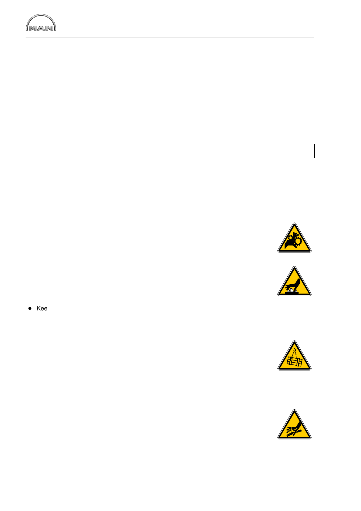
1. Instructions for preventing accidents with injury to persons
Checks, setting jobs and repair work must be carried out by authorised skilled personnel only.
D When carrying out maintenance and repair work, ensure that the engine cannot be
accidentally started from the bridge by unauthorised persons.
D The engine must be started and operated by authorised personnel only.
D When the engine is running, do not get too close to revolving components.
Wear tight-fitting working clothes.
D Do not touch hot engine with bare hands: risk of burning yourself.
D Keep engine vicinity, ladder and steps free of oil and grease. Accidents resulting from
slipping may have serious consequences.
D Work only with tools that are in good condition. Worn spanners slip: risk of injuries.
D Persons must not stand under an engine suspended from a crane hook.
Keep lifting gear in good order.
D Open coolant circuit only after the engine has cooled down. If opening the coolant
circuit while the engine is hot is unavoidable, observe the instructions in the chapter
“Maintenance and care” in the Operator’s Manual.
D Neither retighten nor open pressurised pipelines and hoses (lube oil circuit, coolant
circuit and downstream hydraulic oil circuit if fitted): risk of injuries resulting from
emerging fluids.
D When checking the injection nozzles, do not hold your hands in the fuel jet.
Do not inhale fuel mist.
6
Page 9
Safety instructions
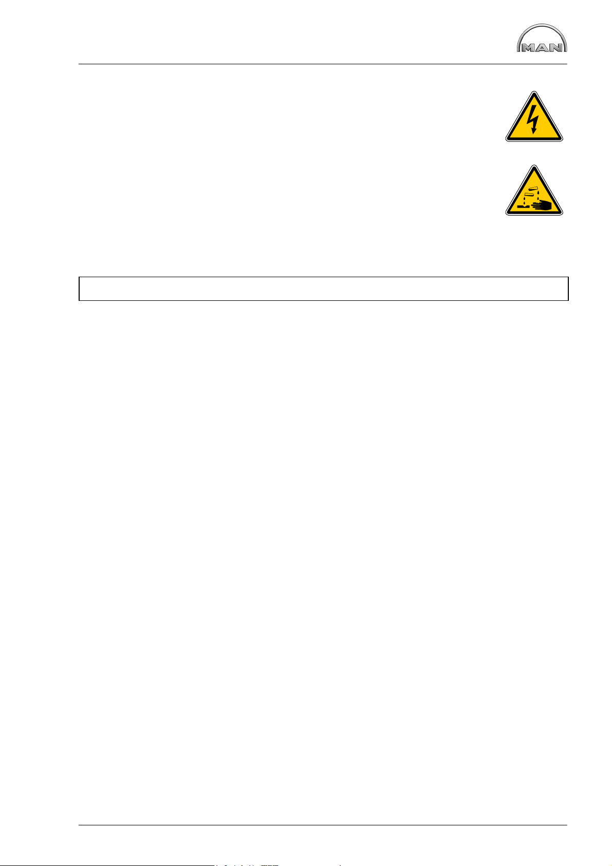
D When working on the electrical system, unplug earth cable from battery first and
reconnect it last to avoid short-circuits.
D Observe the manufacturer’s instructions for handling batteries.
Caution:
Battery acid is toxic and caustic. Battery gases are explosive.
D When carrying out welding work, observe the “Information sheets for welders”.
2. Instructions for preventing damage to the engine and premature wear
D Prior to repairing the engine, clean it thoroughly. Ensure that dirt, sand or foreign matter will
not get into the engine during repair work.
D In the event of operational faults immediately identy the cause and rectify to prevent more serious
damage.
D Always use genuine MAN parts only. Installation of “equally” good parts from other suppliers may cause
severe damage for which the workshop carrying out the work is responsible.
D Never operate the engine while it is dry, i.e. without lubricant or coolant.
Use a suitable label to mark engines not ready for operation.
D Only use operating materials (fuel, engine oil, antifreeze and anticorrosion agents) approved by MAN.
Ensure that everything is kept clean. Diesel fuel must be free of water.
D Do not fill up with engine oil above the max. notch on the dipstick. Do not exceed the engine’s
maximum permissible operating inclination.
Non-compliance with these instructions may cause severe engine damage.
D Control and monitoring devices (charge check, oil pressure, coolant temperature) must work faultlessly.
D Observe the instructions for operating the alternator; see chapter “Maintenance and care” in the
Operator’s Manual.
7
Page 10
Safety instructions
3. Instructions for preventing environmental damage
Engine oil and filter cartridges and elements, fuel / fuel filters
D Take old oil to an old oil disposal point only.
D Ensure without fail that oil and Diesel fuel will not get into the sewerage system or the ground.
Caution:
Danger of contaminating potable water!
D Treat filter elements and cartridges as special waste.
Coolant
D Treat undiluted anticorrosion and / or antifreeze agents as special waste.
D The regulations of the relevant local authorities are to be observed for the disposal of spent coolants.
4. Instructions for handling used engine oil *
Prolonged or repeated contact of any kind of engine oil with the skin causes the skin to degrease, which
may result in dryness, irritation or inflammation. Old engine oil also contains hazardous substances which
in animal experiments have caused skin cancer. Handling old engine oil does not pose any health hazard if
the basic safety and hygiene related regulations are observed.
Health and safety regulations:
D Avoid prolonged, excessive or repeated contact of old engine oil with the skin.
D Use a suitable skin protection agent or wear protective gloves.
D Clean the skin that has been in contact with engine oil.
− Wash yourself thoroughly with soap and water. A nailbrush is an effective aid.
− Special hand cleaning agents facilitate cleaning soiled hands.
− Do not use petrol, Diesel fuel, gas oil, fluxes or solvents as cleaning agents.
D After washing apply moisturising handcream to your skin.
D Change oil-soaked clothes and shoes.
D Do not put any oil-soaked cloths into pockets.
Pay meticulous attention to the proper disposal of old engine oil.
− Old oil is a water hazard −
Therefore, do not pour any old oil into the ground, the drains or the sewerage system. Any violation of this
rule is punishable.
Collect and dispose of old engine oil properly. For information concerning collection points, contact seller,
supplier or the local authorities.
∗ Based on the “Information sheed for handling used engine oil”
(Notes on how to handle old engine oil).
8
Page 11
Safety regulations
5. Special instructions when working on the common rail system
Accident protection
D Risk of injury!
Fuel jets can cut through skin.
The atomisation of fuel creates a fire risk.
− When the engine is running never loosen the screw connections on the fuel’s high-
pressure side of the common rail system (injection line from the high-pressure pump
to the rail, on the rail and on the cylinder head to the injector)
− Keep away from the engine when it is running
D Risk of injury!
When the engine is running the lines are constantly under a fuel pressure of up
to 1600 bar.
− Wait at least a minute until the pressure in the rail has dropped before loosening a
screw connection
− If necessary check the pressure drop in the rail with MAN-Cats
D Risk of injury!
− People with pacemaker must keep at least 20 cm away from the running engine
− Do not touch live parts on the electric connection of the injectors when the engine is
running
9
Page 12

Safety regulations
Cleanliness
Today modern components of diesel injection consist of high-precision parts which are exposed to extreme
stresses. The high-precision technology requires the utmost cleanliness during all work on the fuel system.
Even a particle of dirt over 0.2 mm can lead to the failure of components.
The measures described as follows are therefore essential before work begins:
Risk of damage from penetration of dirt!
D Before working on the clean side of the fuel system clean the engine and the engine
compartment (high-pressure cleaner). During cleaning the fuel system must be closed
D Carry out visual inspection for any leakage or damage to the fuel system
D Do not spray the high-pressure cleaner direct onto the electric components, or alternati-
vely keep them covered
D Do not carry out any welding or sanding work in the engine compartment during mainte-
nance / repair
D Avoid air movements (any swirling of dust when starting engines)
D The area of the still closed fuel system must be cleaned and dried with the aid of com-
pressed air
D Remove detached particles of dirt such as paint chippings and insulation material with a
suitable extractor (industrial type vacuum cleaner)
D Cover areas of the engine compartment from which dust particles could be detached
with clean foil
D Wash your hands and put on clean work clothes before starting the disassembly work
D Clean tools and working materials before starting to work
10
Page 13

Safety regulations
When carrying out the work it is essential to comply with the following measures:
Risk of damage from penetration of dirt!
D When the clean side of the fuel system has been opened it is not permissible to use
compressed air for cleaning
D During assembly work loose dirt must be removed with the aid of suitable extractors
(industrial type vacuum cleaners)
D Use only fluff-free cleaning cloths on the fuel system
D Only tools without any damage may be used (cracked chrome coatings)
D When removing and installing components do not use materials such as cloths, cardbo-
ard or wood since these could shed particles and fine fibres
D If any paint chips / flakes off when connections are loosened (from possible over-coa-
ting) these chippings must be carefully removed before finally loosening the screw connection
D The connection openings of all removed parts on the clean side of the fuel system are
to be closed immediately with suitable caps (see special tools, page 172)
D These caps / stoppers must be packed protected from dust prior to use and after being
used once they must be disposed of
D Following this all the components must be carefully stored in a clean, closed container
D Never use used cleaning or testing liquids for these components
D New parts must not be removed from their original packing material until directly before
use
D Work on removed components may be carried out only at a workplace specially equip-
ped for it
D If removed parts are shipped always use the original packing material of the new part
11
Page 14

Troubleshooting table
Faults and possible causes
We recommend
Repair work is to be considered complete only after the damage which has occurred and the possible
causes have been eliminated. Ascertaining the causes of damage is frequently more difficult than eliminating the damage caused. For this reason we recommend you have the operational fault exactly described to
you before removal or disassembly work is commenced. Then, track down the probable causes by asking
specific questions, examining and eliminating these causes one by one with the aid of the table and your
own experience. This helps to reduce repairs to those necessary and counter complaints about “premature” exchange of parts and expensive working and downtimes.
Remark:
The subsequent list is meant to be a memory aid so that no causes of damage will be overlooked in the
elimination of faults. The precondition for this, however, is that you are familiar with the Repair Manual for
the engine and the relevant Operator’s Manual as well as the publication “Fuels, Lubricants, Coolants for
MAN Diesel Engines”.
12
Page 15

Fault table
1. EDC self-diagnosis
2. Starter motor turns over engine slowly or not at all
3. Starter motor turns, engine fails to start, engine fails to start / difficult to start when cold
4. Engine stalls (dies) during operation, no longer starts (starter motor turns),
engine fails to start / difficult to start when hot
5. Sudden, temporary engine shutdown, engine does not reach full revs
6. Engine runs at idle speed only, no throttle response
7. Engine runs at increased idle speed only, no throttle response
8. Rated engine speed significantly reduced (even at no load)
9. Reduced power output in all ranges
10. Irregular engine operation, loss of traction
11. Unstable idle speed, engine surges, misfiring, engine knocking
12. Engine judder
13. Unusual combustion noises
14. Excessive smoke emission: white smoke / blue smoke
15. Excessive smoke emission: black smoke
16. Engine temperature too high (coolant loss)
17. Fuel consumption too high
18. Lubrication oil pressure too low
19. Lube oil pressure too high
20. Lube oil consumption too high
21. Engine too “loud” / mechanical noises
22. Idle speed cannot be adjusted with idle speed operating unit
Possible causes
x x Battery flat, battery lead connections loose or corroded, break in power circuit
x Crankshaft drive blocked
x x Starter solenoid switch sticks (clicks) / damaged, cable connection loose or dam-
x x Starter motor / starter interlock relay defective (carbon brushes worked loose /
x x x x Engine oil viscosity unsuitable, not suitable for ambient temperature, lube oil qual-
x x Oil level in oil pan too high
x Oil level in pan too low, oil in oil pan too thin (mixed with condensate or fuel)
x Engine temperature too high
x Oil filter clogged
x x Oil pressure gauge defective
x Safety valve in the oil circuit defective (does not close, spring fatigued or broken)
x x Heavy bearing wear
x Oil pump gears heavily worn
x x x Engine cold
x Lube oil entering combustion chamber (piston rings worn, piston rings broken) −
x Safety valve in oil circuit defective (does not open), oil lines / oil galleries clogged
x x Piston rings heavily worn, broken
x x Piston pins or crankshaft bearings loose
x x x Valve clearance not correct
x x Valves jammed
x x x x Compression deficient, or more than 3−4 bar pressure difference between individ-
x x x Valve seats leaking
o x x Increased power input due to defective secondary loads / consumers such as
x x x x x Air filter fouled or clogged, charge air system leaking, air intake / exhaust lines
x x x x x x x x x Fuel low pressure system: fuel tank, prefilter, water trap faulty / clogged / mould /
x x x x x x x x Fuel low pressure system: fuel lines leaking, broken, clogged
aged
worn, winding damaged, short to ground)
ity does not comply with specifications
x Timing gears worn, tooth flank backlash too great
valve stem guide worn − overpressure in crankcase (crankcase breather
clogged)
x Leaks in lube oil circuit, particularly at turbocharger and oil cooler
x Valve stems heavily worn, bent
ual cylinders
hydraulic pumps, fan etc., power take-off engaged
clogged / leaking
fungal attack, fuel unsuitable / contaminated (paraffin added)
13
Page 16

Fault table
1. EDC self-diagnosis
2. Starter motor turns over engine slowly or not at all
3. Starter motor turns, engine fails to start, engine fails to start / difficult to start when cold
4. Engine stalls (dies) during operation, no longer starts (starter motor turns),
engine fails to start / difficult to start when hot
5. Sudden, temporary engine shutdown, engine does not reach full revs
6. Engine runs at idle speed only, no throttle response
7. Engine runs at increased idle speed only, no throttle response
8. Rated engine speed significantly reduced (even at no load)
9. Reduced power output in all ranges
10. Irregular engine operation, loss of traction
11. Unstable idle speed, engine surges, misfiring, engine knocking
12. Engine judder
13. Unusual combustion noises
14. Excessive smoke emission: white smoke / blue smoke
15. Excessive smoke emission: black smoke
16. Engine temperature too high (coolant loss)
17. Fuel consumption too high
18. Lubrication oil pressure too low
19. Lube oil pressure too high
20. Lube oil consumption too high
21. Engine too “loud” / mechanical noises
22. Idle speed cannot be adjusted with idle speed operating unit
Possible causes
x x x x x x x Fuel low pressure system: air in system (turn on ignition when bleeding system)
x x x x x x x x x Fuel low pressure system: feed pump, main filter
x x x x x o x x Fuel high pressure system: injectors defective / clogged / leaking / coked
x x x x o Fuel high pressure system: pressure lines − constriction, cavitation, leaking
x x o x x x x o Fuel high pressure system: high-pressure pump worn
x x x x x o Pedal value sensor (driving lever signal) defective: connection lines, short circuit,
x x EDC rpm sensor defective, lead defective
x x o EDC rpm sensor, polarity reversed
x x x x o o o o EDC detects incorrect engine speed (interference signal on rpm sensor lead)
x x x EDC boost pressure sensor: faulty, incorrect, implausible with atmospheric pres-
x x o x Exhaust turbocharger leaking or defective
x Intercooler leaking, defective
x o x x o x EDC coolant temperature sensor: faulty, line fault
x x x EDC charge-air temperature sensor: faulty, line fault
o x x Radiator fouled or failure of cooling system (temperatures too high)
x Coolant level too low, air in the coolant circuit
x V-belt for coolant pump drive not tensioned correctly
x x Incorrect V-belt tension
x Coolant pump leaking, defective / thermostat defective, does not open
x Coolant lines leaking, blocked or twisted
x Coolant entering combustion chamber (cylinder head / gasket leaking)
x x x o o Power supply to EDC control unit interrupted or battery voltage too low
x o o o EDC control unit defective (internal fault)
x Incorrect EDC control unit (check MAN part number)
x Afterrunning not completed
x x Thermostat defective
x Engine bearings worn
interruption
sure sensor, line fault
x Turbine and compressor wheel in the turbocharger soiled (running off balance)
14
Page 17

General notes on engine overhaul
The service life of an engine is influenced by very different factors. It is therefore not possible to specify
certain fixed numbers of operating hours for general overhauls.
In our view, it is not necessary to open up and engine or perform a general overhaul
as long as the engine has good compression values and the following operating values have not changed
significantly in relation to the values measured on commissioning the engine:
D Charging pressure
D Exhaust temperature
D Coolant and lubricant temperature
D Oil pressure and oil consumption
D Smoke emissions
The following criteria greatly influence the length of the engine service life:
D Correct power output setting according to the type of application
D Technically correct installation
D Inspection if installation by authorised personnel
D Regular maintenance as per maintenance plan
D Choice and quality of lube oil, fuel and coolant in accordance with the publication
“Fuels, Lubricants and Coolants for MAN Diesel Engines”
15
Page 18
Commissioning after engine overhaul
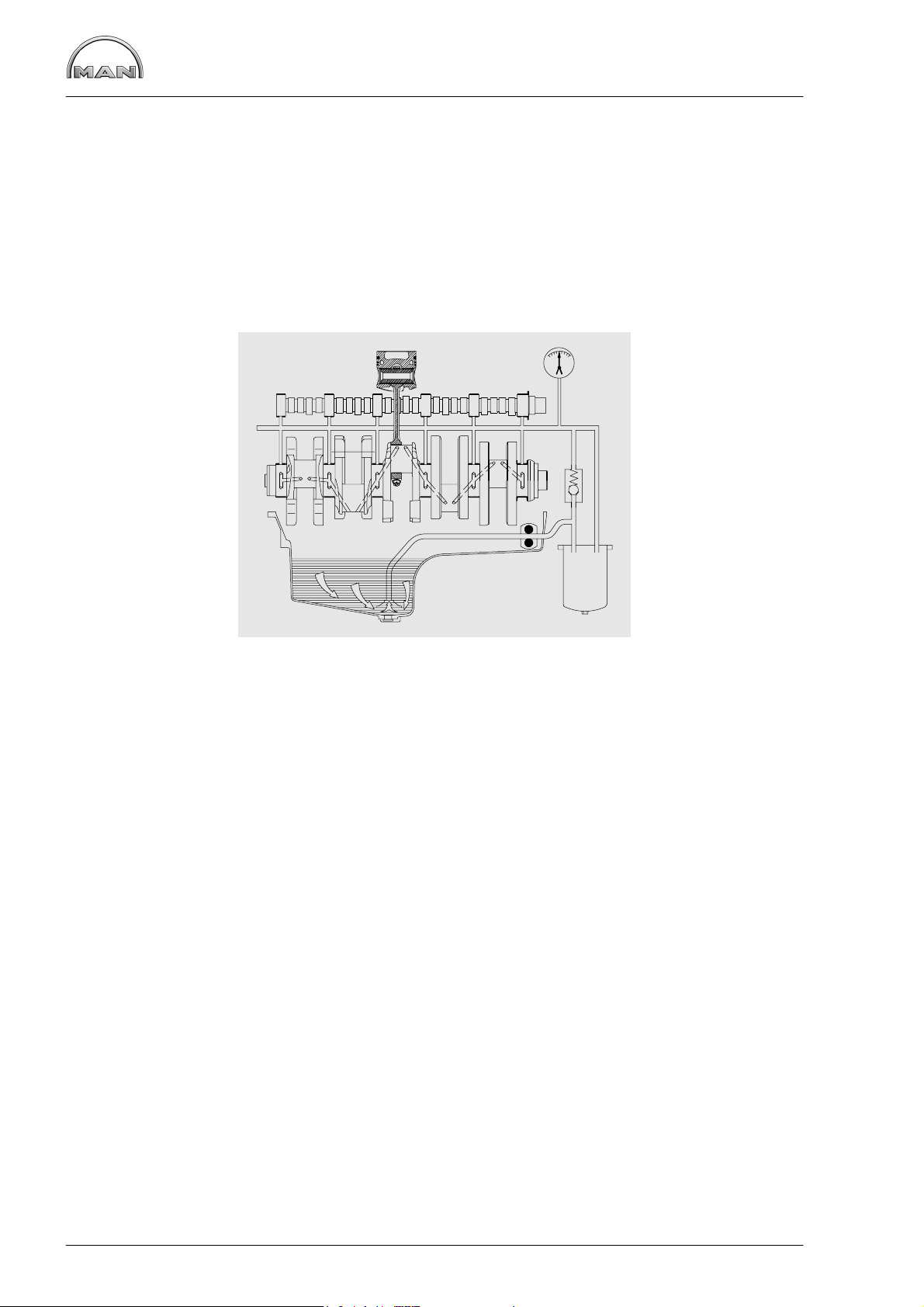
Pressurisation
It is extremely important for internal combustion engines (following the completion of repair work, i.e. in
their dry state) to be pressurised with lube oil before being recommissioned. This procedure can also be
used for ascertaining damage and its causes.
If engines are not pressurised, the risk of premature damage to bearing surfaces is very high because it
takes a relatively long period of time for the lube oil drawn in from the oil pan via the oil pump to reach the
individual bearings.
Such incipient damage need not necessarily lead to immediate bearing failure, but may impair the proper
functioning of the bearings and reduce their service lives.
Diagram of the oil flow with unpressurised engines
16
Page 19
Commissioning after engine overhaul
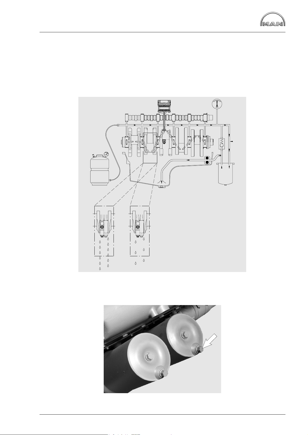
Pressurising an engine affords the following advantages:
D All engine parts are lubricated before engine startup; a lubricating film can be built up inside the bear-
ings as early as after the first few rotations of the crankshaft, thereby preventing damage to the bearing
races
D Any loss of oil, be it the result of excessively large bearing play or leaks from the crankcase or from
crankcase bores which may not be plugged, can be detected immediately. For this purpose, mount the
engine on an assembly dolly, remove the oil pan and install a suitable oil collector under the crankcase
in such a way that the bearings are visible
Performance of pressurisation:
At least 30% of the total oil quantity is forced from the pressurisation container into the engine oil circuit.
The operating pressure serves as the yardstick for the pressure to be forced in and must not be exceeded.
The pressurisation container is connected up to the engine oil circuit at the oil filter (screw plug).
17
Page 20
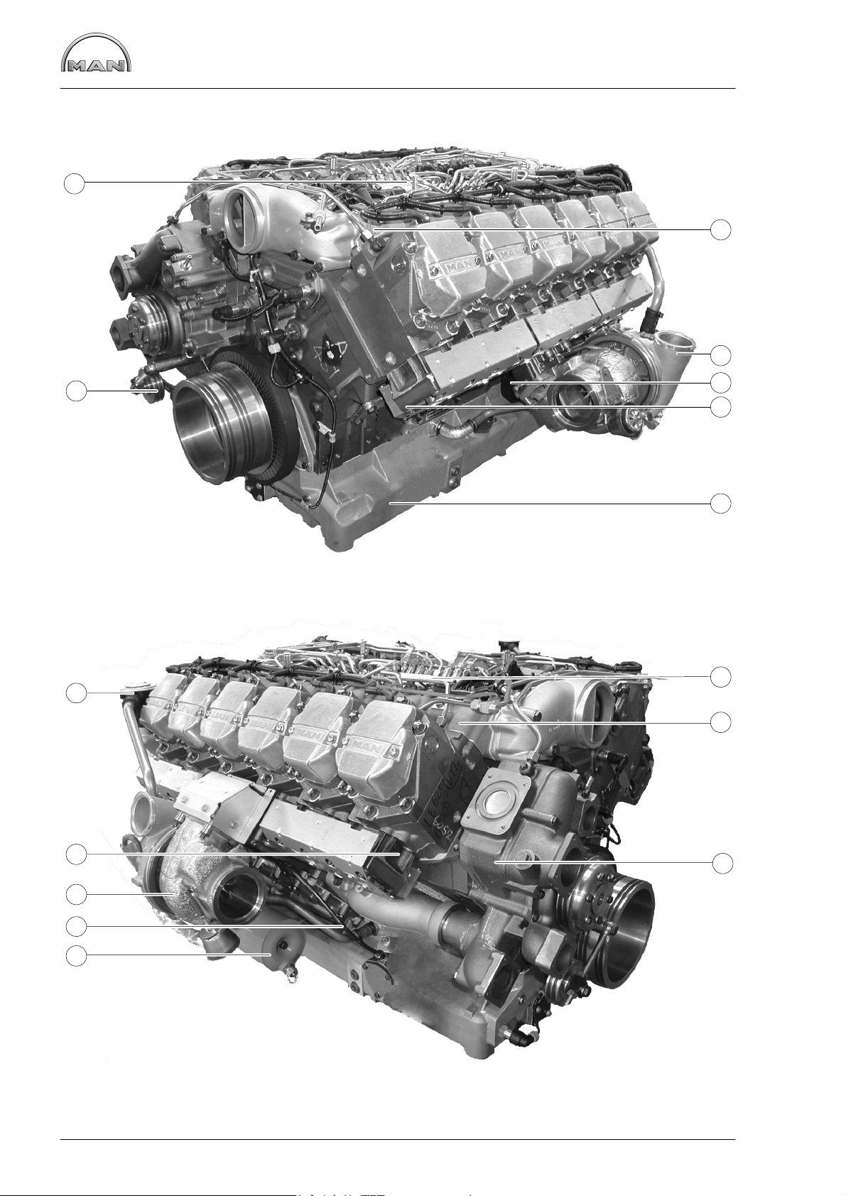
Engine views D 2842 LE 620
7
1
2
6
11
3
4
5
7
1
4
2
10
9
8
18
Page 21

À In take pipe
Á Turbocharger
 Starter motor
à Exhaust manifold
Ä Oil sump
Å Tension pulley
Æ Rail
Ç Coolant pump
È Oil filter
É Oil dipstick
Engine views D 2842 LE 620
11
Oil separator valve for crankcase breather
19
Page 22
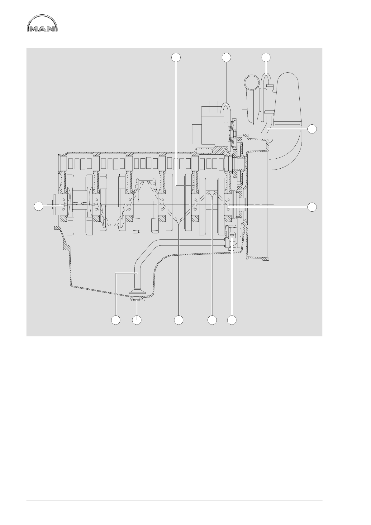
Engine lubrication schedule
1 2 3
4
5
À Oil line to crankshaft
Á High−pressure pump lubrication
 Lubricating oil lines to exhaust turbochargers
à Oil return line from exhaust turbochargers
5
67789
Å Oil pump with oil pressure relief valves
Æ Holes for conrod bearing lubrication
Ç Oil drain screw
È Oil intake pipe
Ä Holes for main bearing lubrication
20
Page 23
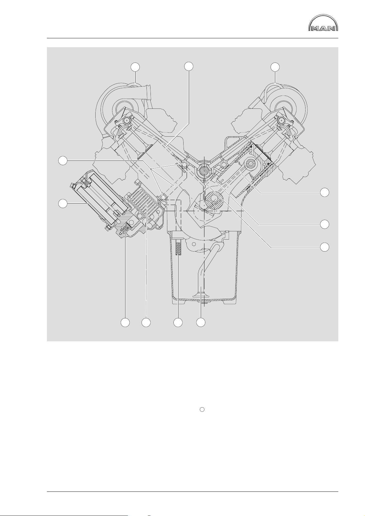
Engine lubrication schedule
11
10
1 1
2
3
4
8
À Lubricating oil lines to exhaust turbochargers
Á Rocker arm lubrication
 Piston pin lubrication
à Spray nozzles for piston cooling and
cam lubrication
Ä Camshaft bearing lubrication
5
79
6
Å Oil intake pipe
Æ Oil pressure relief valves
Ç Oil cooler
È Bypass valve
É Oil filter
11
Main oil galleries
21
Page 24
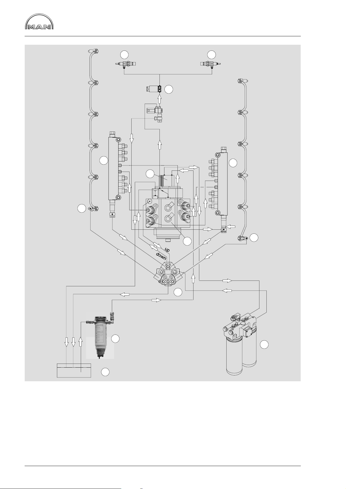
Fuel diagram
9
1010
4
4
6
3
3
14
2
5
3
8
2
1
À Tank
Á Fuel prefilter with water separator
 Injector
à Rail
Ä High pressure pump
7
Å Fuel pump
Æ Fuel filter
Ç Fuel distributor
È Solenoid valve
É Glow plug
22
Page 25
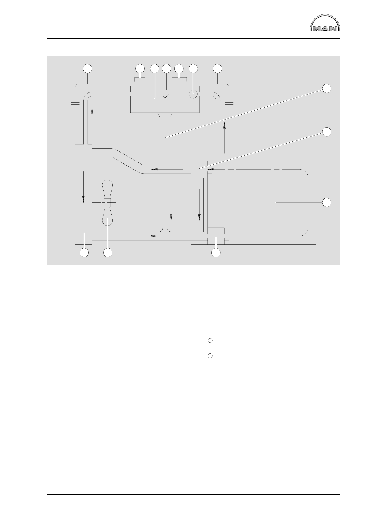
Schematic diagram of cooling system
1 12 3 4 5
6
7
8
9
12
À Overflow and vent pipe Æ Filler pipe
Á Positive pressure / negative pressure valve Ç Thermostat
 Coolant level in surge tank È Engine / crankcase
à Surge tank É Water pump
Ä Coolant filler neck
Å Degassing system
1011
11
Fan
12
Radiator / intercooler
23
Page 26
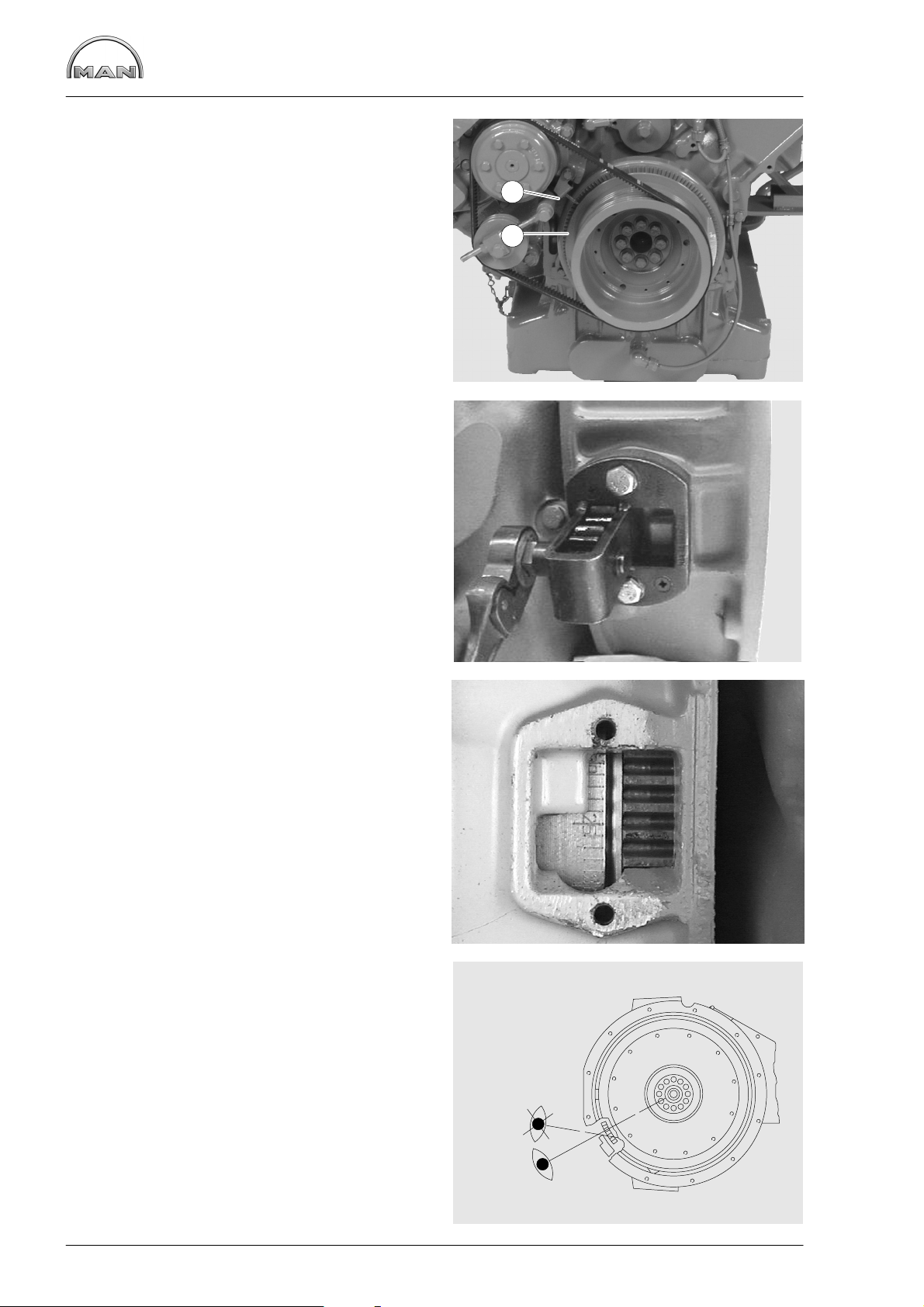
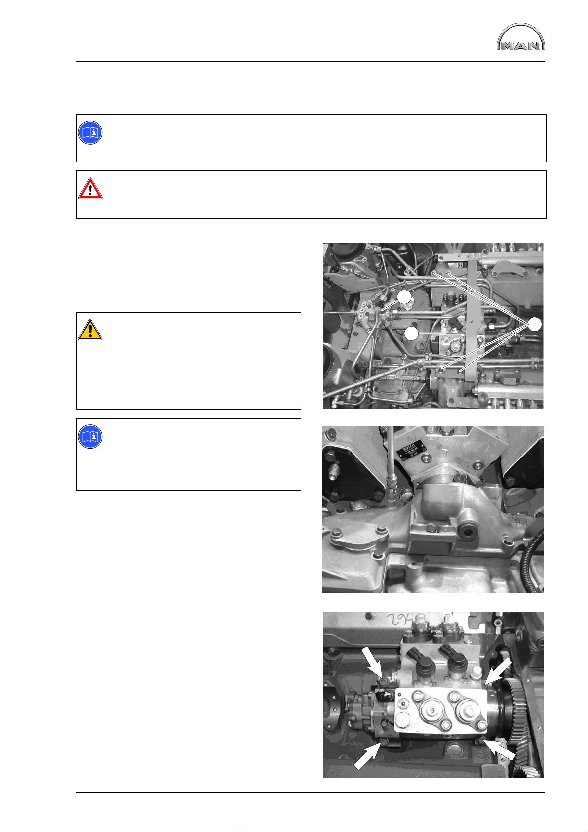
Check the base fitting of the high−pressure pump
Check the base fitting of the high−
pressure pump
Fig. 1 and Fig. 2
For the purpose of checking the start−of−delivery
setting, an “OT” (= TDC) mark and a scale from
10...50° before TDC are engraved on a disc Á
fitted in front of the torsional vibration damper.
The scale marks are read against an indicator À
fitted to the crankcase.
To turn the engine over manually during the setting
work, a plate with a central hexagon bolt must be
located on the front side of the crankshaft pulley.
For this purpose, the speed pickup together with
the plate is to be previously detached.
1
2
1
Fig. 3
The graduated scale on the flywheel, which is visible through the inspection hole in the flywheel
housing, is often difficult to access. However it
must be used to readjust the indicator after the
vibration damper has been removed or replaced.
For this purpose, before the vibration damper with
scale disc is installed, the engine must be set to
“TDC” using the flywheel marking.
The indicator must then be aligned so that its
measuring edge points exactly to the “TDC” mark
on the scale disc.
Fig. 4
To avoid read−off errors, always look over the
notch on the flywheel housing vertically to the
centre of the flywheel.
The marking on the graduated scale must be on
the imaginary “notch − flywheel centre” line.
2
3
24
4
Page 27
Check the base fitting of the high−pressure pump
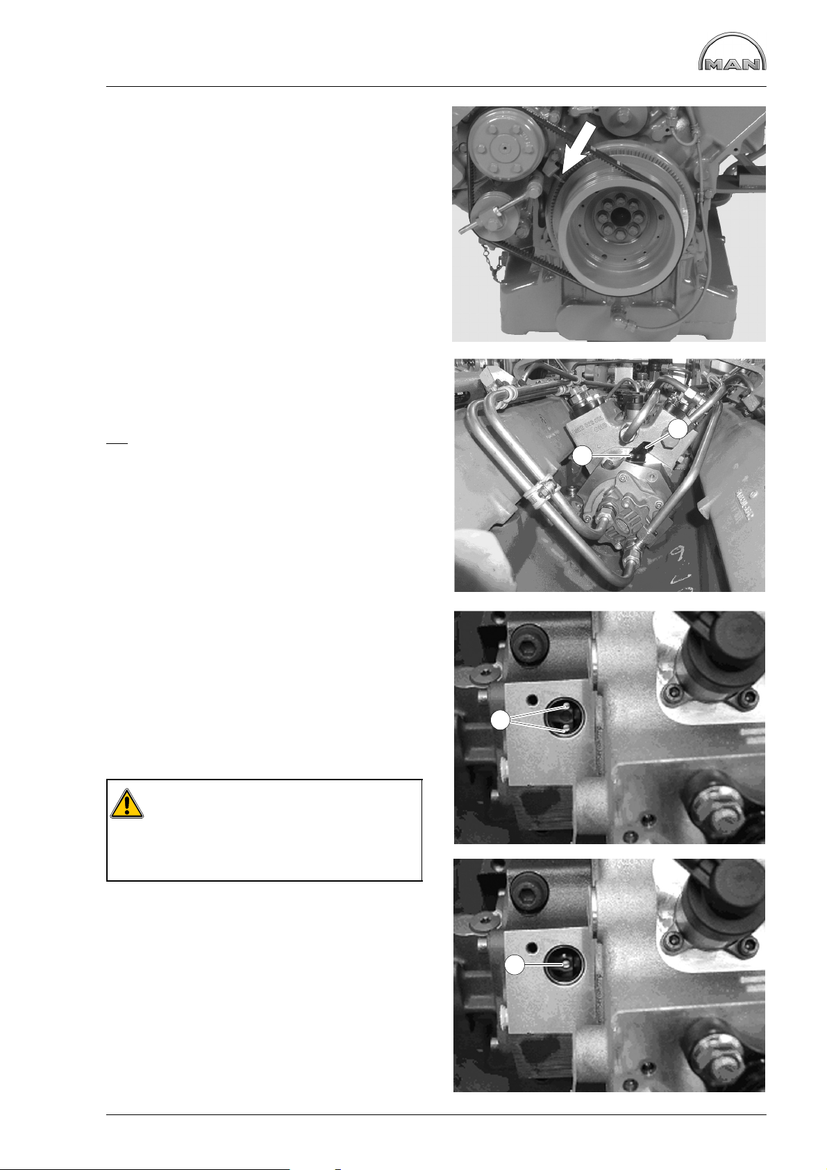
Fig. 5
The indicator (arrow) must then be aligned so that
its measuring edge points exactly to the “TDC”
mark on the scale disc.
Turn engine to ignition TDC 1.
Fig. 6
Pull the connector off the rpm sensor Á.
Unscrew the mounting bolt À of the rpm sensor Á
and pull out the rpm sensor.
marking may be visible.
No
Fig. 7
If the engine is now turned back to 69° before
TDC, 2 markings À must be visible.
If both markings are visible, then fit the rpm sensor
and tighten the mounting bolt with 9 Nm.
Reconnect the control unit.
5
2
1
7
1
Fig. 9
Caution:
If only 1 marking is visible, the high−pres-
sure pump has been fitted and twisted by
180° towards ignition TDC engine cylinder 1.
In this case, the high-pressure pump has to be removed.
8
1
9
25
Page 28
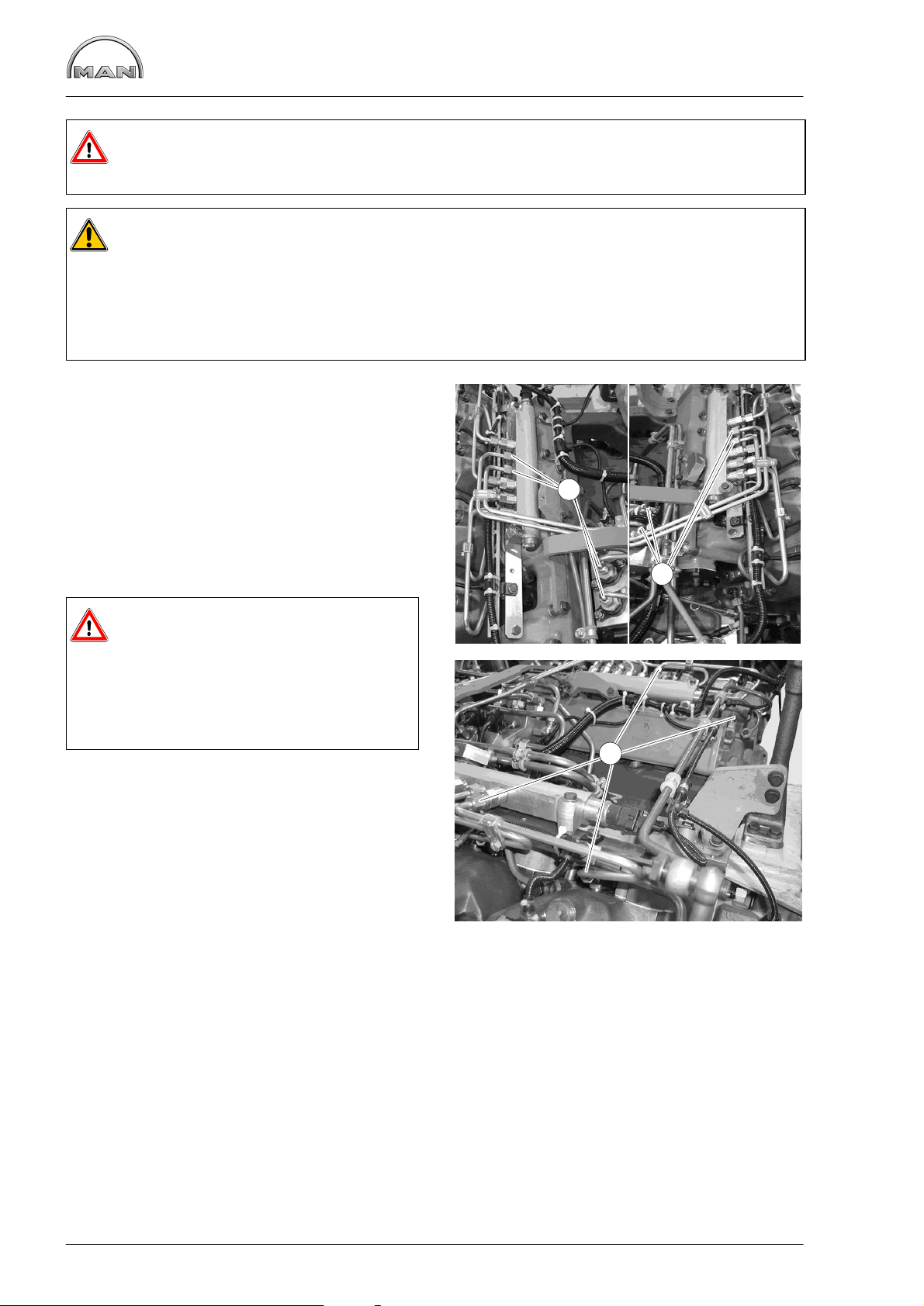
Removing and installing the high-pressure lines
Danger:
Before starting the work, comply with “Special instructions when working on the common rail system” (see page 9).
Caution:
All connections and removed parts are to be closed immediately with suitable caps!
Dirt in the injection system causes:
D injectors to jam
D the high-pressure pump drive to break
The lines contain fuel.
Catch escaping fuel in a suitable container.
Fig. 1
Unscrew the union nuts À of the high-pressure
lines between the rail and high-pressure pump.
Fig. 2
Unscrew the union nuts Á of the high-pressure
lines between the rail and injectors.
The lines are installed in reverse order.
Danger:
High-pressure lines with WAF 17 union
nuts must be replaced!
High-pressure lines with WAF 19 union
nuts may be reused!
Injection lines must be fitted without tension.
Tightening torques for high-pressure lines:
Initial fit:
Pretightening 10 Nm
Final tightening 60°
Reuse:
Pretightening 10 Nm
Final tightening 30°
1
1
1
2
2
26
Page 29
Removing and installing high-pressure pump
Removing high-pressure pump
D Remove the high-pressure lines between the high-pressure pump and rail, see page 26
Note:
The subsequent reinstallation of the high-pressure pump is rendered considerably easier if before
its removal the engine has been turned to ignition TDC cylinder 1(see page 24).
Danger:
Before starting the work, comply with ”Special instructions when working on the common rail system” (see page 9).
Fig. 1
Unscrew and remove all fuel and oil lines to the
high-pressure pump Á and to fuel distributor Â.
Undo all the electrical connections to the highpressure pump.
3
Caution:
All connections and removed parts are to
be closed immediately with suitable
caps!
The lines contain fuel!
Catch escaping fuel in a suitable container.
Note:
To facilitate reassembly, memorise or
mark down in a drawing or photo the
positions of the brackets, pipe clamps
and spacer sleeves etc.
To remove the injection pump, the high-pressure
pump drive must be made accessible.
For this purpose the fuel distributor must be detached.
Close shutoff valve from tank to engine.
Fig. 2
Remove timing case cover.
2
1
1
2
The injection pump drive can now be seen.
Fig. 3
Remove mounting bolts from high-pressure pump
(arrow).
Take off high-pressure pump.
3
27
Page 30
Removing and installing high-pressure pump
Installing high-pressure pump
D Turn engine to ignition TDC 1.
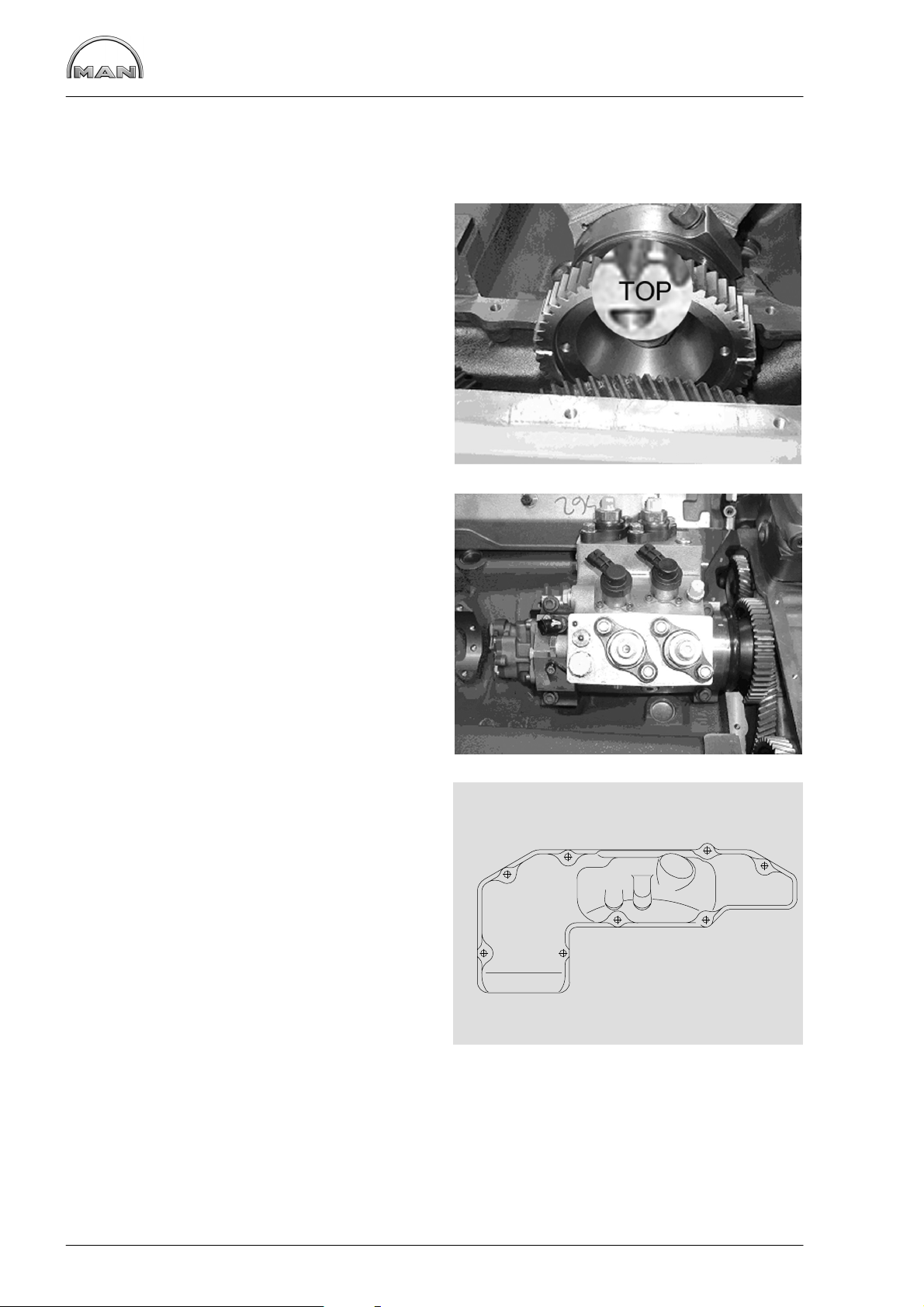
Fig. 4
Turn mark “TOP” on the high-pressure pump drive
gear in the middle to pump.
Insert high-pressure pump.
Fig. 5
4
Tighten the mounting bolts in the sequence and
method specified (pos. 1−4).
Order of tightening: 1−2−3−4 in the steps:
1. Initial torque: 10−15 Nm
2. final torque: 65−70 Nm
Check the base fitting of the high-pressure pump,
see page 24.
Fig. 6
Tighten bolts on timing case cover to the torque
and in the sequence specified.
Tightening torque: 25 Nm
Refit all components previously removed.
3
2
5
1
5
42
87
1
4
3
6
28
6
Page 31

Removing and installing the rail
Danger:
Before starting the work, comply with “Special instructions when working on the common rail system” (see page 9).
Caution:
All connections and removed parts are to be closed immediately with suitable caps.
Dirt in the injection system causes:
D injectors to jam
D the high-pressure pump drive to break
The lines contain fuel.
Catch escaping fuel in a suitable container.
Fig. 1
D Close shutoff valve from tank to engine
Caution:
Before the high-pressure lines are removed
it is necessary to clean the CR system again.
7
Unscrew the union nuts Æ of the high-pressure
lines between the rail and injectors.
Fig. 2
Unscrew the union nuts Ç of the high-pressure
lines between the rail and high-pressure pump.
Fig. 3
Remove fuel pipe for rail return.
Take out rail É.
1
8
8
2
29
10
10
3
Page 32

Removing and installing the rail
Install rail
Install the filter in reverse order:
D Install rail and fuel pipe for rail return
D Fit high-pressure pipes
Danger:
High-pressure lines with WAF 17
union nuts must be replaced.
High-pressure lines with WAF 19
union nuts may be reused.
Injection lines must be fitted without
tension.
Tightening torques for high-pressure lines:
Initial fit:
Pretightening: 10 Nm
Final tightening:60°
Reuse:
Pretightening: 10 Nm
Final tightening:30°
D Install intake neck and bleed pipes
D Vent the fuel system, see page 38
30
Page 33

Removing and installing the rail pressure sensor,
pressure relief valve
Danger:
Before starting the work, comply with “Special instructions when working on the common rail system” (see page 9).
Caution:
All connections and removed parts are to be closed immediately with suitable caps!
Dirt in the injection system causes:
D injectors to jam
D the high−pressure pump drive to break
The lines contain fuel.
Catch escaping fuel in a suitable container.
Fig. 1
Remove the rail pressure sensor À or pressure
relief valve Á from the rail. Undo the electrical connection of the rail pressure sensor.
1
Fit the rail pressure sensor À or pressure relief
valve Á on the rail.
Tightening torque:
Rail pressure sensor À 70 Nm
Pressure relief valve Á 100 Nm
Reconnect the rail pressure sensor.
2
2
31
Page 34

Removing and installing the injectors
Danger:
Before starting the work, comply with ”Special instructions when working on the common rail system” (see page 9).
Caution:
All connections and removed parts are to be closed immediately with suitable caps!
Dirt in the injection system causes:
D injectors to jam
D the high-pressure pump drive to break
The lines contain fuel!
Catch escaping fuel in a suitable container.
Removing injectors
D Close shutoff valve from tank to engine
D Removing rail, see page 29
D Draining off coolant, see page 40
Fig. 1
Remove the cylinder head covers.
Fig. 2
Remove the cable lugs on the injector.
Caution:
There are small copper washers under the
cable lugs; these could fall into the en-
gine!
Fig. 3
1
2
Remove the valve cover seal.
Remove mounting bolts from carrier for injector
cable harness and slew carrier to one side.
3
32
Page 35

Removing and installing the injectors
Fig. 4
Remove coolant bleed pipe, rail carrier and leak-oil
pipe.
Fig. 5 and Fig. 6
Unscrew the mounting bolt Á of the connector fitting and pull the pressure pipe fittings  out of the
cylinder head.
4
Fig. 7
Unscrew the mounting bolt of the pressure flange
(see item À Fig. 6).
5
1
2
3
6
33
7
Page 36

Removing and installing the injectors
Fig. 8
Use a support bridge À and extractor tool Á (see
page 172) to pull out the injector and pressure
flange.
D Push the extractor tool Á through the support
bridge À over the injector, making sure that
the clamping sleeve is turned back far enough
D Tension the clamping sleeve and pull the injec-
tor with knurled nut out of the cylinder head
Danger:
Injectors must not be opened!
Caution:
Immediately close off the connection
openings of the injector with suitable caps
(see page 172) and place in the storage
sleeve.
Clean the injector seat in the nozzle bushing.
1
2
8
1
2
Fitting injectors
Fig. 9
Insert new O-ring À and new copper sealing ring
Â.
Grease the O-ring.
Figs. 10 and 11
Insert the injector with pressure flange into the
nozzle bushing in such a way that the feed bore
hole Á (see also item Á on Fig. 9) points to the
bore hole for the pressure pipe À in the cylinder
head.
Press in the injector by hand as far as it will go.
Pretighten the mounting bolt for pressure flange
with 1.5 Nm.
3
9
10
1
11
34
2
3
Page 37

Removing and installing the injectors
Fig. 11 and Fig. 12
Caution:
Removed pressure pipes must be replaced.
Insert pressure pipe into the cylinder head.
Caution:
The thin end of the pressure pipe points
towards the injection nozzle.
Replace the O-ring and apply a light coating of
grease.
Insert the connector fitting and align in such a way
that the high-pressure line can be connected without tension (see also item Á Fig. 6).
Pretightening: 10 Nm
Fully tighten the mounting bolt for pressure flange
(see also item À Fig. 6).
Final tightening: 25 Nm
Angle tightening: 905
12
Fully tighten the mounting bolt for connector fitting
(see also item À Fig. 6).
Final tightening: 20 Nm
Angle tightening: 905
Check tightness of injector, pressure
pipe and leak-oil line
Caution:
After the injectors have been installed, always check to ensure that the injectors,
pressure pipes and leak-off oil lines do not
leak.
Note:
The check for leaks can only be performed for one row of cylinders at a time.
Fig. 13 and Fig. 14
D Remove the high-pressure lines to the individ-
ual cylinders on the rail or on the connector fitting
D Connect test device Á up to the ring piece of
the leak-oil pipe À
D Pump approx. 2 bar pressure to fuel system
The pressure must not drop for a period of 3 minutes.
If there is a leak in the fuel system, the injectors
have to be removed once again. Check the removed parts for damage or soiling - replace if
necessary and then refit, observing the greatest
possible cleanliness.
13
14
1
1
2
35
Page 38

Removing and installing the injectors
Fig. 15
Install rail carrier, coolant bleep pipe and cable harness for injector.
Connect cable harness to the injectors.
Tightening torque: 1.5 Nm
Fig. 16
Fit valve cover with seal and
tighten mounting bolts.
D Installing rail, see page 30
D Fill coolant, see page 40
15
16
36
Page 39

Fuel prefilter with water separator
Fuel pre-filter with water separator
Fig. 1
Draining water:
D Open drain screw À and let off water
D Close drain screw À again
Changing filter element
Only when the engine is switched off
Close shut-off valves between engine, pre-filter
and tank.
D Disconnect plug
D Remove filter bowl Á and filter element Â
D Wet seal on new filter with fuel
D Screw on filter  and filter bowl Á
D Connect plug
D After this, bleed the fuel system
D Check filter for leaks
Caution:
Used fuel filters are classed as dangerous waste and must be disposed of accordingly.
3
2
1
1
37
Page 40

Fuel filter, exchanging filter cartridge
Changing fuel filter cartridge
Only when the engine is swiched off.
Close shut-off valves between engine, pre-filter
and tank.
Fig. 1
D Loosen filter cartridge by means of tape
wrench, unscrew it by hand and take it off
D Moisten the seals on the new filter cartridge
with fuel
D Screw on the filter cartridges and tighten them
vigorously by hand
D Bleeding the fuel system
D Check filter for leaks
Caution:
Used fuel filters are classed as dangerous waste and must be disposed of accordingly.
1
Bleeding the fuel system
To bleed the fuel system follow the instructions of the vehicle manufacturer.
38
Page 41

Flame-starter sheathed-element glow plug,
removing and installing
Removing sheathed-element glow plug
Fig. 1
Disconnect the electric connections from the
sheathed-element glow plug.
Remove fuel line carefully.
Loosen counter nut on sheathed-element glow
plug and remove glow plug.
Installing sheathed-element glow plug
Fig. 2
Turn counter nut on sheathed-element glow plug
upwards until it stops and apply “Curil T” sealant to
threaded portion.
Screw in sheathed-element glow plug with new
sealing ring until it stops at the counter nut and
align it with fuel line.
1
Connect up fuel line and electric connection.
Tighten counter nut.
Checking solenoid valve for leaks
Remove fuel line from flame glow plug.
When the engine is running and hot, no fuel must
emerge.
Removing solenoid valve
Fig. 3
D Detach fuel lines. Ensure that insulation el-
ement does not burst.
D Remove electric connection from valve
D Remove the two hex bolts and take off valve
The valve cannot be repaired.
Exchange the defective valves.
Fitting solenoid valve
2
3
D Screw valve to holder
D Screw on electric connection
D Refit fuel lines with new seals. Ensure that in-
sulation element does not burst.
4
39
Page 42

Draining and filling coolant
Draining coolant
Danger:
When draining hot coolant, there is a
danger of scalding!
Drain coolant as follows when cooling system has
cooled down:
Caution:
Collect the drained coolant and dispose
of it in accordance with regulations!
Fig. 1 and Fig. 2
1
1
To let off pressure briefly open cap on filler neck of
expansion tank.
Observe the vehicle manufacturer’s instructions.
Open drain plug in crankcase À or in the oil cooler
housing
Catch emerging coolant in a suitable container.
Á.
2
2
Fill / bleed the cooling system (only when engine has cooled down)
The cooling system of the engine is to be filled with a mixture of drinking water from the mains and antifreeze based on ethylene glycol and / or anticorrosion additive.
See Publication “Fuels, Lubricants and Coolants for MAN Diesel Engines”.
Coolant must be poured in according to the vehicle manufacturer’s filling specifications.
Do not pour any cold coolant into an engine which is still warm.
Ensure that the mixing ratio “water-antifreeze” is preserved.
D Pour in coolant slowly until the correct coolant level is reached (max. 10 ltr./min.)
D Run the engine briefly and then check coolant level once more
Danger:
If, in exceptional cases, the coolant level on warm engines has to be checked or the cooling circuit
opened, observe the vehicle manufacturer’s safety regulations.
40
Page 43

Removing and installing thermostats
Fig.1
D Draining off coolant, see page 40
Remove the three mounting bolts from the coolant
neck and take off coolant neck.
Fig. 2
Take out short-circuit inserts / thermostats.
Check the function of the thermostats as follows.
D Suspend the thermostat in a bowl of water
D Heat up the water
D Use suitable thermometer to ascertain the
opening start and compare it with the set-point
value given in “Service Data”.
D If necessary, measure the opening stroke
1
Replace defective thermostats.
Insert thermostat inserts ball valve facing upwards
(“TOP”) with new O-ring seal and new seal.
Caution:
Never let engine run without thermostats
or short-circuit inserts.
2
41
Page 44

Removing and installing coolant pump
Note:
Exchange or repair coolant pump only if it has been found to be leaky.
The design of the coolant pump mechanical cassette seal permits small amounts of coolant to
pass through it. This coolant passing through results in a trace of drained coolant below the drain
bore. The coolant pump need not be exchanged or repaired because of this trace of permeating
coolant.
For this reason before exchanging or repairing a coolant pump ascertain
D whether the cooling circuit shows visible and recurring signs of coolant loss; if yes
D whether the coolant loss is caused by spillage from the expansion tank (e.g. too full) or by
other leakages from hoses, radiator etc.
Coolant pumps must be exchanged only if coolant drips visibly while the engine is in operation or
after the engine has been switched off.
Removing coolant pump
D Draining off coolant, see page 40
D Remove the thermostats, see page 41
Fig. 1
Take V-belt off coolant pump, see page 132
Fig. 2
Remove the mounting bolts from coolant pump
Take off coolant pump and delivery start indicator
1
42
2
Page 45

Removing and installing coolant pump
Installing coolant pump
Fig. 3
Clean the sealing faces on coolant pump and engine housing.
Fit coolant pump with new seal.
Fit the mounting bolts.
Fig. 4
Coolant pumps with high-temperature and
low-temperature sections
To aid in assembly pins (special tool, see page
171, no. 43) can be screwed into the crankcase
(arrows, Fig. 3). The water pump can then be fixed
to the protruding pins.
3
Fit the mounting bolts.
There is a screw for removing the pins (special
tool, see page 171, no. 42).
This screw has a left-handed thread and is
screwed into the pin. In this way the two can be
screwed out together.
Fit remaining mounting bolts.
Fig. 5
Tighten the mounting bolts with the prescribed
torque.
Screw coolant hose pipe on to oil cooler.
Install short-circuit inserts / thermostats, , see
page 41.
Refit and tension V-belt, see page 132.
Filling up with coolant, see page 40.
4
5
43
Page 46

Repairing coolant pump with high-temperature
and low-temperature parts
Coolant pump for three thermostats
Fig. 1 and 2
1 Pump housing HT (high-temperature part)
2 Pump housing LT (low-temperature suction
part)
3 Hub
4 Bolt DIN 931−M8x155,
hex nut DIN 934−M8
5 Bolt DIN 933−M8x35−8.8
6 Mechanical seal 51.06520−0085
7 Impeller for coolant pump, HT circuit
8 Mechanical seal 51.06520−0099
9 Counterring complete 51.06520−0100
10 Impeller for coolant pump, LT circuit
11 Splash shield
12 Mechanical seal 51.06520−0096
13 Coolant pump bearing
14 Drive shaft for coolant pump
15 Circlip
16 Coolant pump seal
17 Grooved ball bearing 6003
18 Cap
1
2
3
5
4
1
18
6
7
17
8
9
10
11
16
12
13
Disassembling water pump
Fig. 3
Removing the water pump, see page 42.
Clamp water pump in a vice, use protective jaws.
Pull off boss with three-arm puller.
Fig. 4
Unclip the circlip from the coolant pump housing.
15
2
3
14
44
4
Page 47

Repairing coolant pump with high-temperature
and low-temperature parts
Fig. 5
Knock out cover by driving a suitable mandrel
under it (Fig. 1, item 3) at notch (arrow).
Fig. 6
Pull impeller off coolant pump shaft.
For this purpose four threaded bores M8 are provided.
5
Fig. 7
Note:
Remove bolt from low-temperature part
(Fig. 1, item 5).
Align water pump housing on a suitable and stable
surface.
Use a suitable mandrel to press the water pump
shaft together with bearing out of the housing.
Take off mechanical seal.
The high-temperature part and the low-temperature suction part are now separated.
Remove axial face seals and grooved ball bearing
from high-temperature part if they are still in the
housing.
6
7
45
Page 48

Repairing coolant pump with high-temperature
Reassembling coolant pump
Fig. 8
Press in water pump bearing.
Fit the circlip.
Note:
If you change the seals always install a
new shaft and axial face seals.
Fig. 9
Press boss flush on to bearing shaft.
and low-temperature parts
8
Fig. 10
Turn water pump housing over Press in new mechanical seal with press-fitting sleeve (special tool)
until it stops.
Observe installation note for seal on page 50.
Fig. 11
Press in counterring (arrow) with a suitable pressing tool (may be possible by hand).
Install mechanical seal while “wet”, i.e. to install it,
coat holding sleeve and water pump shaft with a
mixture of either 50% water and 50% cleaning
spirit or 40% to 50% antifreeze agent as per MAN
324 and water.
9
10
11
46
Page 49

Fig. 12
Repairing coolant pump with high-temperature
and low-temperature parts
Note:
Brace the bearing shaft.
Slowly press impeller on to bearing shaft to ensure
correct gap (0,5
Fig. 13
Press in new mechanical seal (pos. 8) with pressfitting sleeve (special tool) until it stops.
Observe installation note for seal on page 50.
+0,4
).
12
13
Fig. 14
Lay coolant pump gasket on pump housing.
Fig. 15
Carefully fit low-temperature suction part to hightemperature pump housing.
To make assembly easier insert 2 pins in opposite
sides of HT part (see Fig. 14)
Do not use force (hammer etc.) and note the 3
centring features (see arrows in Fig. 14).
14
Screw in bolt (Fig. 1, item 5).
Bolt LT and HT parts together with 2 bolts and nuts
on opposite sides (Fig. 1, item 4).
15
47
Page 50

Repairing coolant pump with high-temperature
and low-temperature parts
Fig. 16
Note:
For subsequent steps brace the bearing
shaft.
Press grooved ball bearing 6003 into position using
special tool.
Fig. 17
Press in new mechanical seal (pos. 6) with pressfitting sleeve (special tool) until it stops.
Observe installation note for seal on page 50.
16
Fig. 18
Slowly press impeller on to bearing shaft to ensure
correct gap.
Fig. 19
For this purpose an inspection hole closed up with
a screw plug (M16x1.5) is provided on the bottom
of the water pump housing.
1 Impeller
2 Coolant pump housing
17
18
2
1
19
48
Page 51

Repairing coolant pump with high-temperature
and low-temperature parts
Fig. 20
Fit new pump cover and press it into housing,
using a suitable pressing tool.
Attach water pump with new seal, see page 42.
20
49
Page 52

Repairing coolant pump with high-temperature
and low-temperature parts
Installation note for mechanical seal:
Install mechanical seal while “wet”, i.e. to install it, coat holding sleeve and water pump shaft with a mixture
of either 50% water and 50% cleaning spirit or 40% to 50% antifreeze agent as per MAN 324 and water.
Other antiseize agents must not be used.
Because the seal on collar Á is coated with sealing paint, no sealing paint needs to be applied if the locating bore in the coolant pump housing is in perfect condition.
If the bore shows even the slightest scoring or other minor damage, a sealing bead of Dirko-Transparent,
Part No. , must be applied to collar Á.
Fit the seal with a plastic transportation cap onto shaft À and use installation tool to press it in until the tool
contacts the housing. Remove the plastic cap.
1 2 3 4
5
Note:
Tests have shown that most cases of damage to the coolant pump can be attributed to the use of
unsuitable coolants.
Only the anticorrosion and antifreeze agents expressly approved by MAN Nutzfahrzeuge AG as
per MAN norm 324 (see brochure “Fuels, Lubricants, Coolants for and MAN Diesel Engines”)
guarantee faultless operation
50
Page 53

Cleaning cooling system
Cleaning inside of cooling system
Tests have shown that in many cases the poor condition of the coolant and / or the cooling system accounts for damage to the coolant pump seal. The poor condition of the cooling system is normally due to
the use of unsuitable or no antifreeze or corrosion inhibitor or to defective caps for filler necks and service
valves which are not punctually replaced.
If the coolant pump of an engine develops leaks twice in short succession or the coolant is heavily contaminated (cloudy, brown, mechanically contaminated, grey or black signs of leakage on the coolant pump
housing, after the defect on the oil cooler), clean the cooling system prior to removing the faulty coolant
pump as follows:
a) Drain coolant
b) Open the thermostats positively (use bypass inserts) so that the entire cooling circuit is flushed immedi-
ately during the cleaning operation
c) Fill coolant circuit with a mixture of hot water (min. 50°C) and Henkel P 3 neutrasel 5265 detergent
(1.5% by volume) (−5266, −5225, Kluthe Hakopur 316), refer to Publication ”Fuels, Lubricants ...”
d) Warm up the engine under load. After a temperature of 60°C is reached, run the engine for a further 15
minutes
e) Drain cleaning fluid
f) Repeat steps c) and d)
g) Flush the cooling circuit; to this effect
h) Open the drain valve slightly
i) Fill the cooling circuit with hot water
k) Run the engine at idle for 30 minutes. At the same time, continuously replenish the water emerging
through the drain valve by adding fresh water at the filler neck
l) Drain off cleaning fluid and close the drain valve
Only now should the coolant pump be repaired. On completion of repairs, fill the cooling system with coolant, refer to publication “Fuels, Lubricants ...”.
Note:
Only sediments and suspended particles can be removed by this cleaning method. If rust and lime
deposits are detected, proceed following the instructions set out in the section below:
51
Page 54

Cleaning cooling system
Removing lime deposits in cooling system
Proceed as follows:
D Drain coolant
D Fill the system with undiluted original pickling fluid (lithsolvent acid or engine pickling fluid RB-06). Keep
the engine running for approx. 8 hours with this fluid in the system (also in normal operation)
D Drain the pickling fluid and flush the system thoroughly with tap water
D If necessary, refill the system with fresh pickling fluid and pickle the system for a further 8 hours
D Drain the pickling fluid, fill the system with tap water, and run the engine at idle for 5 minutes to flush out
all fluid; then drain the water
D Fill the system with soda solution (1%). Drain the soda solution after running the engine at idle for 5 min-
utes, and flush with tap water until the discharging water runs clear
D Fill cooling circuit with a mixture of potable tap water and anti−freeze with at least 40% by volume, refer
to Publication ”Fuels, Lubricants ...”
Filler caps and service valves of cooling system
The rubber seals on the filler caps and service valves (negative pressure and positive pressure valves) of
the cooling system are subject to natural ageing.
To prevent leakages in the cooling system together with the associated loss of pressure and its consequences through to serious engine damage, replace the filler caps and service valves at the same time as
changing the coolant (every two years at the latest).
Waste water treatment
Drained and spent cleaning and pickling fluid should be brought up to a pH value of 7.5 to 8.5 with the aid
of caustic soda. Once the precipitation has settled to the bottom of the container, the clear fluid above can
be tipped into the sewer system. To be sure, it is advisable to consult the local authorities for more information on waste water rules and restrictions. The sludge at the bottom must be taken to a special waste
dump.
52
Page 55

Changing oil filter
Caution:
Used oil and oil filters are classed as dangerous waste and must de disposed of
accordingly. Note instructions for preventing environmental damage.
Fig. 1
Open oil drain plug on oil filter can and use container to catch oil that may emerge.
Danger:
Oil filter can and oil filter are filled with hot
oil.
Risk of burns and scalding.
Fig. 2
Remove mounting bolt of filter bowl.
1
Take off filter bowl and clean it internally.
Fig. 3
Insert new filter element and fit filter bowl with new
seals.
Refit oil drain plug with new seal.
Observe tightening torque for mounting bolt.
Note:
To prevent the seal from twisting hold the
filter bowl firmly when tightening the tensioning screw.
Top up with engine oil, let engine run briefly and
then check for leaks.
2
3
Check oil level.
53
Page 56

Removing and installing the oil cooler
D Draining off coolant, see page 40
D Removing the oil filter, see page 53
Caution:
Old oil and used oil filters are hazardous
waste.
Observe safety instructions for the prevention of environmental damage.
Fig. 1
Remove oil filter head (5 screws).
Remove filter head gasket.
Fig. 2
Unscrew oil cooler housing cover with fitted oil
cooler.
The 10 marked screws hold the oil cooler. Only
loosen these screws after removing the housing
cover.
Fig. 3
Check both oil cooler for damage and if necessary
replace them. Fit oil cooler with new gaskets.
1
2
Fig. 4
Tighten the mounting bolts with the prescribed
torque.
D Screw on oil cooler housing cover with fitted oil
cooler
D Attach oil filter head and oil filter with new
seals, see also page 53
D Fill engine oil and check for leaks after a short
engine run
D Check oil level
D Filling up with coolant
3
4
54
Page 57

Removing and installing, repairing oil pump
Drain engine oil
Danger:
The oil is hot, risk of scalding! Do not
touch the oil drain plug with bare fingers.
Oil is an environmental hazard. Handle
with care!
Fig. 1 and Fig. 2
With the engine at operating temperature, remove
the oil drain plugs on the oil sump and the oil filter
bowl and allow the old oil to drain off completely.
Use a suitable container of sufficient capacity here
to prevent oil from overflowing.
Caution:
Old oil is hazardous waste.
Observe safety instructions for the prevention of environmental damage.
1
Remove oil pan
Caution:
Oil pans are awkward to handle and
heavy.
They may contain residual amounts of
engine oil.
Use lifting gear or work with a helper.
Fig. 3
Remove the mounting bolts from oil pan.
Take off oil pan.
Removing oil pump
Fig. 4
Remove the mounting bolts from the bracket and
from the oil pump.
2
3
Take off oil suction pipe.
Measure backlash between oil pump drive gear
and crankshaft gear and compare value with the
nominal value.
Replace worn gears.
4
55
Page 58

Removing and installing, repairing oil pump
Fig. 5
Unscrew the mounting bolts of the pressure relief
valve and oil pump.
Take off overpressure valve and oil pump.
The overpressure valve is encapsulated.
Opening pressure, see “Service Data”.
Note:
Depending on the engine model and oil
pan variant, various oil pump versions are
possible.
Repairing oil pump
Fig. 6
Fit the oil pump in a vice (use protective jaws).
5
Remove oil pump cover.
Fig. 7
Pull the driven oil pump wheel from the casing.
Check the toothed wheels and pump casing for
wear (see “Service Data”).
Fig. 8
6
7
Remove oil pump drive gear.
To do this, lay pump on suitable support and press
off drive gear using a mandrel.
To install it, put drive gear on shaft, supporting
facing shaft end.
Press on the drive wheel, observing the prescribed
gap (see “Service Data”).
8
56
Page 59

Removing and installing, repairing oil pump
Fig. 9
Fit on the cover.
Tighten the mounting bolts with the prescribed
torque.
Grind or exchange heavily worn covers.
Checking the axial clearance of the
pump wheels
Fig. 10
Position dial gauge and push shaft up to the stop
in one direction and set dial gauge to ”0”.
Push the shaft in the opposite direction and read
off the needle deflection on the dial gauge.
Installing oil pump
Fig. 11
Tighten the mounting bolts with the prescribed
torque.
D Before installing, check whether the oil pump
run smoothly and then fit it / them free of ten-
sion
D Fit oil suction line À with seal in a tension−free
manner
D Screw on pressure−relief valve Á without seal
10
9
1
2
Before fitting the oil pan, run the engine to check
that the crankshaft drive and oil pumps are running
smoothly and easily.
Attaching oil pan
Fig. 12
Fit an oil pan seal.
Fit oil pan to crankcase and screw in the mounting
bolts.
Tighten the mounting bolts with the prescribed
torque.
11
12
57
Page 60

Removing and installing, repairing oil pump
Filling with engine oil
Caution:
Do not add so much engine oil that the oil
level rises above the max. marking on the
dipstick. Overfilling will result in damage
to the engine.
Fig. 13 and Fig. 15
Refill with fresh engine oil at the oil filler neck À.
After filling with oil disconnect electric connection
from speed pickup. Turn engine over with starter
until oil pressure warning lamp goes out / oil pressure gauge indicates pressure. Then restore electric connection to speed pickup. Then start the engine and allow it to run at medium speed for a few
minutes. Check oil pressure and leaks.
Then shut down the engine. After about 20 minutes, check the oil level.
D Pull out dipstick
D wipe it with a clean, lint−free cloth
D and push it in again up to the stop
D Pull out dipstick again
1
13
The oil level should be between the two notches in
the dipstick and must never fall below the lower
notch. Top up oil as necessary. Do not overfill.
14
15
1
Oil
?
1
MAX
MIN
58
Page 61

Oil injection nozzle
Removing the oil injection nozzle
D Draining off oil, see page 55
D Removing the oil pan, see page 55
Fig. 1
Unscrew the securing bolts of the oil injection
nozzle (arrow).
Remove oil injection nozzle with valve.
Check the oil injection nozzle valve
Fig. 2
Unscrew the oil injection nozzle valve from the
body of the oil injection nozzle.
The valve plunger must move up and down easily.
If the valve plunger sticks or jams, replace the oil
injection nozzle valve.
Opening pressure, see “Service Data”.
Installing the oil injection nozzle
Fig. 3
Position the oil injection nozzle À at the oil injection nozzle flange Á.
1
2
Fig. 4
Tighten the securing bolts with the prescribed
torque.
59
2
3
4
1
Page 62

Oil injection nozzle
Fig. 5
The oil spray from each nozzle must reach the
entry bore hole of the cooling duct in the piston
crown À and cams Á without hindrance.
Bent oil injection nozzles must on no account be
repaired.
Turn the engine. The crankshaft drive or pistons
must not collide with the oil injection nozzle.
2
1
1
1
2
2
1
5
60
Page 63

Removing and fitting vibration damper,
replacing front crankshaft gasket
Removing vibration damper
D Relax and remove V-belt; see page 132
D Turn engine to ignition “TDC”. This ensures that
in subsequent assembly work the indicating dial
will be in the correct position
Fig. 1
Block the crank gear.
The illustration shows a special tool that is to be
fitted to the inspection port of the flywheel housing.
Fig. 2
Loosen the securing screws of the vibration
damper.
1
Fig. 3
Unscrew the two mounting bolts opposite one
another and screw in the guide mandrel (M16x1,5).
Remove all remaining bolts.
Remove the vibration damper.
Caution:
The vibration damper is sensitive to impacts.
Remove oil thrower from the crankshaft.
2
3
61
Page 64

Removing and fitting vibration damper,
replacing front crankshaft gasket
Replacing the front crankshaft gasket
Fig. 4
Loosen the mounting bolts of the cover.
Fig. 5
Remove the cover.
Only replace the front crankshaft gasket as a complete unit,
i.e. replace the bearing race and the radial shaft
sealing ring.
4
Replacing the bearing race
Fig. 6
A stripping device (special tool) is required to remove the bearing race.
Fig. 7
Pull off the bearing race.
5
6
62
7
Page 65

Removing and fitting vibration damper,
replacing front crankshaft gasket
Fig. 8
A special too is required to fit the bearing race.
Clean the inside of the bearing race and tail shaft.
Coat the tail shaft with sealing compound
“Antipor 46”.
D Push race À and pressing sleeve Á onto
adapter Å
D Tighten spindle Ä in adapter Å with nut Æ
D Bolt adapter Å to crankshaft
Fig. 9
The adapter must lie free of clearance on the
crankshaft so that the right press−in depth of the
bearing race is ensured.
Pull the bearing race as far as it will go into the
press−in sleeve Á on the adapter with collar nut
and thrust washer ( and à in Fig. 9).
Note:
The bearing race can also be mounted
when the cover is fitted.
1 2
7
8
4
356
Replacing the radial shaft sealing ring
Fig. 10
To ensure perfect installation, the replacement
cover and shaft sealing ring are only delivered as a
complete unit.
So that it remains possible to mount the shaft sealing ring, it must stay on the transport and installation sleeve until assembly.
Refer to the comments and assembly instructions
on page 69.
Fig. 11
Fit cover À with new gasket Á.
The cylinder pins  provide better guidance for the
cover.
The sealing ring is thus not damaged so easily
when the cover is replaced.
Tighten the bolts with the prescribed torque.
10
9
2 51
2
1
11
63
3
Page 66

Removing and fitting vibration damper,
replacing front crankshaft gasket
Fitting the vibration damper
Fig. 12
Position the oil thrower on the crankshaft.
Position the vibration damper on two guide mandrels (M16x1.5). Ensure that the position of the
graduated disc relative to the crankshaft is correct.
Tighten the mounting bolts with the prescribed
torque.
Fit cranking device.
Fit and tension V-belts, see page 132
Fig. 13 and Fig. 14
During assembly the delivery start indicator on the
vibration damper may have moved out of correct
adjustment.
This is why you should check whether the scale of
degrees on the inspection hole cover of the flywheel housing (picture 14) and on the vibration
damper (picture 15) indicate the same values.
If necessary readjust delivery start indicator.
Caution:
Unblock the crankshaft drive!
12
13
14
64
Page 67

Removing and installing flywheel,replacing starter gear ring
Removing flywheel
D Remove speed pickup, see page 133
Fig. 1
Release the mounting bolts, securing the engine
against rotating if necessary.
Fig. 2
Unscrew two bolts opposite one another and replace with two guide mandrels (special tool).
Remove all the bolts.
Pull off the flywheel with suitable lifting gear.
1
Danger:
The flywheel is heavy.
Use lifting gear.
Fitting the flywheel
Fig. 3
Insert the guide pins.
Coat the sealing face on the inside of the flywheel
with “Antipor 46” sealing compound.
Place guide mandrels on the flywheel; in doing so,
pay attention to the assignment of the centring pin
(arrow) to the hole in the flywheel.
Push the flywheel on as far as it will go.
Fig. 4
Lightly oil new mounting bolts (elasticated bolts),
screw them in and tighten alternately on opposite
sides of the ring gear to specified torque.
2
3
D Install speed pickup, see page 133
4
65
Page 68

Removing and installing flywheel,replacing starter gear ring
Replacing starter ring gear
Fig. 5
Remove the flywheel.
Drill the starter motor toothed wheel and break
with a chisel.
Caution:
In doing so, do not damage the flywheel.
Fig. 6
Note:
As the maximum axial run-out of the
starter motor toothed wheel must not be
exceeded, the axial run-out of the flywheel should be measured on the contact
surface of the starter motor toothed
wheel prior to shrinking on the starter
motor toothed wheel.
If the required value is exceeded, replace
the flywheel.
5
Engage the flywheel at the hub.
Apply the dial gauge to the contact surface of the
toothed wheel.
Turn the flywheel a few revolutions by hand and
observe the reaction of the dial gauge.
Fig. 7
Heat the new starter ring gear to approx. 200°C to
230°C and press on as far as it will go.
Danger:
The parts are hot! Risk of burns.
Wear protective gloves.
Check the axial runout and compare with the max.
permissible value.
6
7
66
Page 69

Replacing crankshaft seal
(flywheel end)
Removing shaft sealing ring
Fig. 1
Remove flywheel, see page 65.
Prisey out the insulation ring with the special tool
or a screwdriver
Fit shaft sealing ring
Fig. 2
When fitting a new shaft seal, you should also exchange the bearing race of the flywheel.
1
Insert the new shaft sealing ring into the flywheel
housing.
Use mandrel (special tool) to drive in sealing ring
until flush.
Refer to the comments and assembly instructions
on page 69.
3
67
Page 70

Replacing the bearing race
Replacing bearing race
Remove flywheel, see page 65.
Fig. 1
If the shaft sealing ring on flywheel side is replaced, it is also recommended to replace the
bearing race of the flywheel.
Pull off the bearing race to be exchanged using a
puller (special tool, see Page163, no. 12.2).
Fig. 2
Insert the new bearing race in the drift (special
tool) in such a way that the inner bevelled side
faces the flywheel when fitted later.
Carefully warm up the drift with bearing race.
The installation temperature of the bearing race is
approx. 150_C.
1
Fig. 3
Press in the bearing race as far as it will go.
Fig. 4
Seal the gap between flywheel and bearing race
with “Antipor 46”.
2
3
68
4
Page 71

Crankshaft gaskets
General information on crankshaft seals
As a general principle, the radial shaft sealing rings are made of polytetrafluorothylene (PTFE), otherwise
known as Teflon.
PTFE sealing rings differ from the elastomer sealing rings that used to be common in that they have a
much wider, flat sealing lip that is not pretensioned by a coiled spring expander.
The relatively large pretension of the sealing lip itself means that it curves inwards. This is why the PTFE
sealing ring is delivered on a transport sleeve. So that it remains possible to mount the sealing ring, it must
stay on this sleeve until assembly. This applies also because the sealing lip is very sensitive and the
smallest damage causes leaks.
The sealing lip and the bearing race of the flywheel must not be coated with oil or other lubricants.
On fitting the new sealing ring, always replace the bearing race alongside it.
Assembly instructions for crankshaft seals
D The PTFE sealing ring must be fitted absolutely free of oil and grease. Even the slightest traces of oil on
the bearing race or sealing ring will cause leakage
D Clean oil, grease and corrosion protection agents from the bearing race before assembly. All standard
cleaning agents can be used here
D If the PTFE sealing ring is soiled with oil or grease, it is unusable. Cleaning is not permitted in this in-
stance
D The PTFE sealing ring must never be stored without the supplied transport sleeve. Even after it has
been stored for a period of only 30 minutes without the transport sleeve, it will lose it pretension and
thus be rendered unusable
69
Page 72

Removing and installing intake manifold
Note:
When carrying out work on the intake
system, ensure meticulous cleanliness to
prevent dirt and foreign matter from penetrating into the system.
Removing intake manifold
Fig. 1
Removing intake manifold.
Remove the injection lines, see page 32
Fig. 2
Remove the mounting bolts from the charge-air
pipe.
1
Fig. 3
Remove the mounting bolts from the intake pipe.
Remove the intake pipe.
Installing intake pipe
Fig. 4
Place intake manifold with new seals in position.
Fit the mounting bolts.
Ensure that the seals are correctly seated.
Tighten the mounting bolts with the prescribed
torque.
2
3
Attach the injection lines.
Fit the charge-air elbow and the charge-air pipes
leading to the turbocharger. Exchange O-ring
seals.
4
70
Page 73

Removing and installing exhaust pipe
Removing the exhaust pipe
D Removing the turbocharger, see page 75
Fig. 1
Remove the guard plates.
Fig. 2
Note:
The exhaust-gas pipe can be removed
along with the attached turbocharger.
Loosen the securing bolts of the exhaust pipe.
Danger:
The exhaust pipe is heavy.
1
Before unscrewing all securing bolts, if appropriate
replace 2 bolts by stud bolts as guides.
The stud bolts with thread M10 have been produced by MAN.
Remove exhaust pipe.
Installing the exhaust pipe
Fig. 3
Before fitting the exhaust pipe, screw in 2 stud
bolts as a guide.
Position the exhaust pipe with new gaskets.
Ensure that the gaskets are correctly seated.
Fig. 4
2
3
Tighten the securing bolts with the prescribed
torque (see “Service Data”).
D Installing turbocharger
4
71
Page 74

Turbocharger, trouble shooting
Before removing the turbocharger carry out the following checks
Turbochargers are frequently exchanged if the oil consumption is too high, the output too low or the intake
and / or exhaust gas noises appear to be abnormal.
Subsequent inspections by the manufacturer of the supposedly defective parts frequently prove the turbochargers to be in order.
To ensure that only defective turbochargers will be exchanged in future, the following checks are to be carried out beforehand:
If the oil consumption is too high
− Check air filter for contamination
− ensure that the engine room ventilation is adequate
− check intake pipe for cross section reduction (owing e.g. to damage, contamination)
These causes lead to higher oil consumption owing to the increased vacuum on the intake side of the compressor.
− Check outside of turbocharger for oil traces
Oil consumption caused directly by turbocharger depends on the bearing wear and results in relatively early
mechanical damage.
If engine performance is not satisfactory
Correct adjustment of the
− delivery start
− valve clearance
− speed adjustment (to full load stop)
In addition, the following are to be checked:
− the compression
− the air filters for contamination
− the charge-air pressure
− intake system for reduction of cross-section and for leaks
− exhaust system for damage and leaks
If you do not detect any possible cause in the above checks, check the turbocharger for:
− Carbonization in the turbine area, which impairs the movement of the wheel assembly
(can be eliminated by axial movement)
− Dirt in the compressor area
− Damage caused by foreign objects
− Scraping of the turbine rotor on the housing
If a considerable amount of dirt has accumulated, clean the compressor end and check the bearing
clearance.
Caution:
Do not damage the aluminium compressor wheel.
When there is unusual intake or exhaust noise
− Check the intake and exhaust system in the area of the charger group.
Defective gaskets can lead you to think the turbocharger is defective. Replace them.
− If there are still unusual noises, check the bearing clearance.
Turbochargers in good working order do not make any excessive noise.
72
Page 75

Turbocharger, trouble shooting
Oil accumulation in charge-air lines and the intercooler
A small amount of oil collects in the charge-air system. This is supposed to happen, is caused by oil mist,
and is desirable. The oil mist is required to lubricate the intake valve seats.
If more oil accumulates than usual, that is, if oil pockets develop in the lower air box of the intercooler, for
example, this can lead to oil disintegration or uncontrolled raising of the engine speed when the oil is separated. In such cases, you must eliminate the cause.
Possible causes:
− The engine is overfilled with oil
D Check whether the correct dipstick and guide pipe combination is installed
− The engine oil used is unsuitable (see publication “Fuels, Lubricants, Coolants for MAN Diesel Engines”)
− The engine is being run on impermissibly steep inclines
− The crankcase pressure is to high. This may be caused by a defective oil separator valve or piston ring
wear
Compressor carbonization
This can occur when the charge-air temperature is permanently high, for example when the engine is constantly run at full load.
Carbonization lowers the charging pressure but does not negatively affect performance or acceleration.
Carbonization can lead to increased exhaust clouding.
If exhaust emissions test values are no longer met:
− Remove the compressor housing, being careful not to let it get jammed
D If it gets jammed, the compressor wheel blades may get damaged or bent, and the resultant imbal-
ance can ruin the turbocharger
− Remove carbonization in the compressor housing with a suitable cleaning agent
Danger:
Never spray in cleaning agent while the engine is running.
− ineffective
− dangerous
− In problem cases, use oil types that are less likely to lead to compressor carbonisation (see publication
“Fuels, Lubricants, Coolants for MAN Diesel Engines”)
73
Page 76

Checking the charge-air pressure
Sufficient charge-air pressure is indispensable for full power output and clean combustion.
The check is designed to ascertain whether damage to the turbocharger and leaks in the intercooler and in
the charge-air pipes have occurred.
Extreme operating conditions (full-load operation and high air temperature) and the use of unsuitable engine oils (also see publication “Fuels, Lubricants, Coolants for MAN Diesel Engines”) may cause deposits
on the compressor as well as in the intercooler, which results in a reduction in charge-air pressure.
Preconditions for the measurement:
The delivery start and the valve clearance must be set as specified, and the engine must be at operating
temperature.
Charge-air pressure:
A general set-point value for charge-air pressure cannot be given, as the installation conditions have a
bearing on this.
The value ascertained during the commissioning of the engine and noted in the commissioning report is to
be used as the set-point value.
When carrying out the measurement, observe the following:
Owing to various atmospheric reference conditions during the measurements and to tolerances of the pressure gauges used, deviations of max. ± 100 hPa (± 100 mbar) are permissible.
Fig. 1
The measuring connection for checking the
charge-air pressure and the charge-air temperature is located in the intake pipe at the point where
the flame-starter sheathed-element glow plug is
screwed in.
Remove flame-starter sheathed-element glow
plug, see page 39.
Connect up pressure gauge (if necessary using a
suitable threaded pipe as adapter).
1
Fig. 2
Measure the charge-air pressure downstream of
the intercooler at nominal engine speed and full
load.
74
2
Page 77

Removing and installing turbocharger
Removing turbocharger
Fig. 1
Remove the charge−air elbow and the charge−air
pipes leading to the turbocharger.
Fig. 2
Detach intake neck.
1
Fig. 3
Remove oil pressure line from turbocharger.
Fig. 4
Remove oil return line from turbocharger.
2
3
75
4
Page 78

Removing and installing turbocharger
Fig. 5
Remove the bolts from the turbocharger.
Take off turbocharger.
Note:
When placing the turbocharger to one
side, ensure extreme cleanliness to prevent penetration of dirt and foreign
bodies.
Installing turbocharger
Fig. 6
The turbocharger is fitted in reverse order.
On assembly, new gaskets and new self−locking
nuts are to be used.
5
Before connecting the oil supply line, fill the bearing housing with fresh engine oil.
Check all the connections for leaks and to ensure
they are not subjected to strain.
Fig. 7
Note:
Ensure that the clamping area of the
hose is always behind the bead of the
pipe.
1 Pipe
2 Hose
3 Hose clamp
4 Distance
5 Bead on pipe
6
1 2 3
5 4
7
76
Page 79

Checking axial and radial clearance of turbocharger rotor shaft
D Remove turbocharger, see page 75
D Mark turbine housing relative to the bearing
housing
D Remove turbine housing
Axial clearance
Fig. 1
Apply dial gauge holder and dial gauge under preload to shaft end face of the turbine wheel as
shown.
Press rotor shaft against dial gauge. Read and
note down value. Push rotor in opposite direction.
Read and note down value.
The difference between the two is the axial play.
Change turbocharger if axial clearance is exceeded.
1
Radial clearance
Radial clearance is measured only on turbine end
with dial gauge or feeler gauge.
Fig. 2
Dial gauge:
Apply dial gauge tip to side of hub. Push turbine
wheel towards dial gauge. Read and note down
value.
Push turbine wheel in opposite direction. Read and
note down value. The difference between the values is the radial clearance.
Measure at several points.
If the play exceeds the permissible value, exchange turbocharger.
D Fit turbine housing. Ensure that the markings
coincide
D Tighten turbine housing bolts to specified
torque
D Installing turbocharger
2
77
Page 80

Removing and installing the cylinder head
Removing cylinder head
D Drain off coolant, see page 40
D Removing injectors, see page 32
D Remove exhaust pipe, see page 71
D Remove intake pipe, see page 70
Fig. 1
Remove the cylinder head covers.
Remove the coolant bleed pipe.
Detach fuel leak−off oil line.
Caution:
Here, oil residues can escape.
Old oil is hazardous waste.
Observe safety instructions for the prevention of environmental damage.
1
Fig. 2
Back off the valve adjusting screws.
Release and remove the cylinder head bolts in reverse order of tightening.
Remove the rocker arm bearing housing.
Fig. 3
Remove the valve bridges.
Take out the push rods.
Fig. 4
Remove the cylinder head and cylinder head seal.
Check whether the cylinder head sealing face and
cylinder block are flat using a straightedge.
Caution:
The cylinder head sealing face must not
be machined.
2
3
Comply with the specified nozzle projection and
valve recess (see “Service Data”).
Note:
Check the cylinder heads for cracks.
4
78
Page 81

Removing and installing the cylinder head
Installing cylinder head
Fig. 5
Before fitting, clean and blow out the threaded
holes in the crankcase. Clean the sealing surfaces
on the cylinder head and on the crankcase.
Lay the new cylinder head seal in place, ensuring
that the hole patterns match up, and place the cylinder head on top.
Each cylinder head is fixed in position with 2 fitting
sleeves.
Fig. 6
Check the tappet push rod for deformation.
When inserting the tappet push rods, ensure that
they fit in the socket of the valve tappet.
Insert the valve bridges with the cut−through sides
Á facing the push rods.
5
1
2
Fig. 7
Apply a thin bead of “Loctite 5900” sealing compound to seal the rocker arm bearing housing.
Caution:
The bore hole (À in Fig. 6) must be kept
clear for the oil supply!
Fig. 8
Fit the rocker arm bearing housing, inserting the
rocker arm ball pins into the tappet ball sockets.
6
7
79
8
Page 82

Removing and installing the cylinder head
Fig. 9
Check cylinder head bolts for max. permitted
length (see “Service Data”). Removed bolts can be
reused if the max. permitted length is not exceeded.
Before inserting the cylinder−head bolts, apply engine oil to the thread and coat the seating surface
of the bolt head with installation paste “Optimoly
White T”.
Fig. 10
Tighten the bolts according to the rotation angle
method. Observe the tightening sequence, specified tightening method, information and instructions
on the cylinder head bolts in the publication “Service Data”.
Note:
To avoid any distortion between the cylinder heads and exhaust pipes, we recommend proceeding as follows:
D Place the cylinder head seals and
cylinder heads in position
D Screw in the head bolts a few turns
D Fit the straightedge (special tool) with
ground surface on the exhaust side;
tightening torque for mounting bolts: 20
Nm.If a straightedge is not available,
mount the exhaust manifold and tighten
to 20 Nm.
D Tighten the cylinder head bolts as
specified
D Remove the straightedge
D Tighten the exhaust and intake pipes to
specified torque
9
10
Fig. 11
D Installing intake pipe, see page 70
D Installing exhaust pipe, see page 71
D Installing injectors, see page 32
D Set valve clearance, see page 82
D Fit the cylinder head cover with a new seal
D Fill up with coolant, see page 40
11
80
Page 83

Removing and installing the cylinder head
General notes
The sealing effect of the cylinder head seal depends mainly on whether the required initial tension of the
cylinder−head bolt is actually achieved and retained.
To tighten the cylinder−head bolts, use a calibrated torque wrench. The specified final torque must be main-
tained for at least 5 seconds when it is applied. When using snap−type torque wrenches, tighten the bolts
gradually as otherwise the torque selected will not be fully transferred to the bolts.
Observe the notes on the usability of cylinder−head bolts, tightening sequence, and prescribed tightening
method in the chapter “Service Data”.
Tightening
“Tightening” is the initial tightening of the newly fitted bolts that have not yet been tightened following a repair - e.g. after replacement of the cylinder head seal. Tighten the cylinder−head bolts with the engine cold,
i.e. the crankcase is hand−warm or colder.
Before inserting the cylinder−head bolts, apply engine oil to the thread (not the threaded hole) and coat the
seating surface of the bolt head with installation paste “Optimoly White T”.
Do not use oils or oil additives containing MoS
In the case of unoiled bolts, a significant portion of the tightening torque is converted into friction and is thus
lost for the bolt pretensioning.
.
2
D To secure the cylinder heads, tighten the cylinder head bolts only slightly
D Align the cylinder heads by screwing on the straightedge (special tool).
If no straightedge is available, use the exhaust or intake pipe
D Tighten step by step in the right order and with the prescribed tightening torque and / or angle of rotation
Caution:
If individual bolts are tightened too much during preliminary tightening, the cylinder head is distorted. The distortion can no longer be removed with continued tightening in accordance with regulations!
81
Page 84

Setting the valve clearance
Adjust the valves only when engine is cold (max.
coolant temperature 50°C).
Fig. 1
Remove the cylinder head covers.
Caution:
Here, oil residues can escape.
Old oil is hazardous waste.
Observe safety instructions for the prevention of environmental damage.
Fig. 2
Turn the engine using the barring gear until the
piston of the cylinder to be set is at ignition TDC
and the rocker arms are relieved of load.
1
The valves of the synchronised cylinder are then
on overlap.
Fig. 3
D 2842 LE 620
Valves overlap in cylinder
112
6 7 2 11 4 9 1 12 5 8 3 10
Adjust valves in cylinder
Valve clearance:
Fig. 4
D Slide the feeler gauge between the valve bridge
D Loosen lock nut and turn adjusting screw with
D Tighten the lock nut
D Check the clearance once again
D Fit the cylinder head covers:
5 8 3 10 6 7 2 11 4 9
Intake: 0.5 mm
Exhaust: 0.6 mm
and the rocker arm
screwdriver until feeler gauge can be moved
with slight resistance
Tightening torque: 40 Nm
Screw in the bolts by hand and then tighten
2
7
8
9
10
11
12
3
1
2
3
4
5
6
82
4
Page 85

Dismantling and assembling the rocker arm mechanism
Disassembling rocker arm mechanism
D Remove cylinder head, see page 78
Fig. 1
Clamp mounting plate Á (special tool) in a vice and
bolt the rocker arm bearing housing onto the
mounting plate.
The exhaust valve rocker arm shaft has a tapped
hole.
Screw adapter and impact puller À into this tapped
hole.
Fig. 2
Pull out the exhaust valve rocker arm shaft and
remove the rocker arm.
1
2
1
Fig. 3
Drive out the intake valve rocker arm shaft with a
suitable plastic mandrel.
Fig. 4
Remove the rocker arm shaft and rocker arm.
2
3
83
4
Page 86

Fig. 5
Dismantling and assembling the rocker arm mechanism
À Rocker arm shaft for exhaust valves
Á Rocker arm shaft for inlet valves
 Rocker arm
Assembling rocker arm mechanism
Fig. 6 and Fig. 7
Recesses À in the rocker arm shafts serve to accommodate the cylinder head bolts Á.
Align the rocker arm shafts so that the holes for
the cylinder head bolts are kept free.
Lightly oil the shafts and O-rings.
21 3 3
5
1 2
Fig. 8
Press−in device for the rocker arm shafts (special
tools).
À Guide plate
Á Mounting bolts
 Press−in part “A” for exhaust−side shaft
à Press−in part “B” for intake−side shaft
6
7
1
2
84
8
3 4
Page 87

Dismantling and assembling the rocker arm mechanism
Fig. 9
Bolt the guide plate onto the rocker arm bearing
shaft − with “TOP” facing the intake side.
Fig. 10
Insert press−in part “A” for the exhaust−side shaft
into the guide plate, ensuring that the alignment
pins fit into the shaft bores.
9
Fig. 11
Drive the rocker arm shaft fully home into the bearing housing.
Fig. 12
Insert press−in part “B” for the intake−side shaft
into the guide plate, ensuring that the alignment
pins fit into the shaft bores.
Drive the rocker arm shaft fully home into the bearing housing.
10
11
12
85
Page 88

Dismantling and assembling the rocker arm mechanism
Fig. 13
Remove the press−in tool.
Check the rocker arms for ease of movement and
axial play.
13
86
Page 89

Removing and installing valves
Removing valves
D Remove cylinder head, see page 78
Fig. 1
Special tools for removing and installing the valve
springs:
À Assembly plate for cylinder head and rocker
arm bearing housing (not in tool case)
Á Anchor plate with grid part
 Guide sleeve
à Additional guide sleeve for 4−valve cylinder
head
Ä Pressure fork
Å Extension for pressure fork
Æ Assembly cartridge for retaining wedges
Ç Sleeve with large diameter for 2−valve cylinder
head
È Sleeve with small diameter for 4−valve cylinder
head
Depending on the cylinder head, the sleeves are
bolted onto the mounting cartridge.
5
6
4
3
7
8
2
9
1
1
Fig. 2
Secure the cylinder head on mounting plate À.
Fig. 3
Fit guide sleeve à over the valve spring for centring.
Fig. 4
Screw guide sleeve  into anchor plate Á and
push both parts over guide sleeve à onto the cylinder head.
Bolt down the anchor plate.
1
2
4
3
3
2
87
4
4
Page 90

Removing and installing valves
Fig. 5
Feed mounting cartridge Æ with sleeve È (small
dia.) into the guide sleeve and using the knurled
grip insert the holder into the joint between the retaining wedges.
Fig. 6
Attach pressure fork Ä and press down as far as
possible with the mounting cartridge.
Press the knurled grip (arrow) down, turning a little
if necessary.
7
9
5
5
Fig. 7
Release the pressure fork slowly. The retaining
wedges must now be in the mounting cartridge.
Fig. 8
Remove the guide sleeves and the valve spring.
Remove the anchor plate and attach it for removal
of the next valve spring.
6
7
88
8
Page 91

Removing and installing valves
Fig. 9
Remove the valve stem seals with a quick gripper
(if available).
Fig. 10
Remove the washers for the valve springs.
9
Fig. 11
Turn the cylinder head over and remove the
valves.
Clean parts.
Inspect the valve stem for pitting and wear.
Inspect the valve guides for wear; if necessary,
measure internal diameter (see “Service Data”)
with a plug gauge.
Inspect the valve seat inserts for burnt−out spots.
Fig. 12
Inspect the valve seat for heavy notching and
burnt−out spots; if necessary, regrind the valves,
paying attention to the valve recess (see “Service
Data”) while doing so.
10
11
12
89
Page 92

Removing and installing valves
Installing valves
Fig. 13
Lubricate the valves at the stems and insert in the
correct valve guides.
D Small valve plate recess = intake valve
D Large valve plate recess = exhaust valve
Fig. 14
Turn the cylinder head over and secure to the
mounting plate.
Insert the washers for the valve springs.
13
Fig. 15
Mount the insertion sleeve for the valve stem seals
(special tool) on the relevant exhaust valve.
Fig. 16
Place the valve stem seal in the quick gripper so
that after installation the spiral−type expander is at
the top.
Note:
Use only new valve stem seals.
14
15
16
90
Page 93

Removing and installing valves
Fig. 17
Press in the valve stem seal as far as it will go.
Remove the guide sleeve.
Fig. 18
Mount the valve springs and spring seats.
17
Fig. 19
Fit guide sleeve à over the valve spring for centring.
Mount anchor plate Á and guide sleeve  from the
special tool kit.
Insert the retaining wedges in mounting cartridge
Æ.
Fig. 20
Insert the mounting cartridge in the guide sleeve
and press down with pressure fork Ä as far as it
will go.
Release the pressure fork and remove the mounting cartridge.
18
19
2
3
7
5
20
91
Page 94

Removing and installing valves
Fig. 21
The valve tapers must snap reliably into place
when the pressure fork is released.
Caution:
Make sure the valve tapers are correctly
seated as tapers which spring out may
cause serious engine damage.
Measuring valve recess
Fig. 22
Position the dial gauge with its holder on the cylinder head. Set the tip of the dial gauge on the cylinder head and set the gauge to “0”, swivel to the
valve plate and read off the recess. Replace the
valve and valve seat insert if necessary.
21
22
92
Page 95

Removing and installing valve guides
D Removing and installing cylinder head, see
page 78
D Remove and install valves, see page 87
Fig. 1
Special tool for removing and installing the valve
guides and valve seats:
À Press-in plates for valve seat inserts
Á Spacer ring for À
 Extraction and press-in punch for valve guides
and valve seats
à Press-in sleeve for valve guides
Fig. 2
Press out the valve guide from the combustion
chamber side with press-in punch Â.
1 2
1
4 3
Fig. 3
Lubricate the new valve guide and press in with
the press-in punch and press-in sleeve from the
rocker arm side.
Press-in depth, see publication “Service Data”.
Fig. 4
The press−in depth of the valve guides is determined by the press-in sleeve.
Note:
When the valve guides have been replaced, the valve seats must also be reconditioned (refer to technical data and
manufacturer’s instructions of the valve
seat turning equipment available in the
machine shops).
2
3
93
4
Page 96

Replacing valve seat insert
Removing valve seat insert
Note:
If the valve seat inserts are replaced, the valve guides must be replaced at the same time as
otherwise exact refacing of the valve seat inserts cannot be guaranteed.
For the above−mentioned reasons, the tool for removing and installing the valve guides and valve
seat inserts have been designed in such a way that, when this tool is used, the valve guides and
the valve seat inserts can be replaced only together or only the valve guides alone can be replaced.
Fig. 1
Use a valve seat machining tool (valve seat turning
tool) to cut a groove approx. 3−4 mm wide in the
valve seat insert.
Insert an internal puller into the cut groove and
tighten.
Fig. 2
Note:
To avoid damaging the cylinder head
sealing face, lay disc à or similar item
under the arms Á of the support.
Screw threaded spindle Ä into internal puller Â,
align arms Á of the support and pull out the valve
seat insert by turning nut À.
Clean the contact face of the seat insert in the cylinder head.
Fig. 3
If a valve seat machining tool is not available, the
following procedure may be adopted:
D Apply two short welding beads on the valve
seat (arrow) using an arc welding set
D Pull out the valve seat insert
D Clean the contact face of the seat insert in the
cylinder head
1
1
5
2
3
4
2
94
3
Page 97

Replacing valve seat insert
Installing valve seat insert
Fig. 4
Chill the new valve seat insert down to approx.
−200°C and insert in the cylinder head (approx.
20°C room temperature).
Carry out a check by driving it in as far as it will go
using a pressing tool.
Install the valve guides.
Note:
When the valve seat inserts are replaced,
the valve seats must also be refaced.
Note:
D After temperature compensation: machine the valve seats
D After machining: clean the cylinder head and check for leaks with a leak testing device
D If the cylinder head is excessively heated (above +200°C), the core hole covers (end covers)
lose their tightness and must be replaced
D To do this, clean the core holes, blow out the channels and press in new core hold covers with
“LOCTITE 648” and press−in mandrel
4
95
Page 98

Reworking valve seat
Reworking valve seat
(with Mira precision valve seat machining tool)
Fig. 1
À Driving crank
Á Toggle switch
 Handle
à Lubricating nipple
Ä Mains connection
Å Magnetic flange with coil
Æ Guide pipe
Ç Slewing arm
È Guide mandrel
É Tool
11
Hex socket screw
12
Rotary head
13
Lubricating nipple
14
Jaccard lever
15
Guide ball
16
Feed nut with mm scale
Fig. 2
Select a suitable guide mandrel, screw it in and
tighten with a fork wrench.
1
2
16
15
14
13
3
4
5
12
11
10
6
7
9
8
1
Note:
For extreme precision work, the guide
mandrel must fit snugly.
Select and insert a forming cutter with the corresponding seat width and corresponding seat angle.
Fig. 3
Adjust the forming cutter with a setting gauge and
tighten with the hexagon socket screw.
Insert the tool complete with guide mandrel in the
valve guide.
2
21
3
96
Page 99

Reworking valve seat
Fig. 4
Release the Jaccard lever, set the magnetic flange
down flat on the clamping plate and adjust the
height so that the forming cutter does not contact
the valve seat.
Set the toggle switch to position 1.
Tighten the Jaccard lever.
Fig. 5
Machine the valve seat by turning the driving crank
steadily in a clockwise direction and simultaneously operating the feed nut.
4
Caution:
During the machining process, turn the
crank vigourously and steadily but under
no circumstances against the direction of
turning as this may cause the carbide
cutting edge to break off.
Fig. 6
Once the valve seat has been cleanly machined,
reduce the working pressure of the forming cutter
by 2−3 turns without feed motion.
During these turns, turn the feed nut back
2−3 turns.
Press the toggle switch briefly to position 2 to lift
the magnetic field.
Now move the entire Mira tool upwards and insert
it in the next valve guide, repeating the centring
operation.
Use the same cutter settings for all the intake and
exhaust valve seats.
5
6
1 2
Fig. 7
Observe the specified seat angle.
À Exhaust
Á Intake
7
97
Page 100

Reworking valve seat
Fig. 8
When reworking the valve seat inserts, remove as
little material as possible from the seat face.
The valve recess serves as the reference value.
Fig. 9
The valve seat insert must be changed if as a result of the cylinder head interface and the valve
seat insert having been machined the theoretical
valve seat is too deep in the cylinder head or the
seat face has become too wide.
8
Ensure that the valve recess (X) is correct, see
“Service Data”.
9
x
98
 Loading...