

Page 1
Operating Instructions
Diesel Engine
D 2866 E
D 2866 TE
D 2866 LE
D 2866 LXE
Page 2

Page 3

Preface
Dear Customer
These Operating Instructions are intended to familiarize you with your new MAN Diesel
engine and how it operates.
This manual is supplemented by the publication “Fuels, Lubricants and Coolants for MAN
Diesel Engines” and the “Service record”.
Note:
All three publications belong to the engine and must always be kept ready to hand
near the engine in the engine room.
Please read this Manual and the “Instructions for the installation of MAN Diesel Engines”
before you put the new engine into operation.
Comply in full with instructions relating to operation, prevention of accidents and environmental protection.
MAN Diesel engines are developed and manufactured in line with the latest state of the
art. However, trouble-free operation and high performance can only be achieved if the
specified maintenance intervals are observed and only approved fuels, lubricants and
coolants are used.
It is imperative and in your own interest to entrust your MAN Local Service Centre with
the removal of any disturbances and with the performance of checking, setting, and repair work.
Yours faithfully,
MAN Nutzfahrzeuge Aktiengesellschaft
Werk Nürnberg
Subject to change to keep abreast with technological progress.
2001 MAN Nutzfahrzeuge Aktiengesellschaft
No parts of this publication may be reproduced or translated without prior written permission of MAN. MAN explicitly reservs all rights according to copyright law.
MTDA Technical status: 11.1998 51.99493–8264
1
Page 4

Index
Declaration 3 . . . . . . . . . . . . . . . . . . . . . . . . . . . . . . . . . . . . . . . . . . . . . . . . . . . . . . . . . . . . . . .
Nameplates 4 . . . . . . . . . . . . . . . . . . . . . . . . . . . . . . . . . . . . . . . . . . . . . . . . . . . . . . . . . . . . . . .
Safety regulations 5 . . . . . . . . . . . . . . . . . . . . . . . . . . . . . . . . . . . . . . . . . . . . . . . . . . . . . . . . .
Technical information 10 . . . . . . . . . . . . . . . . . . . . . . . . . . . . . . . . . . . . . . . . . . . . . . . . . . . . .
Engine views 10 . . . . . . . . . . . . . . . . . . . . . . . . . . . . . . . . . . . . . . . . . . . . . . . . . . . . . . . . . . . .
Engines 16 . . . . . . . . . . . . . . . . . . . . . . . . . . . . . . . . . . . . . . . . . . . . . . . . . . . . . . . . . . . . . . . .
Engine lubrication 18 . . . . . . . . . . . . . . . . . . . . . . . . . . . . . . . . . . . . . . . . . . . . . . . . . . . . . . . .
Fuel system 20 . . . . . . . . . . . . . . . . . . . . . . . . . . . . . . . . . . . . . . . . . . . . . . . . . . . . . . . . . . . . .
Turbocharger 21 . . . . . . . . . . . . . . . . . . . . . . . . . . . . . . . . . . . . . . . . . . . . . . . . . . . . . . . . . . . .
Intercooler 22 . . . . . . . . . . . . . . . . . . . . . . . . . . . . . . . . . . . . . . . . . . . . . . . . . . . . . . . . . . . . . .
Cooling 22 . . . . . . . . . . . . . . . . . . . . . . . . . . . . . . . . . . . . . . . . . . . . . . . . . . . . . . . . . . . . . . . . .
Air cleaner 22 . . . . . . . . . . . . . . . . . . . . . . . . . . . . . . . . . . . . . . . . . . . . . . . . . . . . . . . . . . . . . .
Electrical equipment 23 . . . . . . . . . . . . . . . . . . . . . . . . . . . . . . . . . . . . . . . . . . . . . . . . . . . . . .
Commissioning and operation 24 . . . . . . . . . . . . . . . . . . . . . . . . . . . . . . . . . . . . . . . . . . . . .
Preparations 24 . . . . . . . . . . . . . . . . . . . . . . . . . . . . . . . . . . . . . . . . . . . . . . . . . . . . . . . . . . . .
Starting 25 . . . . . . . . . . . . . . . . . . . . . . . . . . . . . . . . . . . . . . . . . . . . . . . . . . . . . . . . . . . . . . . . .
Running in 25 . . . . . . . . . . . . . . . . . . . . . . . . . . . . . . . . . . . . . . . . . . . . . . . . . . . . . . . . . . . . . .
During operation 25 . . . . . . . . . . . . . . . . . . . . . . . . . . . . . . . . . . . . . . . . . . . . . . . . . . . . . . . . .
Shutting down 26 . . . . . . . . . . . . . . . . . . . . . . . . . . . . . . . . . . . . . . . . . . . . . . . . . . . . . . . . . . .
Temporary decommissioning of engines 26 . . . . . . . . . . . . . . . . . . . . . . . . . . . . . . . . . . . .
Maintenance and care 27 . . . . . . . . . . . . . . . . . . . . . . . . . . . . . . . . . . . . . . . . . . . . . . . . . . . . .
Engine lubrication 27 . . . . . . . . . . . . . . . . . . . . . . . . . . . . . . . . . . . . . . . . . . . . . . . . . . . . . . . .
Fuel system 29 . . . . . . . . . . . . . . . . . . . . . . . . . . . . . . . . . . . . . . . . . . . . . . . . . . . . . . . . . . . . .
Cooling 35 . . . . . . . . . . . . . . . . . . . . . . . . . . . . . . . . . . . . . . . . . . . . . . . . . . . . . . . . . . . . . . . . .
Turbocharger 39 . . . . . . . . . . . . . . . . . . . . . . . . . . . . . . . . . . . . . . . . . . . . . . . . . . . . . . . . . . . .
Intercooler 40 . . . . . . . . . . . . . . . . . . . . . . . . . . . . . . . . . . . . . . . . . . . . . . . . . . . . . . . . . . . . . .
Air cleaner 41 . . . . . . . . . . . . . . . . . . . . . . . . . . . . . . . . . . . . . . . . . . . . . . . . . . . . . . . . . . . . . .
Checking and setting 44 . . . . . . . . . . . . . . . . . . . . . . . . . . . . . . . . . . . . . . . . . . . . . . . . . . . . . .
To check and set the start of delivery 44 . . . . . . . . . . . . . . . . . . . . . . . . . . . . . . . . . . . . . . .
To check and adjust valve clearance 48 . . . . . . . . . . . . . . . . . . . . . . . . . . . . . . . . . . . . . . .
Cylinder head bolts 48 . . . . . . . . . . . . . . . . . . . . . . . . . . . . . . . . . . . . . . . . . . . . . . . . . . . . . .
V-belts 51 . . . . . . . . . . . . . . . . . . . . . . . . . . . . . . . . . . . . . . . . . . . . . . . . . . . . . . . . . . . . . . . . . .
Technical data 54 . . . . . . . . . . . . . . . . . . . . . . . . . . . . . . . . . . . . . . . . . . . . . . . . . . . . . . . . . . . .
Index 60 . . . . . . . . . . . . . . . . . . . . . . . . . . . . . . . . . . . . . . . . . . . . . . . . . . . . . . . . . . . . . . . . . . . . .
2
Page 5

Declaration
Declaration
In accordance with Article 4, paragraph 2, in conjunction with Appendix II, section B, of
Directive 89/392/EEC, version 93/44/EEC
MAN Nutzfahrzeuge Aktiengesellschaft,
hereby declares that the engine described below is destined for installation in a machine
as defined in the EC directive on machines.
Engine model:
Design:
For data see original declaration
Engine number:
Rating / speed:
Note:
The manufacturer of the complete ready-to-use machine in which this engine is to be
installed must take the further action necessary in the context of indirect safety-related engineering and provision of instructions to ensure that the ready-to-use machine complies with the requirements of the EC directive on machines.
The engine must not be put into operation until the complete machine satisfies the
conditions laid down in the EC directive on machines 89/392/EEC, most recently
amended by 93/44/EEC, or the latest amendment of said directive.
If required this declaration is
enclosed with the delivery note.
MAN Nutzfahrzeuge Aktiengesellschaft
Vogelweiherstraße 33
D–90441 Nürnberg
3
Page 6
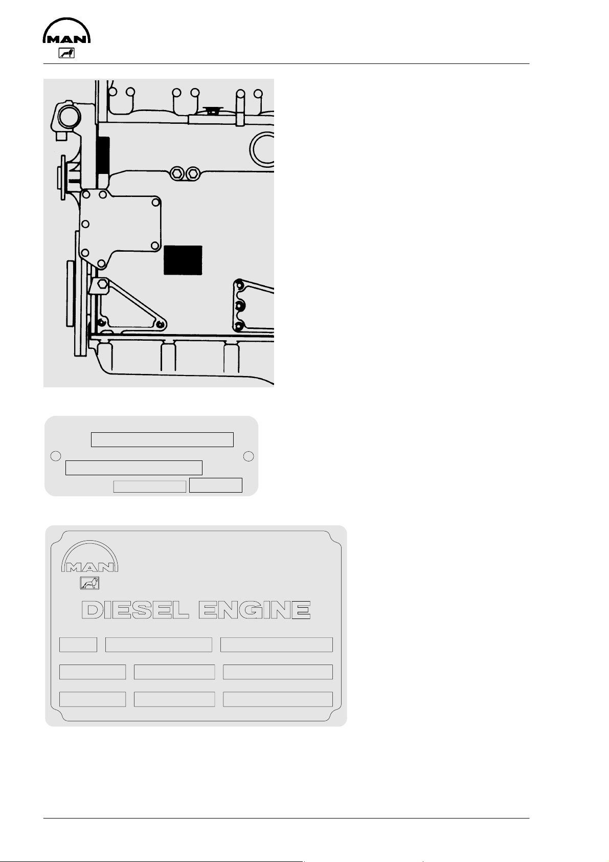
Nameplates
Model
......................................................................
delivered on
......................................................................
installed on
......................................................................
MAN Nutzfahrzeuge Aktiengesellschaft
Typ
Motor-Nr. / Engine No.
NI/II
MAN Nutzfahrzeuge AktiengesellscMAN Nutzfahrzeuge Aktiengesellschaft
Werk Nürnberg Germany
:
Motor–Nr.TypBauj.
In all your correspondence please always
quote engine model, serial number and job
number (Order number).
Enter 14-digit serial number (is used in the
spare parts catalog to distinguish between
spare parts).
Enter 14-digit engine serial
number.
Enter 6-digit job number
(Order number).
Serial NoModelYear
Temp. C
°
Job No Rating kW
Leistung kWWerk–Nr.
Drehz. 1/min
Aufstellhohe m uNNLeistg. PS
:
Speed rpm
:
Altitude mRating BHP
4
–0219
Page 7
Safety regulations
General notes
Handling diesel engines and the necessary resources is no problem when the personnel commissioned with operation and maintenance are trained accordingly
and use their common sense.
This summary is a compilation of the most important regulations. These are broken down
into main sections which contain the information necessary for preventing injury to persons, damage to property and pollution. In addition to these regulations those dictated by
the type of engine and its site are to be observed also.
Important:
If, despite all precautions, an accident occurs, in particular through contact with caustic
acids, fuel penetrating the skin, scalding from hot oil, anti-freeze being splashed in the
eyes etc., consult a doctor immediately.
Regulations designed to prevent accidents with injury to persons
During commissioning, starting and operation
D Before putting the engine into operation for the first time, read the operating instruc-
tions carefully and familiarize yourself with the “critical” points. If you are unsure, ask
your MAN representative.
D For reasons of safety we recommend you attach a notice to the door of the engine
room prohibiting the access of unauthorized persons and that you draw the attention
of the operating personal to the fact that they are responsible for the safety of persons
who enter the engine room.
D The engine must be started and operated only by authorized personnel.
Ensure that the engine cannot be started by unauthorized persons.
D When the engine is running, do not get too close to the rotating parts. Wear close-fit-
ting clothing.
D Do not touch the engine with bare hands when it is warm from operation – risk of
burns.
D Exhaust gases are toxic. Comply with the instructions for the installation of MAN Die-
sel engines which are to be operated in enclosed spaces. Ensure that there is adequate ventilation and air extraction.
D Keep vicinity of engine, ladders and stairways free of oil and grease.
Accidents caused by slipping can have serious consequences.
5
Page 8

Safety regulations
During maintenance and care
D Always carry out maintenance work when the engine is switched off. If the engine has
to be maintained while it is running, e.g. changing the elements of change-over filters,
remember that there is a risk of scalding. Do not get too close to rotating parts.
D Change the oil when the engines is warm from operation.
Caution:
There is a risk of burns and scalding. Do not touch oil drain plugs or oil filters with bare
hands.
D Take into account the amount of oil in the sump. Use a vessel of sufficient size to en-
sure that the oil will not overflow.
D Open the coolant circuit only when the engine has cooled down. If opening while the
engine is still warm is unavoidable, comply with the instructions in the chapter entitled
“Maintenance and Care”.
D Neither tighten up nor open pipes and hoses (lube oil circuit, coolant circuit and any
additional hydraulic oil circuit) during the operation. The fluids which flow out can
cause injury.
D Fuel is inflammable. Do not smoke or use naked lights in its vicinity. The tank must be
filled only when the engine is switched off.
D When using compressed air, e.g. for cleaning the radiator, wear goggles.
D Keep service products (anti-freeze) only in containers which can not be confused with
drinks containers.
D Comply with the manufacturer’s instructions when handling batteries.
Caution:
Accumulator acid is toxic and caustic. Battery gases are explosive.
When carrying out checking, setting and repair work
D Checking, setting and repair work must be carried out by authorized personnel only.
D Use only tools which are in satisfactory condition. Worn open-end wrench slip, which
could lead to injury.
D When the engine is hanging on a crane, no-one must be allowed to stand or pass
under it. Keep lifting gear in good condition.
D When working on parts which contain asbestos, comply with the notes at the end of
this chapter.
6
Page 9

Safety regulations
D When checking injectors do not put your hands under the jet of fuel. Do not inhale ato-
mised fuel.
D When working on the electrical system disconnect the battery earth cable first.
Connect it up again last in order to prevent short circuits.
D When welding comply with the “Instructions for welders”.
Regulations designed to prevent damage to engine and premature wear
Do not demand more from the engine than it is able to supply in its intended application.
Detailed information on this can be found in the sales literature. The injection pump must
not be adjusted without prior written permission of MAN Nürnberg.
If faults occur, find the cause immediately and have it eliminated in order to prevent more
serious damage.
Use only genuine MAN spare parts. MAN will accept no responsibility for damage resulting from the installation of other parts which are supposedly “just as good”.
In addition to the above, note the following points:
D Never let the engine run when dry, i.e. without lube oil or coolant.
D When starting do not use any additional starting aids (e.g. injection with starting pilot).
D Use only MAN-approved service products (fuel, engine oil, anti-freeze and anti-cor-
rosion agent). Pay attention to cleanliness. The Diesel fuel must be free of water. See
“Maintenance and care”.
D Have the engine maintained at the specified intervals.
D Do not switch off the engine immediately when it is warm, but let it run without load for
about 5 minutes so that temperature equalization can take place.
D Never put cold coolant into an overheated engine. See “Maintenance and care”.
D Do not add so much engine oil that the oil level rises above the max. marking on
the dipstick. Do not exceed the maximum permissible tilt of the engine.
Serious damage to the engine may result if these instructions are not adhered to.
D Always ensure that the testing and monitoring equipment (for battery charge, oil pres-
sure, coolant temperature) function satisfactorily.
7
Page 10

Safety regulations
D Comply with instructions for operation of the alternator. See “Commissioning and oper-
ation”.
D Do not let the raw water pump run dry. If there is a risk of frost, drain the pump when
the engine is switched off.
Regulations designed to prevent pollution
Engine oil and filter elements / cartridges, fuel/fuel filter
D Take old oil only to an old oil collection point.
D Take strict precautions to ensure that no oil or Diesel fuel gets into the drains or the
ground.
The drinking water supply could be contaminated.
D Filter elements are classed as dangerous waste and must be treated as such.
Coolant
D Treat undiluted anti-corrosion agent and / or antifreeze as dangerous waste.
D When disposing of spent coolant comply with the regulations of the relevant local auth-
orities.
Notes on safety in handling used engine oil ∗
Prolonged or repeated contact between the skin and any kind of engine oil decreases the
skin. Drying, irritation or inflammation of the skin may therefore occur. Used engine oil
also contains dangerous substances which have caused skin cancer in animal experiments. If the basic rules of hygiene and health and safety at work are observed, health
risks are not to the expected as a result of handling used engine oil.
Health precautions:
D Avoid prolonged or repeated skin contact with used engine oil.
D Protect your skin by means of suitable agents (creams etc.) or wear protective gloves.
D Clean skin which has been in contact with engine oil.
– Wash thoroughly with soap and water. A nailbrush is an effective aid.
– Certain products make it easier to clean your hands.
– Do not use petrol, Diesel fuel, gas oil, thinners or solvents as washing agents.
8
Page 11

Safety regulations
D After washing apply a fatty skin cream to the skin.
D Change oil-soaked clothing and shoes.
D Do not put oily rags into your pockets.
Ensure that used engine oil is disposed of properly
– Engine oil can endanger the water supply –
For this reason do not let engine oil get into the ground, waterways, the drains or the
sewers. Violations are punishable.
Collect and dispose of used engine oil carefully. For information on collection points
please contact the seller, the supplier or the local authorities.
∗ Adapted from “Notes on handling used engine oil”.
Note on parts containing asbestos
D Certain parts of the engine (gaskets) may contain asbes-
tos. Spare parts and, where necessary, their packaging
is marked accordingly (see illustration below).
D When parts that contain asbestos are machined fine as-
bestos dust may be released. To prevent possible damage to health please take appropriate safety precautions
and follow the advice given below:
D Wherever possible work in the open air or in well venti-
lated rooms.
D If possible use hand-operated or slow-running machines,
if necessary with a dust trap. If fast-running machines are
used they ought always to have such a device.
D Wet the material before cutting or drilling it.
a
ACHTUNG
ENTHÄLT
ASBEST
Gesundheits-
gefährdung bei
Einatmen von
ATENÇÃO
CONTEM
AMIANTO
Respirrar po de
amianto é perîgroso
Asbeststaub
Sicherheits-
vorschriften
CONTIENT DE
Langvarig eller gjentatt
påvirkning øker risikoen
Bruk egnet vemeutstyr
para a saúde
Consulte as normas
de segurança
beachten
ATTENTION
L’AMIANTE
Respirer la
poussière d’amiante
est dangereux
pour la santé
Suicre les consignes
de sécurite
INNEHOLDER
ASBEST
Innånding av stov
fra dette materialet
kan forårske kreft
VAROITUS
SISÄLTÄÄ
ASBESTIA
Asbestipölyn
hengittäminen on
terveydelie
vaarallistta
Noudattakaa
turvaohjeita
ARTIKELN
INNEHÅLLER
ASBEST
Dammet är
farligt vid inandning
Innehåller
Asbest
WARNING
CONTAINS
ASBESTOS
Breathing asbestos
dust is dangerous
to health Follow
safety Instructions
VOORZICHTIG
BEVAT
ASBEST
Het inademen van
asbeststof
is schadelijk voor
de gezondheit
Houdt u aan de
veiligheids-
voorschriften
ATTENZIONE
CONTIENE
AMIANTO
Resirare polvere di
amiento é
pericoloso
per la salute
Seguire le norme
di sicurezza
PRECAUCIÓN
:CONTIENE
AMIANTO
Evitese ta
generación
de polvo
D Wet the dust, put it into a tightly closing container and have it disposed of as danger-
ous waste.
9
Page 12
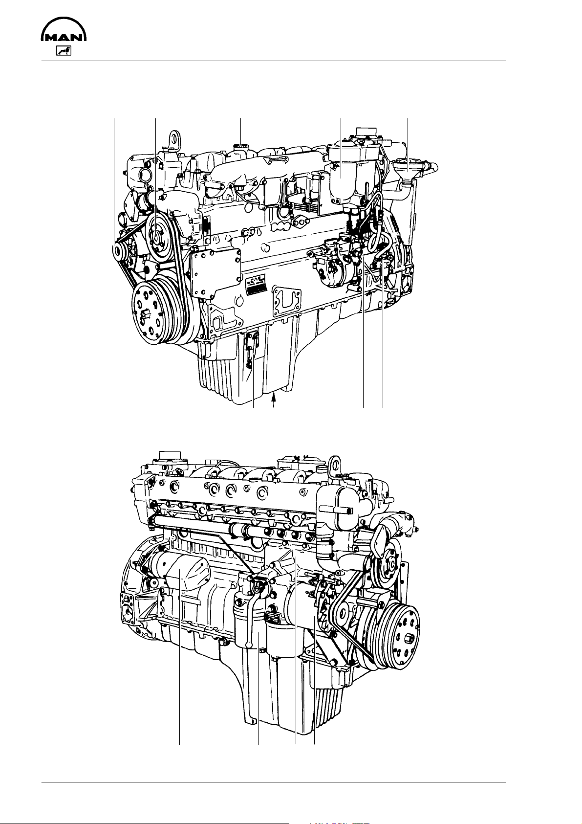
Engine views D 2866 E
12 3 4 5
Technical information
7689
10
10111213
Page 13

Technical information
1 Tensioning pulley
2 Water pump
3 Oil filler neck
4 Tandem fuel filter
5 Oil separator valve for crankcase breather
6 Fuel lift pump with prestrainer
7 Injection pump
8 Oil drain plug
9 Oil dipstick
10 Alternator
11 Oil cooler
12 Oil filter
13 Starter motor
11
Page 14
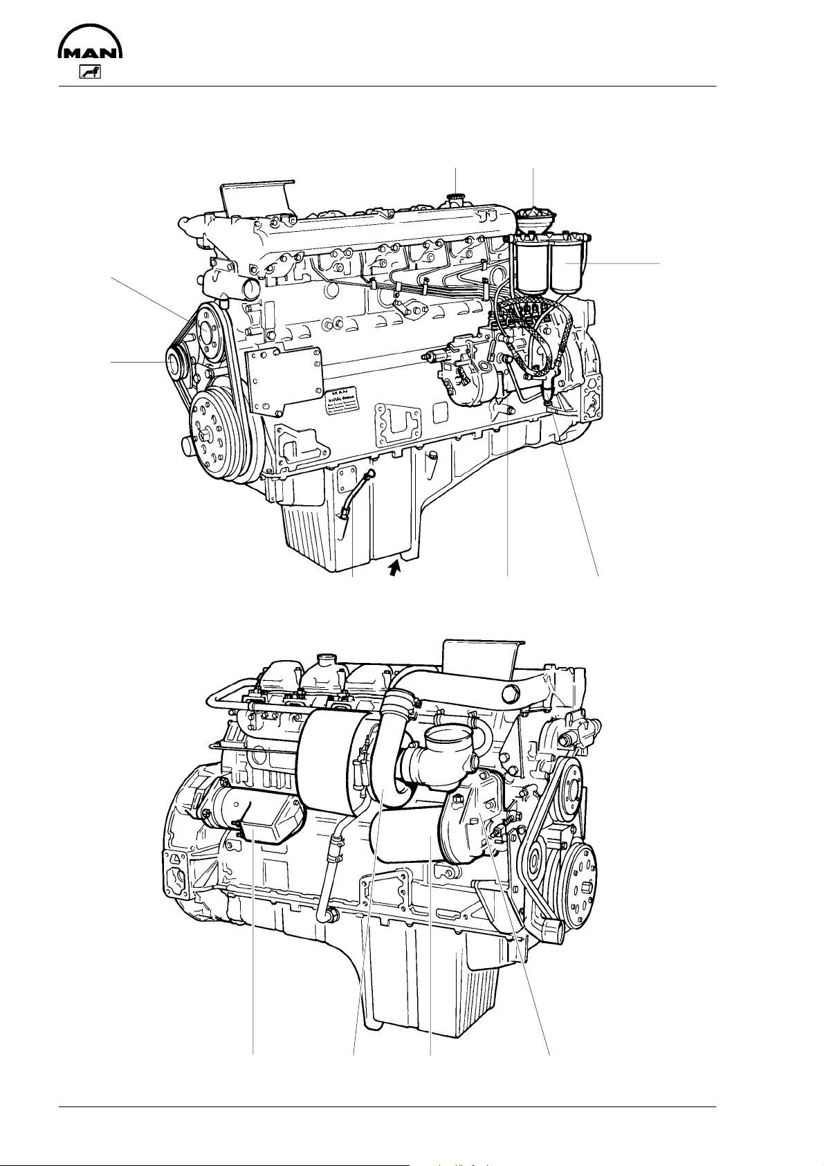
Engine views D 2866 TE
Technical information
3
2
1
4
5
6789
12
10111213
Page 15

Technical information
1 Tensioning pulley
2 Water pump
3 Oil filler neck
4 Oil separator valve for crankcase breather
5 Tandem fuel filter
6 Fuel lift pump with prestrainer
7 Injection pump
8 Oil drain plug
9 Oil dipstick
10 Oil cooler
11 Oil filter
12 Turbocharger
13 Starter motor
13
Page 16
Technical information
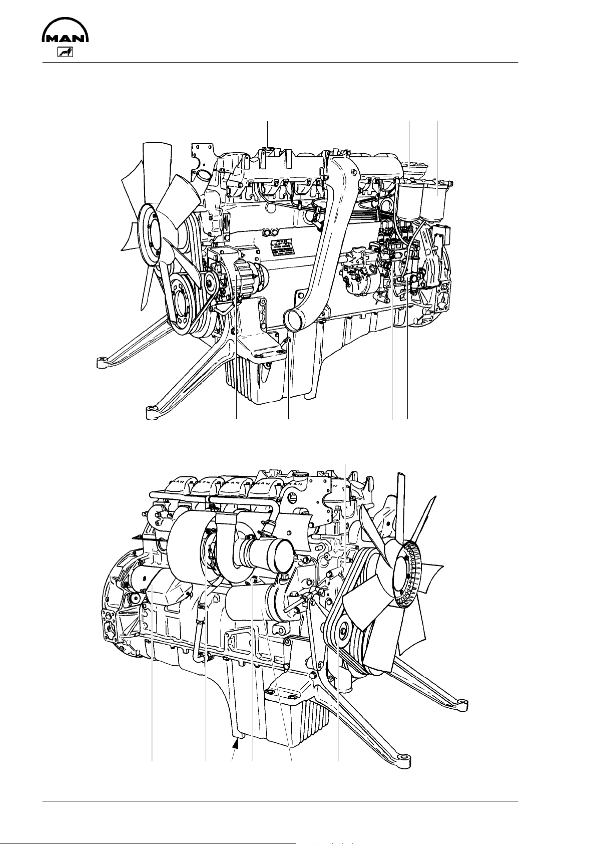
Engine views D 2866 LE, LXE
123
4567
8
14
91011121314
Page 17

Technical information
1 Oil filler neck
2 Oil separator valve for crankcase breather
3 Tandem fuel filter
4 Fuel lift pump with prestrainer
5 Injection pump
6 Oil dipstick
7 Alternator
8 Water pump
9 Tensioning pulley
10 Oil filter
11 Water drain plug
12 Oil drain plug
13 Turbocharger
14 Starter motor
15
Page 18

Technical information
Engines
The engines D 2866 E / TE / LE / LXE are in-line vertical liquid-cooled 6-cylinder fourstroke Diesel engines with direct injection. D 2866 E is a naturally aspirated engine.
D 2866 TE is turbocharged, and D 2866 LE / LXE are turbocharged and intercooled.
Engine block
The cylinder block is a single piece of alloy cast iron. To increase its stiffness, it is extended to a level below the crankshaft centre line. The engine has replaceable wet cylinder liners and individual cylinder heads with shrunk-in valve seat rings and replaceable
valve guides.
Piston / Conrod / Crank assembly
The forged crankshaft has screwed-on counterweights. Radial seals with replaceable
wearing rings on crankshaft and flywheel are provided to seal the crankcase penetrations.
The connecting rods are die-forged, diagonally split and can be removed through the top
of the cylinders together with the pistons. Crankshaft and connecting rods run in steelbacked lead bronze ready-to-fit type bearings.
16
Page 19

Technical information
Engine timing
Camshaft, oil pump and injection pump are driven by a gear train arranged at the flywheel end.
5
6
4
1
2
1 Crankshaft gear 4 Camshaft drive gear
2 Oil pump drive gear 5 Idler gear
3 Oil pump impeller gears 6 Injection pump drive gear
The crankshaft gear and camshaft gear are match-marked by “1” or “D”.
Valves
The overhead valves are actuated via chilled cast iron tappets, push rods and rocker
arms from the camshaft.
3
17
Page 20
Technical information
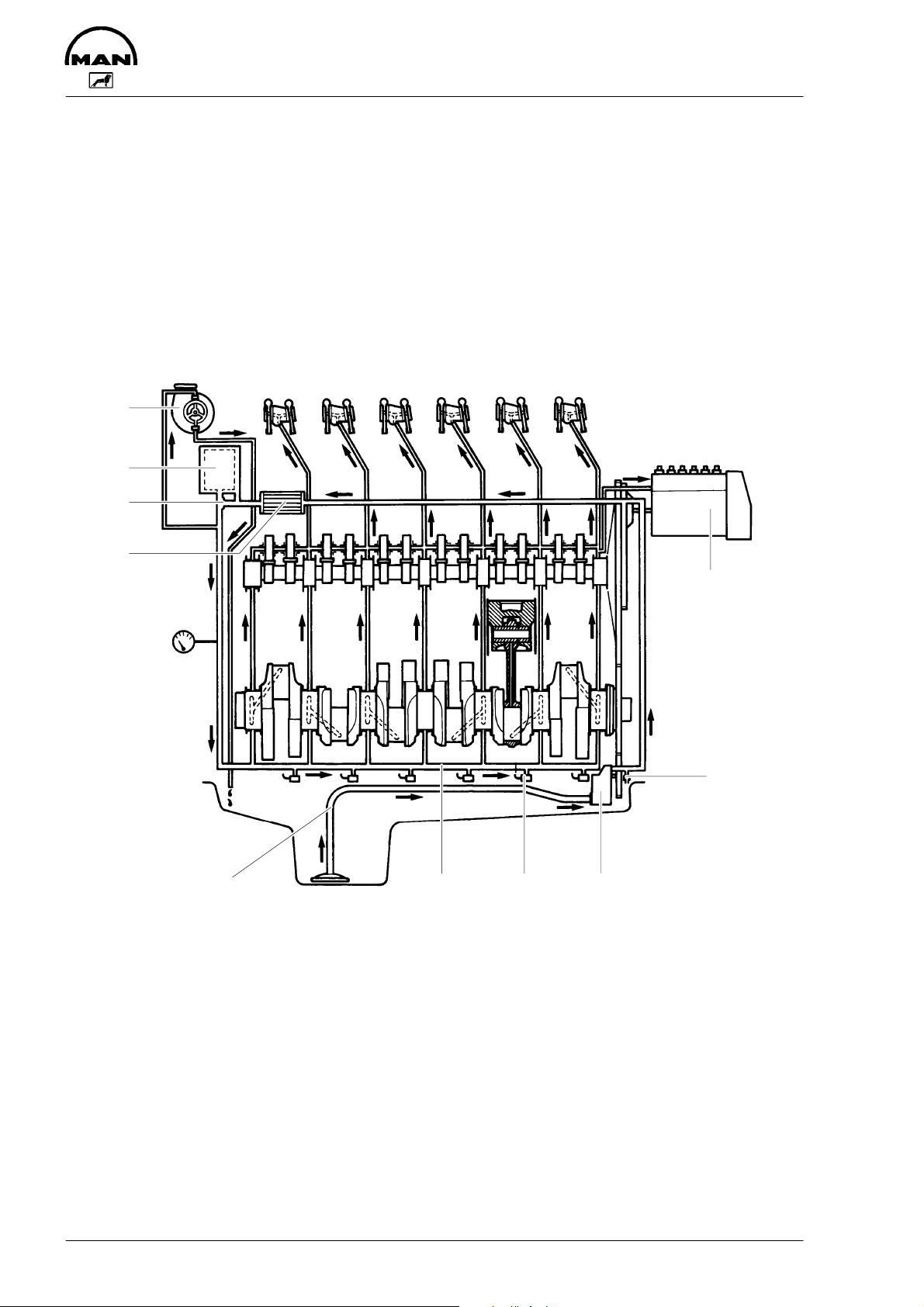
Engine lubrication
The engine is equipped with force-feed lubrication.
The pressure is produced by a gear pump whose drive gear is in direct mesh with the
crankshaft gear at the flywheel end.
The oil pump draws the oil from the oil sump and delivers it through the oil cooler and oil
filter to the main distributor gallery and from there to the main bearings, big-end bearings
and camshaft bearings as well as to the small-end bearings and the rocker arms.
8
7
6
9
10
5
1234
1 Oil suction pipe 7 Oil filter
2 Main oil galleries 8 Turbocharger
3 Jets for piston cooling and cam lubrication (D 2866 TE / LE / LXE only)
4 Oil pump 9 Oil cooler
5 Oil relief valve 10 Injection pump
6 Bypass valve
18
Page 21

Technical information
The injection pump and the turbocharger are also connected to the engine lubricating
system.
The cylinder walls and timing gears are splash-lubricated.
Each cylinder has an oil jet provided for cooling the underside of the pistons.
The lube oil is cleaned in a full-flow oil filter.
Depending on the agreed extent of delivery and the design of the engine, the lube oil circuit can be equipped with oil pressure monitors (advance warning and cut-off function)
which shut the engine down in the event of a sudden loss of pressure.
Oil cooler
An oil cooler is provided between the oil filter and the crankcase. This cooler is of the flat
tube type with turbulence inserts and operated by the coolant.
19
Page 22

Technical information
Fuel system
The fuel is delivered by the fuel lift pump via the fuel filter to the injection pump and from
there to the injectors.
The fuel is sprayed into the cylinder through four-hole nozzles fitted in screw-fit injectors
in the cylinder heads.
Excessive fuel delivered and leak fuel from the injectors flow through the return pipe back
to the tank. A strainer and a hand pump are arranged ahead of the fuel lift pump.
45 48 67
10
1 Fuel tank
2 Fuel strainer
3 Fuel lift pump
4 Parallel fuel filter
5 Bleeder screw
6 Injection pump
7 Overflow valve
8 Injection nozzles
9 Suction line
10 Return line
3
2
9
1
Injection pump
The in-line injection pump is driven via gears from the crankshaft. It is connected to the
force-feed lubricating system of the engine and consequently maintenance-free.
The centrifugal governor flange-mounted on the pump casing is a variable range governor designed to keep the speed set by the control lever constant under conditions of
varying load.
The governor of the turbocharged engines has a full load stop controlled by the chargeair pressure and is designed to decrease the full load fuel quantity in the low speed
range from a certain (adjustable) charge-air pressure onwards.
20
Page 23

Technical information
Fuel filters
Before entering the suction chamber of the injection pump, the fuel is cleaned in a twostage, parallel or changeover filter.
Turbocharger (D 2866 TE, LE, LXE)
The exhaust gases of the engine are passed through the turbine rotor of the turbocharger. Air impeller mounted on the same shaft draws in fresh air and delivers it at a higher
pressure to the cylinders.
The turbocharger is air-cooled or liquid-cooled. Lubrication of the main bearing is by oil
under pressure from the engine lubricating system.
1
D
A
3
E
1 Compressor casing A Air inlet
2 Turbine casing B Gas outlet
3 Compressor wheel C Gas inlet
4 Turbine rotor D Oil inlet
E Oil return
2
4
B
C
21
Page 24

Technical information
Intercooler (D 2866 LE, LXE)
Before entering the cylinders the combustion air compressed in the turbocharger is
passed through a heat exchanger (intercooler).
Heat removal in the cooler is either by air (air-to-air intercooler) or, in case of the marine
application, by means of seawater (air-to-water intercooler) delivered by the raw water
pump.
It is important to provide a seawater filter ahead of the air-to-water intercooler.
In the case of extended standstills, cleaned seawater may be left in the intercooler, but
dirty water (brackish water) must definitely be discharged.
The seawater-operated intercooler must be regularly cleaned as required in order to
maintain its full cooling efficiency. If the engine output is found to drop, the reason may
be in a fouled-up intercooler. The intercooler has to be removed from the engine for
cleaning.
Cooling
The engine has a liquid-cooling system.
The water pump is a maintenance-free impeller pump driven by V-belts from the crankshaft pulley.
Depending on the agreed extent of delivery and the design of the engine, the coolant circuit can be equipped with temperature and level monitors which, in the event of overheating, will trigger an advance warning system or, in the event of loss of coolant, shut
the engine down.
Air cleaner
Air cleaner is mounted on the engine to purify the air for combustion.
The intervals at which the air cleaner requires servicing depend on the specific operating
conditions encountered. Clogged air filters may cause black smoke and reduce power.
A check should be made from time to time to see that the fastening elements securing
the air cleaner to the intake manifold seal the connection tightly. Any ingress of unfiltered
air is liable to cause a high rate of cylinder and piston wear.
22
Page 25

Technical information
Electrical equipment
Alternator
The alternator is fitted with integral silicon rectifiers.
A transistorized regulator mounted on the alternator limits the alternator voltage. The alternator should not be operated except with the regulator and battery connected in circuit
to avoid damage to the rectifier and regulator.
The alternator is maintenance-free. Nevertheless, it must be protected against dust and,
above all, against moisture.
Operate the alternator according to the instructions given in the chapter “Commissioning and operation”.
Starter motor
The sliding-gear starter motor is flanged to the rear of the flywheel housing on the righthand side.
As part of every engine overhaul, the starter pinion and ring gear should be cleaned with
a brush dipped in fuel and then a coat of grease should be applied again.
Always protect starter motor against moisture.
Warning:
Always disconnect the battery earth cable before starting work on the electrical system. Connect up the earth cable last, as there is otherwise a risk of short-circuits.
23
Page 26

Commissioning and operation
Preparations
At the time of initial commissioning of a
new or overhauled engine make sure to
have observed the “Technical Information
for the installation of MAN Diesel engines”.
1
1 Oil filler neck on valve cover
Before daily starting the engine, check
fuel level, coolant level and engine oil
level and replenish, if necessary.
D Thereafter fill up to maximum oil sump
capacity, wait about 1/2 hour and mark
maximum oil level visible on dipstick
D After refilling with oil, rotate the engine
with the starter and move the shutdown lever to “stop” at the same time
until the oil pressure warning light goes
out and the oil pressure gauge shows a
pressure. Then start the engine and
allow it to run at medium speed for a
few minutes. Check oil pressure and
tightness of system. Then shut down
the engine. After about 20 minutes,
check the oil level. The oil level should
now be at the upper notch of the dipstick, but not higher.
Add any necessary oil to the upper dipstick mark.
Caution:
Do not add so much engine oil that the
oil level rises above the max. marking
on the dipstick. Overfilling will result in
damage to the engine.
The notches in the dipstick indicate the
highest and lowest permissible oil levels.
Marking the dipstick
As a rule oil dipsticks of marine propulsion
engines are not marked by the manufacturer since the final installed position is
unknown. Therefore, they should be
marked after engine installation.
Proceed as follows:
D Fill with minimum oil quantity recom-
mended for the respective engine type.
After this initial filling wait about
1/2 hour until the entire oil has collected in the oil sump
D Pull out dipstick and mark minimum oil
level visible on dipstick
The oil required in the sump is specified in
the “Technical Data” at the end of these
Instructions.
Note:
The oil required to fill the oil filters and
pipes depends upon the engine equipment and use and must be determined
individually at the time of initial commissioning (Make a note of the determined quantity).
Ensure outmost cleanliness when handling fuels, lubricants and coolants.
Use only approved fuels, lubricants
etc. (see brochure “Fuels, lubricants
etc.”). Otherwise the manufacturer’s
warranty will become null and void.
24
Page 27

Commissioning and operation
Raw water pump
Do not let raw water pump run dry.
Make sure that all valves / cocks in the
raw water circuit are open.
If there is a risk of frost, drain the raw
water pump.
Starting
Insert key in starting lock.
Press starter button, moving control lever
against stop “maximum engine speed”.
Do not operate starter for longer than
10 seconds at a time.
After ignition of the engine, release the
starter button and adjust control lever for
desired speed.
If engine fails to start, release the key,
wait about 30 seconds, then operate
starter again.
Running in
It is recommended that new or overhauled
engines should not be operated at a load
higher than about 75% maximum load
during the first few hours of operation. Initial run-in should be at varying speeds.
After this initial run-in, the engine should
be brought up to full output gradually.
During operation
Do not overload the engine. Do not exceed the maximum permissible engine
tilt. If faults occur, find their cause immediately and have them eliminated in
order to prevent more serious damage!
During operation the oil pressure in the
engine lubrication system must be monitored. If the monitoring devices register a
drop in the lube oil pressure, switch off the
engine immediately.
Avoid running the cold engine for any
length of time since in any internal combustion engine this is liable to cause increased wear due to corrosion. Prolonged
idling is harmful to the environment.
Note:
On initial start of an overhauled engine
or after long periods without use, press
shut-down lever in “stop” position and
operate starter motor for a few seconds (max. 10) until oil pressure is
indicated. Only then the engine should
be started in the normal way.
The coolant temperature should be
approx. 80 to 85°C.
The charge warning light of the alternator
should go out when the engine is running.
25
Page 28

Commissioning and operation
Alternator
In order to avoid damage to the alternator,
observe the following instructions:
While the engine is running
D Do not de-energize the main battery
switch!
D Do not disconnect the battery or pole
terminals or the cables!
D If, durig operation, the battery charge
lamp suddenly lights up, stop the engine immediately and remedy the fault
in the electrical system!
D Do not run the engine unless the bat-
tery charge control is in satisfactory
order!
D Do not short-circuit the connections of
the alternator with those of the regulator or said connections with ground, not
even by briefly bringing the connections
into contact!
D Do not operate the alternator without
battery connection!
Shutting down
Disengage the gearbox clutch and move
the shut-down lever to “stop”. After the engine has been running at a high load
level, do not shut it down immediately but
allow it to idle about 5 minutes so that
temperatures may equalize.
Remove key from starting lock.
Caution:
Ensure that the engine can not be
started by unauthorized persons.
Temporary decommissioning of engines
Temporary anti-corrosion protection according to MAN works norm M 3069 is required for engines which are to be put out
of service for fairly long periods.
The works standard can be obtained from
our After-Sales Service department in Nuremberg.
26
Page 29

Maintenance and care
Engine lubrication
Oil level
Check the oil level in the engine sump
daily with a dipstick. The level should be
between the two notches cut into the dipstick and should never be allowed to drop
below the lower notch.
Caution:
Do not add so much engine oil that the
oil level rises above the max. marking
on the dipstick. Overfilling will result in
damage to the engine.
The oil level should be checked with the
engine horizontal and only after it has
been shut down for about 20 minutes.
Oil drainage
With the engine at operating temperature,
remove the oil drain plugs on the oil sump
and the oil filter bowl and allow the old oil
to drain off completely. Use a vessel of
sufficient size to ensure that the oil does
not overflow. Refit the oil drain plugs with
new gaskets.
Caution:
The oil is hot- risk of scalding. Do not
touch the oil drain plug with bare fingers. Oil is an environmental hazard.
Handle it with care!
1
1 Oil filler neck on valve cover
After refilling with oil, rotate the engine
with the starter and move the shut-down
lever to “stop” at the same time until the
oil pressure warning light goes out and
the oil pressure gauge shows a pressure.
Then start the engine and allow it to run at
medium speed for a few minutes. Check
oil pressure and tightness of system.
Then shut down the engine. After about
20 minutes, check the oil level. The oil
level should now be at the upper notch of
the dipstick, but not higher.
Add any necessary oil to the upper dipstick mark.
Note:
Refer to maintenance chart for compulsory oil change intervals and oil
quality for D 2866 TE engines having
higher ratings.
Lubricating oil filter
Refilling with oil
Refill with fresh engine oil at the oil filler
neck.
Cleaning of the lubricating oil is effected in
a full-flow oil filter with paper cartridges. A
bypass valve ensures continuity of oil supply if the filter elements should be
clogged.
After draining off the oil, release tie screw.
Remove filter bowl. Renew filter cartridge.
Thoroughly clean all other parts in cleaning fluid. Use new gaskets for re-assembly
27
Page 30

Maintenance and care
2 3
1 4 5
1 Oil drain plug
2 Oil filter bowl
3 Tie screw
4 Filter cartridge
5 Gasket
Observe positions of selector lever!
Continuous operation
(both filter halves
in operation)
Right-hand filter
cut out
Left-hand filter
cut out
Caution:
Do not leave selector lever in any intermediate position because this
would be liable to interfere with oil
supply.
5
4
2
1
3
1 Oil drain plug
2 Oil filter bowl
3 Tie screw
4 Filter cartridge
5 Gasket
Renewal of filter cartridges
D Allow the filter content to run off along
drain plugs. Hold a suitable vessel
under hole
Caution:
Oil is hot and under pressure!
D After releasing the clamping bolts re-
move filter bowls
D Renew filter cartridges. Thoroughly
clean all other parts in cleaning fluid
(do not allow cleaning fluid to enter the
oil circuit)
D Use new gaskets for reassembly of fil-
ter bowls
Note:
To prevent the seal from twisting hold
the filter bowl firmly when tightening the
tensioning screw
Every time an oil change is made, the two
oil filter cartridges should be renewed!
A changeover-type oil filter, the filter elements of which can be replaced even
during operation, can be fitted on request.
During continuous operation position the
selector lever that both filter halves are in
operation.
Caution:
Used oil filters are classed as dangerous waste and must be disposed of
accordingly.
28
Page 31

Maintenance and care
Fuel system
Fuel
If Diesel fuel which contains moisture is
used the injection system and the cylinder
liners / pistons will be damaged. This can
be prevented to same extent by filling the
tank as soon as the engine is switched off
while the fuel tank is still warm (formation
of condensation is prevented). Drain
moisture from storage tanks regularly. Installation of a water trap upstream of the
fuel filter is also advisable. Do not use any
additives to improve flow properties in
winter.
Injection pump
Fuel lift pump
The fuel lift pump is operated by the injection pump camshaft via the roller tappet.
Strainer
3
1
2
No alterations must be made to the injection pump. If the lead seal is damaged the
warranty on the engine will become null
and avoid.
Faults
We urgently recommend that you have
faults in the injection pump rectified only in
an authorised specialist workshop.
Bleeding the fuel system
Bleeding the fuel filters is by releasing the
bleed screws and operating the manual
primer (fit new seals).
The suction chamber of the injection
pump is continuously bled via the relief
valve during operation. If the suction
chamber is completely empty, e.g., when
fitting a new pump, filling and bleeding it is
by actuating the manual primer.
1 Fuel strainer
2 Filtering screen
3 Filter housing
After every 200 hours of operation the fuel
strainer connected upstream of the fuel lift
pump should be cleaned.
Fuel filter
After every 1000 hours of operation – or
earlier if loss of engine power indicates
clogging – the filter elements should be
renewed.
29
Page 32

Maintenance and care
Two-stage fuel filter
(replaced by parallel fuel filter)
In two filter housings connected in series
the fuel first passes through a felt tube element and then through a paper element.
5
3
1 Felt tube element (primary filter)
2 Paper element (secondary filter)
3 Vent plugs
4 Filler plug
5 Clamping screws
Replacement of filter elements
D Remove clamping bolts
D Take off filter bowls
D Take out filter elements
D Wash out filter bowls
D Install new filter cartridges
D Refit filter bowls using new gaskets
D Open vent plug for primary filter (felt
tube element). Fit new seals
D Operate manual fuel lift pump until fuel
is emitted without any bubbles
D Close vent plug on primary filter
D Bleed secondary filter in the same
manner
4
1
2
Parallel fuel filter with filter cartridges
(replaced by parallel filter with interchangeable filter)
The fuel passes through two filter elements connected in parallel.
2
3
1
1 Filter elements
2 Vent plugs
3 Filler plug
4 Clamping screws
Replacement of filter elements
D Remove clamping bolts
D Take off filter bowls
D Take out filter elements
D Wash out filter bowls
D Install new filter cartridges
D Refit filter bowls using new gaskets
D Open vent plug (fit new seals)
D Operate manual fuel lift pump until fuel
is emitted without any bubbles
D Close vent plug
4
1
30
Page 33

Maintenance and care
Parallel fuel filter with interchangeable
filter
The fuel flows through two parallel filters.
3
2
3
1
4
1 Filter cartridge
2 Screw plug
3 Bleed screw
4 Moisture drain plugs
Draining moisture:
Unscrew drain plugs at every oil change
until moisture has been discharged and
clean fuel flows out.
Replacement of filter elements:
After every 1000 hours of operation – or
earlier if loss of engine power indicates
clogging – the filter elements should be
renewed.
Caution:
Used fuel filters are classed as dangerous waste and must be disposed of
accordingly.
Change-over fuel filter with filter cartridges
(replaced by change-over fuel filter with
interchangeable filter)
Where the changeover-type filter is installed, the servicing procedure is for the
filter side requiring to be shut off with the
engine running. During continuous operation, the selector lever should be placed
in a position where both filter halves are in
operation.
9
8
1
11
7
3
5
2
4
10
6
12
1 Changeover type filter
2 Collecting vessel
3 Cover for collecting vessel
4 O-ring
5 Gasket
6 Fixing bolts for collecting vessel
7 Screw nut
8 Filler plug
9 Vent plug
10 Fixing nut
11 Sludge drain plug
(socket head width across flats 5)
12 Selector lever
31
Page 34

Maintenance and care
Caution:
Do not leave selector lever in any intermediate position because this
would be liable to interfere with fuel
supply. If in doubt stop the engine to
change the fuel filter.
Continuous operation
(both filter halves
in operation)
Right-hand filter
cut out
Left-hand filter
cut out
Change-over fuel filter with interchangeable filter
2
3
1
1 Filter cartridge
2 Bleed screw
3 Selector lever
To replace filter element
D Move selector lever to position where
filter side to be cleaned is cut out
D Slacken vent plug 1 or 2 turns (fit new
seals)
D Allow filter to drain through sludge drain
plug
D Take off filter cover on slackening fixing
nut
D Withdraw filter element and flush filter
chamber with clean fuel
D Install new element
D Fit filter cover using new gasket
D Fill filter bowl through filler opening with
fuel. Close vent plug
D Position selector lever so that both
filters are in circuit
Replacement of filter elements:
After every 1000 hours of operation – or
earlier if loss of engine power indicates
clogging – the filter elements should be
renewed.
Caution:
Used fuel filters are classed as dangerous waste and must be disposed of
accordingly.
32
Page 35

Maintenance and care
Injector maintenance
(by authorized specialist personnel)
2
4
5
1
6
7
8
9
1 Nozzle holder
2 Union screw
3 Washer
4 Compression spring
5 Thrust pin
6 Intermediate disc
7 Injection nozzle
8 Nozzle nut
9 Gasket
Removal, dismantling and cleaning
Unscrew delivery pipe at nozzle holder
and at the injection pump.
3
Remove leak-off pipe.
Release union screw of nozzle holder with
special wrench.
Remove nozzle holder with gasket from
the cylinder head.
Note for cleaning nozzles with Bosch
cleaning set KDEP 2900
Clean nozzle body externally from soot
and carbon. When cleaning several
nozzles at the same time, make sure
nozzle bodies and needles are not mixed
up. Visually inspect needle and body.
Cleaning is useless if the seat of the
needle is indented or the pintle is damaged and the nozzle should be replaced.
Clean annular groove with scraper over
full circumference. Wash out dislodged
carbon deposits and dirt.
The injectors are designed to spray the
fuel delivered by the injection pump directly into the spherical combustion
chamber in the piston crown.
The injector consists of the nozzle and the
nozzle holder.
A copper gasket fitted to the injector ensures gas-tight seating and good heat dissipation.
The opening pressure of the nozzle is adjusted by means of shims at the compression spring.
Scrape needle seat with cleaning cutter.
Dip cutter in test oil before use. The cutter
can also be clamped in a lathe.
Polish needle seat with wooden cleaning
tool, preferably by chucking the needle in
a lathe at the pintle end.
Clean the spray holes of hole nozzles
using the cleaner KDEP 2900/2 by chucking a cleaning needle of suitable diameter
in the collet. If the carbon deposits in the
spray holes cannot be removed by rotating and pressing, have the needle project
only slightly from the collet and drive out
the carbon by lightly tapping on the tool.
33
Page 36

Maintenance and care
Before reassembly thoroughly wash
nozzle body and needle in clean test oil.
Hold the needle at the pintle end only; to
avoid corrosion do not touch the lapped
surfaces of the needle with your fingers.
Thoroughly clean all other parts of the
nozzle holder with clean fuel.
Check nozzle discharge pressure in
nozzle tester.
The edge-type filter should not be pressed
into the nozzle holder by approx. 5 mm.
If this depth is exceeded the injector must
be replaced.
Caution:
Do not hold your hands under the fuel
jet, as there is a risk of injury. Do not
inhale the atomised fuel. If possible
work under an extraction system.
Installation
Clean seat in cylinder head.
Insert nozzle holder with new gasket.
Tighten union nut with 120 Nm.
Install injection lines free of constraint.
Install leak fuel lines.
Caution:
The injection lines are designed for
high operating pressures and should
thus be handled with particular care.
1
1 Edge-type filter
Check nozzle discharge pressure in
nozzle tester. Adjust the discharge pressure by inserting shims of suitable thickness under the compression spring.
D When mounting the pipes to the engine
take care of good fitness
D Do not bend pipes to permanent de-
formation (not for replacing the nozzles
either)
D Do not mount any heavily bent pipes
D Avoid bending the pipes at the ends by
more than 2 to 3 degrees
D In case of faults in the injection system
which might have resulted in excessive
operating pressures, not only the failed
part but also the injection line has to be
replaced
34
Page 37

Maintenance and care
Cooling
Fill the cooling system of the engine with a
mixture of drinkable tap water and antifreeze agent on ethylene glycole basis or
anti-corrosion agent.
See Publication “Fuels, Lubricants and
Coolants for MAN Diesel Engines”.
Filling-in of coolant
(only when engine has cooled down)
D Fill in the coolant slowly
D Make sure that all air can escape from
the cooling system
D Run the engine briefly and then check
coolant level once more
If, in an exceptional case, the coolant
level has to be checked in an engine that
has reached operating temperature, first
carefully turn the cap (large cap) with
safety valve to the first stop, let off pressure, then open carefully.
Draining of coolant
Drain plug in oil cooler housing cover (for
engines with liquid-cooled turbocharger)
Drain coolant as follows when cooling system has cooled down:
D Remove cover from filler neck of surge
tank
D Remove drain plug in crankcase, oil
cooler housing and exhaust manifold
Coolant must be added at the filler
neck only. Do not put cold coolant into an
engine which is warm from operation.
Ensure that the ratio of water to antifreeze is correct. Find the cause of the
loss of coolant and have it eliminated.
Warning:
If the cap with the working valves is
opened, there is the risk that it will not
close tightly again afterwards. The excess pressure required in the system
will then no longer build up. Premature
boiling occurs and coolant is lost. To
prevent damage to the engine open
this cap only in exceptional circumstances and fit a new one as soon as
possible.
Drain plug in oil cooler housing
35
Page 38

Maintenance and care
1
2
1 Working valve
2 Filler cap
Improper mixing of anti-freeze and corrosion inhibitors may lead to lime and corrosion deposits in the engine cooling system which can jeopardize cooling
efficiency.
In such cases it is necessary to clean the
cooling system at suitable intervals.
D Let the mixture work for 5 minutes
D Hose down the radiator with a straight
jet of tap water directly from the front.
In cases of stubborn dirt deposits remove the radiator and hose it down directly from behind. Do not use highpressure cleaners (steam sprayers may
be used)
Henkel P3-begesol contains no toxic or
corrosive substances and, if handled
properly, may be used without hesitation.
Cleaning the inside of the cooling system
(by authorized specialist personnel)
Investigations have shown that in many
cases the poor condition of the coolant
and / or the cooling system accounts for
damage to the water pump mechanical
seal. The poor condition of the cooling
system is normally due to use of unsuitable or no anti-freezing agents and corrosion inhibitor or defect, not early enough
replaced covers for filler neck and working
valves.
Cleaning the outside of the radiator
(wear goggles)
Extreme dirt deposits can clog the honeycombs so that the remaining surface no
longer ensures sufficient cooling. In such
cases, the insects, dust etc. should be removed from the honeycomb system of the
radiator block and the radiator itself then
cleaned with the cleansing agent HENKEL
P3-begesol. This cleansing agent is available from MAN in 10-kg cans under Part
No. 09.21002-0164.
Procedure:
D Mix P3-begesol with water, ratio 1:1
D Using a spray gun, spray the mixture in
as straight a jet as possible directly into
the radiator fins
If twice in a short time the water pump of
an engine develops leakes or the coolant
is heavily contaminated (dull, brown,
mechanically contaminated, grey or black
signs of a leakage on the water pump
casing, after the defect on the oil cooler)
clean the cooling system prior to removing that water pump as follows:
a) Drain coolant
b) Open thermostats positively (use short-
circuit inserts), so that the entire coolant circuit is flushed in the cleaning
operation
c) Fill coolant circuit with a mixture of hot
water (min. 50°C) and Henkel P 3 neutrasel 5265 detergent (1.5% by volume)
(-5266, -5225, Kluthe Hakopur 316),
see Publication “Fuels, Lubricants ...”
36
Page 39

Maintenance and care
d) Warm up engine under load. After a
temperature of 60°C is reached, run
engine for a further 15 minutes
e) Drain cleaning fluid
f) Repeat steps c) and d)
g) Flush cooling system. To this effect
h) Replace drain plug by drain plug with a
bore of 8 mm dia
i) Fill cooling system with hot water
k) Run engine at idle for 30 minutes. At
the same time continuously replenish
the water leaking from the bore in drain
plug by adding fresh water
Repair water pump only now. Thereafter,
fill the cooling system with approved cooling fluid. See Publication “Fuels, Lubricants ...”.
Note:
Only sediments and suspended particles can be removed by this cleaning
method. If corrosion and lime deposits
are found, proceed according to the
following section:
D Drain the pickling fluid, fill the system
with tap water, and run the engine at
idle for 5 minutes to flush out all fluid;
then drain the water
D Fill the system with a 1% soda solution.
Drain the soda solution after running
the engine at idle for 5 minutes, and
flush with tap water until the discharging water is clear
D Fill cooling circuit with a mixture of po-
table tap water and anti-freeze with at
least 40% by volume, refer to Publication “Fuels, Lubricants ...”
Note:
Older radiators may develop leaks
when such deposits are removed. The
surge tank should be filled only up to
the bottom edge as otherwise foaming
will cause the pickling fluid to spill over.
Cleaning the inside of tube bundles of
raw water heat exchangers
(by authorized specialist personnel)
Removal of lime deposits in the cooling system
(by authorized specialist personnel)
Procedure:
D Drain the coolant
D Fill the system with undiluted original
pickling fluid (Lithsolventsäure or en-
gine pickling fluid RB-06), see sources
of supply
D Let the engine run (also in normal oper-
ation) for approx. 8 hours with this fill-
ing in the cooling circuit
D Drain the pickling fluid and thoroughly
flush the system with tap water
D If necessary, refill the circuit again with
fresh pickling fluid and pickle the en-
gine for another 8 hours
Deposits building up inside the tube
bundle of the water-to-water heat exchanger can reduce the flow cross-section
of the individual tubes to the point where a
decrease in engine cooling occurs. This
condition will automatically lead to overheating of the engine with all of its accompanying effects. For this reason, it is recommendable to clean the tube bundle of
the water-to-water heat exchanger at the
first sign of high engine coolant.
Procedure:
D Remove and dismantle the heat ex-
changer (integrated in the coolant
surge tank)
D Place the removed tube bundle in a
suitable container made of plastic, such
as PE, PP, PVC, GFK
37
Page 40

Maintenance and care
D Fill the container with undiluted original
pickling fluid at room temperature (Lithsolventsäure or engine pickling fluid
RB-06) until the tube bundle is completely immersed
D Allow the pickling fluid to work approx.
10 hours. If this time is not sufficient,
continue the pickling process for up to
5 hours
D Pickling can be shortened by heating
up the fluid (max 50°C) and by occasionally moving the tube bundle
D After pickling thoroughly flush the
bundle with tap water and reinstall in
the heat exchanger
D Use new gaskets (O-seals)
D Mount the heat exchanger on the en-
gine and check for tightness
Note:
The variety of dirt deposits may also
create problems for the method of
pickling described above. In such
cases, we ask you to first of all submit
a specimen of the deposit for further
examination.
Damaged tube bundles may develop
leaks when dirt deposits are removed.
Filler caps and working valves of cooling system
The rubber gaskets of the filler caps and
working valves (negative pressure and
positive pressure valves) of the cooling
system are subject to natural aging.
To preclude leakages in the cooling system and tailing pressure drop and its
consequences up to severe engine damage, renew the filler caps and working
valves in line with the change of coolant
(every two years at the latest).
Waste water treatment
Drained and spent cleaning and pickling
fluid should be brought up to a pH value
of 7.5 to 8.5 with the aid of caustic soda.
Once the precipitation has settled to the
bottom of the container the clear fluid
above can be dumped into the sewer. The
sludge at the bottom should be taken to a
special waste dump. Anyway, it is recommended to consult the local authorities for
more information about waste water rules
or restrictions.
Sources of supply for pickling fluids
Lithsolventsäure
Keller & Bohacek
Liliencronstr. 54
D–40472 Düsseldorf
Phone: (02 11) 96 53 0
Motor pickling fluid RB–06
Reincolor-Chemie GmbH
Werkstr. 21
D–90518 Altdorf
Phone: (0 91 87) 97 03 0
38
Page 41

Maintenance and care
Turbocharger
Maintenance
(by authorized specialist personnel)
The turbochargers do not call for any specific maintenance.
The only points to be observed are the oil
pipes which should be checked at every
oil change for leakage and restrictions.
The air cleaners should be carefully serviced.
Furthermore, a regular check should be
kept on charge air and exhaust gas pipes.
Any leakages should be attended to at
once because they are liable to cause
overheating of the engine.
This precaution will enable any wear of
the bearings to be detected in good time
before serious damage is caused to the
rotor and bearings.
Measuring of axial clearance
A
When operating in highly dust or oil-laden
atmospheres, cleaning of the air impeller
may be necessary from time to time. To
do this, take compressor housing (Cau-
tion: do not tilt it so that it jams) and
clean it in solvent (diesel oil, petroleum
ether) using a brush.
If the air compressor should be badly
fouled, it is recommended that the wheel
be allowed to soak in a vessel with solvent
and to clean it then with a stiff brush. In
doing so, take care to see that only the
compressor wheel is immersed and that
the turbocharger is supported on the bearing casing and not on the wheel.
Special hints
A = Measuring point for dial gauge
Measuring of radial clearance
(The radial clearance will be determined
only at turbine end)
A
It is recommended that the radial and
axial clearances of the rotor be checked
after every 3000 hours operation.
A = Measuring point for dial gauge
39
Page 42

Maintenance and care
A
B
A = Point of support for dial gauge tip
B = Measuring capacity
Axial and radial clearances
D 2866
TE/LE/LXE
with liquid-
cooled exhaust
manifold
D 2866
TE/LE/LXE
with uncooled
exhaust manifold
KKK
model
K 36 0,16 0,58
4LGZ 0,20 0,65
axial
(mm)
radial
(mm)
Intercooler
Maintenance
(by authorized specialist personnel)
In order to maintain the heat transfer efficiency of the intercooler, it is necessary to
clean it at regular intervals which depend
on the quality of the coolant used.
For this purpose, dismantle the intercooler. In almost all cases, it will suffice to
clean the individual parts in a hot alkaline
solution, e.g. a 3 to 5% P3-FD solution.
Should hard and firmly adhering scale deposits continue to exist a second treatment should be made with a descaling
agent which will not corrode the cooler
core.
Use new gaskets when assembling the
cooler.
Be sure to clean the sealing surfaces
carefully before installing the gaskets.
Observe the specified pressure when
making the hydraulic test.
If excessive clearances are found, the
turbocharger should be replaced.
Test gauge pres-
sure
water side 4 bar
charge air
side
3 bar
40
Page 43

Maintenance and care
Air cleaner
Dry air cleaner
1 2 3 4 5 76
1 Connection port, fouling indicator
2 Cleaner housing
3 Clamp
4 Element
5 Hexagon nut
6 Cover
7 Dust bowl
Fouling Indicator
As the degree of clogging increases the
red indicator becomes more and more visible in the transparent section of the air
cleaner.
If the fouling indicator remains engaged,
i.e. it still shows completely red even with
the engine shut down, the filter cartridge
must be cleaned or replaced.
Filter operational
1 2
Service only when engine is switched off.
Dust collector
The dust collector must be emptied at regular intervals. The collector should never
be more than half full of dust.
When the two retainers have been folded
up the dust collector can be taken off.
Remove the lid of the dust collector and
empty the collector.
Ensure that the lid and the collector are
reassembled correctly. A lug on the collector fits into a recess in the edge of the lid.
If the filter is installed horizontally note the
“oben” (“top”) marking on the filter bowl.
Filter must be serviced
1 Red indicator
2 Reset button
After servicing the cartridge, press the
button to reset the fouling indicator.
41
Page 44

Maintenance and care
Changing the filter cartridge
Caution:
No dust must get to the clear air end.
Remove the hex hut, take out the contaminated cartridge and fit a new one.
Blowing out (wear goggles)
To do this fit a pipe to the compressed air
gun. The end of the pipe should be bent
by approx. 90°. The pipe must be long
enough to reach the bottom of the cartridge.
Blow the cartridge out from the inside with
dry compressed air (max. 5 bar) by moving the pipe up and down inside the cartridge until no more dust is released.
Clean the filter housing with a damp cloth,
especially at the sealing face for the cartridge.
Caution:
The engine must not be run without a
main cartridge.
Cleaning the cartridge
Caution:
The filter cartridge should normally be
changed. Clean it only in emergencies
(e.g. when no replacement is available).
Checking the cartridge
When a cartridge has been cleaned it
must be examined for damage before it is
refitted, e.g. damage to the paper bag and
rubber seals. Check also for compression
of or dents in the metal jacket.
Tears and holes in the paper bag can be
found by shining a torch into the bag.
42
Page 45

Maintenance and care
On no account re-use damaged cartridges. If in doubt fit a new cartridge.
Safety cartridge
Viscous air cleaner
When the main cartridge is being serviced
the safety cartridge remains in the filter
housing. The engine must not be run without the main cartridge.
Safety cartridges must be neither cleaned
nor re-used.
Safety cartridges must be changed:
D at the latest after being in use for two
years
D if, after the main cartridge has been
serviced (changed), the contamination
gauge responds again immediately
D if the main cartridge is defective
When the main cartridge has been removed the safety cartridge is accessible
and can be removed also.
The maintenance intervals for filters depend on the respective operating conditions.
As soon as a distinct layer of dust has
accumulated on the filter element, remove
air cleaner and wash in fuel or cleaning
oil.
Shake element out thoroughly to dry it.
Uniformly coat filter surface with a thin film
of engine oil.
Remove the hex nut.
Pull out the safety cartridge.
Insert a new safety cartridge. Refit and
tighten the hex nut.
43
Page 46

Checking and setting
To check and set the start of delivery with start of delivery marker
on injection pump hub
(by authorized specialist personnel)
2
1
3
1 Setting pointer
2 “OT” (top dead centre) mark and scale
3 Hexagon driver to rotate engine by
hand (Width across flats 32)
The pointer should then be aligned such
that its measuring edge exactly coincides
with the “OT” mark on the scale disc.
In order to enable the engine to be rotated
manually during adjustments, there is a
plate with a central hexagon driver fitted
to the front of the crankshaft pulley (barring device).
Checking
Remove screw plug for inspection hole in
mounting flage of the injection pump.
For the purpose of checking the start-ofdelivery setting, an “OT” (top dead centre)
mark and a scale from 10 ... 50° before
top dead centre are engraved on a disc
fitted in front of the torsional vibration
damper. The scale marks are read against
a pointer fitted to the crankcase.
There is another scale engraved on the
flywheel which can be read through an inspection hole in the flywheel housing but
access may be difficult. The scale should
be used for readjusting the pointer after
the vibration damper has been removed
or replaced.
In other words, before the vibration
damper with the scale disc is installed, the
engine should be positioned at “OT” (top
dead centre) by means of the scale on the
flywheel.
Then rotate engine so that mark on
pointer fitted to injection pump coincides
with mark on pump hub.
Read degrees on scale engraved on disc
on torsional vibration damper.
The reading should equal the specified
start-of-delivery setting (see “Technical
Data”).
If not, correct start-of-delivery setting.
44
Page 47

Checking and setting
Setting start of delivery
Correct start of delivery by turning the
pump hub in the slotted holes of the drive
gear.
Remove cover above the injection pump
drive gear
Rotate engine with barring device until the
pointer is on the specified start of delivery
(scale disc ahead of vibration damper).
Unscrew timing case cover. Remove fixing
screws of injection pump impeller. Turn
the hub of the injection pump accordingly
until the line marks (pointer and injection
pump hub) are in alignment. After every
adjustment carefully retighten fixing
screws.
Recheck start of delivery.
Use new gaskets when mounting cover
and screw plug.
To check and set the start of delivery with start of delivery indicator
in the governor housing
(by authorized specialist personnel)
2
1
3
1 Setting pointer
2 “OT” (top dead centre) mark and scale
3 Hexagon driver to rotate engine by
hand (Width across flats 32)
For the purpose of checking the start-ofdelivery setting, an “OT” (top dead centre)
mark and a scale from 10 ... 50° before
top dead centre is engraved on a disc
fitted in front of the torsional vibration
damper. The scale marks are read against
a pointer fitted to the crankcase.
There is another scale engraved on the
flywheel which can be read through an inspection hole in the flywheel housing but
access may be difficult. The scale should
be used for readjusting the pointer after
the vibration damper has been removed
or replaced.
Note:
The D 2866 LE / LXE engines with fancooled radiator are not equipped with
a scale disc in front of the torsional
vibration damper. Start of delivery in
these engines should be set by means
of the degrees scale on the flywheel.
In other words, before the vibration
damper with the scale disc is installed, the
engine should be positioned at “OT” (top
dead centre) by means of the scale on the
flywheel.
45
Page 48

Checking and setting
The pointer should then be aligned such
that its measuring edge exactly coincides
with the “OT” mark on the scale disc.
In order to enable the engine to be rotated
manually during adjustments, there is a
plate with a central hexagon driver fitted
to the front of the crankshaft pulley (barring device).
Checking
Remove screw plug (1) on governor housing. If fitted, take out blocking pin (2).
If the pointer is exactly in the centre of the
inspection hole, the pump plunger for cylinder no. 1 is at start of delivery. However,
it is possible to determine exactly whether
or not the pump is at start of delivery only
by means of the following special tools:
Connect up power supply of light signal
transmitter (red terminal = +). Turn engine
by hand so that piston in cylinder no. 1 in
the compression stroke comes close to
the start of delivery.
4
3
5 6
a. Light signal transmitter
80.99605-6002
21
Push light signal transmitter into socket in
governor housing. Ensure that the lug (3)
fits in the groove (4). Tighten the knurled
nut (5) by hand.
Lamp (A) comes on shortly before start of
delivery is reached.
Slowly turn the engine further until lamp
(B) comes on too. The injection pump is
now at start of delivery.
When the pump is in this position the degree scale on the flywheel housing must
also indicate the specified start of delivery.
46
Page 49

Checking and setting
Note:
If only lamp (B) comes on during this
test the engine has been turned past
the start of delivery. In this case turn
the engine back and repeat the procedure.
b. Sleeve
If a light signal transmitter is not available,
good measurement results can also be
achieved with a plug-in receptacle.
The receptacle is to be made of aluminium or steel in accordance with the drawing (figure 2259).
ø15
ø12
ø9
Setting start of delivery
If the start of delivery as determined in the
checks carried out in accordance with
method a) or b) is not correct, proceed as
follows:
Remove cover above the injection pump
drive gear. Losen the fixing bolts joining
the drive gear to the injection pump hub.
13
29
ø3
ø11
Set engine to start of delivery as described above.
Insert the sleeve into the governor housing up to the stop. The start of delivery is
set exactly when the pointer for start of
delivery is in the centre of the 3 mm bore
in the sleeve.
30
15
Set the engine so that the cylinder no. 1 is
at the specified number of degrees before
firing top dead centre (TDC).
Remove screw plug on governor housing.
The pointer for start of delivery must be
visible in the centre of the inspection hole.
Turn the injection pump camshaft to the
left or right as necessary until the conditions required for a) or b) (depending on
which method is being used) are obtained.
After every adjustment carefully retighten
fixing bolts.
Check start of delivery again.
Close up governor housing.
47
Page 50

Checking and setting
To check and adjust valve clearance
(by authorized specialist personnel)
The valve clearance for new and overhauled engines should be checked after
the first 10 to 20 hours of operation.
Then it should be adjusted every 400
hours of operation.
The valve clearance (see “Technical
Data”) should be adjusted so that the
feeler gauge can be moved between the
valves stem and the rocker arm with a
slight resistance being felt.
Adjustment is made with the adjusting
screw after releasing the lock nut.
2 3 1
1 Inlet valve
2 Exhaust valve
3 Feeler gauge
Rotate the crankshaft so that the piston of
the cylinder to be adjusted is at firing
TDC. This is the case when the valves of
the synchronous pistons are just rocking.
Valve rocking on cylinder
1
6
Adjust valves on cylinder
In order to enable the engine to be rotated
manually during adjustments, there is a
plate with a central hexagon driver fitted
to the front of the crankshaft pulley (barring device).
5 3 6 2 4
2 4 1 5 3
Cylinder head bolts
General notes
The engine may have either of the following two types of cylinder head bolt:
D Cylinder head bolts with
hex head tightened by the
angle-of-rotation method,
socket size 19
D Cylinder head bolts with
Torx head tightened by the
angle-of-rotation method,
Torx wrench size E18
Bolts to be used in event of repairs:
Bolts with hex head may be replaced by
bolts with Torx head if all the bolts on the
engine are to be changed.
Do not use bolts with hex head and bolts
with Torx head on the same engine.
48
Page 51

Checking and setting
Retightening cylinder head bolts
on new engines
(engine cold or warm)
by authorized specialist personnel
The cylinder heads are mounted with cylinder head bolts which are tightened by
the angle-of-rotation method. On new engines the cylinder head bolts are tightened up for the first time at the factory
after the engine has been broken in. The
sticker “First retightening of cylinder
head bolts ...” is then attached to one of
the cylinder head covers.
Erster Nachzug der Zylinder-
kopfschrauben erledigt
Remove the sticker “First retightening
of cylinder head bolts ...” and attach the
sticker “Second retightening of cylinder
head bolts ...” to show that the cylinder
head bolts have been retightened for the
second time.
Zweiter Nachzug der Zylinder-
kopfschrauben erledigt
Second retightening of cylinder-
head-bolts completed
Spare part No. 51.97801–0212
Intake side / injector
First retightening of cylinder-
head-bolts completed
Spare part No. 51.97801–0211
After the first 400 hours of operation retighten cylinder head bolts 1 to 4 in the
order shown in Tightening diagram “1” by
a further 90° (1/4 revolution).
The two outer screws (intake and exhaust
sides) must not be retightened.
Note:
The cylinder head bolts to be retightened must not be loosened first, but
simply tightened by a further 90° (1/4
revolution) from their actual position.
1
3
MAN
Exhaust side
Tightening diagram “1”
4
2
49
Page 52

Checking and setting
Tightening cylinder head bolts
after a repair
(engine cold)
by authorized specialist personnel
Before inserting the cylinder head bolts oil
them with engine oil on the thread (not to
the bore) and coat the contact face of the
bolt head with “Optimoly White T” assembly paste. Do not use any oils or oil additives that contain MoS2. The bolts must be
tightened by the angle-of-rotation method
as shown in Tightening diagram “2”.
Intake side / injector
6
1
4
Retightening cylinder head bolts
after repairs
(engine cold or warm)
by authorized specialist personnel
After the first 10 to 20 hours of operation
after a repair turn the cylinder head bolts
by a further 90° (1/4 revolution) in the
order shown in Tightening diagram “2”.
The cylinder head bolts to be retightened
must not be loosened first, but simply tightened by a further 90° (1/4 revolution)
from their actual position.
Attach the sticker “First retightening of
cylinder head bolts ...” (Remove any
other stickers which may already be attached).
After the first 400 hours of operation after
a repair tighten cylinder head bolts 1 to 4
in the order shown in Tightening diagram
“1” again by a further 90° (1/4 revolution).
3
MAN
Exhaust side
Tightening diagram “2”
D 1st pretightening step = to 10 Nm
D 2nd pretightening step = to 80 Nm
D 3rd pretightening step = to 150 Nm
D 4th pretightening step = turn by 90°
D Final tightening = turn by 90°
Adjust valve clearance
5
2
The two outside screws (intake and exhaust side) must not be retightened.
Attach the sticker “Second retightening
of cylinder head bolts ...”.
Note:
When a cylinder head has been removed the cylinder head gasket must
always be changed.
50
Page 53

Checking and setting
Re-using old cylinder head bolts
Checking
Before re-using old cylinder head bolts
check them as follows:
Length
During tightening the bolts are intentionally stressed beyond the yield point and
therefore subjected to some permanent
elongation each time they are tightened.
The shank lengths “L” of new bolts are
109, 144 and 168 mm.
Permissible maximum lengths are 111,
146 and 170 mm respectively
.
V-belts
The tension of the V-belts should be
checked after every 200 hours of operation.
Change the V-belts if necessary
If, in the case of a multiple belt drive, wear
or differing tensions are found, always replace the complete set of belts.
Checking condition
Check V-belts for cracks, oil, overheating
and wear.
Change demaged V-belts.
+3
90
L
L = Shank length
Surface
The surface of the bolts must be in satisfactory condition, i.e. the phosphate coating must be intact and there must be no
rust.
Rusted or damaged bolts or bolts elongated beyond the maximum permissible
length must immediately be made unusable – e.g. by destroying the threads with
a hammer – and scrapped.
Testing by hand
A more precise check of the V-belt tension
is possible only by using a V-belt tension
tester.
Check with V-belt tension tester
1
Measuring tension
D Lower indicator arm À into the scale
D Apply tester to belt at a point midway
between two pulleys so that edge of
contact surface Á is flush with the
V-belt
51
Page 54

Checking and setting
Tension and / or replace V-belts
2
3
D Slowly depress pad  until the spring
can be heard to disengage. This will
cause the indicator to move upwards
If pressure is maintained after the spring
has disengaged a false reading will be obtained!
Reading of tension
D Read of the tensioning force of the belt
at the point where the top surface of
the indicator arm À intersects with the
scale
D Before taking readings make ensure
that the indicator arm remains in its
position
3
2
1
Water pump – Alternator
D Remove fixing bolts À
D Remove lock-nut Á
D Adjust nut  until V-belts have correct
tensions
D Retighten lock-nut and fixing bolts
To replace the V-belts loosen lock-nut and
swing alternator inwards.
1
2
3
Tensioning forces according to
the kg graduation on the tes-
Drive
belt
width
9.5 45–50 40–45 30
10.0 45–50 35–40 30
12.5 50–55 45–50 35
13.0 50–55 40–45 35
20.0 75 70 60
22.0 75 70 60
2/3VX 90–100 70–80 60
3/3VX 135–150 105–120 90
New installation
Installa-
tion
ter
After 10
min. run-
ning time
When
servicing
after
long run-
ning time
52
Page 55

Notes
.............................................................................................................................................
.............................................................................................................................................
.............................................................................................................................................
.............................................................................................................................................
.............................................................................................................................................
.............................................................................................................................................
.............................................................................................................................................
.............................................................................................................................................
.............................................................................................................................................
.............................................................................................................................................
.............................................................................................................................................
.............................................................................................................................................
.............................................................................................................................................
.............................................................................................................................................
.............................................................................................................................................
.............................................................................................................................................
.............................................................................................................................................
.............................................................................................................................................
.............................................................................................................................................
.............................................................................................................................................
.............................................................................................................................................
.............................................................................................................................................
.............................................................................................................................................
.............................................................................................................................................
.............................................................................................................................................
.............................................................................................................................................
.............................................................................................................................................
53
Page 56

Technical data
Model D 2866 E
Design in-line vertical
Cycle 4-stroke Diesel
Combustion system Direct injection
Number of cylinders 6
Bore 128 mm
Stroke 155 mm
Swept volume 11 967 cm
Compression ratio 17.5 : 1
Rating see engine nameplate
Firing order 1–5–3–6–2–4
Valve clearance (cold engine)
Intake 0.25 mm
3
Exhaust 0.40 mm
Valve timing
Intake opens 11° before TDC
Intake closes 49° after BDC
Exhaust opens 47° before BDC
Exhaust closes 9° after TDC
Fuel system
Injection In-line pump, with flange fastening
Governor All speed type
Injection timer Automatic centrifugal type in camshaft
drive gear
Injectors 4-orifice nozzles
Opening pressure of injector
New nozzle holder: 265 + 8 bar
Used nozzle holder: 250 + 8 bar
Start of delivery 1° crank angle before TDC (Speed constant = without timing adjustment)
1500 rpm, constant 22°
1800 rpm, constant 24°
1500 rpm, variable 17°
1800 rpm, variable 17°
2100 rpm, variable 17°
2200 rpm, variable 17°
54
Page 57

Technical data
Engine lubrication Force feed
Oil capacity in oil sump (litres) min. max.
Deep 12 l 18 l
Shallow 14 l 20 l
For 30° tilt 12 l 18 l
Oil pressure during operation (depending on oil temperature, oil viscosity
class and engine rpm)
Oil filter Full flow filter with two paper cartridges
Engine cooling system Liquid cooling
Operating temperature 80–85°C, temporarily 90°C allowed
Electrical equipment
Starter 24 V; 5.4 kW or 6.5 kW
Alternator 28 V; 35, 55 or 120 A
monitored by oil pressure monitors or displays
55
Page 58

Technical data
Model D 2866 TE
Design in-line vertical
Cycle 4-stroke Diesel with turbocharger
Combustion system Direct injection
Turbocharging Turbocharger
Number of cylinders 6
Bore 128 mm
Stroke 155 mm
Swept volume 11 967 cm
Compression ratio 15.5 : 1
Rating see engine nameplate
Firing order 1–5–3–6–2–4
3
Valve clearance (cold engine)
Intake 0.50 mm
Exhaust 0.50 mm
Valve timing
Intake opens 23° before TDC
Intake closes 37° after BDC
Exhaust opens 60° before BDC
Exhaust closes 30° after TDC
Fuel system
Injection In-line pump, with flange fastening
Governor All speed type
Injection timer Automatic centrifugal type in camshaft
drive gear
Injectors 4-orifice nozzles
Opening pressure of injector
New nozzle holder: 220 + 8 bar
Used nozzle holder: 220 + 8 bar
Start of delivery 1° crank angle before TDC (Speed constant = without timing adjustment)
1500 rpm, constant 24°
1800 rpm, constant 26°
1800 rpm, variable 19°
2100 rpm, variable 19°
2200 rpm, variable 19°
56
Page 59

Technical data
Engine lubrication Force feed
Oil capacity in oil sump (litres) min. max.
Deep 12 l 18 l
Shallow 14 l 20 l
For 30° tilt 12 l 18 l
Oil pressure during operation (depending on oil temperature, oil viscosity
class and engine rpm)
Oil filter Full flow filter with two paper cartridges
Engine cooling system Liquid cooling
Operating temperature 80–85°C, temporarily 90°C allowed
Electrical equipment
Starter 24 V; 5.4 kW or 6.5 kW
Alternator 28 V; 35, 55 or 120 A
monitored by oil pressure monitors or displays
57
Page 60

Technical data
Model D 2866 LE, LXE
Design in-line vertical
Cycle 4-stroke Diesel with turbocharger and in-
tercooler
Combustion system Direct injection
Turbocharging Turbocharger with intercooler
Number of cylinders 6
Bore 128 mm
Stroke 155 mm
Swept volume 11 967 cm
Compression ratio
D 2866 LE 15.5 : 1
D 2866 LXE 16 : 1
Rating see engine nameplate
3
Firing order 1–5–3–6–2–4
Valve clearance (cold engine)
Intake 0.25 mm
Exhaust 0.40 mm
Valve clearance changed
Starting from engine no ...5264038.... (in engines with 2-cylinder air compressors
and / or power take-off starting from engine no ...5274086....) (D 2866 LE only)
Intake 0.50 mm
Exhaust 0.50 mm
See instruction label on valve cover
Valve timing D 2866 LE
Intake opens 23° before TDC
Intake closes 37° after BDC
Exhaust opens 60° before BDC
Exhaust closes 30° after TDC
Valve timing D 2866 LXE
Intake opens 23° before TDC
Intake closes 12° after BDC
Exhaust opens 60° before BDC
Exhaust closes 30° after TDC
Fuel system
Injection In-line pump, with flange fastening
Governor All speed type
58
Page 61

Technical data
Start of delivery
crank angle be
Injection timer Automatic centrifugal type in camshaft
drive gear
Injectors 4-orifice nozzles
Opening pressure of injector
Injector + injection nozzle New nozzle holder: Used nozzle holder:
51.10101-7274 220 + 8 bar 220 + 8 bar
51.10101-7290 235 + 8 bar 220 + 8 bar
51.10101-7338 295 + 8 bar 280 + 8 bar
Start of delivery 1° crank angle before TDC (Speed constant = without
timing adjustment)
1500 rpm, constant 23° 20°
1500 rpm, constant (LXE) 15° –
1800 rpm, constant 25° 22°
1800 rpm, constant (LXE) 16° –
1800 rpm, variable 51.11102–7659 – 15°
1800 rpm, variable 51.11103–7075 – 18°
2100 rpm, variable 51.11102–7657 – 15°
2100 rpm, variable 51.11103–7084 – 20°
2200 rpm, variable 51.11102–7656 – 15°
2200 rpm, variable 51.11103–7072 – 21°
2200 rpm, variable (LXE) 51.11102–7993 – 15°
2200 rpm, variable (LXE) 51.11103–7071 – 21°
Engine lubrication Force feed
Oil capacity in oil sump (litres) min. max.
1
Injection pump
Exhaust manifold
dry
liquid-
cooled
Engine cooling system Liquid cooling
Electrical equipment
Deep 12 l 18 l
Shallow 14 l 20 l
For 30° tilt 12 l 18 l
Oil pressure during operation (depending on oil temperature, oil viscosity
class and engine rpm)
Oil filter Full flow filter with two paper cartridges
Operating temperature 80–85°C, temporarily 90°C allowed
Starter 24 V; 5.4 kW or 6.5 kW
Alternator 28 V; 35, 55 or 120 A
monitored by oil pressure monitors or displays
59
Page 62

Index
A
Air cleaner 22, 41–43. . . . . . . . . . . . . . . . . . . . . . . . . .
Alternator 23, 26. . . . . . . . . . . . . . . . . . . . . . . . . . . . .
C
Checking and setting 44–52. . . . . . . . . . . . . . . . . . .
Commissioning and operation 24–26. . . . . . . . . . . .
Cooling 22, 35–38. . . . . . . . . . . . . . . . . . . . . . . . . . . .
Cooling circuit
Cleaning outside of radiator 36. . . . . . . . . . . . . . .
Cleaning the inside of tube bundles
of raw water heat exchangers 37. . . . . . . . . . . . .
Descaling 37. . . . . . . . . . . . . . . . . . . . . . . . . . . . . . .
Filler caps and working valves 38. . . . . . . . . . . . .
Internal cleaning 36. . . . . . . . . . . . . . . . . . . . . . . . .
Cylinder head bolts 48–51. . . . . . . . . . . . . . . . . . . . .
D
Declaration 3. . . . . . . . . . . . . . . . . . . . . . . . . . . . . . . .
Draining of coolant 35. . . . . . . . . . . . . . . . . . . . . . . .
During operation 25. . . . . . . . . . . . . . . . . . . . . . . . . .
E
Electrical equipment 23. . . . . . . . . . . . . . . . . . . . . . .
Engine block 16. . . . . . . . . . . . . . . . . . . . . . . . . . . . . .
Engine lubrication 18, 27. . . . . . . . . . . . . . . . . . . . . .
Engine timing 17. . . . . . . . . . . . . . . . . . . . . . . . . . . . .
Engine views 10–15. . . . . . . . . . . . . . . . . . . . . . . . . .
Engines 16. . . . . . . . . . . . . . . . . . . . . . . . . . . . . . . . . .
F
Filling-in of coolant 35. . . . . . . . . . . . . . . . . . . . . . . .
Fuel filters 21, 29–32. . . . . . . . . . . . . . . . . . . . . . . . . .
Fuel lift pump 29. . . . . . . . . . . . . . . . . . . . . . . . . . . . .
Fuel system 20, 29–34. . . . . . . . . . . . . . . . . . . . . . . .
I
Injection pump 20, 29. . . . . . . . . . . . . . . . . . . . . . . . .
Injector maintenance 33. . . . . . . . . . . . . . . . . . . . . . .
Intercooler 22, 40. . . . . . . . . . . . . . . . . . . . . . . . . . . . .
L
Lubricating oil filter 27. . . . . . . . . . . . . . . . . . . . . . . .
N
Nameplates 4. . . . . . . . . . . . . . . . . . . . . . . . . . . . . . .
O
Oil cooler 19. . . . . . . . . . . . . . . . . . . . . . . . . . . . . . . . .
Oil drainage 27. . . . . . . . . . . . . . . . . . . . . . . . . . . . . .
Oil level 27. . . . . . . . . . . . . . . . . . . . . . . . . . . . . . . . . .
P
Piston / Conrod / Crank assembly 16. . . . . . . . . . .
Preparations 24. . . . . . . . . . . . . . . . . . . . . . . . . . . . . .
R
Raw water pump 25. . . . . . . . . . . . . . . . . . . . . . . . . .
Refilling with oil 27. . . . . . . . . . . . . . . . . . . . . . . . . . .
Running in 25. . . . . . . . . . . . . . . . . . . . . . . . . . . . . . . .
S
Safety regulations 5–9. . . . . . . . . . . . . . . . . . . . . . . .
Safety regulations: Summary
Handling parts containing asbestos 9. . . . . . . . .
Handling used engine oil 8. . . . . . . . . . . . . . . . . . .
Preventing accidents with injury to persons 5. . .
Preventing damage to engine
and premature wear 7. . . . . . . . . . . . . . . . . . . . . . .
Preventing environmental damage 8. . . . . . . . . .
Shutting down 26. . . . . . . . . . . . . . . . . . . . . . . . . . . .
Sources of supply for pickling fluids 38. . . . . . . . . .
Starter motor 23. . . . . . . . . . . . . . . . . . . . . . . . . . . . .
Starting 25. . . . . . . . . . . . . . . . . . . . . . . . . . . . . . . . . .
Strainer 29. . . . . . . . . . . . . . . . . . . . . . . . . . . . . . . . . .
T
Technical data 54–59. . . . . . . . . . . . . . . . . . . . . . . . .
Technical information 10–23. . . . . . . . . . . . . . . . . . .
Temporary decommissioning 26. . . . . . . . . . . . . . . .
To check and adjust valve clearance 48. . . . . . . . .
To check and set the start of delivery 44–48. . . . . .
Turbocharger 21, 39. . . . . . . . . . . . . . . . . . . . . . . . . .
V
V-belts 51. . . . . . . . . . . . . . . . . . . . . . . . . . . . . . . . . . .
Valves 17. . . . . . . . . . . . . . . . . . . . . . . . . . . . . . . . . . .
M
Maintenance and care 27–43. . . . . . . . . . . . . . . . . .
Marking the dipstick 24. . . . . . . . . . . . . . . . . . . . . . .
W
Waste water treatment 38. . . . . . . . . . . . . . . . . . . . .
60
Page 63

Page 64

MAN Nutzfahrzeuge Aktiengesellschaft
Vogelweiherstraße 33
D–90441 Nürnberg
Printed in Germany 51.99493–8264GB
 Loading...