

Page 1
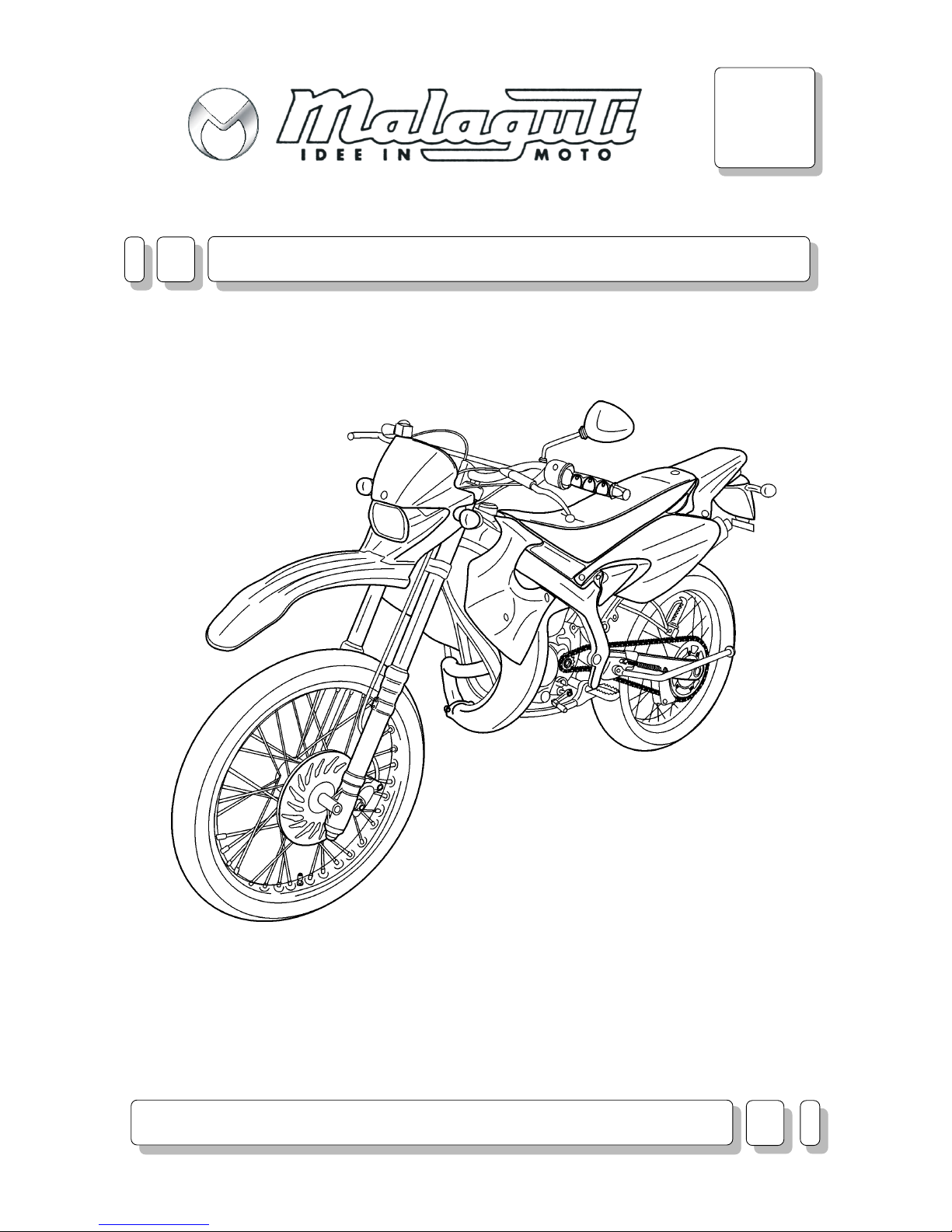
XTM - XSM
A
WORKSHOP MANUALS
CHASSIS
Page 2

Page 3
A
02.04 3
Introduction
CHAPTER
PAGEISSUE
CHASSIS
ENGLISH
SECTION 1
A - CHASSIS
SP
INTRODUCTION 1 4
Notes for easy consultation 1 5
Abbreviations 1 6
General work procedures 1 7
Editing symbols 1 9
GETTING TO KNOW YOUR MOTORBIKE 2 10
Specifications 2 10
Unpacking 2 12
Appearance check 2 12
Registration data 2 12
Anti-tampering label 2 12
Main components 2 13
Controls 2 14
Start switch/keys 2 14
Side stand 2 15
Display 2 15
Tires 2 16
Fuel tank 2 16
Coolant 2 17
Engine oil 2 17
Transmission oil 2 18
Brake fluid 2 18
Adjustment of engine idling speed 2 19
Shock absorber adjustment 2 19
Adjusting transmission chain tightness 2 19
DISASSEMBLY 3 20
Seat 3 20
Rear side casings 3 20
Tail section 3 20
Conveyor 3 21
Silencer 3 22
Muffler 3 22
Battery 3 23
Rear indicators 3 23
Tail light 3 24
Rear wing 3 24
Filter cartridge 3 25
Regulator 3 25
Flashlight 3 25
Rear chassis 3 26
Air filter suction box 3 26
SP
DISASSEMBLY 3 20
Shock absorber 3 27
Shift lever 3 27
Control unit 3 27
Oil tank 3 28
Oil level probe 3 28
Oil pipe fitting with filter 3 28
Fuel tank 3 29
Fuel cock 3 29
Throttle cable 3 30
Carburettor 3 30
Engine 3 31
Radiator 3 31
Side stand 3 32
Front indicators 3 32
Guard/front wing 3 32
Headlight 3 33
Display 3 33
Throttle control 3 33
Front brake pump 3 33
Clutch control 3 34
Handlebar 3 34
Front brake caliper 3 34
Removing the front brake calipers 3 35
Removing the front brake calipers 3 35
Speedometer sensor 3 35
Front wheel 3 36
Front brake disc 3 36
Fork head 3 37
Fork 3 37
Foot rests (lh/rh) 3 37
Rear brake lever 3 38
Rear brake pump 3 38
Rear wheel 3 38
Rear brake calipers 3 39
Removing the rear brake calipers 3 39
Rear disc brake 3 39
Chain crankcase 3 40
Fork 3 40
ASSEMBLY 4 41
Chassis torque wrench settings 4 41
TABLE OF CONTENTS
Page 4
A
4 05.03
Introduction
CHAPTER
PAGE ISSUE
CHASSIS
ENGLISH
SECTION 1
A - CHASSIS
INTRODUCTION
• This Workshop Manual describes the main electrical/mechanical checks, the essential checks, and the assembly of components supplied disassembled, in order to deliver a brand new motorcycle (the sequence of
operations is not binding).
• It is essential to follow the instructions with great care. Work carried out carelessly or, worse still, work that has
not been accomplished, can cause injuries and damage or, in the less serious cases, tiresome complaints.
“Schedules” (frequency of operations to accomplish during the guarantee period).
Note:
These manuals provide the necessary information and instructions for routine maintenance and servicing. This
information has been given to us by the engine manufacturers. We therefore decline all responsibility for any error,
omission or misrepresentation.
MALAGUTI reserves the right to make any changes and modifications hereto it deems necessary without prior
notice.
For further information and details, please contact the Malaguti S.p.A. Service Division.
MANUAL UPDATES
• Updated pages of this publication will be delivered by us (in a reasonable time) already punched and therefore
ready to be incorporated in the Manual. The superseded sheets should not be removed from the manual as they
remain applicable to the servicing of pre-modified engines.
• The table of contents will be duly updated in the event that new pages are inserted, which render the consulta-
tion of the manual difficult.
• IMPORTANT! The Workshop Manuals are to be considered as essential tools to be properly kept up-to-date so
as to maintain their “validity” over time.
Page 5
A
05.03 5
Introduction
CHAPTER
PAGEISSUE
CHASSIS
ENGLISH
SECTION 1
A - CHASSIS
X
W
Z
Y
NOTES FOR EASY CONSULTATION
MODIFIED PAGES
• Modified pages shall bear the same number as those in the previous edition /pre-modified ones,
followed by the letter M, with the date of issue appearing in the appropriate box.
• Modified pages may contain new illustrations; in this case, the added illustration (or illustrations) will bear the
number of the illustration on the former page, followed by a letter.
ADDITIONAL PAGES
• Any additional pages shall bear the last number of the section to which they belong, followed by the letter A and
the date of issue.
EDITING SYMBOLS
• Symbols have been provided for quick and easy reference (see page 9), identifying situations requiring utmost
attention or providing practical suggestions or simple information.
• These symbols may appear next to a text (in which case they refer solely to the text itself), next to a figure
(in which case they refer to the topic illustrated in the figure and to the relative text), or at the top of the page
(in which case they refer to all the topics dealt with in the page).
Note:
The meaning of the symbols should be duly memorised as their scope is to avoid having to repeat basic technical
concepts or safety recommendations. They are therefore to be considered as veritable “memory tags”. In case
of any doubt as to their meaning, consult the page in which they are fully described.
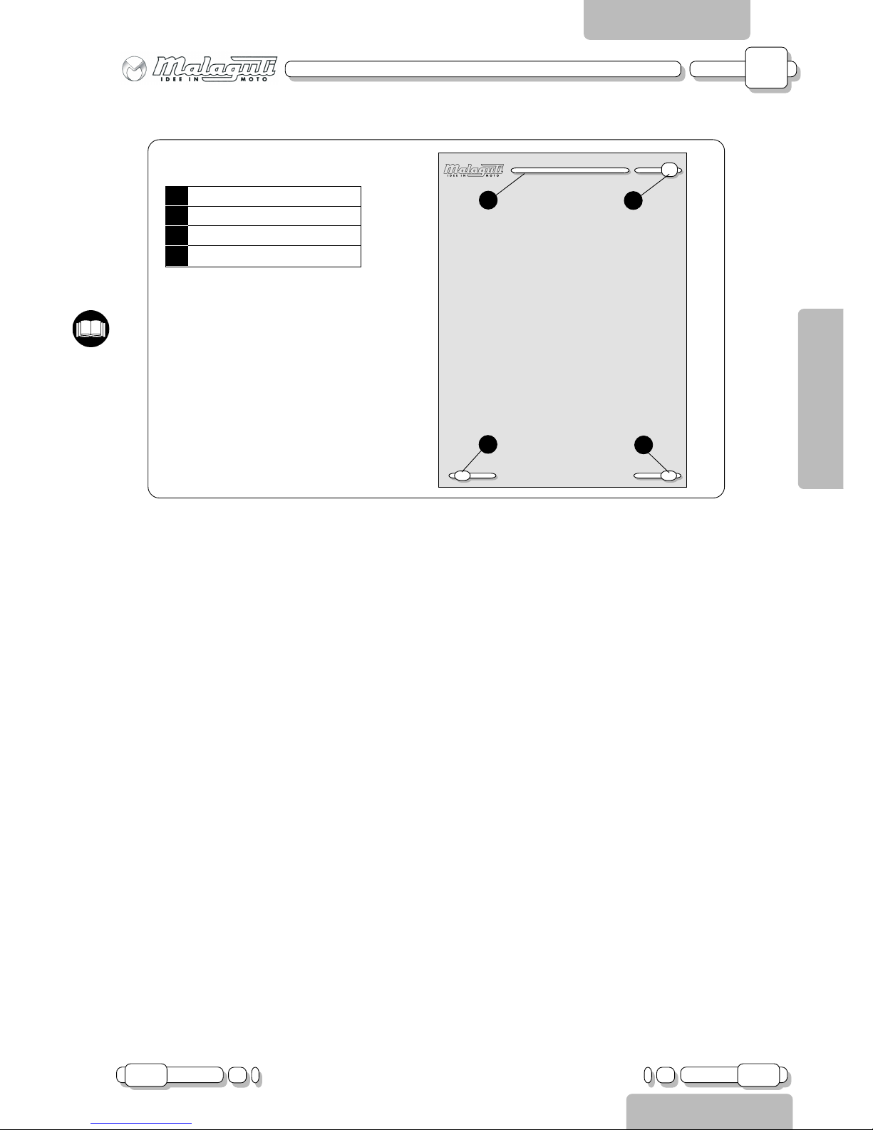
Y Chapter
X Section title
W Page n°
Z Date of issue
(RIGHT HAND PAGE)
PAGE LAYOUT
Page 6
A
6 05.03
Introduction
CHAPTER
PAGE ISSUE
CHASSIS
ENGLISH
SECTION 1
A - CHASSIS
ABBREVIATIONS
Note:
the letter V in the illustrations refers to retaining or adjusting screws. The number following this letter refers to the
number of the same type of screw in the unit or component described and illustrated. Letters not followed by a
number indicate a single screw. In case of different screws being referred to in the illustration, the letter V is
followed by a number and a small letter, for instance: (V4a).
Unless otherwise specified, units and components are reassembled by proceeding in the reverse order of removal.
F Figure
Cs Tightening torque
P Page
Pr Paragraph
S Section
Sc Diagram
T Table
V Screw
Page 7
A
05.03 7
Introduction
CHAPTER
PAGEISSUE
CHASSIS
ENGLISH
SECTION 1
A - CHASSIS
F. 1
F. 3
F. 2
GENERAL WORK PROCEDURES
• The advice, recommendations and warnings given hereafter are aimed at ensuring maximum work safety as
well as at considerably reducing the risk of accidents, personal injury, equipment damage and idle times. They
should therefore be strictly adhered to.
ADVICE:
• Only use quality tools and equipment.
• Only use equipment conforming to EU Directives for lifting the vehicle.
• During operations, always keep tools and equipment at hand, possibly laying them out according to the sequence in which
they are to be used. Absolutely avoid putting them on the vehicle itself, out-of-sight or in poorly accessible places.
• Always keep the work area clean and tidy.
• When tightening screws or nuts, start with the larger diameter or inner fasteners, and tighten them in progressive “pulls”
in accordance to a “criss-cross” pattern.
• Preferably use open-end box wrenches by “pulling” and not “pushing”.
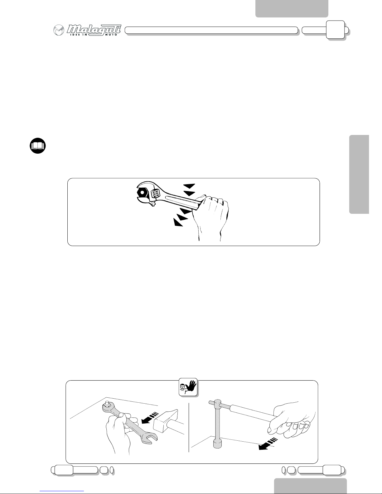
• Adjustable wrenches (F. 1) should only be used in case of emergency, i.e. when a properly sized wrench is not available.
they should preferably not be used as the movable jaw tends to open thus risking damaging or not properly tightening the
bolt to the correct torque.In any case, when using an adjustable wrench, take care to proceed as shown in Figure 1.
• Except for occasional customers, always make out and deliver to the customer a work sheet specifying the operations
performed, with notes as to any future checks eventually required.
RECOMMENDATIONS:
• Before carrying out any operation on the vehicle, wait for all parts to cool down.
• For operations requiring two mechanics, make sure that the various steps to be performed by each of them are
clearly defined and coordinated beforehand.
• Make sure that each component has been properly fitted before proceeding with the next one.
• Lubricate all parts (where applicable) before reinstalling them.
• Gaskets, O-rings, circlips and split pins must be replaced at every refitting.
• The torque settings specified in the manuals refer to the “final torque”, which must be attained progressively by
steps.
• Loosen and tighten aluminium alloy parts (covers) only after the engine has fully cooled down.
• Only use screwdrivers with sizes suitable to the screws to be loosened or tightened.
• Work in a comfortable position and ensure that the vehicle is stable.
• Never use a screwdriver as a lever or chisel.
• Never use pincers to loosen or tighten screws or nuts because, in addition to not providing a sufficient clamping
force, they may also damage the screw head or nut hexagon.
• Never tap the wrench with a hammer or other similar tools to loosen or tighten screws and nuts (F. 2).
• Never attempt to increase the lever arm by fitting a tube into the wrench (F. 3).
Page 8
A
8 05.03
Introduction
CHAPTER
PAGE ISSUE
CHASSIS
ENGLISH
SECTION 1
A - CHASSIS
F. 4
A
Never use open flames for any reason.
Never leave open containers or containers not suitable for holding fuel in passageways, close to heat
sources, etc
Never use petrol to clean the vehicle or the floor of the workshop. Always use low flash point solvents to
clean the vehicle components.
Never suck from or blow into the fuel pipe.
When welding, make sure that there are no flammable liquids in the vicinity. Always remove the tank, even
if completely empty, and disconnect the negative cable (-) from the battery.
Never leave the engine running in closed or poorly ventilated areas.
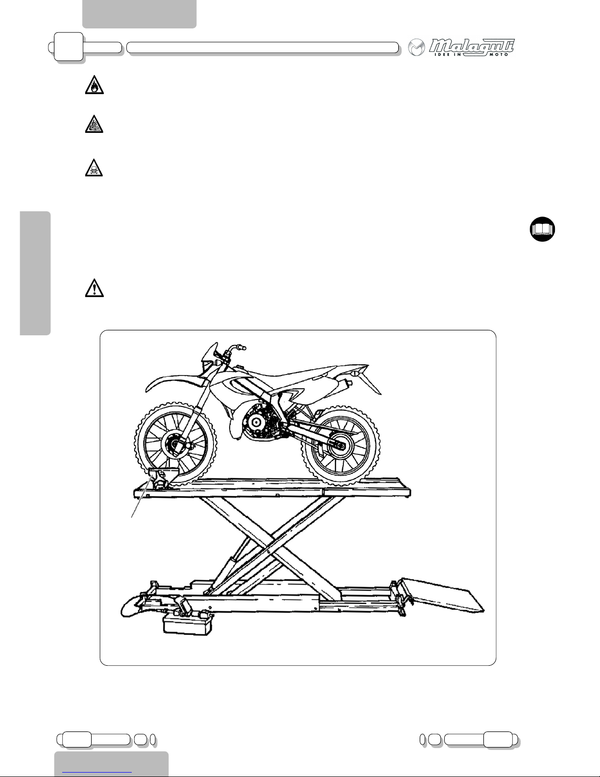
Before any servicing, make sure that the motorbike is perfectly stable.
The front wheel should preferably be anchored to the equipment (A - F.4) integral with the lifting board.
Page 9
A
05.03 9
Introduction
CHAPTER
PAGEISSUE
CHASSIS
ENGLISH
SECTION 1
A - CHASSIS
R
M
L
H
F
A
B
D
C
I
G
E
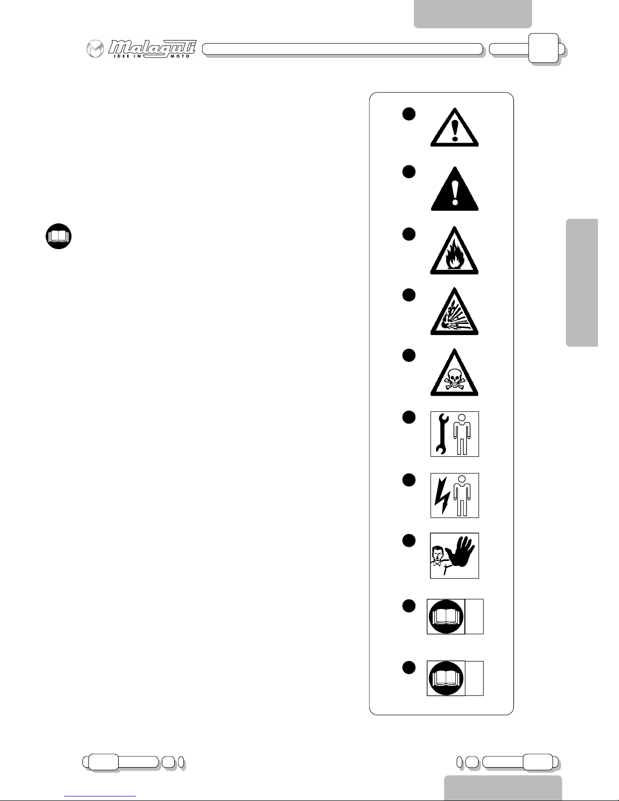
EDITING SYMBOLS
A) CAUTION!
Recommendations and precautions regarding rider safety and
motor vehicle integrity.
B) WARNING!
Situations entailing the risk of personal injury to maintenance
or repair mechanics, other workshop personnel or third parties, or damage to environment, vehicle or equipment.
C) FIRE HAZARD
Indicates operations which may constitute a fire hazard.
D) RISK OF EXPLOSION
Indicates operations which may constitute a risk of explosion.
E) TOXIC FUMES
Indicates a possibility of intoxication, inflammation or corrosion.
F) MECHANICAL MAINTENANCE
Operations to be performed only by an expert mechanic.
G) ELECTRICAL MAINTENANCE
Operations be performed only by an expert electrical/electronic technician.
H) NO!
Operations to be absolutely avoided.
I) ENGINE SERVICE MANUAL
Indicates information which may be obtained by referring to
said manual.
L) SPARE PARTS CATALOGUE
Indicates information which may be obtained by referring to
said catalogue.
Page 10
A
10 02.04
CHAPTER
PAGE ISSUE
CHASSIS
ENGLISH
SECTION 2
Getting to know your motorbike
SECTION 2
A - CHASSIS
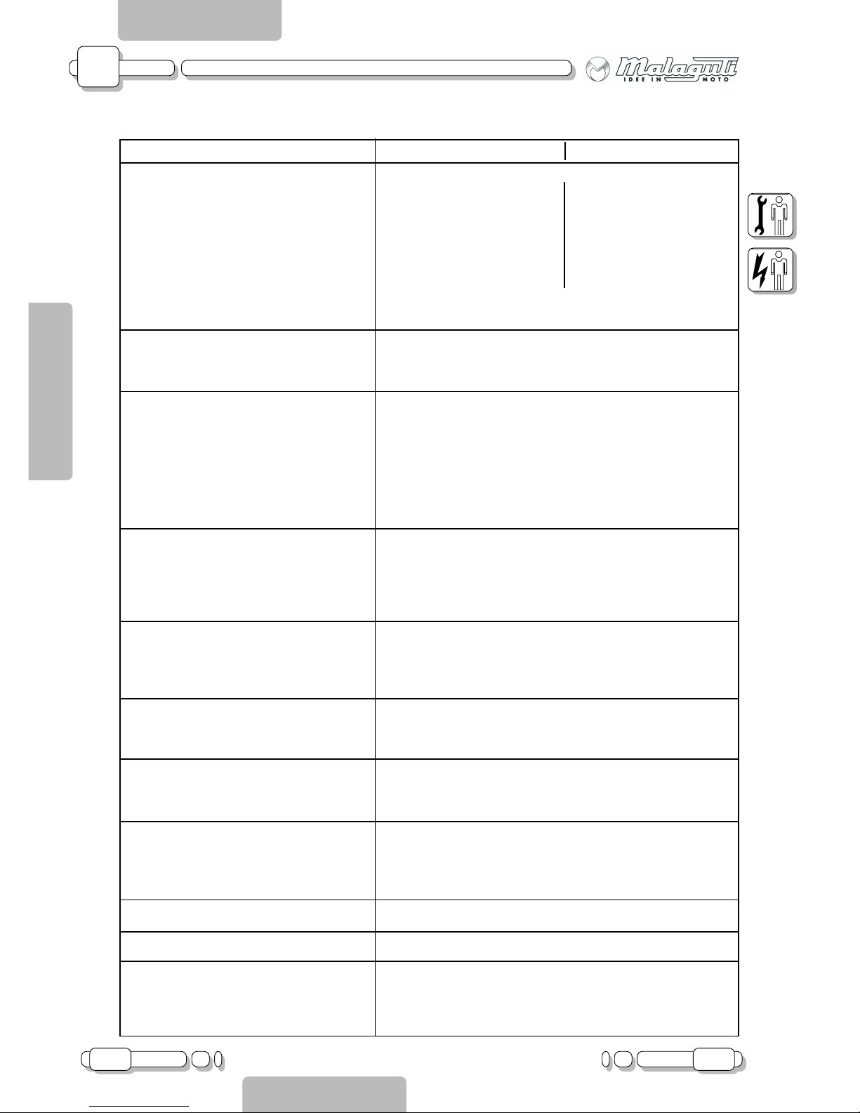
SPECIFICATIONS
ENDURO SUPERMOTARD
Dimensions:
Length 2050 mm 2000 mm
Width 850 mm
Height 1160 mm 1115 mm
Wheel base 1350 mm ± 20
Seat height 910 mm 880 mm
Minimum ground clearance 345 mm 315 mm
Minimum turning radius 2320 mm 2240 mm
Front wheel stroke 190 mm
Rear wheel stroke 220 mm
Weight:
Kerb weight 104 kg
Maximum load 160 kg
Engine:
Type 2-stroke, liquid-cooled
Cylinder arrangement single-cylinder, vertical
Displacement 49 cm
3
Bore x stroke 40.3 x 39 mm
Compression ratio 12:1 ± 0.5
Starting system Kickstarter
Lubricating system separate lubrication
Type of oil:
Engine oil semi-synthetic oil, according to API TC TS C3 standards
Total amount 1.1 L
Transmission oil SAE 10W30 type SE
Total amount 0.82 L
Fuel:
Type RON 91 premium grade unleaded petrol
Fuel tank capacity 6.5 L
Reserve amount 1.8 L
Carburettor:
Type PHBN 16
Manufacturer DELL’ORTO
Chassis:
Chassis welded steel tubular bar.
Caster angle 28°
Spark plug:
Type BR9ES
Manufacturer NGK
Electrode gap 0.6 ~ 0.7 mm
Clutch mechanical, multiple disc, oil-bath type
Air filter sponge, 45ppi
Cooling system
Type water-cooled
Antifreeze-water mixture ratio 1:1
Total amount 0.55 L
Model:
Page 11
A
02.04 11
CHAPTER
PAGEISSUE
CHASSIS
ENGLISH
SECTION 2
Getting to know your motorbike
SECTION 2
A - CHASSIS
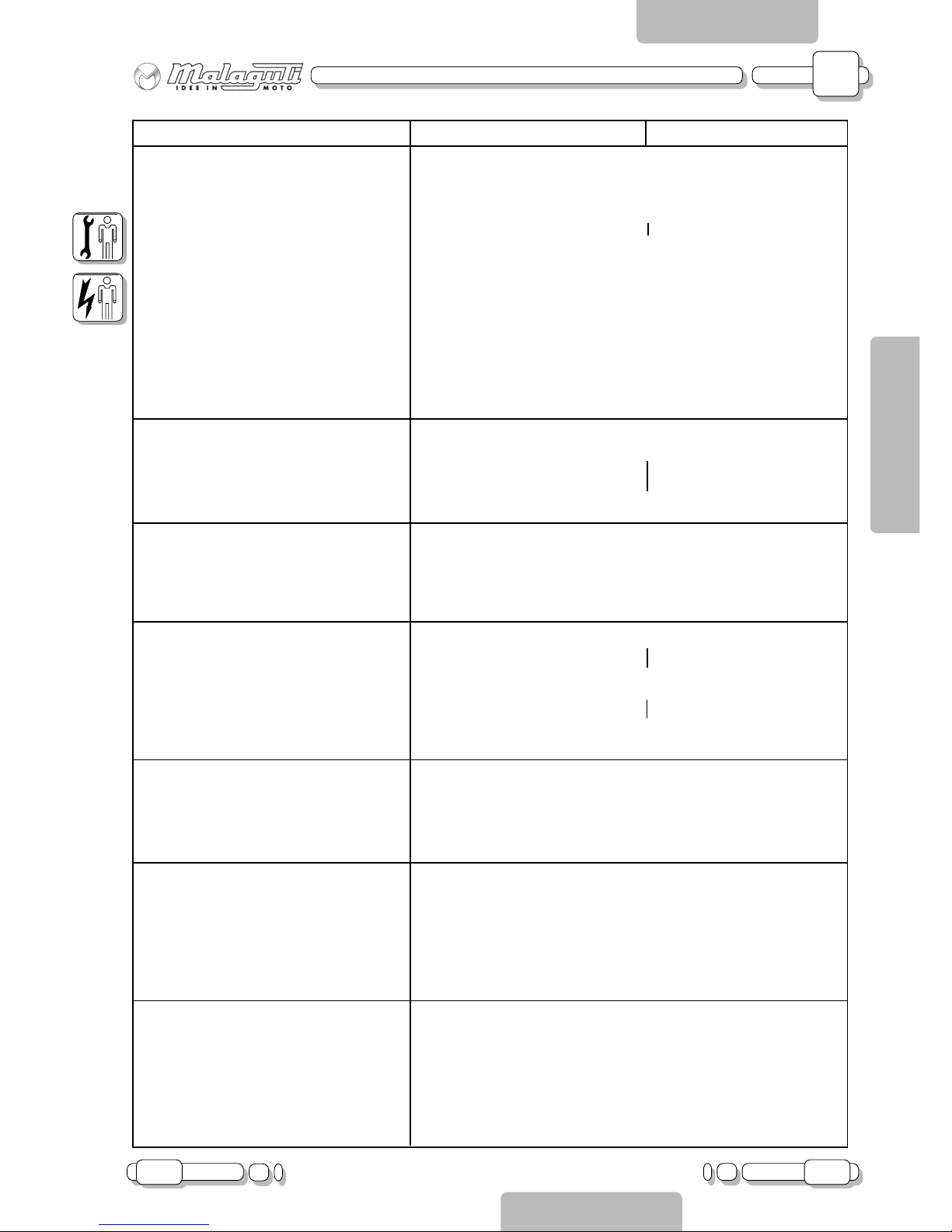
ENDURO SUPERMOTARD
Transmission:
Primary reduction system helical gears
Primary reduction ratio z71 / z20 (3,55)
Secondary reduction system chain drive
Secondary reduction ratio z50 / z11 (4,54) z48 / z11 (4,36)
Transmission type mechanical, 6-speed
Type left foot
Gear ratio:
1st speed z12 / z36 1:3
2
nd
speed z16 / z33 1:2.06
3
rd
speed z19 / z29 1:1.52
4
th
speed z22 / z27 1:1.23
5
th
speed z24 / z25 1:1.04
6
th
speed z25 / z24 1:0.96
Tires:
Type with tube
Front 80/90-21 48P 100/80-17 52S
Rear 110/80-18 58P 130/70-17 62S
Manufacturer PIRELLI
Tire pressure (ambient temperature):
Front 0 ~ 90 kg 2.0 bar
Rear 0 ~ 90 kg 2.2 bar
Front 90 kg ~ max. load 2.0 bar
Rear 90 kg ~ max. load 2.2 bar
Brakes:
Front hydraulic disk type Ø240 mm hydraulic disk type Ø259 mm
Calipers with two pistons
Operation right hand operation
Rear hydraulic disk type Ø218 mm hydraulic disk type Ø218 mm
Calipers with two pistons
Operation right foot operation
Suspensions:
Front telescopic fork
Max. stroke 190 ± 2 mm
Rear swingarm
Max. stroke 44 ± 2
Electrical equipment:
Ignition system C.D.I. control unit.
Generator, rated power FLYWHEEL MAGNETO, 95W
Type of battery calling for maintenance
Battery capacity 12 4 Ah
Fuel sensor electrical floating probe
Horn 12 V DC
Lights
Headlight 12V 35/35 W
Tail-light 12V P21/5 W
Indicators front/rear 12V 10W x 4
Indicator lights LED
Parking light 12V 4W (Switzerland version only)
Low beam indicator light 12V 1,2W (Switzerland version only)
Number plate light 12V 5W (Switzerland version only)
Model:
Page 12
A
12 05.03
CHAPTER
PAGE ISSUE
CHASSIS
ENGLISH
SECTION 2
Getting to know your motorbike
SECTION 2
A - CHASSIS
P
MARCHIO DI FABBRICA: MALAGUTI
S.P.A.
1 -
---------------------
2 -
---------------------
3 -
---------------------
4 -
----------------------
5 -
----------------------
6 -
-----------------------
7 -
-----------------------
8 -
-----------------------
9 -
------------------------
10 -
---------------------
A
V
F.1i F.2i
A
I
UNPACKING
• Unpack the motorcycle following the instructions printed on the pack, which must be disposed of in accordance
to the laws in force.
APPEARANCE CHECK
• Make sure all plastic components have been correctly fitted. In particular check the vehicle for scratches, marks,
etc.
REGISTRATION DATA
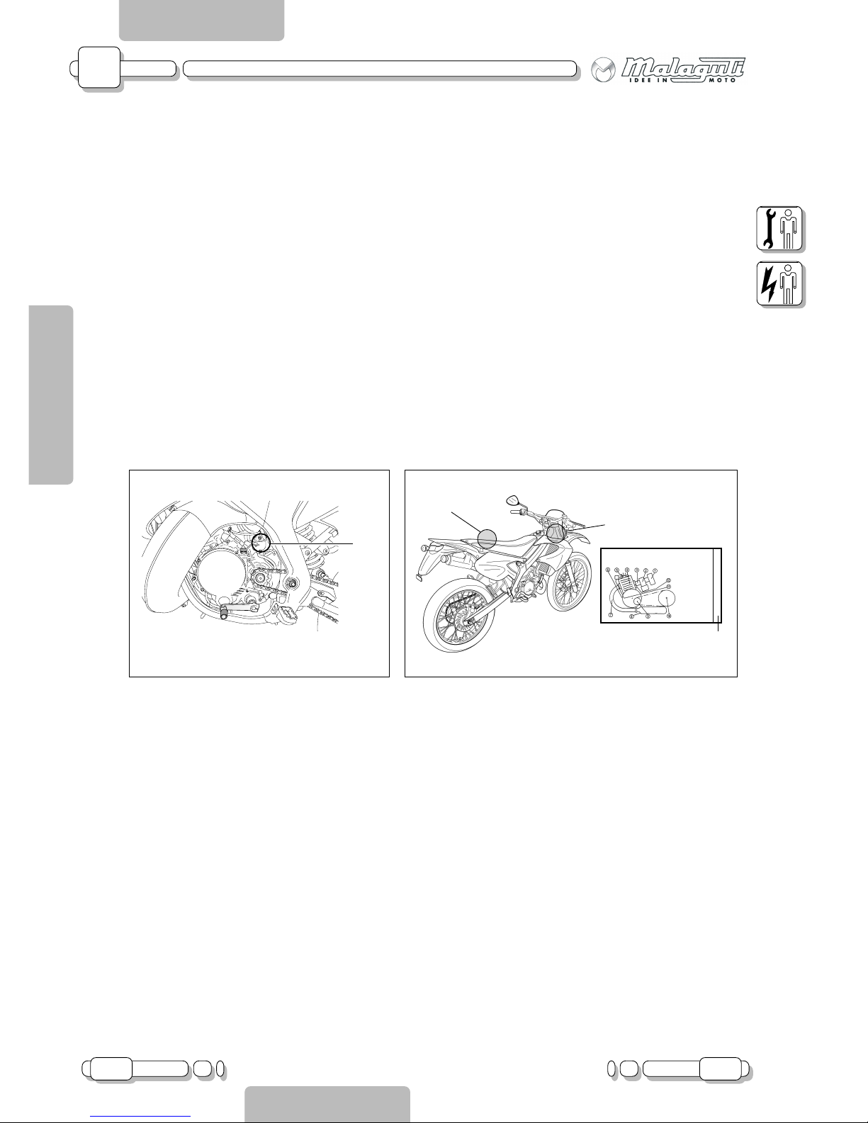
ENGINE REGISTRATION NUMBER
Engine registration data (P - F.1i) is on the left crankcase.
VEHICLE REGISTRATION NUMBER
The vehicle’s registration number (I - F2i) is stamped on the steering rod. The vehicle registration number is
used to identify the motorcycle.
ANTI-TAMPERING LABEL
The anti-tampering label (A - F.2i) is located under the seat. It bears all the vehicle registration data envisaged by the 97/24/CE Directive.
If you intend to replace the compartment under the seat, make sure it is provided with the anti-tampering
label.
When ordering spare parts, also quote the vehicle registration data.
This label identifies the type of flywheel installed on the engine (V - F.2i); this piece of information will be
needed to correctly set the functions of the digital instrument board, should this be necessary.
This label must be neither removed nor changed.
Page 13
A
02.04 13
CHAPTER
PAGEISSUE
CHASSIS
ENGLISH
SECTION 2
Getting to know your motorbike
SECTION 2
A - CHASSIS
11
6
12
10
7
8
9
1
2
3
5
4
12
F.3i
F.4i
13
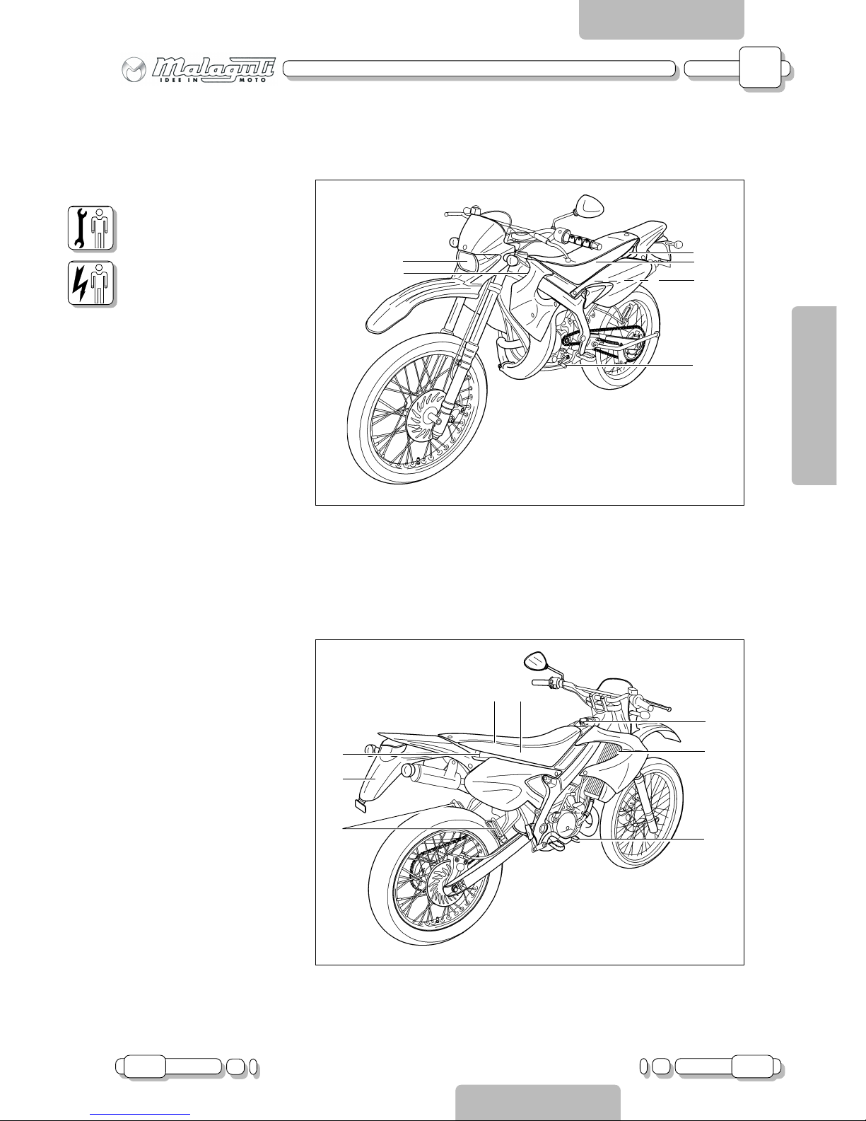
MAIN COMPONENTS
(Left hand side)
1. Headlight
2. Oil tank
3. Battery
4. Air filter
5. Shift pedal
MAIN COMPONENTS
(Right hand side)
6. Radiator
7. Owner’s tool bag
8. Fuse
9. Fuel tank cap
10. Rear brake pedal
11. Passenger foot rests
12. Passenger holder
13. Number plate light +
number plate holder
(SWITZERLAND only)
Page 14
A
14 02.04
CHAPTER
PAGE ISSUE
CHASSIS
ENGLISH
SECTION 2
Getting to know your motorbike
SECTION 2
A - CHASSIS
141517
20
21
22
19
F.5i
F.6i
23
1816
24
25
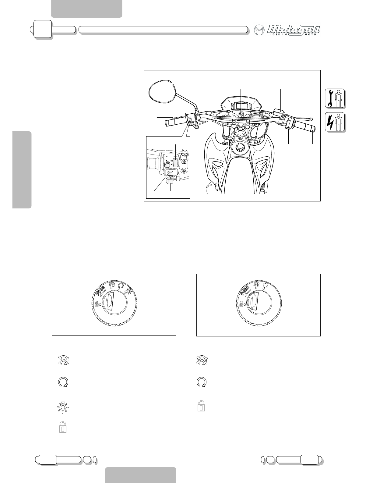
CONTROLS
Controls/Instruments
14. Main switch
15. Clutch lever
16. Turn signal switch
17. Digital, multifunction instrument
board
18. Manual starter lever
19. Front brake pump
20. Mode switch
21. Front brake lever
22. Throttle grip
23. Rear-view mirror (*)
24. Horn switch
25. Low beam/high beam light
switch (**)
(*) GREAT BRITAIN version: the rear view mirror is on the right hand side of the handlebar.
SWITZERLAND version: there are two rear view mirrors, one on the right and one on the left hand side of the handlebar.
(**) SWITZERLAND version only.
START SWITCH/KEYS
• The main switch controls the ignition circuit and steering lock.
Up to chassis n° 7086713:
: all electrical contacts are disconnected.
: the contacts are activated; the engine can
start.
: lights are on
: the steering lock is on.
From chassis n° 7086714:
: all electrical contacts are disconnected.
: the contacts are activated; the engine can
start and the lights come on.
: the steering lock is on.
Page 15
A
02.04 15
CHAPTER
PAGEISSUE
CHASSIS
ENGLISH
SECTION 2
Getting to know your motorbike
SECTION 2
A - CHASSIS
1
2
3
5
6
4
F.7i
F.8i
7
(*)
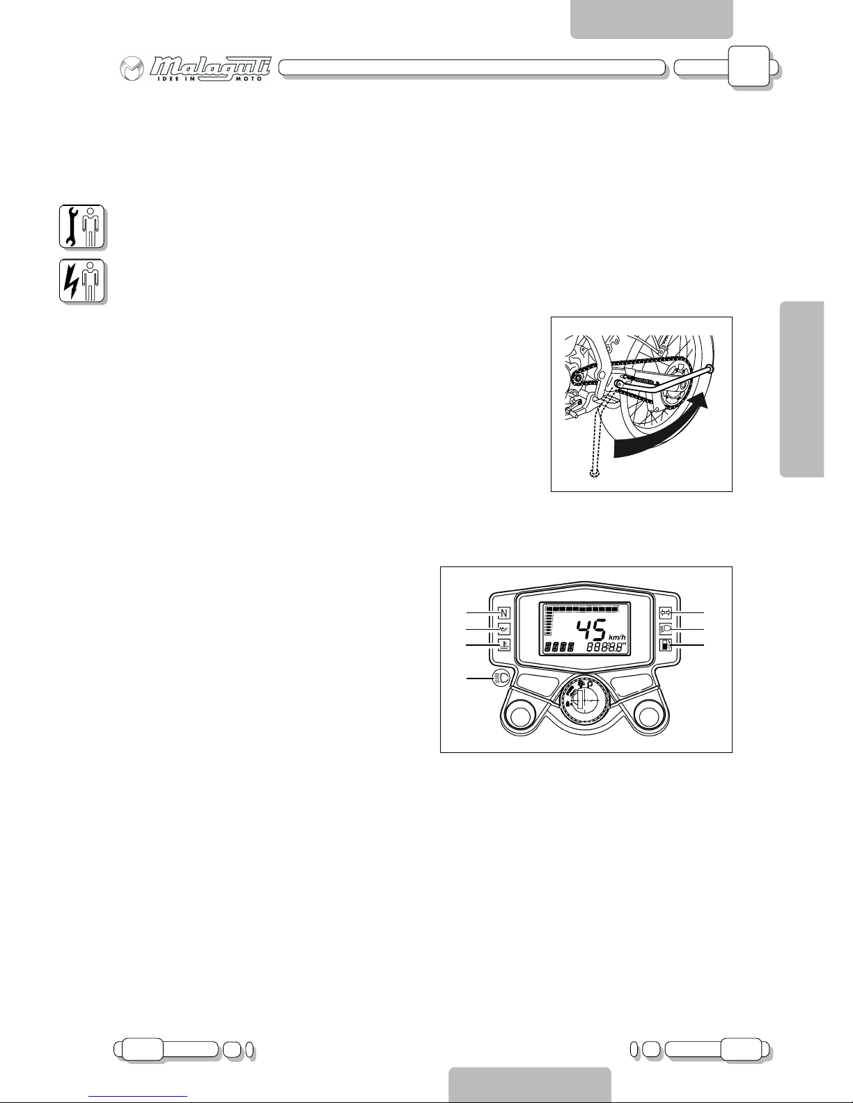
SIDE STAND
Make sure the sidestand is correctly fitted and that it moves correctly; check
the spring holding the sidestand in place on a regular basis.
DISPLAY
1- Turn indicator light
This light blinks when the turn indicator is pushed
towards left or towards right.
2- Low beam indicator light
This light comes on when the low beam of the headlight is switched on.
3- Fuel level warning light
This light comes on when the fuel level is low (reserve).
Fill the fuel tank.
4- Coolant temperature warning light
This light comes on when the temperature of the coolant is too high.
When this light comes on, stop the engine at once.
5- Neutral indicator light “N”
This light comes on when the transmission is in neutral position.
6- Oil level warning light
This warning light comes on when the oil level is low.
7 (*) - Low beam indicator light
SWITZERLAND version only.
This indicator comes on when the low beam headlight is operated.
KEYS
The vehicle is supplied with two keys featuring a code number, which have the following functions:
• Providing the ignition contact
• Turning the lights on
• Locking the steering system.
STEERING LOCK
Locking: turn the handlebar all the way to the right or left, push the key in and turn it counter-clockwise.
Disengaging: turn the key clockwise.
Page 16
A
16 05.03
CHAPTER
PAGE ISSUE
CHASSIS
ENGLISH
SECTION 2
Getting to know your motorbike
SECTION 2
A - CHASSIS
bar
(psi)
2.0 2,2
(29,0) (31.9)
2.0 2,2
(29,0) (31.9)
X
Y
bar
(psi)
2.0 2,2
(29,0) (31.9)
2.0 2,2
(29,0) (31.9)
X
Y
SUPERMOTARD:
ENDURO:
X
Y
T
F.9i
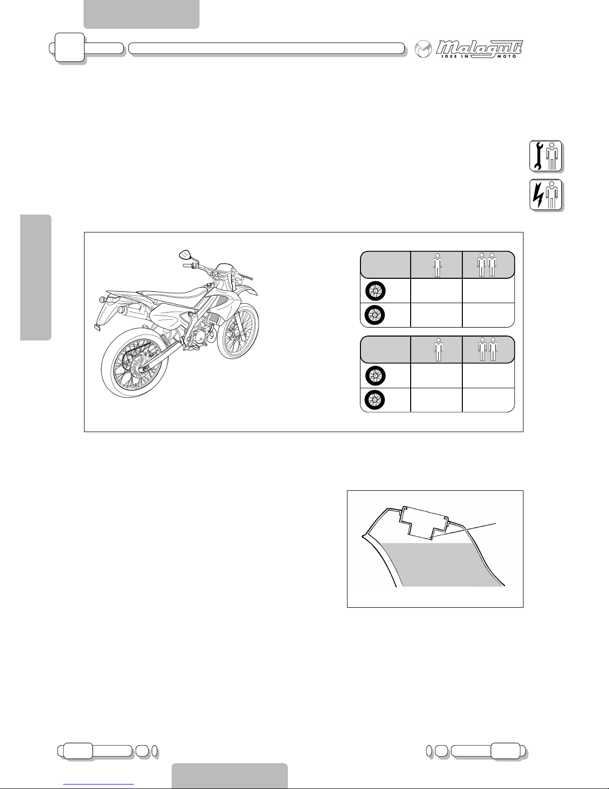
TIRES
Dimensions: 80/90 - 21 48P (enduro, front)
110/80 - 18 58P (enduro, rear)
100/80 - 17 52S (supermotard, front)
130/70 - 17 62S (supermotard, rear)
TIRE PRESSURE CHECK
Tire pressure must be checked when the tires are cold.
FUEL TANK
The tap of the fuel tank is of the pressure type; it therefore calls for
no manual intervention.
Unscrew the cap and fill the tank. Do not overfill the fuel tank (T F.9i); Immediately wipe off spilled fuel.
Use regular unleaded petrol with an octane of RESEARCH 95.
Fuel tank capacity:
Total: 6.5 L
Reserve amount: 1.8 L
Page 17
A
05.03 17
CHAPTER
PAGEISSUE
CHASSIS
ENGLISH
SECTION 2
Getting to know your motorbike
SECTION 2
A - CHASSIS
T
U
F
F.10i
F.11i
T
F.12i
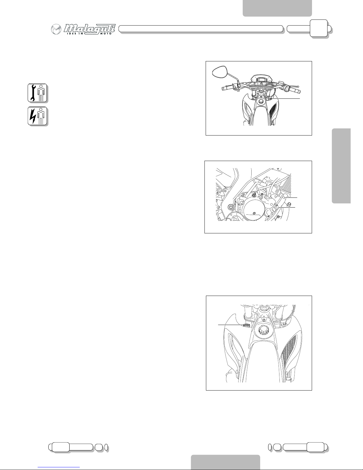
COOLANT
CHECK
1. Remove the cap (T - F.10i) when the engine is cold and exhaust
any residual pressure.
2. The coolant level must be checked on a cold engine since the
level varies with engine temperature. The coolant should be between the minimum and maximum level marks.
3. If the level is low, add coolant.
4. Refit the cap.
REPLACEMENT
Changing the coolant
1. Park the vehicle on a level surface and put a pan under the
radiator.
2. Remove the clamp (F - F.11i).
3. Detach the pipe (U - F.11i).
If you need too much coolant to reach the recommended level or
if you need to top up too frequently, check the entire cooling
system.
ENGINE OIL
There is an electrical contact inside the tank that turns the red
reserve light of the instrument board on when the tank is running
out of lubricant.
To add oil, remove the cap (T - F.12i) and carefully pour the oil
inside.
Recommended oil: SYNTHETIC 2-STROKE ENGINE OIL
JASO FC or ISO-LEGA
Page 18
A
18 05.03
CHAPTER
PAGE ISSUE
CHASSIS
ENGLISH
SECTION 2
Getting to know your motorbike
SECTION 2
A - CHASSIS
R
S
F
MIN
MAX
MIN
A
V2
F.13i
F.14i
F.15i
B
TRANSMISSION OIL
Replacement
Park the vehicle on flat ground.
2.Start the engine and warm it up for several minutes.
3.Stop the engine. Place an oil pan under the engine
and remove the filler cap (R - F.13i).
4.Remove the drain screw (S - F.13i) and the screw (F F.13i) to drain oil.
5.Reinstall the drain screw (S - F.13i) and tighten it.
6.Fill the engine with oil until this is dripping from the
level control hole (F - F.13i). Fit the screw back into the
hole (F - F.13i), install the oil filler cap (R - F.13i) and
tighten it.
The use of SAE 10W 30 oil is recommended.
Start the engine and let it warm up for a few minutes.
While it is warming up, check for oil leakage. If oil is
leaking, immediately turn off the engine and locate the
cause.
BRAKE FLUID
CHECK
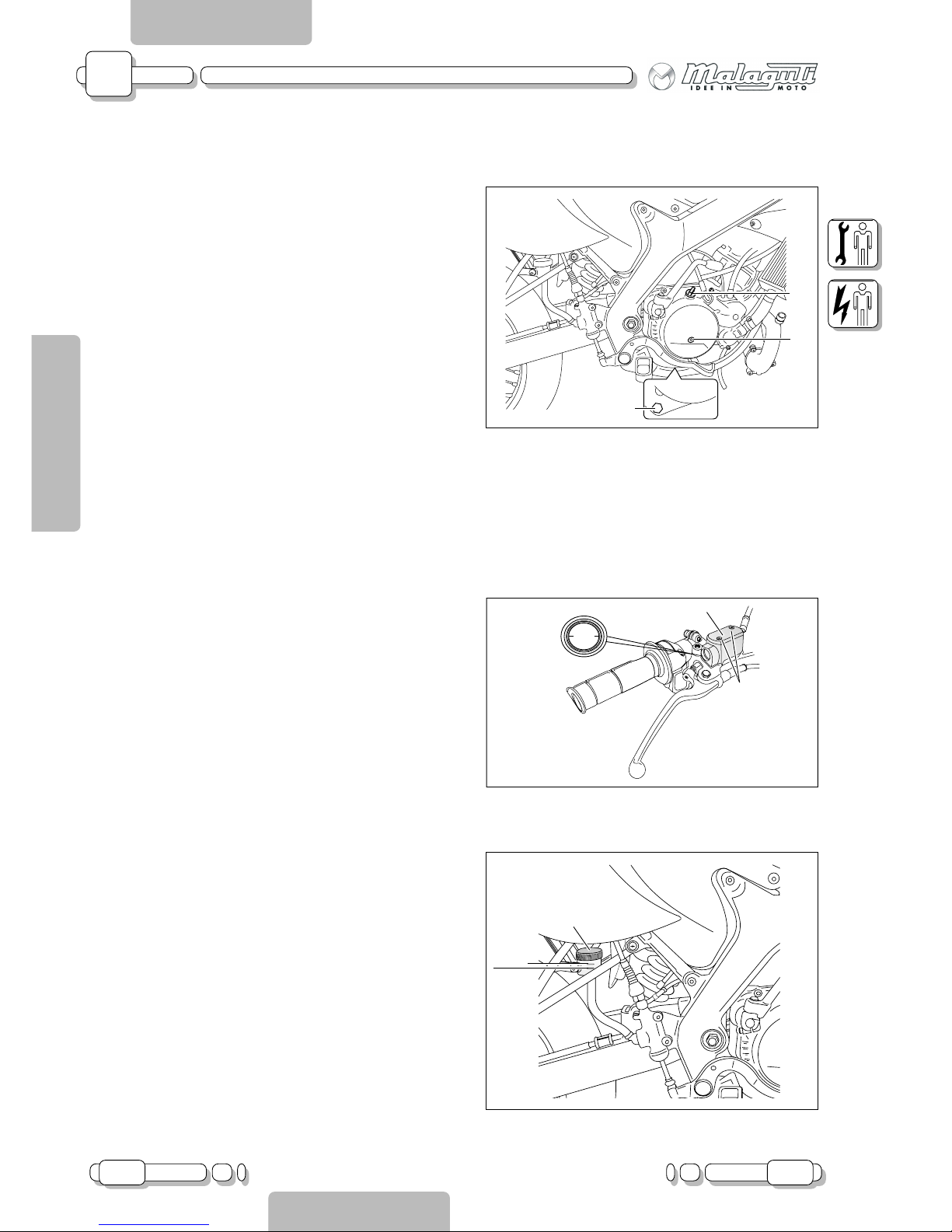
When checking the fluid level, make sure that the top
end of the main cylinder is horizontal when the handlebar is turned.
Make sure the brake fluid level of the rear brake reservoir is above the minimum level mark. As far as the front
brake is concerned, the level of fluid can be checked
through the sight glass on the pump.
REPLACEMENT
Front brake: remove the cap (A - F.14i) after loosening
the screws (V2 - F.14i).
Rear brake: remove the cap (B - F.15i).
Brake fluid quality must comply with the specified standards; brake fluid may deteriorate rubber gaskets, causing leaks and impairing brake operation.
Recommended brake fluid: DOT 4
Page 19
A
05.03 19
CHAPTER
PAGEISSUE
CHASSIS
ENGLISH
SECTION 2
Getting to know your motorbike
SECTION 2
A - CHASSIS
G
F.16i
M
F.17i
F.18i
B
V
C
G
25 ÷ 40 mm
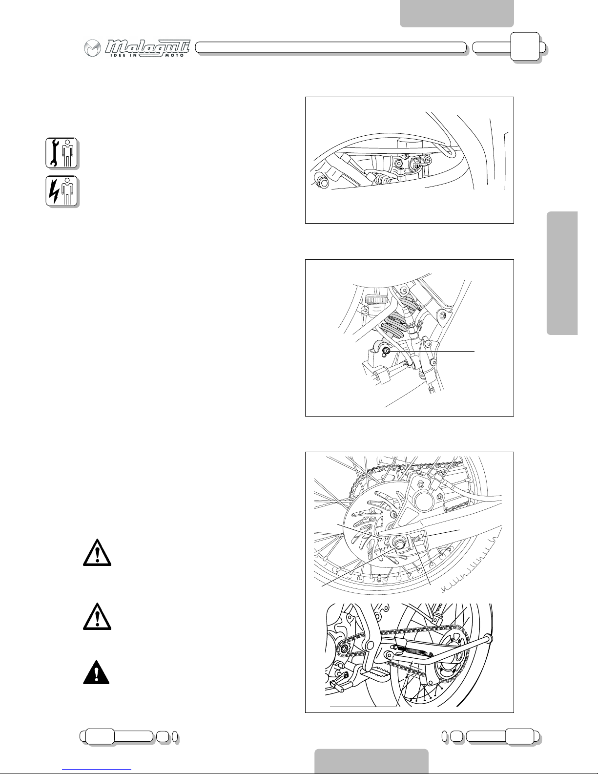
ADJUSTMENT OF ENGINE IDLING SPEED
Start the engine and warm it up for several minutes at
about 1000-2000 RPM, while occasionally revving it to
4000-5000 RPM. The engine is warm when it quickly
responds to the throttle.
To adjust engine idling speed, turn the throttle stop screw
(G - F.16i). Turn the screw clockwise to increase idling
speed or counter-clockwise to decrease it.
Check engine idling speed with an electronic revolution
counter connected to the spark plug cable.
SHOCK ABSORBER ADJUSTMENT
The vehicle’s seat can be lowered by moving the lower
fixing element (M - F.17i), double hole in the bottom
fixing bracket).
ADJUSTING TRANSMISSION CHAIN
TIGHTNESS
To adjust chain tightness, loosen the wheel fixing nut
(B - F.18i) and the lock nut (V - F.18i) and turn the
adjustment screw (C - F.18i). After adjusting, tighten
the lock nut (V - F.18i) and nut (B - F.18i).
This operation must be performed on both
sides of the rear fork; adjustment must be
identical on both sides; to obtain this condition, refer to the scale (G - F.18i) located
on the fork.
An excessively taut chain will put the engine and drive components under excessive strain; maintain chain tightness within the specified limits (F.18i).
Whilst carrying out these adjustments, hold
the vehicle firmly in place, otherwise it will
fall over.
Page 20
A
20 05.03
CHAPTER
PAGE ISSUE
CHASSIS
ENGLISH
SECTION 2
Disassembly XTM - XSM
SECTION 3
A - CHASSIS
F. 1
V
V4
F. 2
V2
F. 3
V4
F. 3b
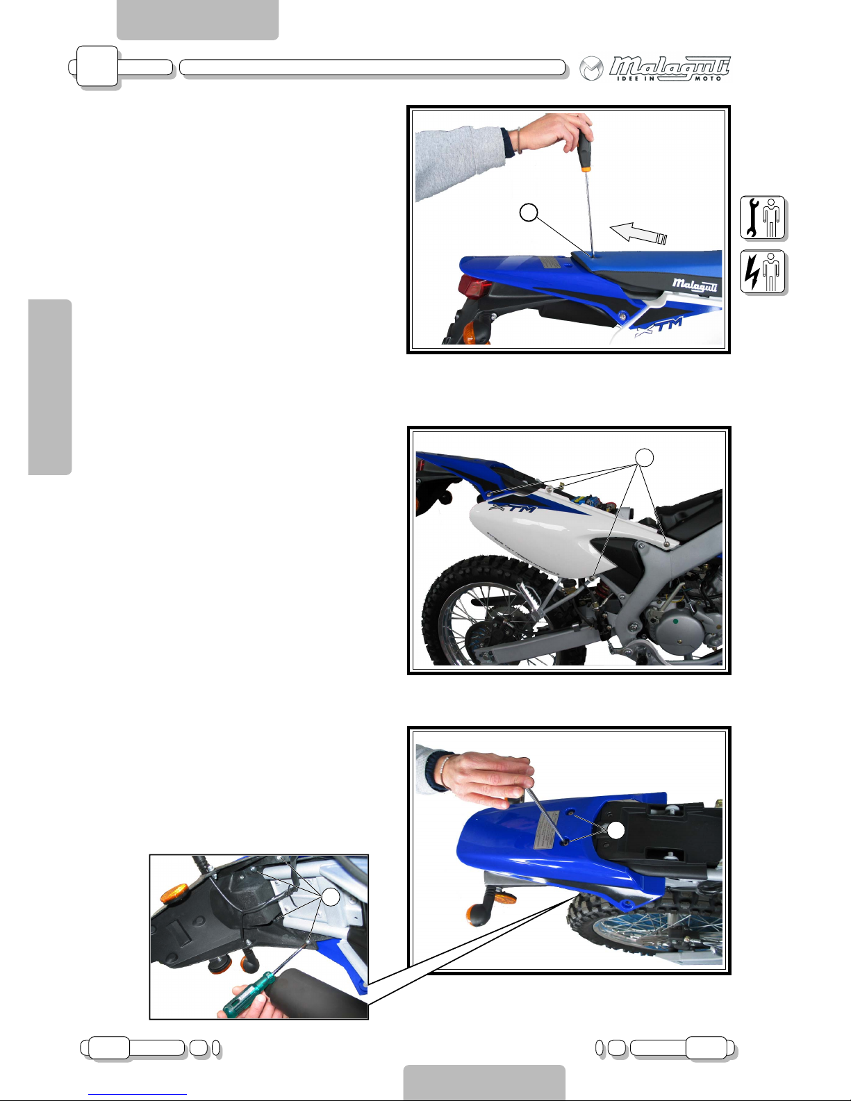
SEAT
Loosen the screw (V - F.1) and release the seat
from the chassis. Pull it out rearwards.
REAR SIDE CASINGS (rh / lh)
• (Remove seat)
Loosen the screws (V4 - F.2) and remove the rear
side casing (left or right).
TAIL SECTION
• (Remove seat and left/right rear side casing)
Undo fixing screws (V2 - F.3) and the screws (V4 F.3b).
Page 21
A
05.03 21
CHAPTER
PAGEISSUE
CHASSIS
ENGLISH
SECTION 2
Disassembly XTM - XSM
SECTION 3
A - CHASSIS
F. 4
F. 5
F. 6
V2
V
V2
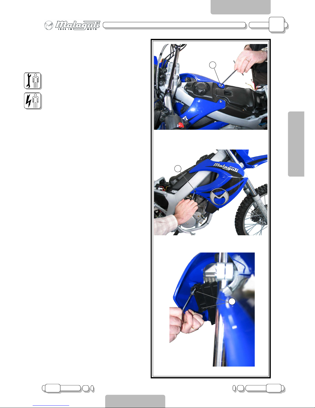
CONVEYOR (right and left)
• (Remove seat)
Undo the screws (V2 - F.4), the side screws (V F.5) and the front screws (V2 - F.6).
Page 22
A
22 05.03
CHAPTER
PAGE ISSUE
CHASSIS
ENGLISH
SECTION 2
Disassembly XTM - XSM
SECTION 3
A - CHASSIS
F. 8
V
B
A
F. 9
D
C
F. 7
V2
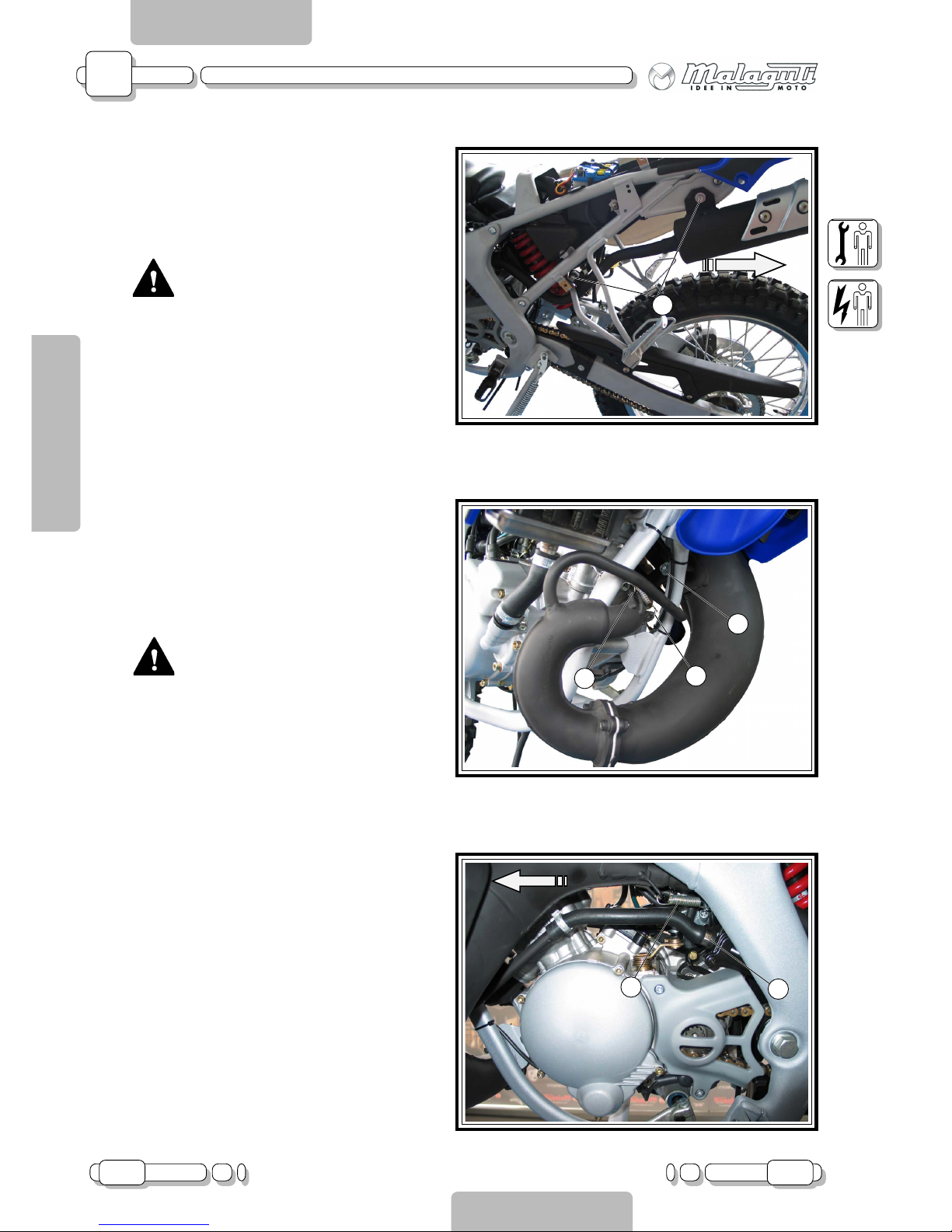
SILENCER
• (Remove seat and left hand side casing)
Remove the spring (D - F.9).
Undo the screws (V2 - F.7) and remove the silencer by pulling it rearwards.
CAUTION!!!
Before removing, make sure the silencer has cooled down.
MUFFLER
• (Remove seat and left hand side casing)
Remove the springs (A and B - F.8), fastened to
the cylinder.
Undo the screw (V - F.8).
CAUTION!!!
Before removing, make sure the muffler has cooled down.
Remove the clamp (C - F.9) from the tube of the
secondary air valve and detach the tube from its
fitting.
Remove the spring (D - F.9) and remove the muffler
by pulling it frontwards.
Page 23
A
05.03 23
CHAPTER
PAGEISSUE
CHASSIS
ENGLISH
SECTION 2
Disassembly XTM - XSM
SECTION 3
A - CHASSIS
F.10
A
F.10b
C
B
D
F. 11
F.12
V
V1
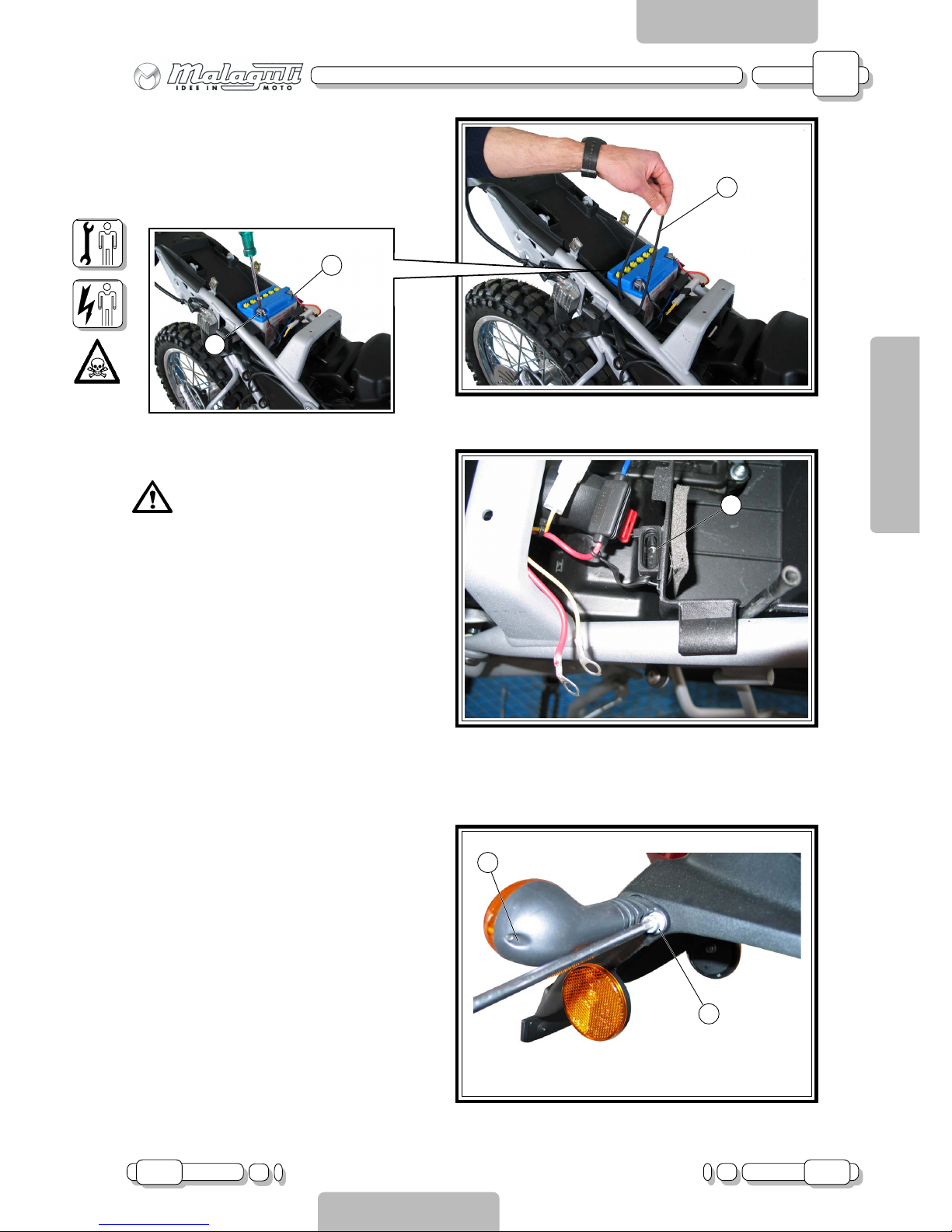
BATTERY
• (Remove seat)
Remove the elastic band (A - F.10) and detach the
battery cables (B and C - F.10b).
Release the fuse carrier (D - F.11) from the clamp.
Caution!!! When refitting the battery,
pay attention to the exhaust pipe.
REAR INDICATORS
Undo the screw (V - F.1).
Remove the glass cover and detach the lamp socket cables.
Undo the fixing screw (V - F. 12).
Page 24
A
24 05.03
CHAPTER
PAGE ISSUE
CHASSIS
ENGLISH
SECTION 2
Disassembly XTM - XSM
SECTION 3
A - CHASSIS
F.13
A
F.13b
V2
F.15
F.14
V4
V2
F
V3
F.14b
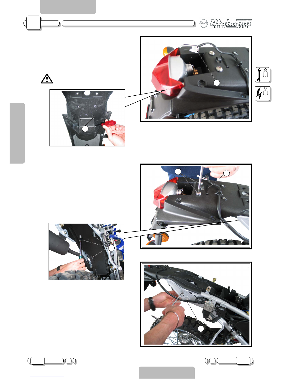
TAIL LIGHT
• (Remove seat and tail section)
Disconnect the cables (A - F.13) and undo the
screws (V2 - F.13b).
Caution!!! When refitting, pay attention
to the Fast-on sequence; (see wiring
diagram).
REAR WING
• (Remove seat, side casings and tail section)
Cut the cable clamp (F - F.14).
Undo the screws (V2 - F.14) and the screws (V4 F.15), on both sides.
Undo the screws (V3 - F.14b).
Page 25
A
05.03 25
CHAPTER
PAGEISSUE
CHASSIS
ENGLISH
SECTION 2
Disassembly XTM - XSM
SECTION 3
A - CHASSIS
F.16
F.17
F.18
I
V
C
V2
M
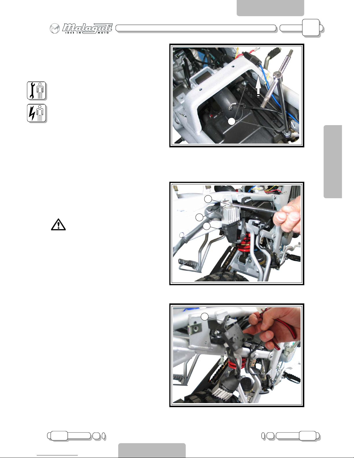
FILTER CARTRIDGE
• (Remove seat and battery)
Undo the screws (V2 - F.16) and remove the filter
cartridge.
REGULATOR
• (Remove seat and rear right hand casing)
Detach the connector (C - F.17) and undo the screw
(V - F.17).
Caution!!! When refitting, remember
to reconnect the earth cables (M F.17).
FLASHLIGHT
• (Remove seat and rear right hand casing)
Detach the connector and open the snap lock (I F.18).
Page 26
A
26 05.03
CHAPTER
PAGE ISSUE
CHASSIS
ENGLISH
SECTION 2
Disassembly XTM - XSM
SECTION 3
A - CHASSIS
F.19
V4
F.20
F.21
F.21b
V3
V3
F
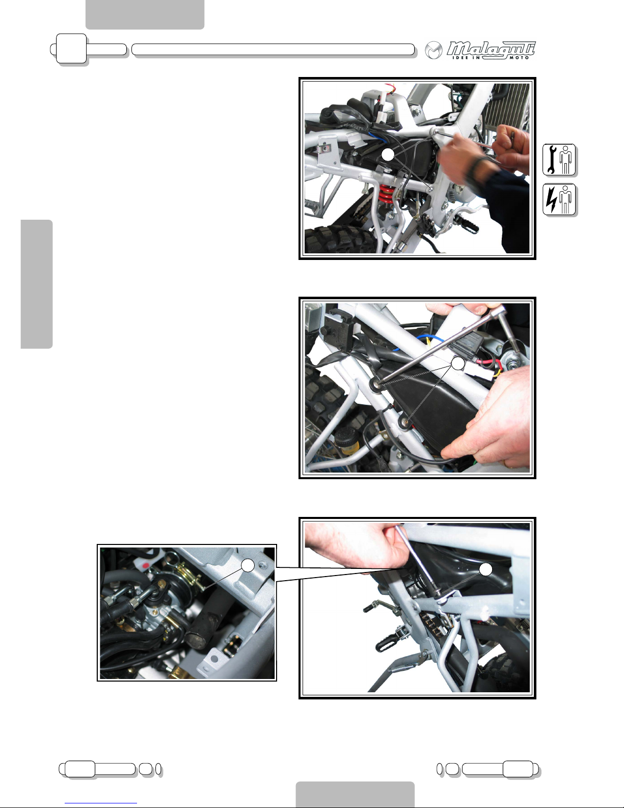
REAR CHASSIS
• (Remove seat, rear side casings, tail section,
shock absorber guard, battery, rear brake fluid
tank,regulator, flashlight and silencer).
Undo the screws (V4 - F.19).
AIR FILTER SUCTION BOX
• (Remove seat, rear side casings, tail section,
battery, rear wing, silencer and rear chassis).
Undo the screws (V3 - F.20 - F.21) and loosen the
clamp (F - F.21b).
Page 27
A
05.03 27
CHAPTER
PAGEISSUE
CHASSIS
ENGLISH
SECTION 2
Disassembly XTM - XSM
SECTION 3
A - CHASSIS
F.22
V2
F.23
V
F.24
V2
F.24b
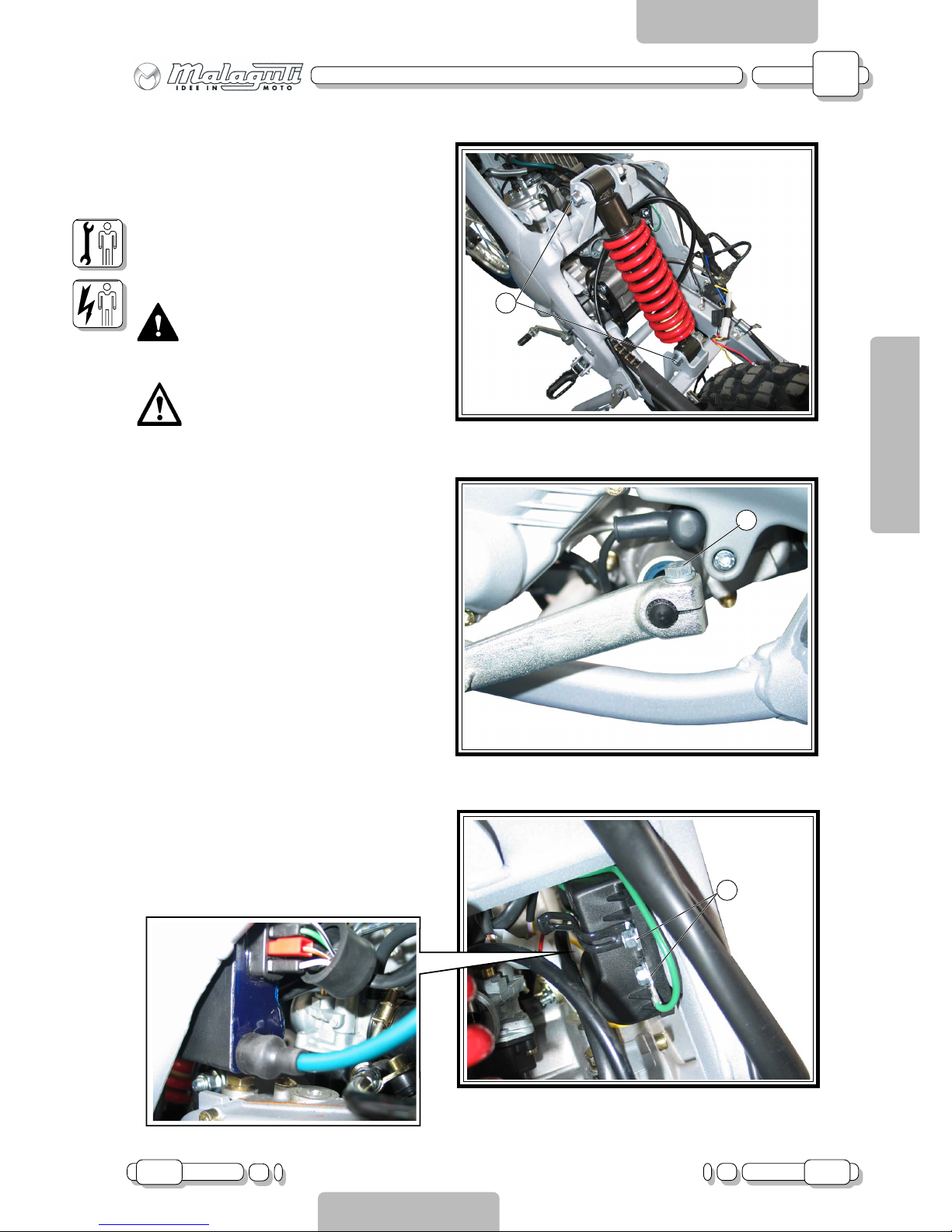
SHOCK ABSORBER
• (Remove the seat, rear left hand casing).
Undo the two screws holding the tank in place on
the rear side, and remove the rubber protection.
Undo the screws (V2 - F.22) and remove the shock
absorber.
CAUTION!!!
Before disassembly, hold the centre
chassis section to prevent the vehicle
falling over.
Caution!!! Check the direction in
which you are fitting the shock absorber and tighten the screws (V2) to
the established torque setting.
SHIFT LEVER
Undo the screw (V - F.23) and remove the lever.
CONTROL UNIT
• (Remove seat and rear right hand casing)
Undo the self-tapping screws (V2 - F.24), detach
the cables and spark plug cap and remove the
control unit.
Page 28
A
28 05.03
CHAPTER
PAGE ISSUE
CHASSIS
ENGLISH
SECTION 2
Disassembly XTM - XSM
SECTION 3
A - CHASSIS
F.25
F.27
V2
L
F.26
P
F
C
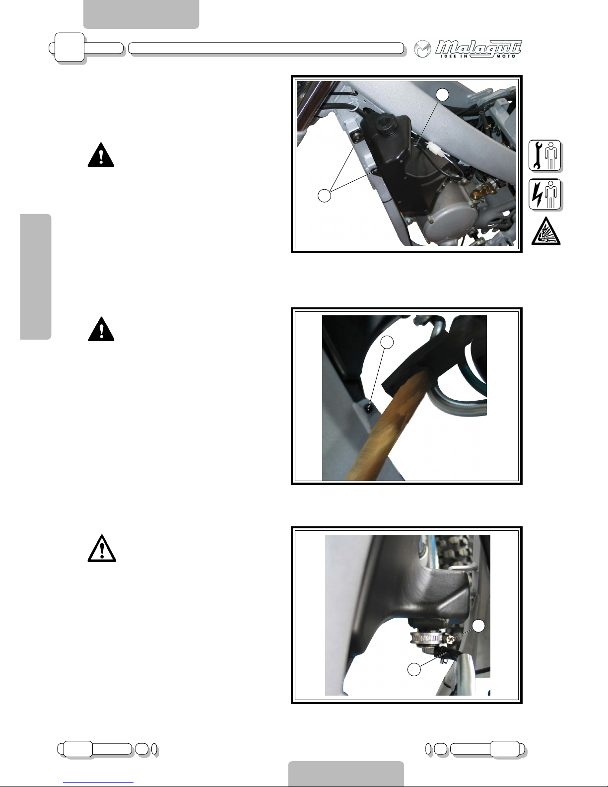
OIL TANK
• (Remove seat and front left conveyor).
CAUTION!!!
Empty the tank before disassembly; to
do so:
1. Put a pan under the oil tank.
2. Remove the pipe clamp (F - F.27)
and detach the pipe from its fitting.
Undo the screws (V2 - F.25), detach the
probe connector (C - F.25) and release the tank
pin (P - F.26) from the chassis.
OIL LEVEL PROBE
CAUTION!!!
Before removing the probe, release
the tank from the chassis.
Detach the probe’s connector (C - F.25) from the
main wiring.
OIL PIPE FITTING WITH FILTER
Caution!!! Before removing the fitting,
release the tank from the chassis.
Loosen the clamp (L - F.27) and remove the fitting,
paying attention not to damage the O-ring.
Page 29
A
05.03 29
CHAPTER
PAGEISSUE
CHASSIS
ENGLISH
SECTION 2
Disassembly XTM - XSM
SECTION 3
A - CHASSIS
F.28
V2
V
F.28b
B
D
S
F
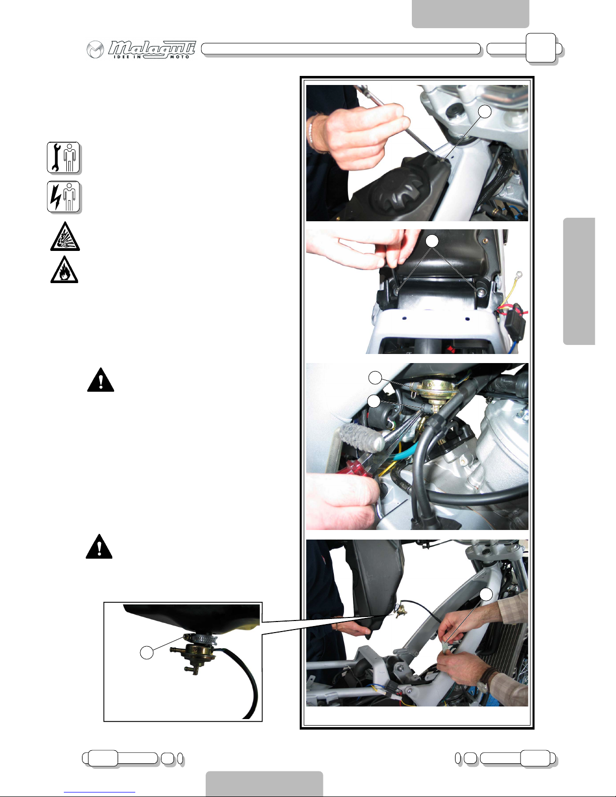
FUEL TANK
• (Remove seat and top screw of the front con-
veyors)
Undo the front fixing screw (V - F.28) and the rear
fixing screws (V2 - F.28).
Disconnect the vacuum pipe (D - F.28) and the
petrol pipe (B - F.28) from the fuel cock.
Raise the tank and detach the fuel probe connector (S - F.28)
CAUTION!!!
Empty the tank.
FUEL COCK
• (Remove seat and fuel tank)
CAUTION!!!
Make sure the tank is empty.
Loosen the clamp (F - F.28b) and remove the cock.
Page 30
A
30 05.03
CHAPTER
PAGE ISSUE
CHASSIS
ENGLISH
SECTION 2
Disassembly XTM - XSM
SECTION 3
A - CHASSIS
F.29
F.30
V2
P
F.31
S
T
T
C
G
V2
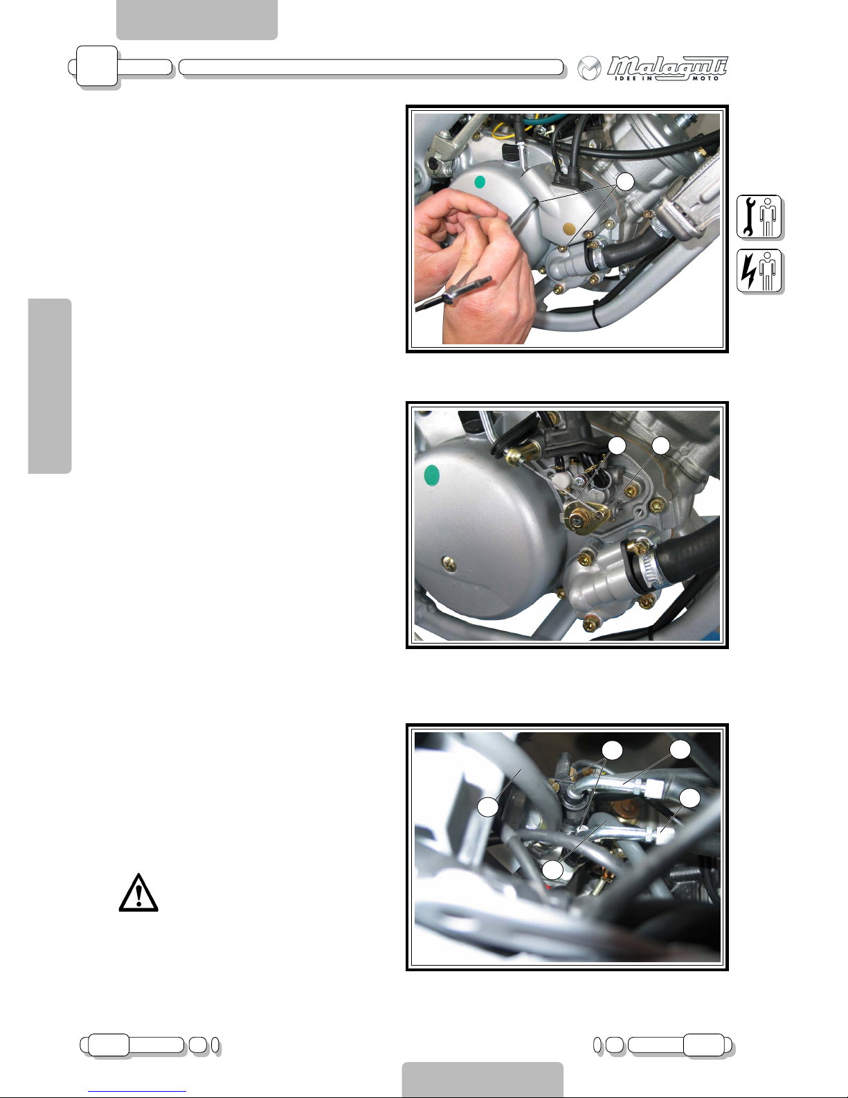
THROTTLE CABLE / MIXER
Undo the screws (V2 - F.29) and remove the pump
cover.
Release the cable (C - F.30) from the pump body
(P - F.30).
CARBURETTOR
• (Remove seat, side casings, fuel tank)
Remove the throttle cable coupler (G - F.31) and
the starter coupler (S - F.31), by loosening the
screws (V2 - F.31).
Remove the pipe clamps and detach the pipes (T F.31).
Detach the carburettor from the suction manifold,
after loosening the spring.
Caution!!! If you are removing the engine only, the carburettor can be left
attached to the engine.
Page 31
A
05.03 31
CHAPTER
PAGEISSUE
CHASSIS
ENGLISH
SECTION 2
Disassembly XTM - XSM
SECTION 3
A - CHASSIS
F.32
F.33
B
L
V
V3
F.34
P
RF
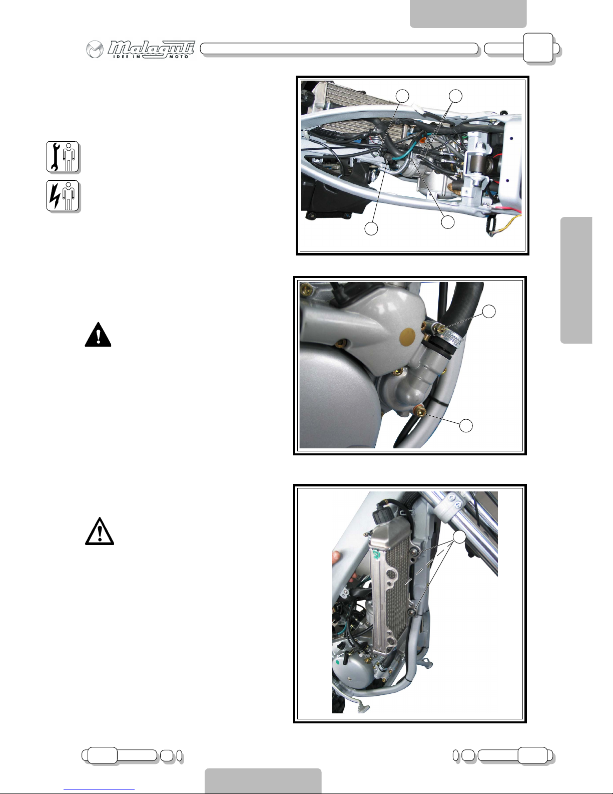
ENGINE
• (Remove seat, tank, side conveyors and muf-
fler)
Detach the two pipes of the cylinder head heater
(R - F.32), remove the suction manifold screws and
detach the spark plug cap (P - F32).
Detach the white/green cable from the thermistor
(F - F.32).
Detach the neutral cable (under the engine, near
the shift levers) and the cables of the flywheel and
control unit, releasing them from their clamps.
Remove the mixer cover and disconnect the transmission. Remove the mixer pump by loosening the
two Allen screws.
Empty the coolant circuit by means of the drainage screw on the pump body (V - F.33).
Remove the head-radiator (B - F.32) and pumpradiator (L - F.33) couplings.
Remove the pinion cover.
CAUTION!!!
Before disassembly, hold the centre
chassis section to prevent the vehicle
falling over.
Remove the lock nut and pull out the fork pin.
Loosen the nut of the front engine pin and remove
the pin.
Pull the engine out from the left hand side, by first
pulling out the front section.
RADIATOR
• (Remove seat and right hand conveyor)
Caution!!! Before removing the radiator, drain the coolant using the drain
screw on the pump cover (V - F.33).
Undo the screws (V3 - F.34) and remove the radiator.
Page 32
A
32 05.03
CHAPTER
PAGE ISSUE
CHASSIS
ENGLISH
SECTION 2
Disassembly XTM - XSM
SECTION 3
A - CHASSIS
F.35
M
V
F.37
V4
V4
F.36
V
V1
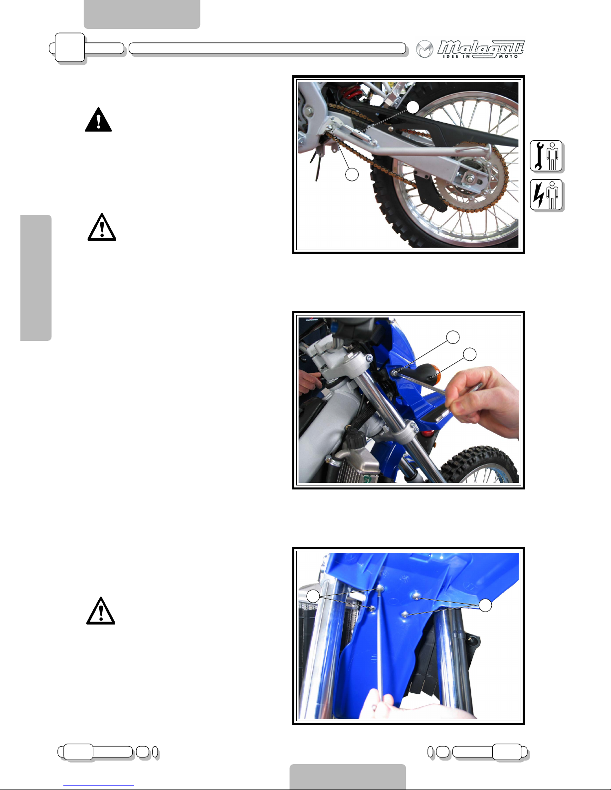
SIDE STAND
CAUTION!!!
Before disassembly, hold the centre
chassis section to prevent the vehicle falling over.
This operation must be performed
with the side stand in its idle position.
Release the screws (M - F.35) and undo the screw
(V - F.35).
Caution!!! When reassembling, use a
high strength threadlocker.
FRONT INDICATORS (right and left)
Undo the screw (V - F.1).
Remove the glass cover and detach the lamp socket cables.
Undo the fixing screw (V - F. 36).
GUARD / FRONT WING
• (Remove front indicators)
Undo the screws (V4 - F.37) of the front wing.
Caution!!! Remember to retrieve the
bearings in the bottom section.
Page 33
A
05.03 33
CHAPTER
PAGEISSUE
CHASSIS
ENGLISH
SECTION 2
Disassembly XTM - XSM
SECTION 3
A - CHASSIS
F.38
A
L2
C
G
P
F.39
V2
C
C
V2a
M
V2
R
F.40
I
H
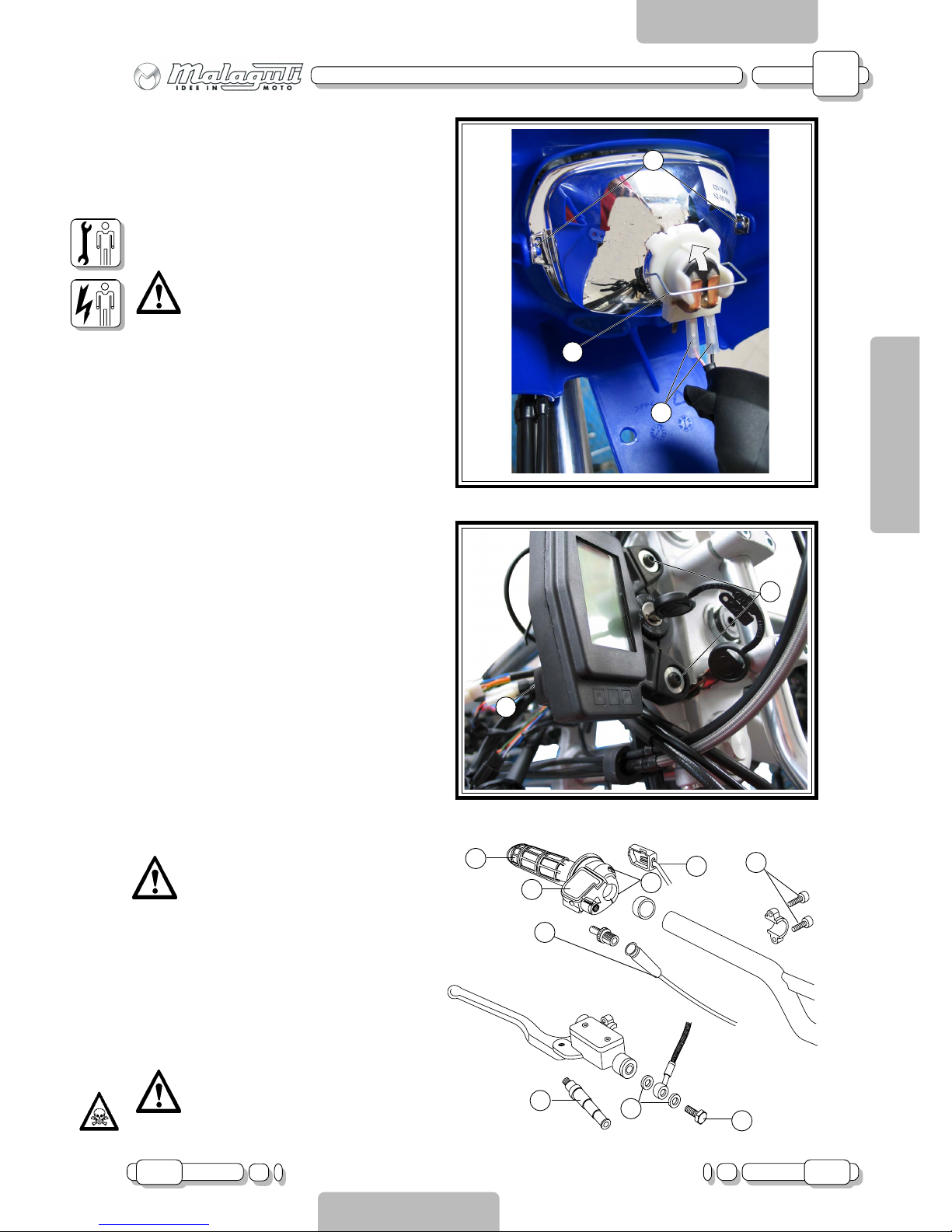
HEADLIGHT
• (Remove guard)
Remove the fast-ons of the wiring (A - F.38) and
remove the headlight by folding the tabs outwards
(L2 - F.38).
To access the lamp, open the clip (C - F.38).
Caution!!! When reassembling, pay
attention to the fast-on assembly sequence (see wiring diagram).
DISPLAY
• (Remove the front indicators and guard)
Detach the connector (C - F.39) and unscrew the
fixing screws (V2 - F.39).
THROTTLE CONTROL
Remove the MODE button (P - F.40), by unscrewing the fixing screw.
Remove the front cover (C - F.40) and release the
throttle cable (G - F.40).
Remove the knob (M - F.40).
Undo the screws (V2 - F.40) and remove the throttle control.
Caution!!! To reduce friction during
knob removal and refitting, use compressed air.
FRONT BRAKE PUMP
Detach the fast-ons of the stop switch wiring (I F.40). Undo the hydraulic transmission screw (R F.40), paying attention to oil leaks.
Loosen the screws (V2a - F.40) and remove the
pump.
CAUTION!!!
When refitting, remember to replace
the copper gaskets (H - F.40) and bleed
using the relevant equipment.
Page 34
A
34 02.04
CHAPTER
PAGE ISSUE
CHASSIS
ENGLISH
SECTION 2
Disassembly XTM - XSM
SECTION 3
A - CHASSIS
V2b
S
F
V2a
F.41
F.42
V4
F.43
V2
V
T
A
L
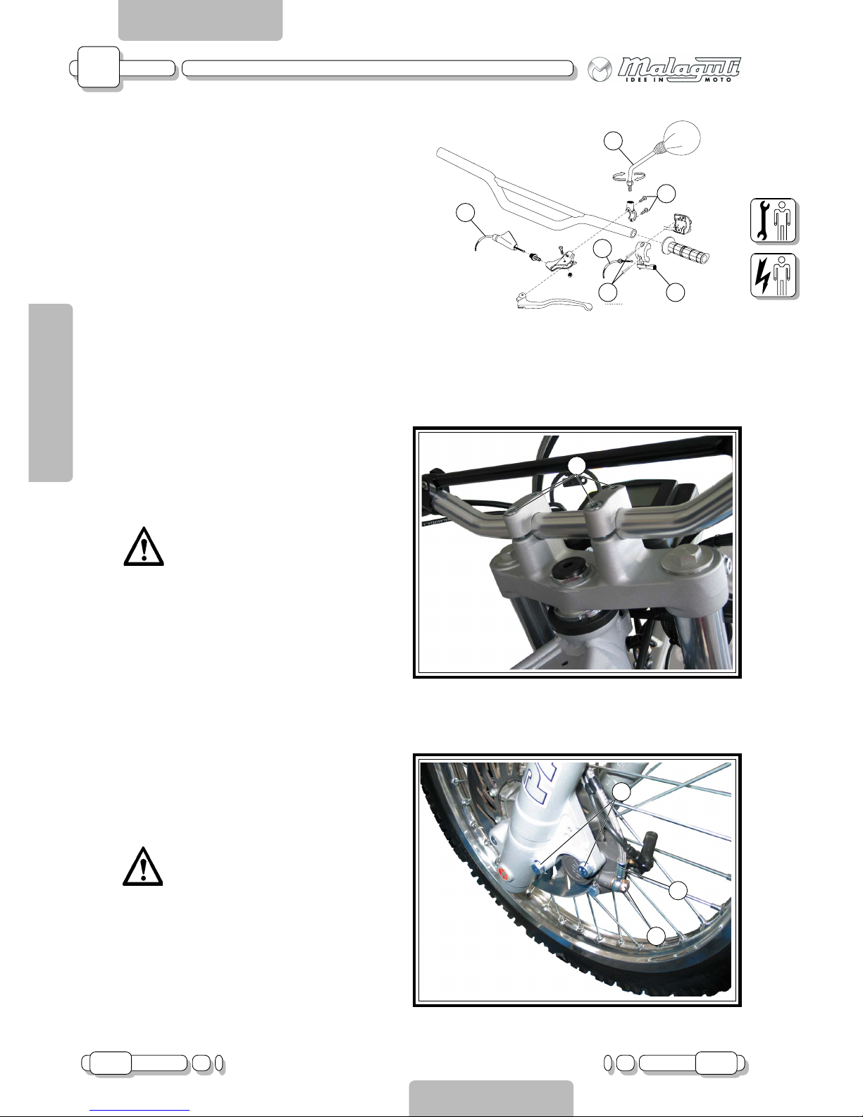
CLUTCH CONTROL
Detach the clutch cable (F - F.41) and the starter
cable (S - F.41) and remove the mirror (A - F.41).
Loosen the screws (V2b - F.41), remove the starter lever body (L - F.41) and the left hand knob.
Loosen the screws (V2a - F.41) and remove the
left hand control.
HANDLEBAR
• (Remove right and left controls)
Loosen the screws (V4 - F.42), to remove the Ubolts holding the handlebar in place.
Caution!!! When refitting, remember
to tighten the front screws first.
FRONT BRAKE CALIPER
Loosen the screws (V2 - F.43) and disconnect the
pipe (T - F.43), after loosening the hydraulic transmission screw (V - F.43).
Caution!!! When refitting, remember to
replace the copper gaskets and bleed
using the relevant equipment.
Page 35
A
02.04 35
CHAPTER
PAGEISSUE
CHASSIS
ENGLISH
SECTION 2
Disassembly XTM - XSM
SECTION 3
A - CHASSIS
F.43A
F.43B
F.44
V
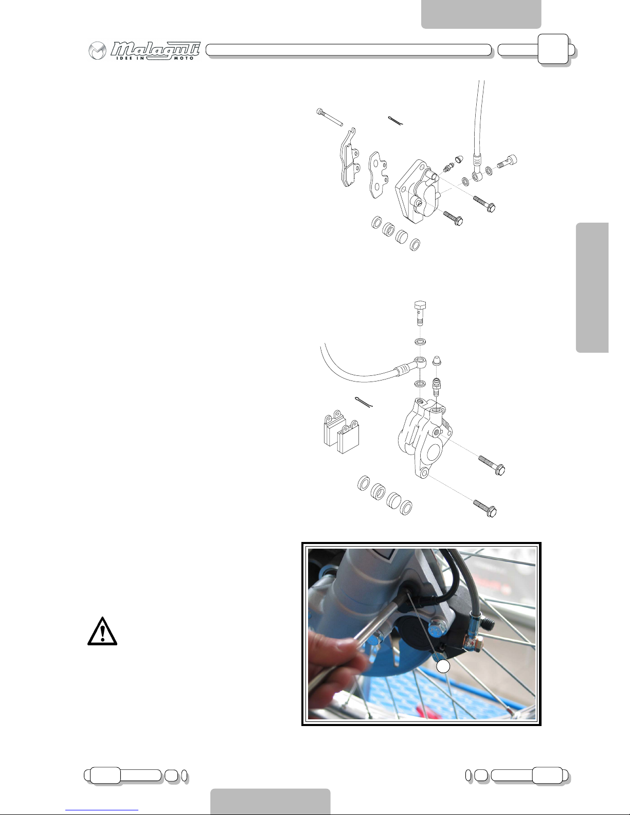
SPEEDOMETER SENSOR
Loosen the screw (V - F.44) and remove the sensor; release the cable from the U-bolts and detach
the connector under the headlight.
Caution!!! When refitting, pay attention
to the shim washer between the sensor and the fork.
REMOVING THE FRONT BRAKE CALIPERS
(ENDURO model).
.
REMOVING THE FRONT BRAKE CALIPERS
(MOTARD model).
Page 36
A
36 02.04
CHAPTER
PAGE ISSUE
CHASSIS
ENGLISH
SECTION 2
Disassembly XTM - XSM
SECTION 3
A - CHASSIS
F.45
P
F.46
V6
V2
F.45b
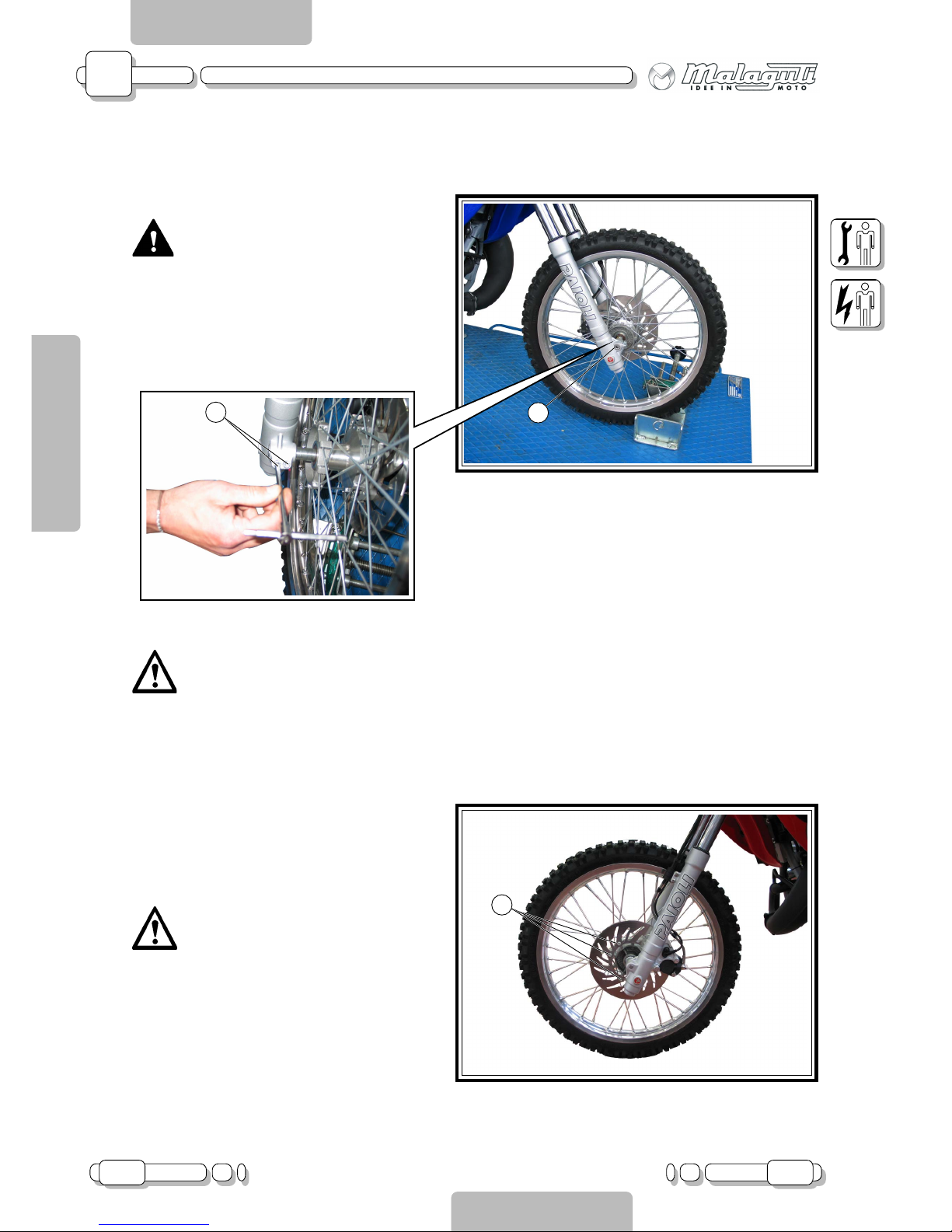
FRONT WHEEL
• (Remove front caliper and speedometer sensor)
CAUTION!!!
Before disassembly, hold the centre
chassis section to prevent the vehicle
falling over.
Loosen the screw (V2 - F.45b).
Unscrew the pin (P - F.45) and remove it.
Remove the front wheel.
Caution!!! When refitting, after tightening the pin (P - F.45), remember to the
tighten the screws (V2 - F.45b).
FRONT BRAKE DISC
• (Remove front wheel)
Loosen the screws (V6 - F.46)
Caution!!! When refitting, use threadlocker.
Page 37
A
02.04 37
CHAPTER
PAGEISSUE
CHASSIS
ENGLISH
SECTION 2
Disassembly XTM - XSM
SECTION 3
A - CHASSIS
F.47
F.48
G
P
C
D
V2
P
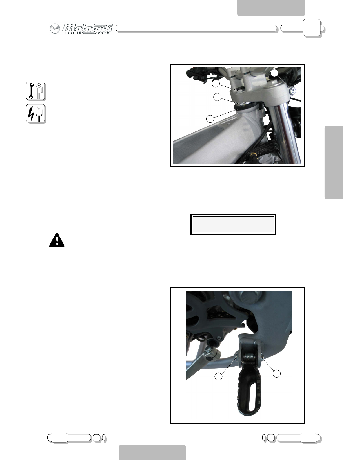
FORK HEAD
• (Remove front indicators, guard, digital instru-
ment board and handlebar)
Unscrew the Allen screws (V2 - F.47)
Unscrew the nut (D - F.47) and remove the fork
head.
FORK
• (Remove front indicators, guard, digital instru-
ment board, front wheel, speedometer sensor, front
caliper, handlebar and fork head)
Unscrew the ring nut (G - F.47), remove the dust
guard (P - F.47) and pull out the fork.
CAUTION!!!
Before disassembly, hold the centre
chassis section to prevent the vehicle
falling over.
FOOT RESTS (right and left)
Remove the split pin (C - F.48), pull out the pin (P
- F.48) and remove the spring.
Amount of oil per stem: 350cc.
Page 38
A
38 02.04
CHAPTER
PAGE ISSUE
CHASSIS
ENGLISH
SECTION 2
Disassembly XTM - XSM
SECTION 3
A - CHASSIS
F.49
F.50
F.51
V
P
A
A
V
V
2
F
I
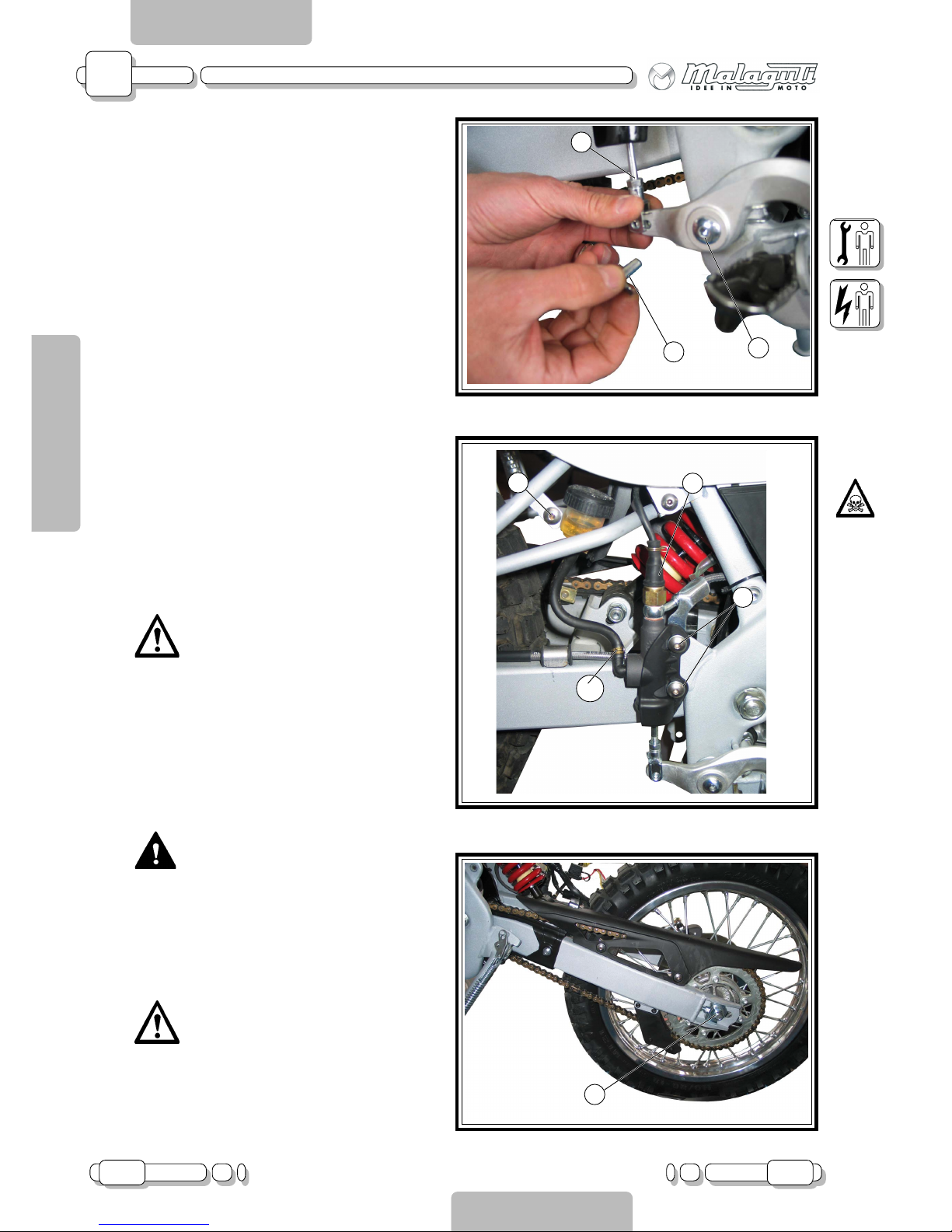
REAR BRAKE LEVER
Remove the stick (A - F.49), by pulling out the pin
(P - F.49); loosen the screw (V - F.49) and remove:
the pedal, the spring, the bushing and the plastic
washer.
REAR BRAKE PUMP AND REAR BRAKE OIL
TANK
Remove the clamp (F - F.50) and empty the contents of the oil circuit into a container. Loosen the
screw (V - F.50) and remove the rear brake oil tank.
To remove the pump: disconnect the cable from
the rear stop switch (I - F.50) and unscrew it. Undo
the fixing screws (V2 - F50), paying attention to
the eye adjustment plaque.
Caution!!! When refitting, remember
to replace the copper gaskets and
bleed using the relevant equipment.
REAR WHEEL
CAUTION!!!
Before disassembly, hold the centre
chassis section to prevent the vehicle
falling over.
Unscrew the nut (A - F.51), loosen the chain tightening adjusters, release the chain from the gear
wheel and remove the pin (P - F.52).
Caution!!! When refitting, follow the
instructions provided in section 2, in
“ADJUSTING TRANSMISSION CHAIN
TIGHTNESS”
Page 39
A
02.04 39
CHAPTER
PAGEISSUE
CHASSIS
ENGLISH
SECTION 2
Disassembly XTM - XSM
SECTION 3
A - CHASSIS
T
V
F.52
T
P
F.52A
V3
F.53
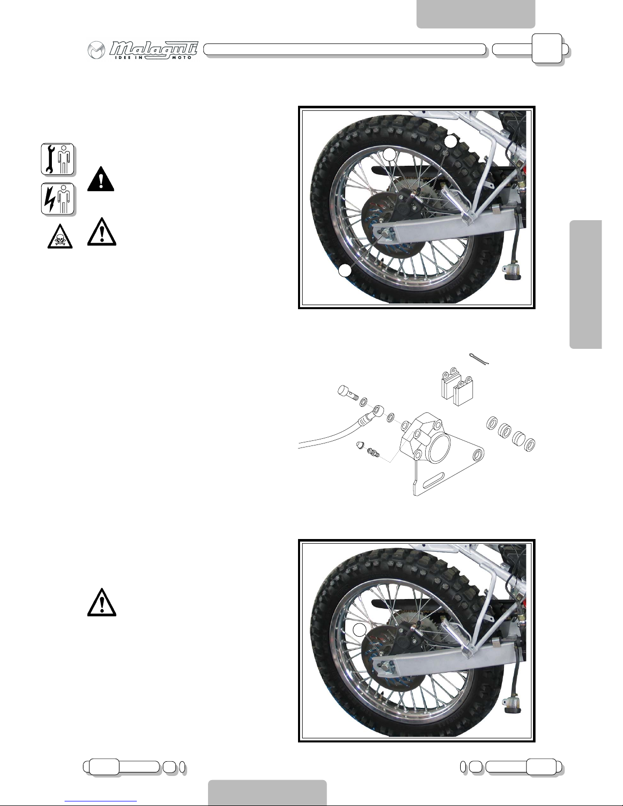
REAR BRAKE CALIPER
• (Remove rear wheel)
Loosen the hydraulic transmission screw (V - F.52)
and detach the pipe (T - F.52) from the caliper.
Release the calipers from the fork.
CAUTION!!!
Before disassembly, hold the centre
chassis section to prevent the vehicle
falling over.
Caution!!! When refitting, remember to
replace the copper gaskets and bleed
using the relevant equipment.
REAR DISC BRAKE
• (Remove front wheel and rear caliper)
Undo the screws (V3 - F.53).
Caution!!! When refitting, use thread-
locker.
REMOVING THE REAR BRAKE CALIPERS
(MOTARD/ENDURO model).
Page 40
A
40 02.04
CHAPTER
PAGE ISSUE
CHASSIS
ENGLISH
SECTION 2
Disassembly XTM - XSM
SECTION 3
A - CHASSIS
F.55
D
F.54
V
3
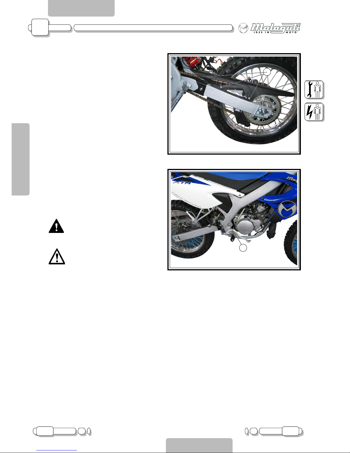
CHAIN CRANKCASE
Undo the screws (V3 - F.54).
FORK
• (Remove rear wheel, rear brake caliber, shock
absorber, chain crankcase)
Unscrew the nut (D - F.55) and remove the pin.
CAUTION!!!
Before disassembly, hold the centre
chassis section to prevent the vehicle
falling over.
Caution!!! When refitting, follow the instructions provided in section 2, in “ADJUSTING TRANSMISSION CHAIN
TIGHTNESS”
Page 41
A
05.03 41
CHAPTER
PAGEISSUE
CHASSIS
ENGLISH
SECTION 2
Assembly XTM - XSM
SECTION 4
A - CHASSIS
G
G
G
G
3.8 - 5.2
1.7 - 2.3
2.4 - 3.6
0.6 - 1.0
2.0 - 2.6
5.1 - 6.9
2.0 - 2.6
0.5 - 0.7
7.2 - 9.8
0.2 - 0.4
3.8 - 5.2
3.8 - 5.2
1.8 - 2.4
1.8 - 2.4
2.5 - 3.4
1.6 - 2.4
0.6 - 1.0
38 - 52
17 - 23
24 - 36
6 - 10
20 - 26
51 - 69
20 - 26
5 - 7
72 - 98
2 - 4
38 - 52
38 - 52
18 - 24
18 - 24
25 - 34
16 - 24
6 - 10
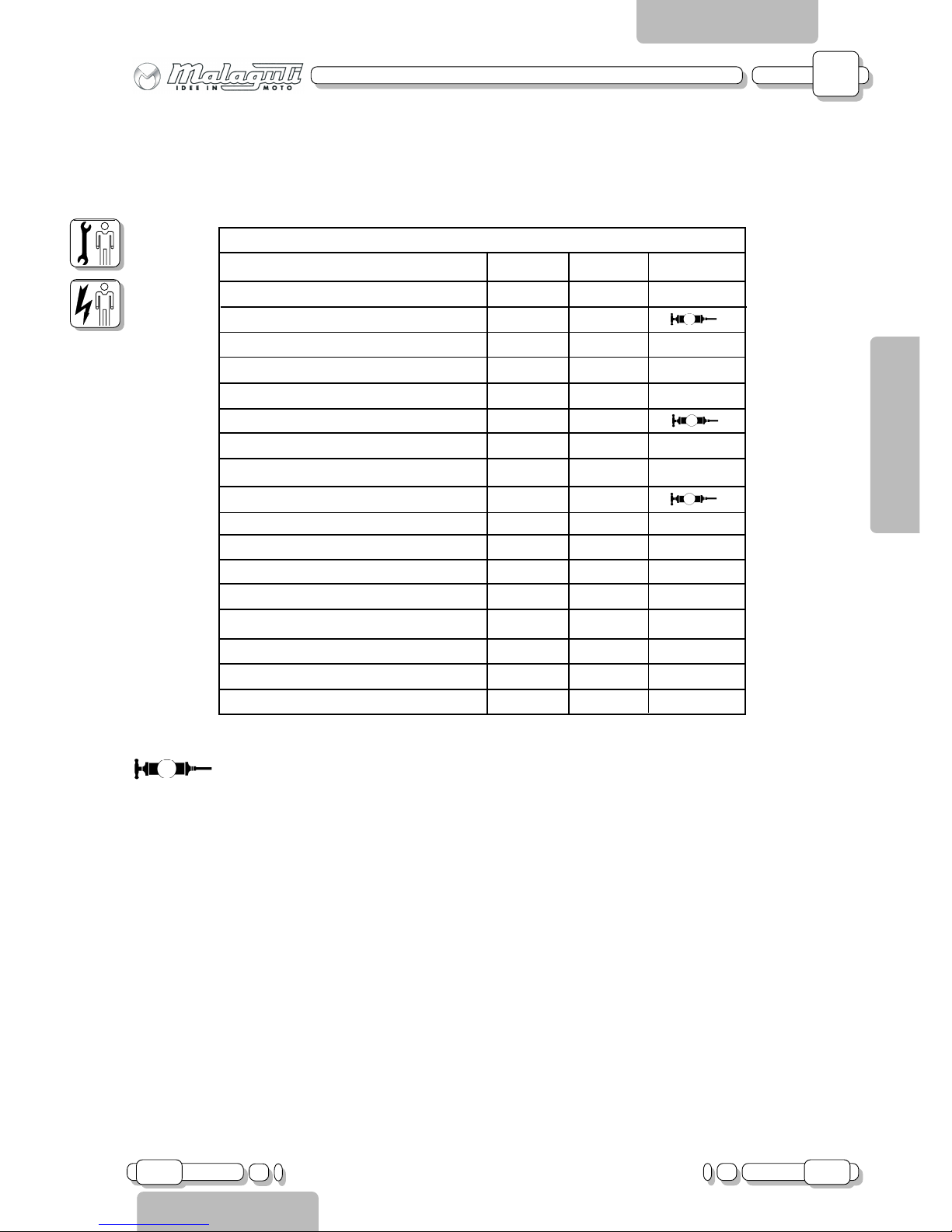
CHASSIS TORQUE WRENCH SETTINGS
Greasing (grease)
TORQUE WRENCH SETTINGS TABLE
TOURQUE WRENCH SETTINGS N*m Kg*m Remarks
Front wheel pin
Front wheel pin fixing element
Front brake caliper
Muffler side coupler
Rear engine fixing screws
Fork pin
Front engine fixing screws
Front pump clamp
Rear wheel
Clamps
Top shock absorber
Bottom shock absorber
Fork head
Handlebar U-bolt
Steering nut
Rear frame
Silencer
Page 42
A
42 05.03
CHAPTER
PAGE ISSUE
CHASSIS
ENGLISH
SECTION 2
Disassembly XTM - XSM
SECTION 3
A - CHASSIS
 Loading...