

Page 1
Page 2
2 03/09
125 - 160 cc
BlogBlog
BlogBlog
Blog
MALAGUTI S.p.A.
Via Emilia 498, 40068 - San Lazzaro di Savena (BO) - ITALY
Tel. 051.62.24.811 - Fax 051.69.47.782
e-mail: info@malaguti.com - http: // www.malaguti.com
FOREWORD
• This manual specifically addresses to specialised technical personnel (MALAGUTI authorised service centres and single motor mechanics) and contains all the
service interventions indicated by the Manufacturer until the publishing of this document.
• Some basic technical information has been intentionally omitted as it is considered to be common knowledge.
• Additional information is available in the SPARE PARTS CATALOGUES of each model.
• It is important to read all the general information before going through the manual to the specific topics and the maintenance operations to be carried out on the motor-bike in
order to make sure the topics, the technical and safety concepts are clearly understood and the manual can be used as a sure reference text.
• All checks, maintenance, repairs or replacements of spare parts in our motor-bikes are to be performed by skilled and expert technical personnel with specific experience
in state-of-the-art technology and full knowledge of the quickest and most rational procedures, technical characteristics, setting values, tightening torques and information as
to which may only be properly and exhaustively provided by the manufacturer.
• It is important to adhere strictly to the following instructions. Any operation carried out carelessly or not carried out at all may lead to personal injury, damage to the motorcycle
or simply to complaints.
MALAGUTI S.p.A. reserves the right to make any changes and modifications hereto it deems necessary without prior notice.
For further information and details, please contact MALAGUTI S.p.A. Servicing or Engineering Division.
Page 3

3 03/09
125 - 160 cc
BlogBlog
BlogBlog
Blog
NOTES FOR EASY CONSULTATION
ABBREVIATIONS
EDITING SYMBOLS:
• Symbols have been provided for quick and easy reference, identifying situations requiring utmost attention or providing practical suggestions or simple information.
• These symbols may appear next to a text (in which case they refer solely to the text itself), next to a figure (in which case they refer to the topic illustrated in the figure and
to the relative text), or at the top of the page (in which case they refer to all the topics dealt with in the page).
NOTE - The meaning of the symbols should be duly memorised as their scope is to avoid having to repeat basic technical concepts or safety recommendations.
Cs Torque wrench setting
D Nut
Dx Right
F Picture
G Gasket
P Page
R Washer
Sx Left
T Ta b l e
V Screw
TECHNICAL DICTIONARY
V = (DC) Direct current (battery supply)
V ~ (AC) Alternating current (flywheel supply)
A : Ampere Unit of measurement of the electrical current
W : Watt Unit of measurement of the electrical power (product of Volts and Amperes; A x V = W)
ΩΩ
ΩΩ
Ω : OHM Unit of measurement of the electrical resistance
< Lower
≤≤
≤≤
≤ Lower or equal
> Higher
≥≥
≥≥
≥ Higher or equal
bar Unit of measurement of pressure
N * m Newton/metre Unit of measurement of the tightening torque
Page 4
4 03/09
125 - 160 cc
BlogBlog
BlogBlog
Blog
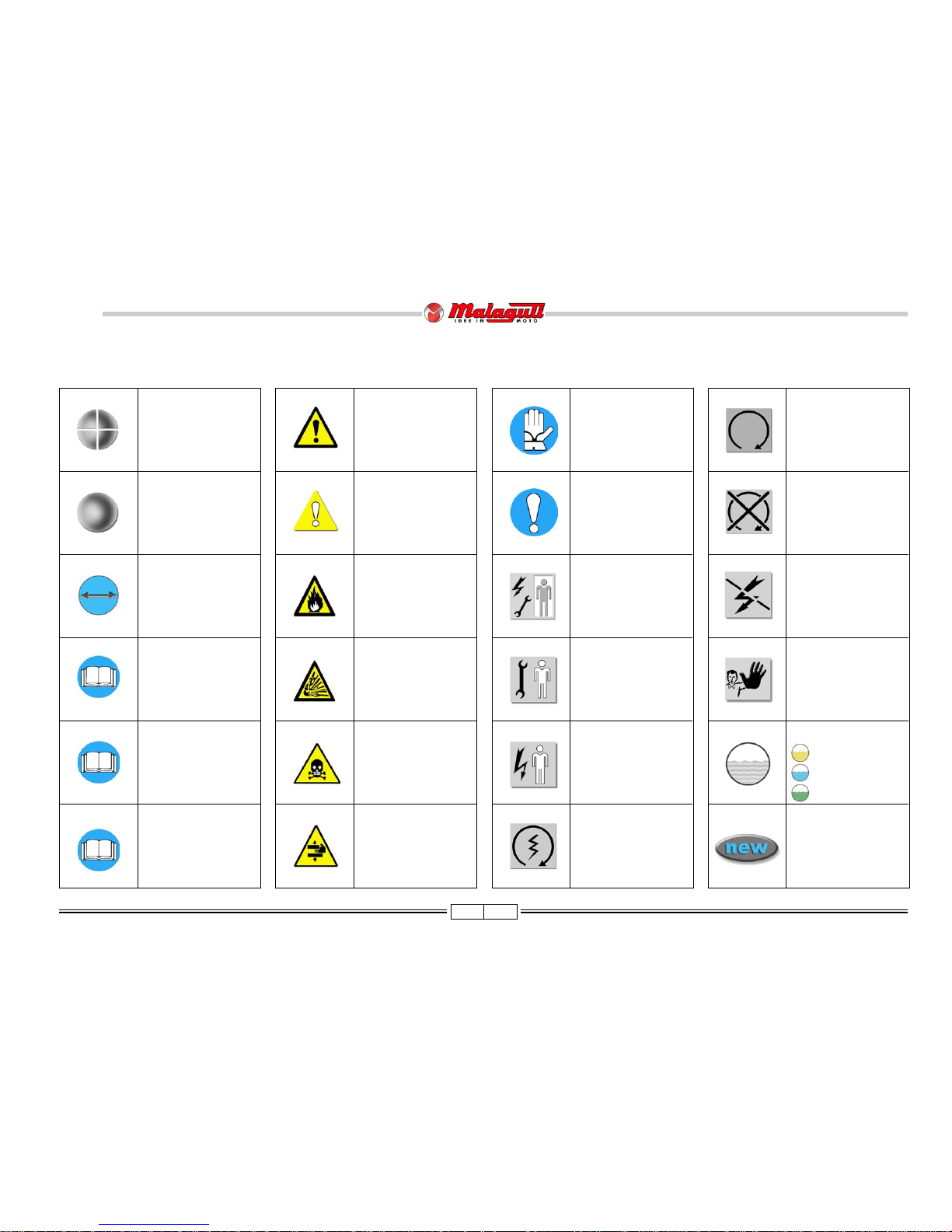
SYMBOL LIST
M
R
CAUTION!
Recommendations and
precautions regarding rider
safety and motor vehicle
integrity.
WARNING! Situations
entailing the risk of personal
injury to maintenance or repair
mechanics, other workshop
personnel or third parties, or
damage to environment,
vehicle or equipment
FIRE HAZARD.
Indicates operations which
may constitute a fire
hazard
RISK OF
EXPLOSION
Indicates operations
which may constitute a
risk of explosion
TOXIC FUMES
Indicates a possibility of
intoxication or inflammation
of the upper respiratory
tract
WARNING!
Danger of crashing
arms
SAFETY GLOVES
These operations require
the use of safety gloves
IMPORTANT
This topic requires special
attention
GENERAL SERVICE
PERSONNEL
Skilled electronic or
mechanical technician.
MECHANICAL
MAINTENANCE
Operations to be
performed only by an
expert mechanic
ELECTRICAL
MAINTENANCE
Operations be performed
only by an expert electrical/
electronic technician
IGNITION KEY ON
(ON position)
THIS MANUAL
Information on
this manual
“ENGINE” SERVICE
MANUAL
Indicates information which
may be obtained by
referring to said catalogue
SPARE PARTS
CATALOGUE
Indicates information which
may be obtained by
referring to said catalogue
DISASSEMBLY
OPERATIONS
ASSEMBLY
OPERATIONS
SYMMETRICAL
OPERATIONS
Operations that must be
carried out also on the other
side of the unit or
component.
EMPTY THE CIRCUIT
REPLACE WITH NEW,
ORIGINAL SPARE
PAR TS
IDLING ENGINE
Switch on the engine, at
idling speed, to perfom
these interventions.
ENGINE OFF
Indicates operations to
be performed with
engine off
POWER OFF
Indicates that negative
pole is to be disconnected
from the battery before
performing the operation
NO!
Operations to be
absolutely avoided
OIL
COOLANT
FUEL
Page 5
5 03/09
125 - 160 cc
BlogBlog
BlogBlog
Blog
GENERAL WORK PROCEDURES
• The recommendations given hereafter are aimed at ensuring maximum work safety as well as at considerably reducing the risk of accidents, personal injury, equipment
damage and idle times, and should therefore be strictly adhered to.
• Always listen with attention to the customer’s opinion and complaints about the motor-bike operation, asking specific questions in order to have a complete understanding of
all the symptoms and identify with good approximation the real causes of the trouble. The present manual provides the technical information and the basic indications on the
intervention procedures but these have to be integrated with the personal expertise.
• We suggest planning the service interventions in order to avoid any waste of time or downtime. Try to reduce as much as possible the operations necessary to reach the
components that needs repairing.
• Prepare the components that are likely to be replaced and all the original spare parts you may need.
• Use only the original spare parts.
• Mark the components that may be mis-placed during re-assembly operations.
• Only use quality tools and equipment.
• Only use equipment conforming to EU Directives for lifting the vehicle.
• During operations, always keep tools and equipment at hand, possibly laying them out according to the sequence in which they are to be used. Absolutely avoid putting them on the
vehicle itself, out-of-sight or in poorly accessible places.
• Always keep the work area neat and clean.
• When tightening screws or nuts, start with the larger diameter or inner fasteners, and tighten them in progressive “pulls” using a “criss-cross” pattern.
• The torque settings specified in the manual refer to the “final torque”, which must be attained progressively by steps.
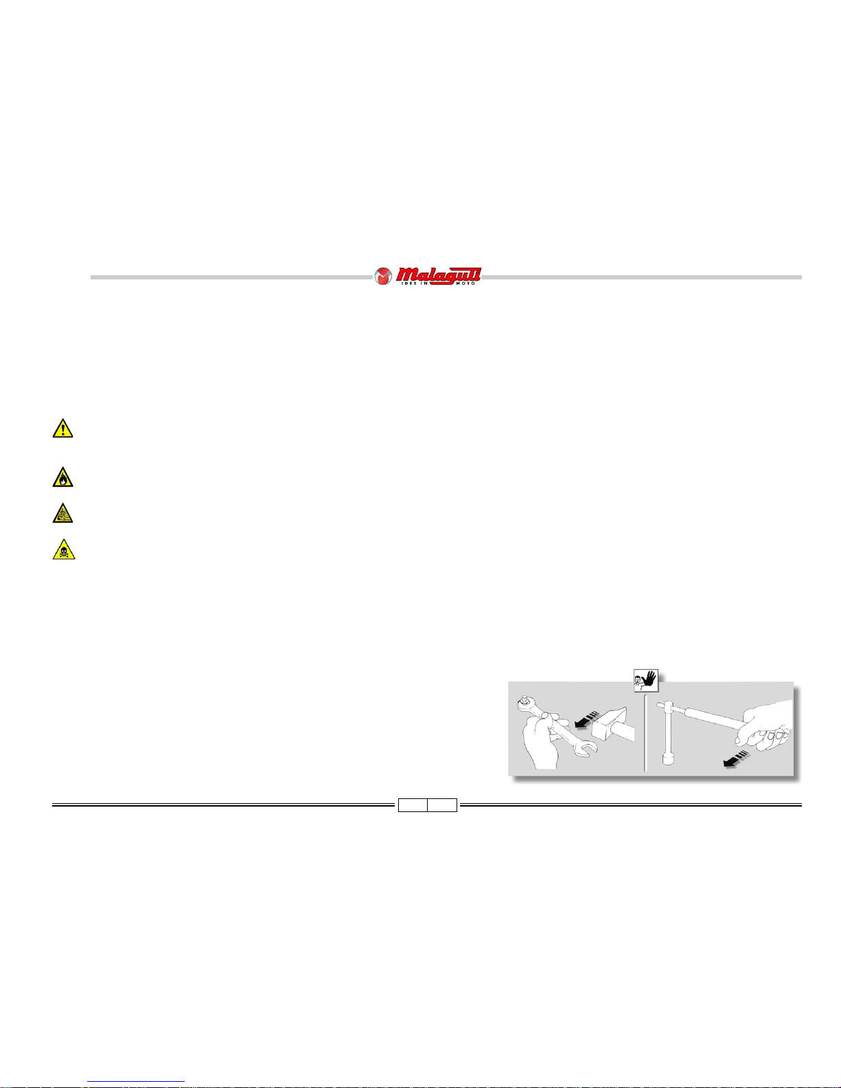
• Preferably use open-end box wrenches by “pulling” and not “pushing”.
Before any servicing, make sure that the vehicle is perfectly stable.
The front wheel should be anchored to fixture, which is integral with the lift platform.
Page 6
6 03/09
125 - 160 cc
BlogBlog
BlogBlog
Blog
• Before carrying out any operation, wait for all parts to cool down.
• For operations requiring two mechanics, make sure that the various steps to be performed by each of them are clearly defined and co-ordinated beforehand.
• Make sure that each component has been properly mounted before proceeding with assembling the next one.
• Always replace gaskets, O-rings, circlips and split pins at every refitting.
• Only use screwdrivers with sizes suitable to the screws to be loosened or tightened.
Never use open flames for any reason.
Never leave open containers or containers not suitable for holding fuel in passageways, close to heat sources, etc.
Never use petrol to clean the vehicle or the floor of the workshop. Always use low flash point solvents to clean the vehicle components.
When welding, make sure that there are no flammable liquids in the vicinity.
Never suck from or blow into the fuel pipe.
Never leave the engine running in closed or poorly ventilated areas.
Do not use fuses with a higher rated capacity than indicated: this may cause severe damages to the electrical system and burn a fire as a conse-quence of short circuit.
• Make sure that the vehicle is stable and not to have to take on awkward working positions.
• Never reuse old gaskets or circlips.
• Never use a screwdriver as a lever or chisel.
• Never use pincers to loosen or tighten screws or nuts because, in addition to not providing a sufficient clamping force, they may also damage the screw head or nut hexagon.
• Never tap the wrench with a hammer or other similar tool to loosen or tighten screws and nuts.
• Never attempt to increase the lever arm by fitting a tube into the wrench.
Page 7
7 03/09
125 - 160 cc
BlogBlog
BlogBlog
Blog
CONTENTS
DESCRIPTION P.
SEAT 36
CENTRAL SECTION UNDER THE SEAT 36
HELMET CASE 38
ACCESS (after removing the helmet compartment) 40
FUEL LEVEL SENSOR 41
FUEL PUMP SENSOR 41
FOOTBAR 42
REAR FAIRING 45
REAR HANDLE 45
TAIL LIGHTS 46
FULL REAR FAIRING- FAIRING BREAKDOWN 47
SEAT LOCK UNIT 48
FUEL TANK 51
ELECTRIC FAN AND RADIATOR 52
DISASSEMBLING RADIATOR UNIT - COOLING SYSTEM DRAINAGE 53
FRONT WHEEL 54
FRONT BRAKE DISC 54
FRONT BRAKE CALIPER 55
FRONT MUD GUARD 55
HANDELBAR CONTROL - BRAKE PUMP 56
KEYSWITCH 56
HANDLEBAR 57
FORK 57
FORK LEG 57
COMPLETE FORK 58
MUFFLER 58
MANIFOLD EXHAUST 59
REASSEMBLY OF EXHAUST SYSTEM 59
SHOCK ABSORBERS 60
REAR MUDGUARD - REAR BRAKE CALIPER 61
REAR WHEEL 62
REAR BRAKE DISK 63
STARTER 63
FILTER BOX UNIT 64
AIR FILTER 66
SIDE STAND - CENTRAL STAND 67
ENGINE 67
FRAME SIZE CHECK 68
POSITION OF INJECTION SYSTEM PARTS 69
CABLE POSITIONING, "PIPE SYSTEM" AND ANCHORING TIES 72
2
3
2
3
2
3
2
3
2
3
2
3
2
3
2
3
2
3
2
3
2
3
2
3
2
3
2
3
2
3
2
3
2
3
2
3
2
3
2
3
2
3
2
3
2
3
2
3
2
3
2
3
2
3
2
3
2
3
2
3
2
3
2
3
2
3
2
3
2
3
2
3
2
3
2
3
2
3
2
3
2
3
2
3
2
3
2
3
2
3
2
3
2
3
2
3
2
3
2
3
2
3
2
3
2
3
2
3
2
3
2
3
2
3
2
3
2
3
2
3
2
3
2
3
2
3
2
3
2
3
2
3
2
3
2
3
2
3
2
3
2
3
2
3
2
3
2
3
2
3
2
3
2
3
2
3
2
3
2
3
2
3
2
3
2
3
2
3
2
3
2
3
2
3
2
3
2
3
2
3
2
3
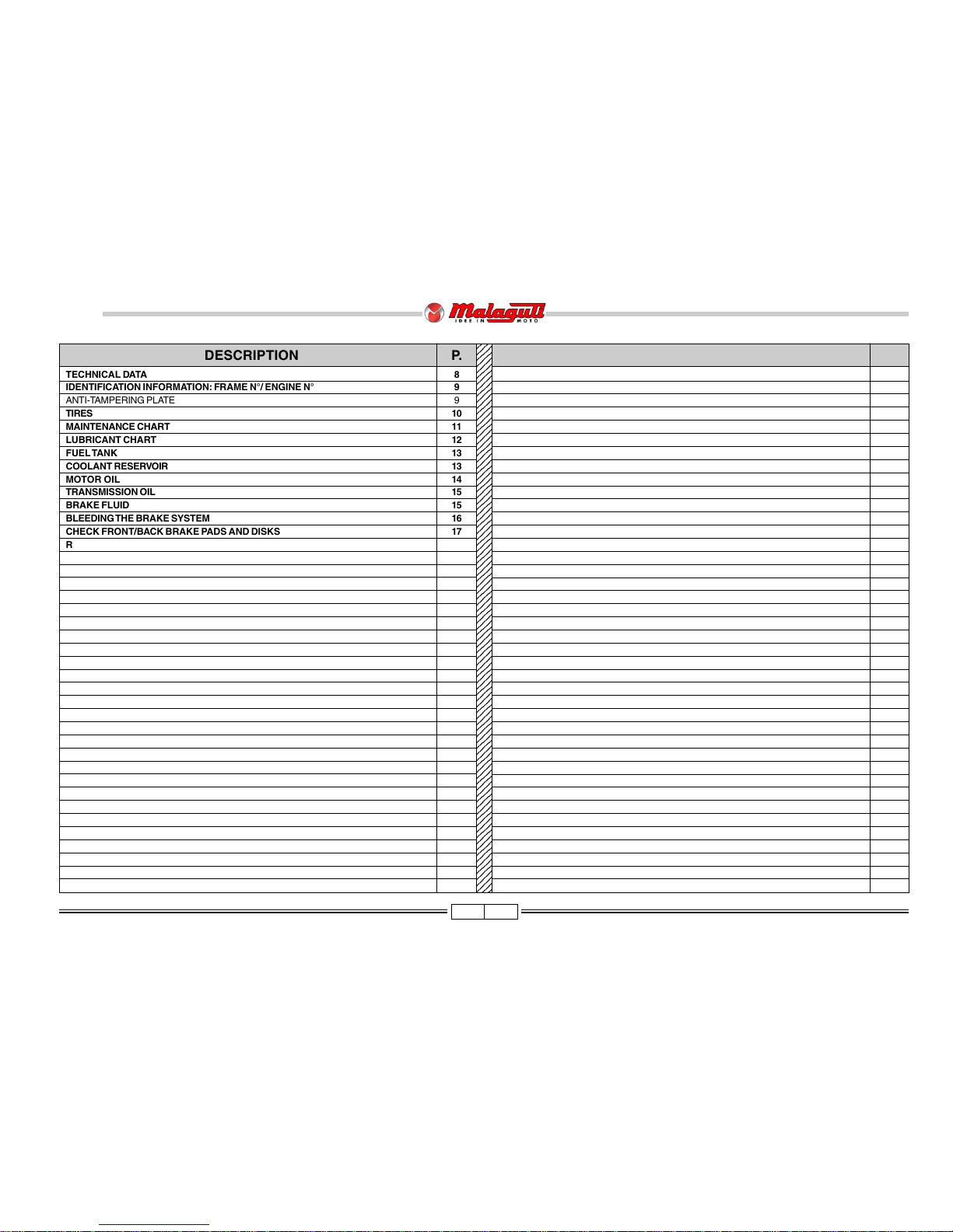
DESCRIPTION P.
TECHNICAL DATA 8
IDENTIFICATION INFORMATION: FRAME N°/ ENGINE N° 9
ANTI-TAMPERING PLATE 9
TIRES 10
MAINTENANCE CHART 11
LUBRICANT CHART 12
FUEL TANK 13
COOLANT RESERVOIR 13
MOTOR OIL 14
TRANSMISSION OIL 15
BRAKE FLUID 15
BLEEDING THE BRAKE SYSTEM 16
CHECK FRONT/BACK BRAKE PADS AND DISKS 17
REPLACE PADS 17
FORK 18
SHOCK ABSORBER ADJUSTMENTS 18
DASHBOARD - DIGITAL CLOCK 19
KEY SWITCH 20
HANDLEBAR CONTROLS - LEFT CONTROL - RIGHT CONTROL 20
ENGINE STARTER 20
LIGHTS 21
LIGHT BULB REPLACEMENT - LIGHT BEAM ADJUSTMENT 22
FUSES 23
BATTERY 24
SPARK PLUG 25
DISMANTLING AND REMOVAL PROCEDURES FOR COMPONENTS 26
REASSEMBLY NOTES 26
WINDSCREEN SUPPORTS 26
WINDSCREEN 26
REAR-VIEW MIRROR 26
UPPER HANDLEBAR COVERS 27
DASHBOARD 28
LOWER HANDLEBAR COVERS 29
UPPER SHIELD 30
FRONT SHIELD 31
ACCESS (motorbike parts - shield parts) 32
CHANGE LIGHT BULB 33
FRONT FAIRING 34
SIDE STRUTS 35
LEGSHIELD 35
Page 8
8 03/09
125 - 160 cc
BlogBlog
BlogBlog
Blog
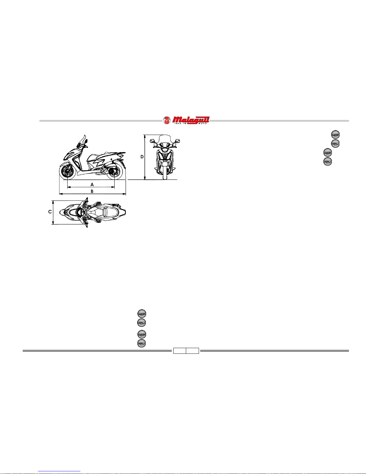
DIMENSIONS
Wheel base (A) m .......................................................................................1,470
Max. length (B) m........................................................................................ 2,090
Max. width (C) m .........................................................................................0,750
Max. height (D) m........................................................................................ 1,330
Kerb weight kg ...............................................................................................155
Max. load with rider, passenger and luggage kg ..............................................180
CAPACITY
Engine oil cm3 ........................................................................................... 1000*
Transmission oil cm3 ................................................................................... 150*
Fuel tank (total) l ................................................................................. 8,0* (3,0*)
ENGINE: 2 valve - 4 stroke single cylinder:
Type ............................................................................................. MALAGUTI 03
MALAGUTI 04
n° Cylinders ...................................................................................................... 1
Bore x stroke mm ......................................................................... Ø 52,4 x 57,8
Ø 58,0 x 57,8
Capacity cm3 .................................................................................................125
153
Compression Ratio ...................................................................................10,6 : 1
11,3 : 1
Cooling ........................................................................................................ liquid
Starting system ............................................................................ electric starter
lubrication system ................................................................................ wet sump
SPARK PLUG
Type ............................................................................................ NGK DPR7EA9
TRANSMISSION
Primary drive: automatic transmission by V-belt speed change gear
Final: by gears.
Automatic centrifugal dry clutch.
FUEL SYSTEM
Electronic fuel injection with electric fuel pump.
Fuel: unleaded petrol.
IGNITION
Digital
BRAKES
Front brake: disk type Ø 225 mm double piston hydraulic caliper Ø 25 mm
Rear brake: disk type Ø 220 mm piston hydraulic caliper Ø 34 mm
CHASSIS
High-tensile steel tubes
SUSPENSIONS
Front: hydraulically fork Ø 35 mm; Stroke: 87,5 mm.
Rear: Swinging engine with double hydraulic shock absorber. Stroke: 74 mm.
BATTERY
Type 12V, 7Ah, no maintenance.
TIRES
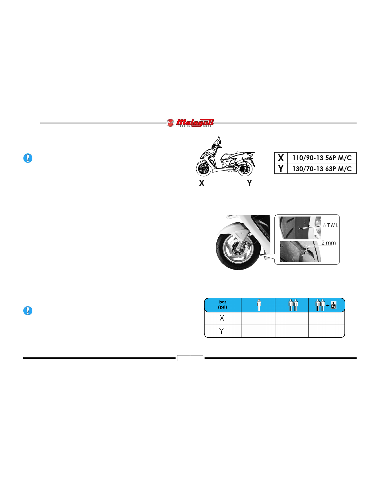
Front: 110/90 - 13 56P M/C (tubeless)
Rear: 130/70 - 13 63P M/C (tubeless)
* Indicative Value
F. 1
SPECIFICATIONS
Page 9
9 03/09
125 - 160 cc
BlogBlog
BlogBlog
Blog
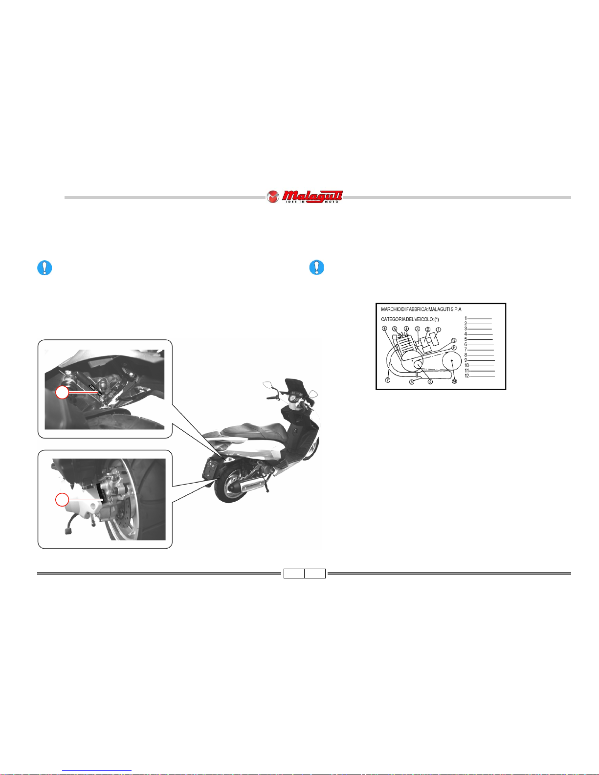
IDENTIFICATION DATA: FRAME N° / ENGINE N°
• The vehicle’s identification number (VIN) (A) is located on the rear side of the chas-
sis, under the helmet compartment.
• Engine identification data are located on the left-hand engine crankcase (B).
Any alteration to the vehicle identification data is pursued by the Law.
• When ordering spare parts, also quote the vehicle identification data.
ANTI-TAMPERING PLATE
• An anti-tampering plate, bearing all vehicle identification data required by Directive
97/24/CE. Is fitted inside the helmet compartment. If you have the helmet compartment
replaced, make sure the plate is fitted too.
Do not remove or alter this plate.
F. 4
A
B
F. 3
F. 2
Page 10
10 03/09
125 - 160 cc
BlogBlog
BlogBlog
Blog
1.9 1.9 1.9
(27.6) (27.6) (27.6)
2.0 2.1 2.1
(29.0) (30.5) (30.5)
TYRES
Type: Tubeless (without inner tube)
It is possible to use tyres with load and speed indexes that are higher than
or identical to those indicated.
It is however necessary for speed indexes to be identical for both tyres.
USE ONLY TYRES WITH THE RELEVANT TYPE APPROVAL.
• There are T.W.I. marks all around the tyre sides. These correspond to tyre wear
indicators situated in the tyre’s tread; if there is no difference between the thickness
of the tyre wear indicators and the tread depth, the tyre must be replaced.
F. 6
F. 5
Minimum tread depth (front and rear) is 2 mm (F. 6).
Tyre inflation pressure must be adjusted while the tyre is at ambient
temperature.
Pressure differing from that indicated can lead to higher fuel
consumption, irregular wear of the tire, impaired vehicle performance
and riding conditions.
PRESSURE
Page 11
11 03/09
125 - 160 cc
BlogBlog
BlogBlog
Blog
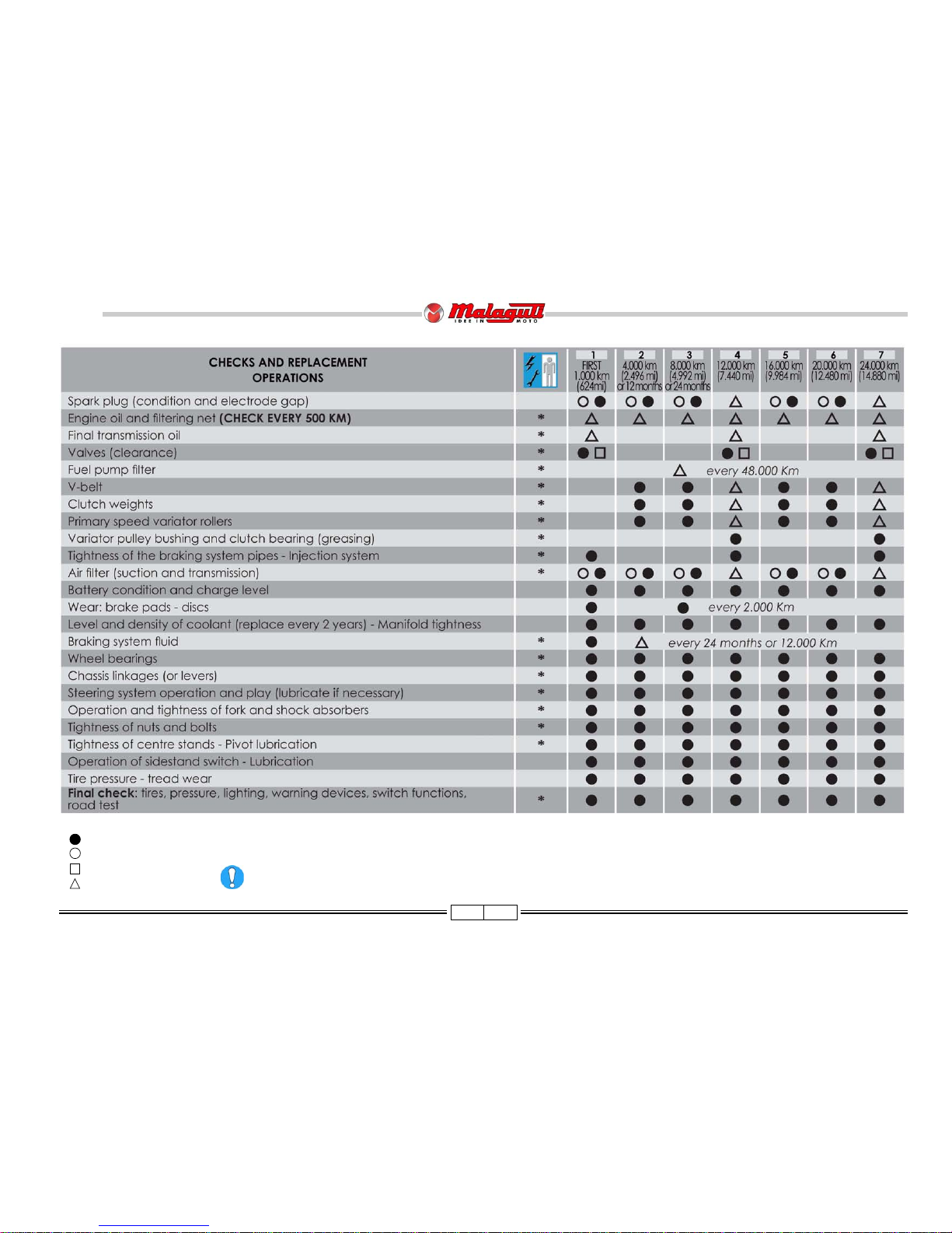
NOTE - Maintenance operations should be performed more frequently if the vehicle is used in rainy weather, in dusty places or on rough
terrain.
Due to their simplicity, checks with no asterisk CAN also be carried out by technicians not authorised by MALAGUTI, but under
their direct responsibility.
Nr. : coupon
: check
: clean
: adjust
: replace
MAINTENANCE TABLE
Page 12
12 03/09
125 - 160 cc
BlogBlog
BlogBlog
Blog
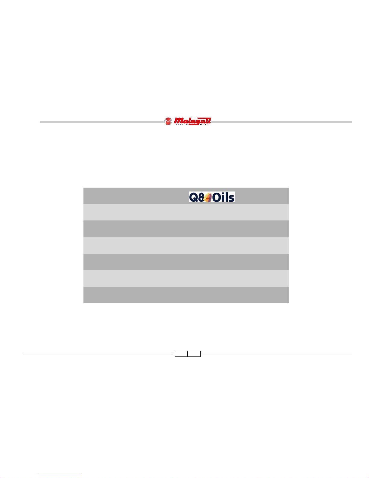
LUBRICANT TABLE
NOTE - Use only recommended products.
LUBRICANTS
ENGINE OIL (4 STROKE) CLASS 10W 40
ENGINE TRANSMISSION OIL CLASS 10W 40
AIR FILTER LUBRICANT AIR FILTER OIL
RADIATOR FLUID TOP FLUID
BRAKE CIRCUIT FLUID BRAKE FLUID DOT 4
FORK ROD OIL FORK OIL
Page 13
13 03/09
125 - 160 cc
BlogBlog
BlogBlog
Blog
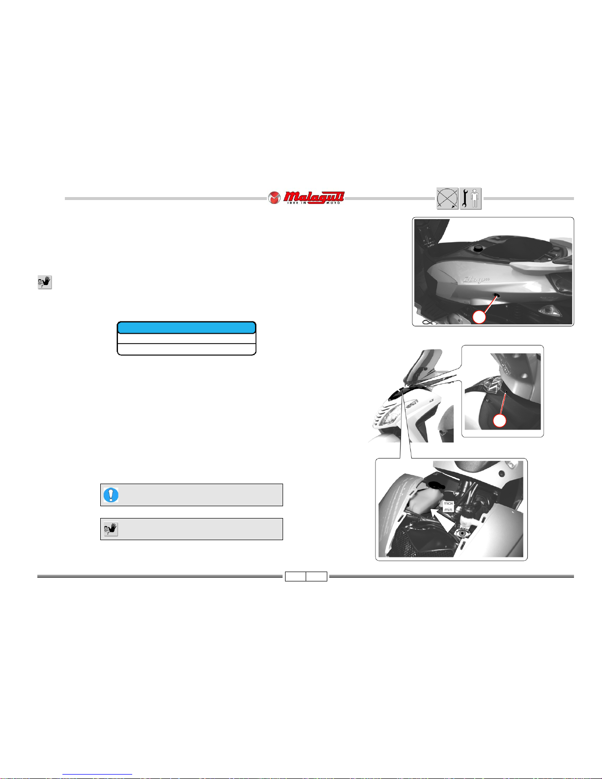
FUEL TANK Liters
TOTAL TANK CAPACITY 8,0
RESERVE 3,0
FUEL TANK
• Inser t the ignition key in the switch block and it into the lock on the left hand side of the seat (B).
• Open seat by turning ignition key clockwise.
• The quantity of fuel, as well as a low fuel level, are displayed by the corresponding indicator on the right hand side of
the instrument board.
Petrol is extremely inflammable; avoid approaching the fuel filler - also during filling - with lit cigarettes or
naked flames (for instance matches). Danger of fire!
COOLANT TANK
• To gain access to the tank containing the coolant, loosen the two screws (A) next to the handlebar
and remove the front fairing.
• Check the level of coolant with respect to the “MIN” and “MAX” notches, next to the tank, by
checking through the sight glass located under front fairing on the right hand side.
F. 7
B
If it needs to be topped up, use the product
specified in the lubricants chart.
Do not remove the cap when the engine is hot.
F. 8
Use UNLEADED PETROL.
A
Page 14
14 03/09
125 - 160 cc
BlogBlog
BlogBlog
Blog
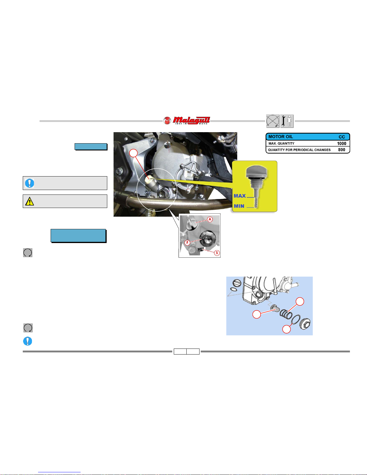
F. 1 0
F. 9
A
1
3
2
Check the level with the plug
tightened.
every 2,000 km
CHECK LEVEL
• The engine must be cold and the vehicle
on level ground.
• The level is shown on the cap/ dipstick
(A).
Top with the oil specified in the
lubricant chart.
ENGINE OIL
• Place an appropriate drain pan under the engine (with the vehicle on flat
ground).
• Pull out the cap/ dipstick (A).
• Unscrew the drain plug (S) and let all the used oil drain out.
• Remove the filter/plug (F).
• Wash the screen (1) with solvent or if it is damaged, replace it.
• Check the wear conditions of the O-Ring (3) and replace if necessary.
• Reassembly: O-Ring (3)- Spring (2)- Screen (1) and tighten the filter/plug.
• Screw on and tighten the drain plug (S).
• Top up the engine with 800 cc of Q8 CLASS 10W40 oil and replace the cap/
dipstick.
Start the engine; leave it running for a few minutes, and check that there
are no leaks.
Dispose of used oil in accordance with current laws in force.
CHANGE
Warm up the engine for a few minutes and then shut it off.
• After the first 1,000 Km
• Every 4,000 KM
Page 15

15 03/09
125 - 160 cc
BlogBlog
BlogBlog
Blog
F. 1 1
S S
F. 1 2
B
A
CHECK LEVEL/ TOP UP
• Cold engine
• Vehicle on level ground.
• Place a drip pan under the engine.
• Unscrew the oil filler screw (A).
• If necessary, top up with oil specified in the lubricant
chart until the oil starts to overflow.
• Screw on the screw (A).
TRANSMISSION OIL
CHANGE
If there is any debris or water in the brake fluid, it is essential that it be completely changed and the brake system must be bled. Excessive elasticity in the
brake lever is usually an indication that air is in the system.
CHANGE
• After the first 1,000 Km
• Every 12,000 Km
• Cold engine
• Vehicle on level ground
• Place a drip pan under the engine.
• Unscrew the oil filler screw (A).
• Unscrew the drain screw (B)
• Drain out all the used oil.
• Clean the threads of the drain screw and screw back on.
• Refill the crankcase with oil specified in the lubricant
chart until the oil starts to overflow.
• Screw back on the screw (A).
CHECK
• Visually check by way of the warning signal (S) located on the front and back
brake reservoir, with the vehicle on level ground and perfectly straight.
• The fluid level must be 3mm from the lower limit of the warning signal.
BRAKE FLUID
every 30 days
Every 12,000 Km or 24 months
Do not mix different oil types when topping off.
Page 16
16 03/09
125 - 160 cc
BlogBlog
BlogBlog
Blog
F. 1 3
F. 1 4
F. 1 6
V
12 ± 16%
B
D
V2A
C
V
C
V
F. 1 5
A
V2
B
S
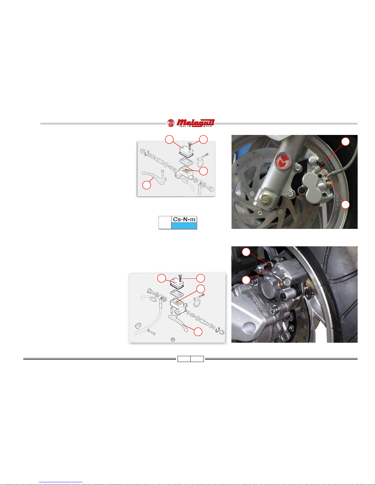
BLEED BRAKE SYSTEM
FRONT CALIPER
NOTE - Position the vehicle in a stabile manner and
perfectly on level ground.
• Remove the (right side) oil pump reservoir cover
(A), unscrewing the relative screws (V"), in order to
be able to top off the fluid.
• Fill the right brake fluid reservoir (B) to the highest
level.
• Remove the rubber hood (C) of the bleeder screw
(V) and insert a rubber tube to recover the brake
fluid.
• Pump the right brake lever (D), prime it and bring
the system in pressure.
• Keeping the brake lever pumped, loosen the bleeder screws (V), to allow air to escape. Then, tighten
the bleeder screw (V).
REAR CALIPER
• To bleed the rear caliper, follow the same operation
above, but pump the left brake lever (S).
• Repeat the operation, until only liquid comes out of
the rubber tube.
• Top up the brake fluid level in the reservoir (B).
Page 17
17 03/09
125 - 160 cc
BlogBlog
BlogBlog
Blog
F. 2 0 F. 2 1
F. 1 7
F. 1 8
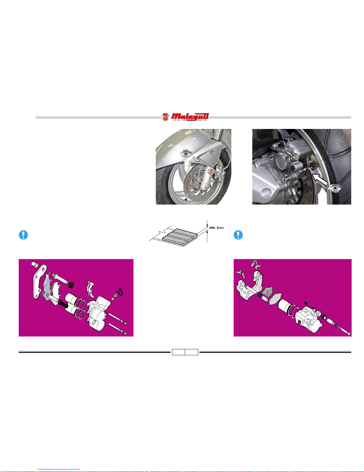
CHECK FRONT/BACK BRAKE PADS AND DISKS
• Check the condition of front and back brake pads and discs
every 2,000 Km.
• Carry out a visual check on the thickness of the brake pads as
shown in the illustration.The minimum thickness of the brake
pad friction material must not be less than 2mm.
• Replace the pads if they are close to the allowed limit, or if they
are damaged.
REPLACING PADS
REAR BRAKE
FRONT BRAKE
The procedures for replacing front and back brake pads
can be deduced from the illustration shown below.
(M/N table bill of materials).
F. 1 9
To remove back brake pads, see Rear brake caliper
removal (page 61).
Page 18
18 03/09
125 - 160 cc
BlogBlog
BlogBlog
Blog
Adjust both shock absorbers using these instructions.
Uneven adjustment can compromise the stability of the vehicle.
Perform adjustments using the special key equipped on the ring nut (A), located on the upper part of the shock absorbers; turning
it anti- clockwise will increase the strength of the spring (increase in load)
SHOCK ABSORBER ADJUSTMENTS
5 adjustment positions are included:
1) driver only (to 75 kg)
2) driver only (over 75 kg)
3) driver and case
4) driver and passenger
5) driver, passenger, and case.
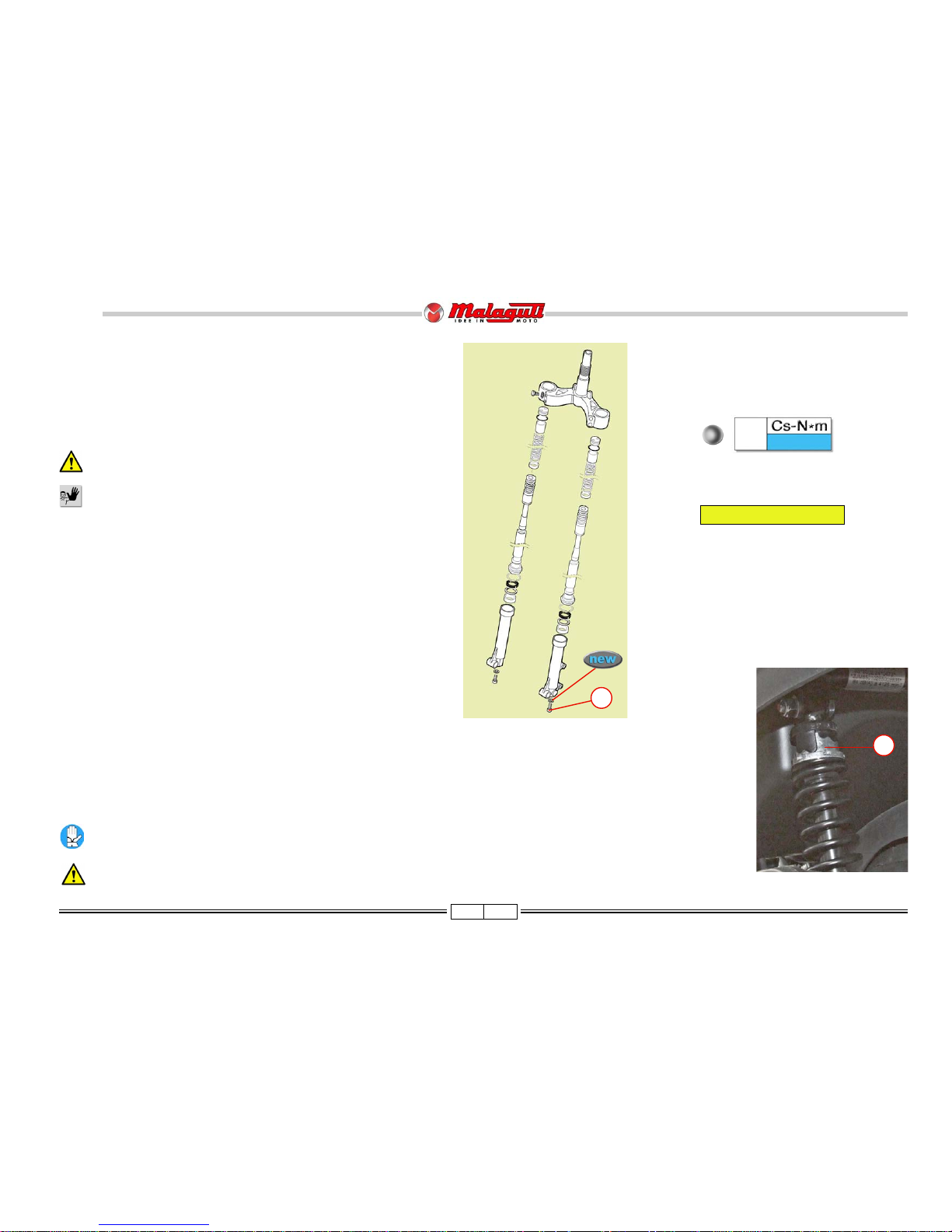
CHANGE FORK OIL
• Place an appropriate drip pan under the slider and remove the screws (V).
• Drain out as much oil as possible.
• Proceed to dismantle the fork legs, as described p. 57.
• Turn the fork legs upside-down, to let the remaining oil drain out.
Hydraulic oil is corrosive and may cause personal injury.
Do not improperly dispose of used oil in the environment.
• Reassemble the fork components and the fork on the
motorcycle.
• Carefully pour the "new" oil in the fork.
V
17 ± 15%
FORK
F. 2 3
A
F. 2 2
V
• Remount the drain screw (V).
NOTE - When remounting, replace the copper washer
located under the screw (V).
Quantity per fork: 98 cc.
Page 19
19 03/09
125 - 160 cc
BlogBlog
BlogBlog
Blog
F. 2 4
9
8
7
6
2
1
3
4
5
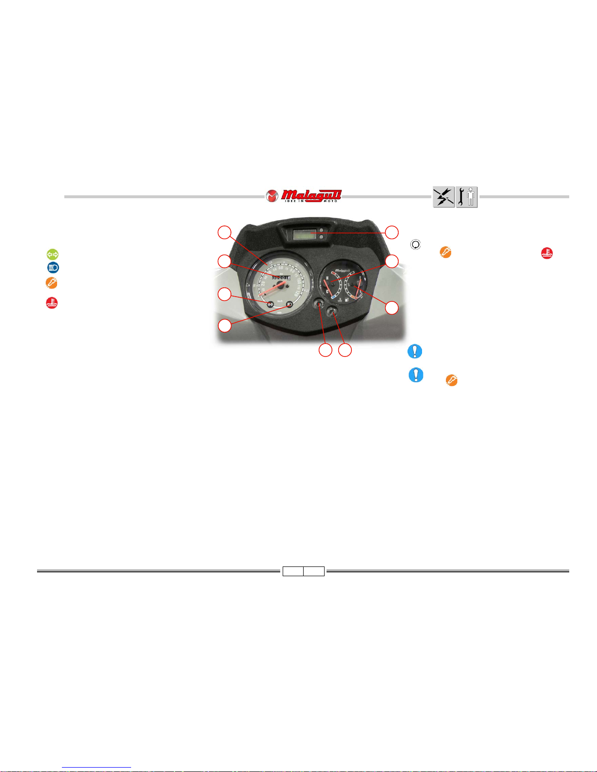
ELECTRIC/SERVICE MALFUNCTION WARNING
LIGHT
When the starter key is turned in the switch in the
position, without starting the engine, the warning light (as well as the warning light ) will
remain on for a few seconds to verify the functioning,
and it will normally shut off after this.
If it stays on longer (fully and/or flickering) it means:
• Electrical Malfunction (blinking light): indicates a
malfunction in the electrical system.
• SERVICE (15 short blinking lights): indicates the
need to perform programmed maintenance (see the
Maintenance Chart on page 11).
In both cases, reset the signal after performing
the necessary operations.
The warning light interval of the SERVICE
sign of the may have different meanings as shown in the Maintenance Chart, depending on the vehicles conditions of use.
DIGITAL CLOCK
• Date and month readout
Press the top button once (after a few seconds the clock will automatically reappear).
• Seconds readout
Press the top button twice; to restore the initial configuration, press the button again.
To set the clock and calendar, use the two buttons on the right hand side of the dial, starting with the time display.
• Setting the month
Press the lower button twice; and then with the top button select the exact number.
• Setting the date
Press the lower button three times; and then using the top button select the exact number.
• Setting the time
Press the lower button four times, and then using the top button select the exact number.
• Setting the minutes
Press the lower button four times, and then using the top button select the exact number.
Press the lower button once again to return to the time display. Confirm modifications by pressing the top button.
DASHBOARD
1) Speedometer
2) Odometer
3) Turn signal warning light (green)
4) High beams warning light (blue)
5) Electric/SERVICE Malfunction warning
light (orange)
6) coolant temperature too high warning light
(red)
7) Fuel gauge indicator
8) Coolant temperature indicator (red zone:
temperature too high)
9) Digital clock
Page 20
20 03/09
125 - 160 cc
BlogBlog
BlogBlog
Blog
F. 2 5
B
A
1
2
3
4
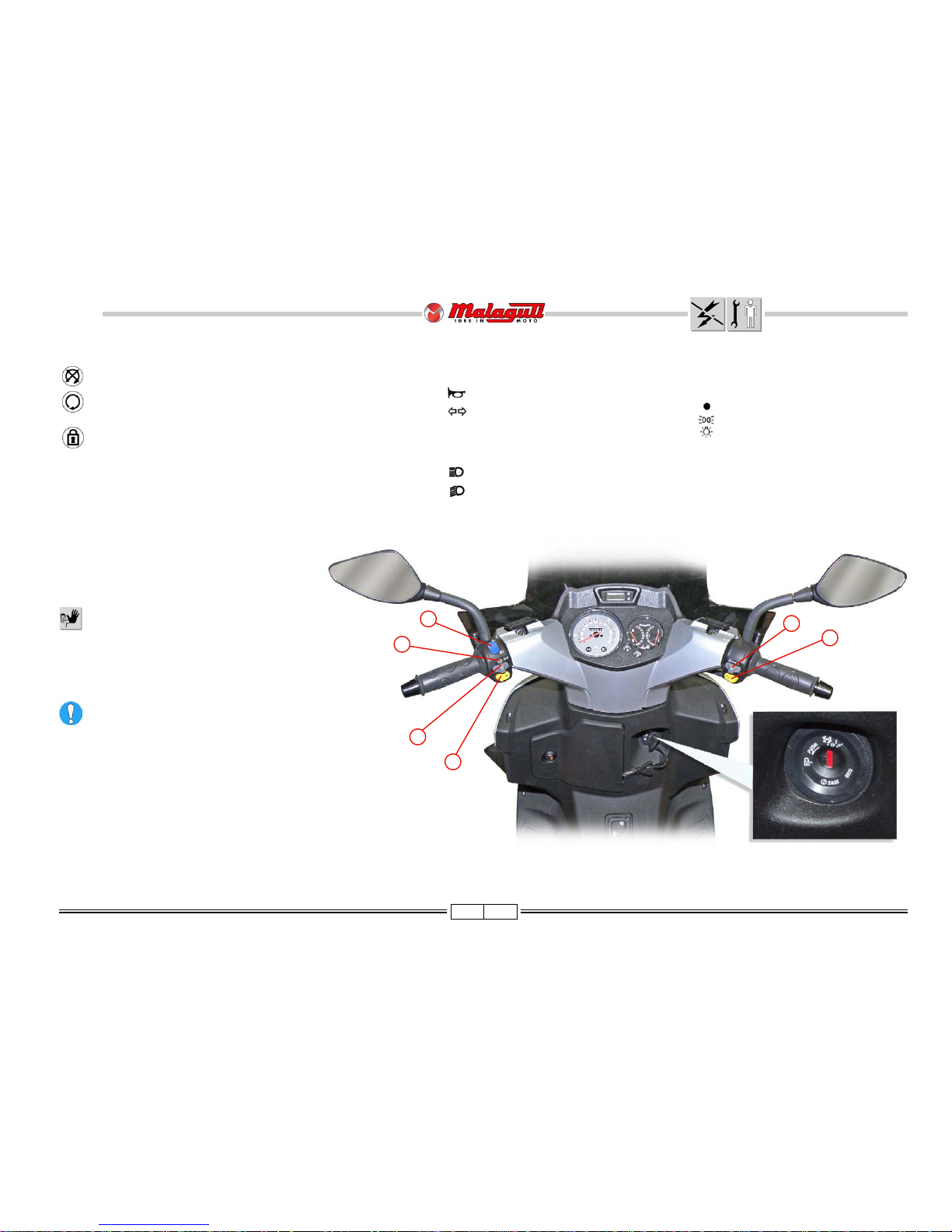
KEY SWITCH
Ignition inhibited (extractable key)
Preset starting position (non extractable key)
Steering lock insert (Ignition inhibited: extractable key).
In case both of the equipped keys are lost the entire
locking kit must be replaced.
STARTING THE ENGINE
Before pushing the starter button to start the motor,
first pull the front or rear brake lever and keep it
pulled.
Do not start the engine in a closed ambient,
because the exhaust is highly toxic.
To not damage the injection system, never
operate the "START" button if the fuel tank
is empty, or turn the key switch to "ON".
If the engine does not start, release the starter switch, wait a moment, and then press it
again. In order not to drain the battery, do not
operate the starter for more than 10 seconds
on each try. Do not rev the engine to its limit
when it is cold.
Start the engine with the headlights off.
HANDLEBAR CONTROLS
RIGHT CONTROLS
A) light switch:
right= off
center= tail and dashboard lights
left= high/low beams
B) Electric starter button
LEFT CONTROLS
1) Horn button
2) Turn signals switch.
3) Turn signals shutoff switch
4) Turn on lights:
high beam
low beam
Page 21
21 03/09
125 - 160 cc
BlogBlog
BlogBlog
Blog
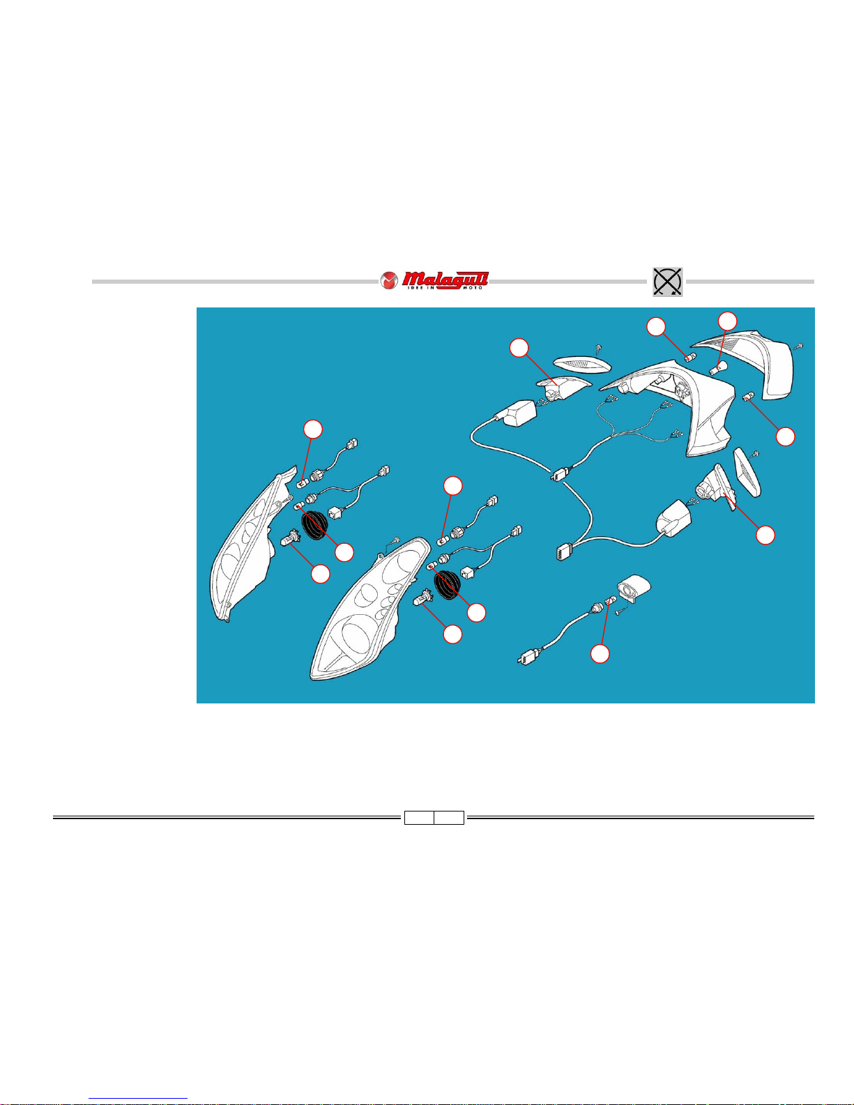
LIGHTS (12 V)
HEADLIGHT
(Quartz halogen lamps)
A) High/Low beam lights:
55W (H7).
B) Tail lights:
5W (W7y5).
TURN SIGNALS
FRONT
C) Bulbs: 10W (RY10W).
TAIL LIGHTS
D) Tail lights:
5W (R5W).
E) Stop lights:
21/25W (P21/5W).
TURN SIGNALS
REAR
F) 10W (W10W).
NUMBER PLATE LIGHT
G) 5W (W5W).
A
E
B
F
C
G
D
C
A
B
F
D
F. 2 6
Page 22
22 03/09
125 - 160 cc
BlogBlog
BlogBlog
Blog
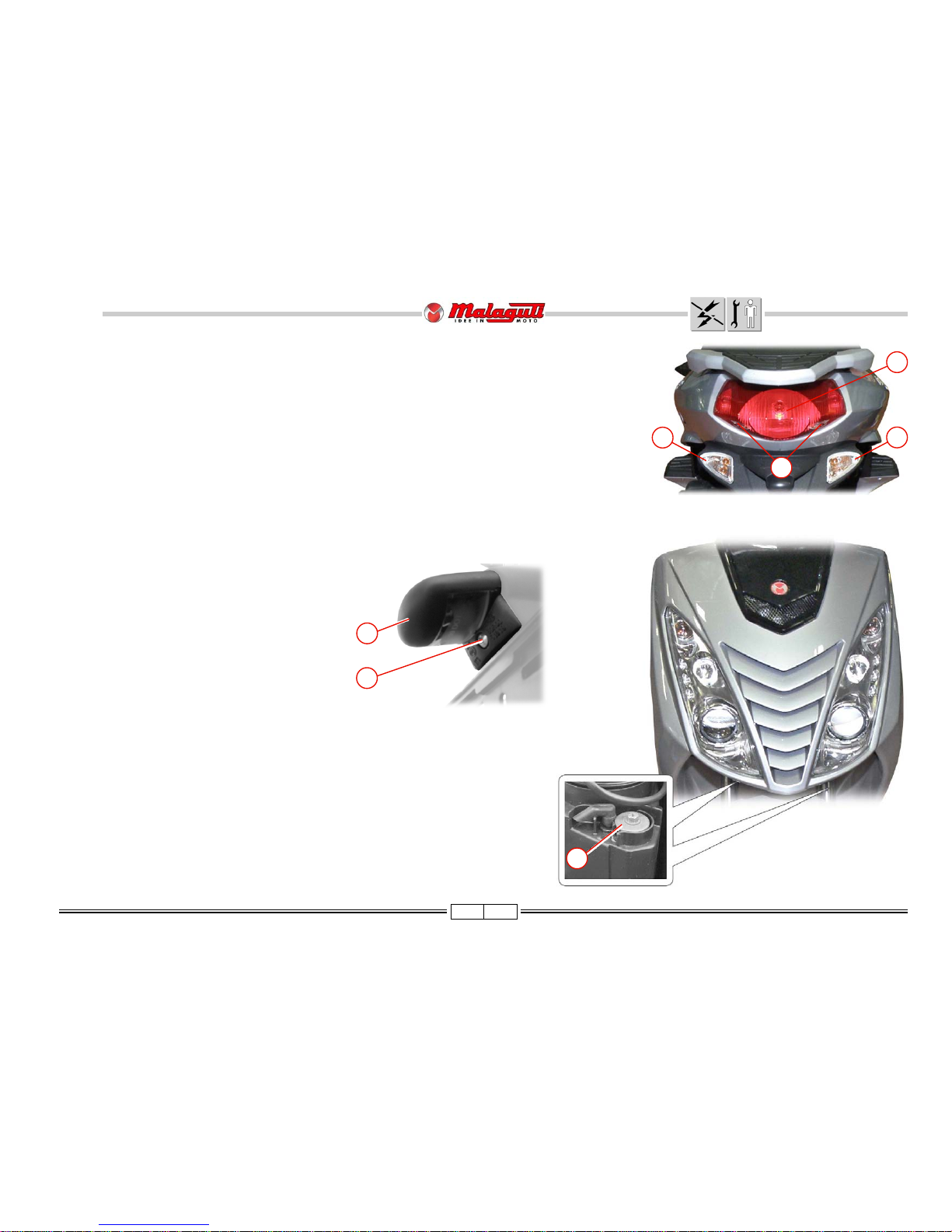
LIGHT BULB REPLACEMENT
HEADLIGHT
• In order to access the headlight bulbs, refer to the topics at page (33).
TURN SIGNALS
FRONT: See page (33).
REAR: Undo the screws (V) and remove the rear reflectors. Turn the bulb anti-clockwise and replace it by a new
identical one.
TAIL LIGHTS
• Undo the screws (V”) and remove he tail light cover. This operation will allow releasing the whole light unit (body +
cover).
LIGHT BEAM ADJUSTMENTS
To check/adjust the beam, proceed as follows:
• Put the vehicle in running conditions at 10 metres from a wall.
• Turn the low beams on and keep the vehicle vertical, without stand or driver.
• Using an adjustable spanner, turn the projector screw (R), bearing in mind that turning anti-
clockwise raises the beam and vice versa.
F. 2 7
V
V
V2
F
F. 2 8
F
W
NUMBER PLATE LIGHT
• Undo the screw (W) and remove the tail light cover (F).
• Remove the rubber bulb holder from the plastic cover and
replace the bulb.
NOTE - Before reassembling any component removed to
replace one or more bulbs, check the light operation.
F. 2 9
R
Page 23
23 03/09
125 - 160 cc
BlogBlog
BlogBlog
Blog
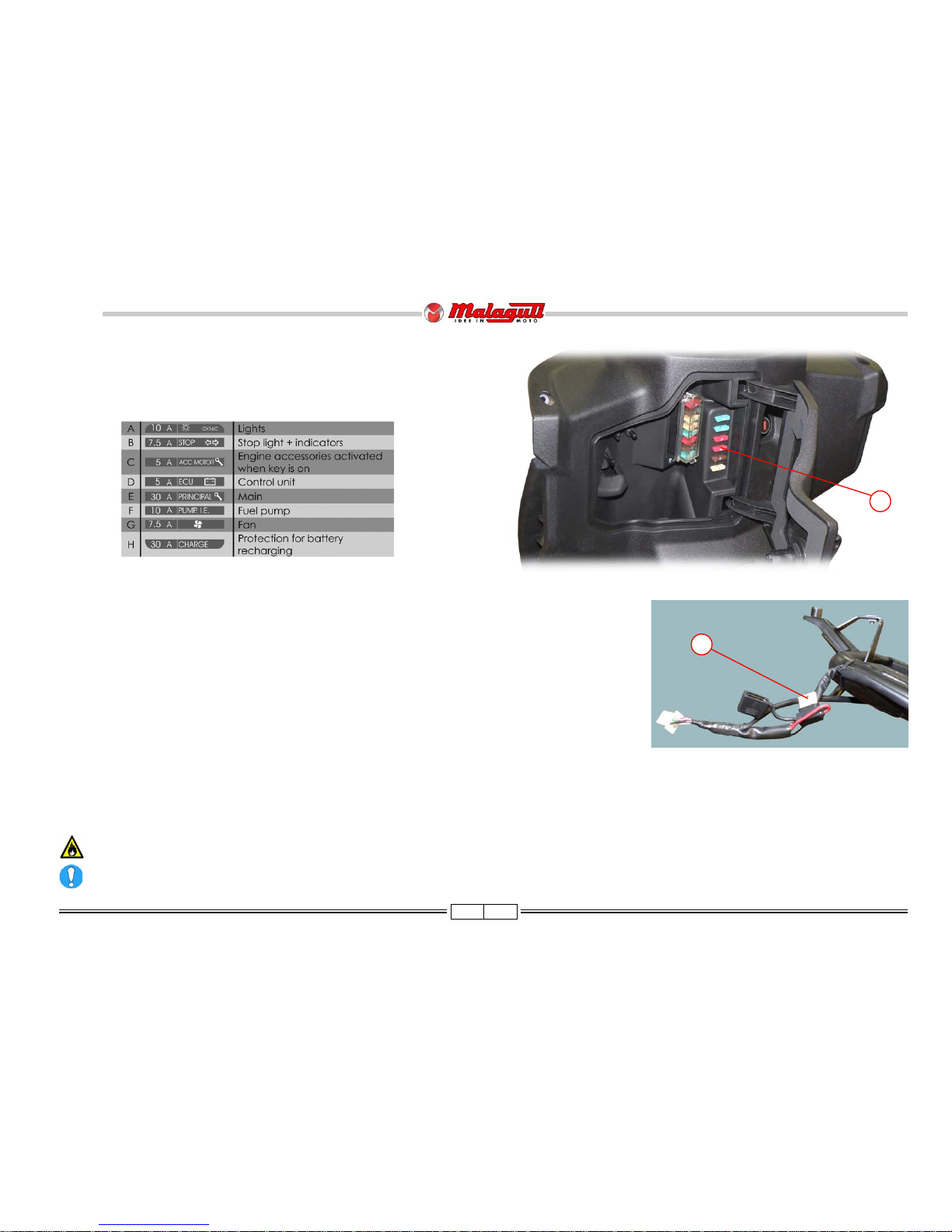
REPLACING THE FUSES
• Extract the blown fuse and replace it with one of the same capacity. Inside the compartment, you will find some spare fuses (S).
• Check that the fuse you are using has the same amperage of the fuse you are replacing.
F. 3 0
FUSES
The electrical wiring includes 9 fuses, protecting the main components against faults.
8 are located in the glove compartment.
Do not replace fuses with others that have a higher capacity, as it could seriously damage the electrical system and cause the vehicle to catch fire if there is a
short circuit.
It is important to identify the cause of blown fuses.
S
• A 5A fuse (I) below the helmet compartment is installed to protect the recharge plug.
F. 30/a
I
Page 24
24 03/09
125 - 160 cc
BlogBlog
BlogBlog
Blog
F. 3 2
F. 3 3
F. 3 4
P
A
F. 3 1
W
S
V3
B
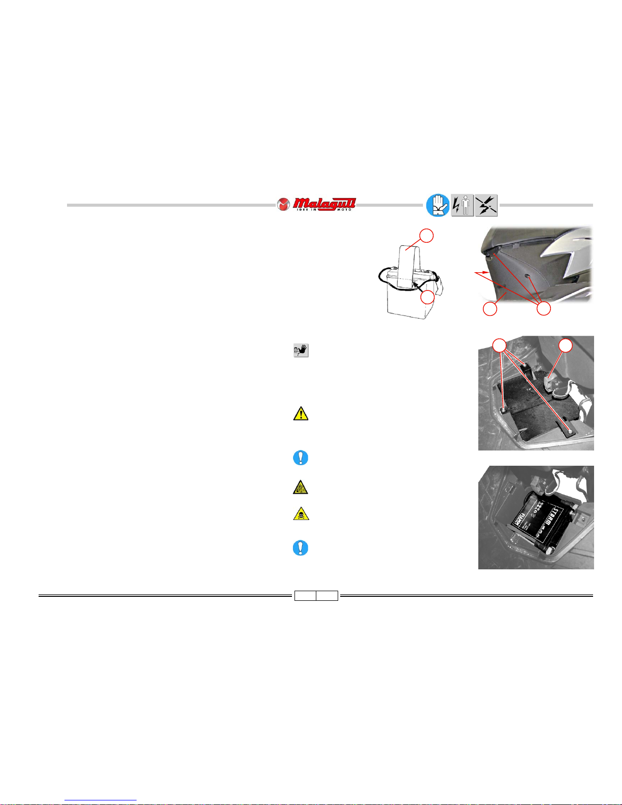
• Replace the previously removed 30 A general protection fuse
in its place.
• Check that the battery and cables are properly positioned;
then remount the battery fastening cover.
• Remount the central panel under the seat.
NEVER invert the cable connections.
Do not use the battery without the battery
inserted and connected to wires of the main
harness. This could cause breakdowns and
short circuits in the electrical system and
components.
It is advisable to use gloves and protective
eyewear, when the battery must be removed
from its housing; for example, when it needs to
be recharged.
Make sure that the tilt sensor (B) is perfectly
horizontal.
Danger of explosion! Do not use open flames
(lighters, matchsticks, etc.).
The battery contains highly toxic sulphuric acid.
Avoid contact with the eyes, skin, and clothes.
Keep the battery out of reach from children.
If for charging/maintenance of the battery the
special electrical outlet connection is used,
open the battery case to permit proper
ventilation.
CHARGE BATTERY
• To carry out this operation, it is advisable to remove the
battery from its housing, unless the special electrical outlet is
used.
• Disconnect cables.
• It is a good rule to recharge using amperage that is equal to
1/10 of the power of the battery.
• Remount the battery, paying attention to connect the positive
cable (red/blue) to the + pole and the negative cable to the pole.
• Properly tighten the battery clamps.
• It is important that the battery always remains fully charged;
therefore, during the winter months or when the vehicle remains unused, it should be recharged at least once a month.
BATTERY (12V - 9Ah)
The battery housing is located in the central tunnel.
BATTERY ASSEMBLY (PRE-DELIVERY OPERATION)
• Take the battery that has been previously charged
• Apply the adhesive strip (A) supplied in the kit, by removing
the protective film located on the end of the adhesive area,
shown by the arrows (P).
• Remove the 30 A general protection fuse.
• Unscrew the three screws (V3) and remove the central panel
under the seat (S).
• Remove the battery fastening cover by removing the 3
screws (W).
• Inser t the battery, ensuring it fits in its housing.
• Connect the battery to the cables
- positive pole (+) RED/BLUE wires
- negative pole (-) BLACK wires
• Properly tighten the battery clamps.
• Properly position the battery clamps.
Page 25

25 03/09
125 - 160 cc
BlogBlog
BlogBlog
Blog
F. 3 6
F. 3 5
C
P
V3
Spark plugs with a thermal grade that is different than that deduced by the advised
symbols may seriously damage the engine.
Replace all spark plug with cracks on the insulator or corroded electrodes.
SPARK PLUG
REPLACEMENT
Remove the spark plug when the engine is cold.
Type of spark plug to be used: NGK DPR7EA9
• For maintenance, disassemble the central panel under the seat (P), remove the
fastening screws (V3) and lift the internal profile (with the help of a screwdriver)
that is held on two lugs in the foot rest board, carefully extract the hood (C ),
with small clockwise and anti clockwise movements; then unscrew the spark
plug.
• Examine the condition of the sparkplug. Deposits and colorations of the insulator provide useful information on the thermal grade, on the carburetion, on the
lubrication and on the general condition of the engine. If there is a light brownish
color on the insulator around the central electrodes, it means that it functions properly.
• After removing the sparkplug, proceed to clean thoroughly the electrodes and insulators, using a
metallic brush. Adjust the electrode gap, using a laminar feeler gauge: the gap must be 0,6 ÷ 0,7 mm
• Remove any residue, using jets of compressed air.
• Grease the sparkplug threads with motor oil and manually rescrew it.
• Tightening the spark plugs:
every 12,000 km
17,5
Page 26

26 03/09
125 - 160 cc
BlogBlog
BlogBlog
Blog
PROCEDURES FOR DISMANTLING AND
REMOVING COMPONENTS
REASSEMBLY NOTE
WINDSCREEN
SUPPORTS
• V2.
• Supports (A).
F. 3 7
F. 3 8
V2
A
A
F. 3 9
D
REAR VIEW MIRRORS
RIGHT SIDE MIRROR
• Uncover and loosen the nut (D).
• Unscrew the window holder arm, by turning it clockwise.
LEFT SIDE MIRROR
• After undoing the nut (D), unscrew the mirror holder, anti-clockwise.
V4
WINDSCREEN
• V4.
• Windscreen.
Page 27

27 03/09
125 - 160 cc
BlogBlog
BlogBlog
Blog
• W2.
• V2.
• Release the upper
handlebar cover,
paying attention not
to damage the
anchoring teeth (A).
• Undo the odometer
cable ring nut from
the instrument panel
coupling.
F. 4 0
F. 4 1
F. 4 2
V2
W2
A
UPPER
HANDLEBAR
COVERS
• Disconnect the
connectors (C - D).
F. 4 3
C
D
Page 28

28 03/09
125 - 160 cc
BlogBlog
BlogBlog
Blog
• V2.
F. 4 4
F. 4 7F. 4 6
DASHBOARD
• V4.
• V2/a.
V4
V4
V2
V2a
• Disconnect the
connector (A).
F. 4 5
A
Page 29

29 03/09
125 - 160 cc
BlogBlog
BlogBlog
Blog
ACCESS
(after removing the upper handlebar cover)
1) Front brake pump
2) Hydraulic front brake union
3) Front brake "stop" switch
4) Rear brake "stop" switch
5) Rear brake pump
6) Hydraulic rear brake pump union
7) Right switch connector
8) Left switch connector
LOWER HANDLEBAR COVER
• V2.
•V.
• Release the gas transmission (G).
• Remove the lower handlebar cover (C) pushing it backwards.
V
3 ± 10%
F. 4 8
1
3
2
6
5
4
7
F. 4 9
8
7
V2
V
V2
G
C
Page 30

30 03/09
125 - 160 cc
BlogBlog
BlogBlog
Blog
UPPER
SHIELD
• V2.
• Tapping slightly with
the hand palm,
release the upper
cover.
When reassembling, make sure
the shield lower teeth are properly
engaged into the slots.
ACCESS
1) Steering adjusting nut.
2) Radiator cap
3) Connector electric fan
4) Connector diagnosis socket
5) Front headlight connector
6) Expansion reservoir plug
7) Handlebar screw
V2
F. 5 0
F. 5 1
V
1 ± 10%
F. 5 2
6
5
A
4
1
2
3
7
Page 31

31 03/09
125 - 160 cc
BlogBlog
BlogBlog
Blog
FRONT
SHIELD
• V2.
V2
1 ± 10%
W
1 ± 10%
•W.
A
V2
F. 5 3 F. 5 4
F. 5 5
W
• Unplug the
connector (B) and
remove the front
shield completely.
F. 5 6
B
• Remove the shield with
moderation, being careful
to not damage the
hooking elements (A).
Page 32

32 03/09
125 - 160 cc
BlogBlog
BlogBlog
Blog
F. 5 8
(shield parts)
1) Turn signals
2) Tail lights
3) High/Low beam lights
F. 5 7
2
1
2
1
3
2
1
ACCESS
(motorbike parts)
1) Radiator
2) Electric fan
3) Fork stem screw
3
Page 33

33 03/09
125 - 160 cc
BlogBlog
BlogBlog
Blog
CHANGE LIGHT BULB
TURN SIGNALS
• Turn the bulb holder (A) anti-clockwise and remove the bulb (B).
TAIL LIGHTS
• Extract the bulb holder (C) and remove the bulb (D).
HIGH/LOW BEAM LIGHTS
• Release the bulb holder from the clips (E).
• Replace the bulb, paying attention not to touch the bulb glass with bare fingers.
NOTE - We recommend to test the new bulbs before reassembling the removed
components.
F. 5 9
B
A
D
C
E
Page 34

34 03/09
125 - 160 cc
BlogBlog
BlogBlog
Blog
• V4.
• W2.
• Remove the front wheel
and mud guard.
FRONT
FAIRING
• Remove the front fairing with
care.
•V.
• V1.
• V3.
• V2.
ACCESS
1) Electronic
control unit
2) Horn
F. 6 1
F. 6 2 F. 6 3
F. 6 0
V
V1
W2
V4 V4
2
1
V2
V3
V4
2 ± 10%
V2
2 ± 10%
V
V3
1 ± 10%
V1
3 ± 10%
W2
3 ± 10%
Page 35

35 03/09
125 - 160 cc
BlogBlog
BlogBlog
Blog
SIDE
STRUTS
• V4.
• V3.
•V.
LEGSHIELD
(After removing the front shield)
• V2/b.
F. 67 F. 67/a
V2
B
A
V2b
V3
V
1 ± 10%
V4
1 ± 10%
V2
5 ± 10%
• V2.
• Bag hook (A)
• Key swith lid (B).
• V2/a.
V2a
F. 6 6
F. 6 5
V
V3
F. 6 4
V4
Page 36

36 03/09
125 - 160 cc
BlogBlog
BlogBlog
Blog
SEAT
• V4.
•V. • Release the leg-fender
with care, paying
attention not to damage
the sides (A).
V4
3 ± 20%
V
1 ± 10%
CENTRAL
SECTION
UNDER THE
SEAT
• V3.
F. 6 8 F. 6 9
F. 7 0
V
V4
A
F. 7 1
V3
Page 37

37 03/09
125 - 160 cc
BlogBlog
BlogBlog
Blog
ACCESS
• Rollover sensor (A).
When reassembling the removed components, make sure that the tilt sensor is
horizontal.
An inclination of approximately 45° would prevent the engine from starting.
• V3.
• Battery cover (C).
• Battery compartment (B).
F. 7 3
F. 7 2
V3
B
A
C
Page 38

38 03/09
125 - 160 cc
BlogBlog
BlogBlog
Blog
• V3.
• Cap (T).
V3
5 ± 20%
F. 7 6 F. 7 7
T
V3
V2
F. 7 5
A
V4
F. 7 4
• After undoing
the screws
(V2), open up
the fairing, as
shown in the
figure.
• V4.
• V1.
HELMET CASE
V2
V1
P
• V2.
• Remove the seat
fastening plate (P).
• Remove the cover (A).
V2
5 ± 20%
Page 39

39 03/09
125 - 160 cc
BlogBlog
BlogBlog
Blog
• V2. • Lift the helmet
compartment.
• Remove the seat
lock unit (A).
• Disconnect the
connector (B).
• Remove the
helmet
compartment.
• In case you need
to release the
cable (C) follow
the instructions
below:
F. 8 0
V2
3 ± 20%
F. 7 8 F. 7 9
V2
A
B
C
• Move the clip (D)
sideways to
release the cable
(C).
F. 8 1
D
D
C
Page 40

40 03/09
125 - 160 cc
BlogBlog
BlogBlog
Blog
ACCESS
(after removing the helmet compartment)
A) Fuel level gauge
B) Fuel Pump
C) Pump connector
D) Fuel tank
1) Injector connector
2) Temperature gauge (coolant)
3) Throttle body
4) Coolant drainage hose
5) T.P.S. connector
6) Thermal expansion valve
4
3
2
1
B
C
A
F. 8 2
5
D
6
Page 41

41 03/09
125 - 160 cc
BlogBlog
BlogBlog
Blog
F. 8 3
F. 8 5
H
P
I
FUEL LEVEL
SENSOR
Do not smoke or use open flames,
during operations on the fuel tank.
• During operations, screw the tank cap
(A), to avoid that any foreign matter
falls inside.
• Remove the sheaths (B) and disconnect
the connector located below.
• V4.
• Remove the sensor (D).
V4
2 ± 10%
F. 8 4
D
E
F
FUEL PUMP
• Disconnect the connector (G).
• Disconnect the gas hose (H), pressing on the fitting
with one finger (R). Keep a rag close by to swab up any
leaking fuel.
• Unscrew the ring nut (I).
• Take out the pump (P).
V4
V4
When reassembling, insert the
floater (E) so that the base (D)
remains as it was originally. It is
advisable to mark the correct
position before removal. Check the
condition of the gaskets (F) and
replace them if necessary.
A
B
H
R
D
G
I
Page 42

42 03/09
125 - 160 cc
BlogBlog
BlogBlog
Blog
In the ending part, the
footbar is linked to the
rear fairing by coupling
teeth.
• In order to release the
footbar from the rear
fairing, move the rear
fairing backwards, with
care, and lift it
simultaneously in order to
release the coupling teeth
(B).
F. 8 7
F. 8 8 F. 8 9
V
1 ± 10%
•V.
FOOTBAR
• Remove the
lids (A) by
means of a
screwdriver.
• V3.
V3
5 ± 10%
F. 8 6
V3
A
V
B
Page 43

43 03/09
125 - 160 cc
BlogBlog
BlogBlog
Blog
F. 9 0
ACCESS
1) Ignition coil
2) Horn
3) Voltage regulator
4) Rollover sensor
5) Regulator connector
System connector
6) Electronic control unit
6
2
3
4
1
5
Page 44

44 03/09
125 - 160 cc
BlogBlog
BlogBlog
Blog
ELECTRONIC CONTROL UNIT
• Connector (L).
• W2.
VOLTAGE REGULATOR
• V2.
• Disconnect the connector (G) (see 1 - F. 107), cut the clamp
(H), remove the sheaths (I) and disconnect the inside
connector.
ROLLOVER SENSOR
• Connector (F).
• Free the sensor (D) from its housing.
HORN
• Faston (D).
• Screw (V1).
IGNITION COIL
• Connector (A).
• Screw (V).
• H.T. cable (C)
• Remove the coil complete with the support staff.
V2
C
A
V
F
F. 9 1
D
G
L
W2
IH
V1
Page 45

45 03/09
125 - 160 cc
BlogBlog
BlogBlog
Blog
REAR
FAIRING
REAR HANDLE
•V.
• By means of a screwdriver,
release and remove the
upper cover (A).
• V3. • Rear handle (B).
F. 9 3
F. 9 4 F. 9 5
V3
A
B
V3
43 ± 15%
F. 9 2
V
Page 46

46 03/09
125 - 160 cc
BlogBlog
BlogBlog
Blog
TAIL LIGHTS
• V2.
F. 9 6
V2
F. 9 7
F. 98/a
• Disconnect the faston
connectors and remove the
complete tail light.
• In order to replace the bulbs,
it is not necessary to remove
the complete tail light unit.
FULL REAR FAIRING
After removing the seat, the helmet
compartment, the rear handhold
and the tail light and after releasing
the footbar, proceed as follows:
• V2.
• Lift, while moving backwards,
the fairing with care.
F. 9 8
V2
Page 47

47 03/09
125 - 160 cc
BlogBlog
BlogBlog
Blog
F. 9 9
F. 100 F. 101
•Ve. • Vi.
A
B
A
B
V5
Ve
Vi
FAIRING BREAKDOWN
• V2.
• Release the electric cables
from the hose rings (A).
• V5.
• Split the two fairing halves
from the coupling teeth (B).
V2
Page 48

48 03/09
125 - 160 cc
BlogBlog
BlogBlog
Blog
SEAT LOCK
UNIT
• V3.
• Lid (A).
• Lift and remove the key
switch block lock clip.
F. 102 F. 103
• Release the cable.
F. 104
• Remove the cable holder bracket.
F. 105
• Remove the key switch block.
F. 106
V3
A
Page 49

49 03/09
125 - 160 cc
BlogBlog
BlogBlog
Blog
1
F. 107
7
2
3
5
4
6
8
The reassembly stage of any interventions
on the wiring involves repositioning these as
illustrated, and fastening them with new
clamps that must be placed in the original
points.
NOTE - Access to the various
mechanical components can be deduced from
the illustrations.
ACCESS
1) Three-phase stator
connectors
Regulator connector
2) Connector pick-up
3) Intermittence
4) Mass assembly
5) Electric fan relay
6) Injection system relay
7) Starter relay
8) Idle control valve
Page 50

50 03/09
125 - 160 cc
BlogBlog
BlogBlog
Blog
9) O2 sensor
10) Thermal unit
15) Fuel hose fastening
clamp
14) O2 sensor connector
NOTE - To reach the indica-
ted components
disassemble only
the helmet
compartment.
F. 109
11 1312
F. 108
9
10
F. 110
14
F. 111
15
11) Exhaust manifold
12) Spark plugs cap
13) Starter motor
ground cable
Page 51

51 03/09
125 - 160 cc
BlogBlog
BlogBlog
Blog
FUEL TANK
F. 112
V4
CD
E
A
M
I
Do not smoke or use open flames,
while operating on the fuel tank.
• During the operation, screw the tank cap
(A), to avoid that any foreign matter falls
inside.
• Disconnect the gas hose (C), pressing on
the fitting with one finger ( D). Keep a rag
close by to swab up any leaking fuel.
• Start the engine and let it run until the pipe
(C) is completely empty.
• Disconnect the connector (B).
• Cut the clamp (I).
• Disconnect the connector (L) inside the
sheaths (E).
• Unscrew the screws (V4), being careful not
to lose the anti-vibration pads, bushings
and clamp (M).
• When reassembling, put the clamp back
(M),
V4
Remove the tank and place it far from heat sources and sparks and/or open flames.
L
B
V4
5 ± 10%
Page 52

52 03/09
125 - 160 cc
BlogBlog
BlogBlog
Blog
ELECTRIC FAN AND RADIATOR
• Position the engine
in a container
suitable for collecting the used
coolant.
• Loosen the clamps
(F) and slide the
tube off (T) of the
water pump.
Before any operations on the cooling
system, check that
the fluid is below
50°C.
• Remove the front shield
(page 31).
• Cut the cable and tube
holding ties.
• Unscrew the radiator
cap (A).
• Disconnect the
connector (B) electric
fan.
• Release the clamps
and the hoses (M)
connected to the
radiator.
F. 114
T
F
F. 115/a
V2
T
F. 115
M
F. 113
A
B
• Remove the hose
(T).
• V2.
• Remove the
radiator unit, along
with the frame, the
expansion reservoir
and the electric
fan.
Page 53

53 03/09
125 - 160 cc
BlogBlog
BlogBlog
Blog
DISASSEMBLING RADIATOR UNIT
• Disassemble the radiator unit, as shown in the figure.
COOLING SYSTEM DRAINAGE
The cooling system is "self-bleeding".
But if, after the radiator is reassembled, filled with fluid and tested with
the engine idling for a few minutes, an abnormal rise in temperature is
found, manually bleed it by following these steps:
F. 117
F. 116
T
• Partially lift and rotate the helmet case sideways (page 38).
• Wait until the fluid has cooled down, unscrew the cap and completely fill the radiator.
• Slide off the tube (T) (after freeing it from the clamps); Liquid should come out from the
union, in abundance.
• Insert the tube (T) and the cap radiator.
• Before replacing the helmet case, start the engine and check that there is no abnormal
rise in temperature.
Page 54

54 03/09
125 - 160 cc
BlogBlog
BlogBlog
Blog
FRONT WHEEL
• Unscrew the nut (D), holding the wheel pin with a wrench (P).
FRONT BRAKE DISC
• When removing the front wheel, check the condition of the brake disc. In case of deep scoring or if
the thickness is below the minimum limit of 3.5 mm,
remove it by unscrewing the screws (V5) and replace it.
V5
11 ± 10%
• Extract the wheel pin (P)
paying attention not to
damage the spacers
(B - B1), the odometer
unit (A) and the washer (R).
D
53 ± 10%
F. 118
F. 119
F. 120
D
D
A
P
V5
P
R
A
B1
• Remove the wheel pin (P).
• Take off the wheel.
Do not use the brake
lever, with the wheel
removed.
Apply Loctite threadlocker (Strong type) on
the screw threading.
B
Page 55

55 03/09
125 - 160 cc
BlogBlog
BlogBlog
Blog
FRONT BRAKE CALIPER
• Place an appropriate drain pan under the brake calliper.
• Unscrew the hydraulic fitting (A).
Empty the hydraulic circuit completely, pouring the fluid in a special container for
proper disposal in accordance with specific waste disposal laws.
• V2.
• Remove the calliper.
Hydraulic oil is corrosive and may cause personal injury.
Remove the calliper, taking care that fluid line does not get damaged and
the disc and pads do not get dirty. At the end of removal and replacement
operations, check that there are no losses, dry up any traces of fluid and
bleed the system.
A
G
FRONT
MUDGUARD
• V2.
• W (with inside nuts).
V2
3 ± 10%
W
3 ± 10%
F. 121
F. 122 F. 123
A
V2
• Release the odometer
cable (A) and extract the
cable ring (B).
• Mud guard (P).
V2 W
V2
W
P
A
B
V2
A
20 ± 20%
V2
30 ± 20%
Page 56

56 03/09
125 - 160 cc
BlogBlog
BlogBlog
Blog
F. 124
A
HANDLEBAR CONTROLS
ANDBRAKE PUMP
• Disconnect the throttle transmission (A).
• Disconnect
the "faston"
(F).
F. 125
• V2/a
• Brackets (B).
• Remove the brake pump
and place it in a vertical
position on a dry cloth.
Brake fluid is corrosive.
F
F
KEY SWITCH
• Disconnect the connector (A).
• Tamperproof screws (V2).
F. 127F. 126
V2/a
V
V
B
V2/a
B
V2
10 ± 15%
V2
A
Page 57

57 03/09
125 - 160 cc
BlogBlog
BlogBlog
Blog
F. 128
HANDLEBAR
• Remove beforehand:
- Upper handlebar covers (page 27)
- Front shield (page 31).
- Brake pump (page 56).
- Right switch and left switch (M).
- Counterweights (P).
- Handlebars (N)
- Cut the cable and tube holding ties.
- Remove the throttle cable (A)
• Loosen the nuts (D) and slide the pin off (H), taking care not to damage the cables
and tubes.
• Slide off the grips.
D
50 ± 20%
FORK
NOTE - When removing the fork leg, as well as the full fork, the
following should be removed beforehand:
- Front wheel (page 54)
- Front mudguard (page 55)
- Front brake calliper (page 55) (only for the left stem).
For the full fork, also remove the:
- Front shield (page 31)
- Handlebar
•To check the oil level and to change oil, see page 18.
FORK LEG
• Loosen the screws (V2)
• Raise the fork leg a few millimetres (A) and
tighten only the lower screw.
• Unscrew the cap (B) and undo the lower
screw.
• Slide out the fork leg (A) downwards.
V2
30 ± 20%
D
PNM
P
N
L
M
D
H
A
F. 129
V2
B
A
Page 58

58 03/09
125 - 160 cc
BlogBlog
BlogBlog
Blog
F. 131
FULL FORK
• Upper ring nut (A)
• Lower ring nut (A)
NOTE - When extracting the fork unit, take care with the bearings (S) spilling out.
• Remove grease the seat of the caps (C). Check the usage conditions and if necessary replace
them.
Grease and remount the fork unit.
Top bearings (Ø 3/16") n° 22
Lower bearings (Ø 1/4") n° 19
C
C
B
A
S
S
F. 132
MUFFLER
Before operating on the muffler and the exhaust
pipe, ensure that the components are cool.
• Loosen the clamp fixing screws (V)
of the muffler/exhaust pipe.
• V3.
• Remove the muffler.
V
24 ± 10%
V
A
B
F. 130
B
140 ± 15%
A
12 ± 10%
V3
Page 59

59 03/09
125 - 160 cc
BlogBlog
BlogBlog
Blog
EXHAUST
MANIFOLD
• Disconnect the O2 sensor
connector (A).
REMOUNTING THE EXHAUST SYSTEM
• Screw the O2 sensor (D) on the exhaust connector (1).
• Position the collector (1) in correspondence with the engine, inserting
the gasket (2) that should be replaced if they are deteriorated.
• Screw and tighten the nuts (D2).
• Insert the gasket (3).
• Insert the muffler (4) on the manifold exhaust.
• Screw and tighten the screws (V3), after having inserted the washers
(R ).
• Tighten the clamps (F).
D
45 ± 10%
D2
30 ± 10%
V3
42 ± 15%
2
D2
1
D
V3
F
R
4
R
V3
3
F. 134
D
D2
F. 135
• Loosen the O2 sensor (D).
• D2.
• Remove the exhaust manifold
and related gaskets.
A
F. 133
Page 60

60 03/09
125 - 160 cc
BlogBlog
BlogBlog
Blog
F. 136
Vs
45 ± 15%
Vi
24 ± 15%
Support the scooter
on the central part of
the chassis.
• Lower screws (Vi)
SHOCK ABSORBERS
• Nuts (D).
• Top screws (Vs)
• Remove the shock
absorbers.
F. 137
Vi
Vi
DD
Vs
Page 61

61 03/09
125 - 160 cc
BlogBlog
BlogBlog
Blog
REAR
MUDGUARD
Right side
• V2.
Left side
•V.
V2
3,5 ± 20%
V
3,5 ± 20%
V
F. 139
F. 140
REAR BRAKE CALIPER
Remove rear wheel beforehand as follows: unscrew the screws (V4) fixing the wheel to the hub, then
move the rear wheel until it hits the slider arm (B).
• Place an appropriate drain pan under the brake calliper.
• Unscrew the hydraulic fitting (R).
Empty out the hydraulic circuit, pouring the fluid in a special container for disposal in accordance
with specific waste disposal laws.
• Unscrew the screws (V2) and remove the caliper, taking care not to damage the rim previously removed
from the hub.
Brake fluid is corrosive and can cause personal injury.
Remove the calliper, taking care that fluid line does not get damaged and the disc and pads
do not get dirty. When the removal and replacement operations are finished, check that there
are no losses, dry up any traces of fluid and bleed the system as indicated in page 16.
R
20 ± 10%
During reassembly, change the gaskets.
V2
30 ± 20%
V2
R
V2
F. 138
V4
B
Page 62

62 03/09
125 - 160 cc
BlogBlog
BlogBlog
Blog
REAR
WHEEL
• Position the motorcycle on the
stand and place a suitable support under the engine.
• Remove beforehand:
- Muffler (page 58)
- Rear mudguard (page 61)
- Rear brake calliper (page 61)
• Unscrew the lower screws (V)
of the right shock absorber. Rotate and anchor the shock absorber up high.
• Unscrew the wheel nut (D).
• Unscrew the fixing screws (V2) of the slider arm (B).
• Extract the external spacer (A).
• Remove the slider arm (B).
• Slide off the wheel pin the internal spacer (C).
• Check the wear conditions of the oil seals (E- F) and replace it if necessary.
• Check the condition of the silent-block (G).
• A appropriate puller must be used for bearing (H) replacement operations, after having removed the Seeger ring (l).
• Slide off the wheel with care, ensuring that the vehicle is stable.
F. 142
H
E
C
I
B
G
FA
V2
F. 141
F. 143
D
V
V2
D
100 ± 20%
V2
45 ± 15%
C
Page 63

63 03/09
125 - 160 cc
BlogBlog
BlogBlog
Blog
F. 146
F. 144
F. 145
REAR BRAKE
CALIPER
• When removing the back
wheel, check the state of
use of the brake disc. In
case of scoring or thickness below the minimum
limit of 3.5 mm, remove it
by unscrewing the screws
(V4) and replace it.
V4
11 ± 10%
REAR
WHEEL
• Before remounting the rear
wheel, grease the shaft in
points A-B.
Apply Loctite threadlocker (Strong type)
on the screw threading.
B
A
STARTER
• Disconnect the "faston" from the connector (A).
• Unscrew the screws (V2).
V2
10 ± 10%
A
V2
V4
Page 64

64 03/09
125 - 160 cc
BlogBlog
BlogBlog
Blog
FILTER BOX UNIT
• Unhook the clamp (A).
• Disconnect the tube (C ) "IDLE" valve- filter box sleeve.
• Remove the clamps (B).
• Disconnect the vapour recovery tube (C).
• Cut the ties (E).
• Disconnect the connector (F) (Inlet air temperature sensor)
• Loosen the clamps (G).
F. 147
F. 148
C
E
F
A
G
E
The ties that have been cut in order to remove various components must be replaced with identical ones, and placed in the original position.
C1
B
Page 65

65 03/09
125 - 160 cc
BlogBlog
BlogBlog
Blog
• Remove the whole air intake system.
• To remove the intake air sensor (A), unscrew the screws (V2A).
• Unscrew the fixing screws (V1) of the filter box- rear
mudguard.
• Unscrew the fixing screws (V) of the flexible air
intake tube.
• Unscrew the screws (V2).
V
V1
V2
5 ± 10%
F. 150
V2a
A
F. 149
V
V1
V2
When remounting the inlet air
sensor, check the condition of
the O-ring (B); replace if necessary.
B
F. 151
Page 66

66 03/09
125 - 160 cc
BlogBlog
BlogBlog
Blog
Position the cover and fasten it with screws (V5).
AIR FILTER MAINTENANCE
• Soak the filtering element (A) in a special solvent solution for filters, for a few
minutes.
• Squeeze the filter (wearing rubber gloves) until all traces of the solvent are
eliminated.
• Apply oil for air filters on the entire surface of the filter, eliminating any extra oil;
the result should be a uniformly impregnated filter without excess oil dripping off.
• If the filter element is damaged, replace it with a new original one.
When remounting the air filter unit, check that the filter casing seals (B)
and the filter cover are correctly inserted in the appropriate housing.
B
A
C
V5
F. 153
AIR FILTER
• Unscrew the screws (V5), remove the cover and take out the filtering element.
F. 152
V5
Page 67

67 03/09
125 - 160 cc
BlogBlog
BlogBlog
Blog
ENGINE
• Remove beforehand:
- Rear fairing (page 45)
- Rear mudguard (page 61)
- Lower fixing screws, shock absorbers (page 60)
- Air filter unit (page 64)
- Slider arm (page 62)
• Nut (D).
The removal of parts and components that allow the engine to be separated from the frame includes a certain number of bands being cut. These must be replaced and
positioned as they were originally. For this purpose, consult the illustrations on the following pages.
Removing the engine from the frame is a task that should be performed with care and the utmost attention.
Raise the rear part of the motorcycle before sliding off the engine pin (A). It is advisable to have a second operator available to help carry out this operation.
SIDE
STAND
• Springs (A - B).
•V.
It is essential that all the tube and cable ties
are cut from the engine and all relevant connectors are disconnected.
After remounting the previously removed components, all cables, pipelines and ties should result as they were originally; in concern to this, carefully consult
the following pages.
CENTRAL
STAND
• Springs (A - B).
• Seeger (C).
•V.
V
40 ± 10%
V
B
A
V
B
A
V
40 ± 10%
F. 154 F. 155
F. 157
D
45 ± 15%
F. 156
A
D
C
After having
tightened screws (V) ,
insert seeger (C).
Page 68

68 03/09
125 - 160 cc
BlogBlog
BlogBlog
Blog
F. 158
FRAME SIZE CHECK
• In case of suspected deformation (even slight) of the frame following an accident, perform a size check of the frame.
Check that the distance A = 1168 mm ( ± 2mm tolerance)
• If it results to be outside of the tolerance, replace the frame.
It is absolutely forbidden to deform the frame to restore the original
distance (A).
Page 69

69 03/09
125 - 160 cc
BlogBlog
BlogBlog
Blog
POSITION OF INJECTION SYSTEM PARTS
F. 159
Battery
H.T. coil
Tilt sensor
Inlet air temperature sensor
Side stand switch
Starter motor ground cable
O2 sensor (Lambda sensor)
Idle control valve
Ignition spark plug
Page 70

70 03/09
125 - 160 cc
BlogBlog
BlogBlog
Blog
F. 160
Wiring ground cables
Injection system relay (red)
Fuel pump
ECU (engine control unit)
Injection warnig light (orange)
Diagnosis plug
RPM connector (Pick up)
Regulator
Water temperature sensor
Page 71

71 03/09
125 - 160 cc
BlogBlog
BlogBlog
Blog
F. 161
Fuel injector
Stator three-phase connector regulator
TPS sensor
Regulator connector system
Radiator fan
Fan relay (yellow)
Page 72

72 03/09
125 - 160 cc
BlogBlog
BlogBlog
Blog
CABLE POSITIONING, "PIPE SYSTEM" AND ANCHORING TIES
F. 162
Page 73

73 03/09
125 - 160 cc
BlogBlog
BlogBlog
Blog
F. 163
Page 74

74 03/09
125 - 160 cc
BlogBlog
BlogBlog
Blog
F. 1 6 4
Page 75

75 03/09
125 - 160 cc
BlogBlog
BlogBlog
Blog
F. 165
Page 76

76 03/09
125 - 160 cc
BlogBlog
BlogBlog
Blog
F. 166
Page 77

77 03/09
125 - 160 cc
BlogBlog
BlogBlog
Blog
F. 167
Page 78

78 03/09
125 - 160 cc
BlogBlog
BlogBlog
Blog
F. 168
Page 79

79 03/09
125 - 160 cc
BlogBlog
BlogBlog
Blog
F. 1 92
 Loading...