

Makita LS0814, LS0814F, LS0814FL Instruction Manual
ENGLISH
Slide Compound Saw
MODEL LS0814
MODEL LS0814F
MODEL LS0814FL
DOUBLE
INSULATION
INSTRUCTION MANUAL
WARNING:
For your personal safety, READ and UNDERSTAND before using.
SAVE THESE INSTRUCTIONS FOR FUTURE REFERENCE.
006944
SPECIFICATIONS
Model ..................................................................................................................................LS0814/LS0814F/LS0814FL
Blade diameter.................................................................................................................................................... 216 mm
Hole (arbor) diameter
For all countries other than European countries ................................................................................25 mm or 25.4 mm
For European countries ........................................................................................................................................30 mm
Max. Miter angle .................................................................................................................................Left 47°, Right 57°
Max. Bevel angle.................................................................................................................................Left 45°, Right 45°
Max. Cutting capacities (H x W) with blade 216 mm in diameter.
Miter angle
0°
45° (left and right)
57° (right) -----
45° (left) 0° 45° (right)
* 50 mm x 262 mm Note 1 * 75 mm x 262 mm Note 1 * 30 mm x 262 mm Note 1
47 mm x 312 mm 65 mm x 312 mm 20 mm x 312 mm
* 50 mm x 180 mm Note 2 * 75 mm x 180 mm Note 2 * 30 mm x 180 mm Note 2
47 mm x 220 mm 65 mm x 220 mm 20 mm x 220 mm
(Note)
* mark indicates that a wood facing with the following thickness is used.
1: When using a wood facing 25 mm thick.
2: When using a wood facing 20 mm thick.
3: When using a wood facing 15 mm thick.
-1
No load speed (min
) ............................................................................................................................................. 4,500
Laser Type (LS0814FL only)................................................................................... Red Laser, < 1mW ( Laser Class 2 )
Dimensions (L x W x H) .....................................................................................................677 mm x 430 mm x 520 mm
Net weight..........................................................................................................................................LS0814 ••• 13.6 kg
.........................................................................................................................................................LS0814F ••• 13.9 kg
.......................................................................................................................................................LS0814FL ••• 14.2 kg
• Due to our continuing programme of research and development, the specifications herein are subject to change
without notice.
• Note: Specifications may differ from country to country.
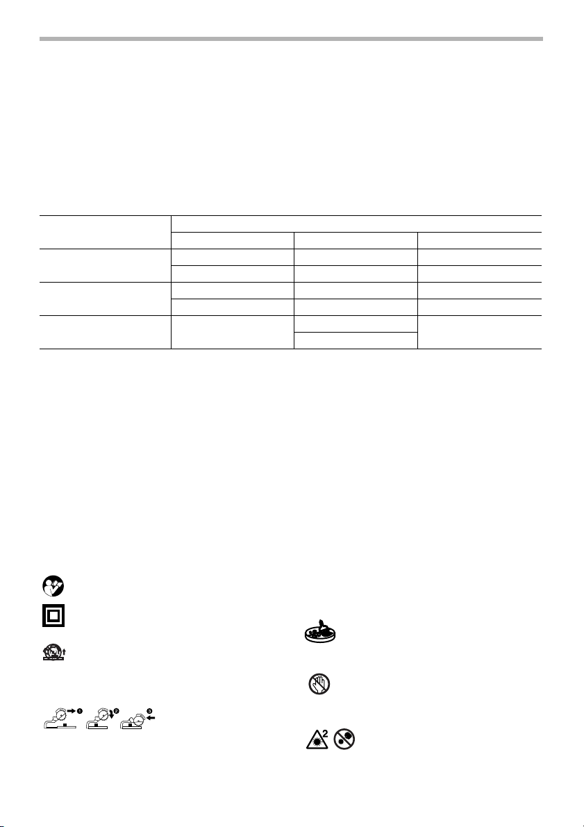
Symbols
The following show the symbols used for the tool. Be sure that you understand their meaning before use.
...................Read instruction manual.
...................DOUBLE INSULATION
...................To avoid injury from flying debris,
keep holding the saw head down,
after making cuts, until the blade has
come to a complete stop.
Bevel angle
* 75 mm x 142 mm Note 3
65 mm x 169 mm
fence. For your safety, remove chips,
small pieces, etc. from the table top
before operation.
................For your safety, remove chips, small
pieces, etc. from the table top before
operation.
................Do not place hand or fingers close to
the blade.
-----
END210-3
..............................When performing slide cut, first pull
carriage fully and press down handle,
then push carriage toward the guide
2
........Never look into the laser beam.
Direct laser beam may injure your
eyes.

..................Only for EU countries
Do not dispose of electric equipment
together with household waste material!
In observance of European Directive
2002/96/EC on waste electric and
electronic equipment and its implementation in accordance with
national law, electric equipment that
have reached the end of their life
must be collected separately and
returned to an environmentally compatible recycling facility.
Intended use
The tool is intended for accurate straight and miter cutting in wood. With appropriate saw blades, aluminum
can also be sawed.
Power supply
The tool should be connected only to a power supply of
the same voltage as indicated on the nameplate, and
can only be operated on single-phase AC supply. They
are double-insulated in accordance with European
Standard and can, therefore, also be used from sockets
without earth wire.
SAFETY INSTRUCTIONS ENA001-2
WARNING:
When using electric tools, basic safety precautions, including the following,
should always be followed to reduce the risk of fire, electric shock and
personal injury. Read all these instructions before operating this product
and save these instructions.
For safe operations:
1. Keep work area clean.
Cluttered areas and benches invite injuries.
2. Consider work area environment.
Do not expose power tools to rain. Do not use
power tools in damp or wet locations. Keep work
area well lit. Do not use power tools where there is
risk to cause fire or explosion.
3. Guard against electric shock.
Avoid body contact with earthed or grounded surfaces (e.g. pipes, radiators, ranges, refrigerators).
4. Keep children away.
Do not let visitors touch the tool or extension cord.
All visitors should be kept away from work area.
5. Store idle tools.
When not in use, tools should be stored in a dry,
high or locked up place, out of reach of children.
6. Do not force the tool.
It will do the job better and safer at the rate for which
it was intended.
7. Use the right tool.
Do not force small tools or attachments to do the job
of a heavy duty tool. Do not use tools for purposes
not intended; for example, do not use circular saws
to cut tree limbs or logs.
8. Dress properly.
Do not wear loose clothing or jewellery, they can be
caught in moving parts. Rubber gloves and non-skid
footwear are recommended when working outdoors.
Wear protecting hair covering to contain long hair.
9. Use safety glasses and hearing protection.
Also use face or dust mask if the cutting operation is
dusty.
10. Connect dust extraction equipment.
If devices are provided for the connection of dust
extraction and collection facilities ensure these are
connected and properly used.
11. Do not abuse the cord.
Never carry the tool by the cord or yank it to disconnect it from the socket. Keep the cord away from
heat, oil and sharp edges.
12. Secure work.
Use clamps or a vice to hold the work. It is safer
than using your hand and it frees both hands to
operate the tool.
13. Do not overreach.
Keep proper footing and balance at all times.
14. Maintain tools with care.
Keep cutting tools sharp and clean for better and
safer performance. Follow instructions for lubrication and changing accessories. Inspect tool cord
periodically and if damaged have it repaired by an
authorized service facility. Inspect extension cords
periodically and replace, if damaged. Keep handles
dry, clean and free from oil and grease.
3

15. Disconnect tools.
When not in use, before servicing and when changing accessories such as blades, bits and cutters.
16. Remove adjusting keys and wrenches.
Form the habit of checking to see that keys and
adjusting wrenches are removed from the tool
before turning it on.
17. Avoid unintentional starting.
Do not carry a plugged-in tool with a finger on the
switch. Ensure switch is off when plugging in.
18. Use outdoor extension leads.
When tool is used outdoors, use only extension
cords intended for outdoor use.
19. Stay alert.
Watch what you are doing. Use common sense. Do
not operate tool when you are tired.
20. Check damaged parts.
Before further use of the tool, a guard or other part
that is damaged should be carefully checked to
determine that it will operate properly and perform
its intended function. Check for alignment of moving
parts, free running of moving parts, breakage of
parts, mounting and any other conditions that may
affect its operation. A guard or other part that is
damaged should be properly repaired or replaced
by an authorized service center unless otherwise
indicated in this instruction manual. Have defective
switches replaced by an authorized service facility.
Do not use the tool if the switch does not turn it on
and off.
21. Warning.
The use of any accessory or attachment, other than
those recommended in this instruction manual or
the catalog, may present a risk of personal injury.
22. Have your tool repaired by a qualified person.
This electric tool is in accordance with the relevant
safety requirements. Repairs should only be carried
out by qualified persons using original spare parts,
otherwise this may result in considerable danger to
the user.
ADDITIONAL SAFETY RULES FOR TOOL ENB034-3
1. Wear eye protection.
2. Keep hands out of path of saw blade. Avoid con-
tact with any coasting blade. It can still cause
severe injury.
3. Do not operate saw without guards in place.
Check blade guard for proper closing before
each use. Do not operate saw if blade guard
does not move freely and close instantly. Never
clamp or tie the blade guard into the open position.
4. Do not perform any operation freehand. The
workpiece must be secured firmly against the turn
base and guide fence with the vise during all operations. Never use your hand to secure the workpiece.
5. Never reach around saw blade.
6. Turn off tool and wait for saw blade to stop
before moving workpiece or changing settings.
7. Unplug tool before changing blade or servicing.
8. Always secure all moving portions before carry-
ing the tool.
9. Stopper pin which locks the cutter head down is
for carrying and storage purposes only and not
for any cutting operations.
10. Don’t use the tool in the presence of flammable liq-
uids or gases.
11. Check the blade carefully for cracks or damage
before operation.
Replace cracked or damaged blade immediately.
12. Use only flanges specified for this tool.
13. Be careful not to damage the arbor, flanges (espe-
cially the installing surface) or bolt. Damage to
these parts could result in blade breakage.
14. Make sure that the turn base is properly secured so
it will not move during operation.
15. For your safety, remove the chips, small pieces, etc.
from the table top before operation.
16. Avoid cutting nails. Inspect for and remove all nails
from the workpiece before operation.
17. Make sure the shaft lock is released before the
switch is turned on.
18. Be sure that the blade does not contact the turn
base in the lowest position.
19. Hold the handle firmly. Be aware that the saw
moves up or down slightly during start-up and stopping.
20. Make sure the blade is not contacting the workpiece
before the switch is turned on.
21. Before using the tool on an actual workpiece, let it
run for a while. Watch for vibration or wobbling that
could indicate poor installation or a poorly balanced
blade.
22. Wait until the blade attains full speed before cutting.
23. Stop operation immediately if you notice anything
abnormal.
24. Do not attempt to lock the trigger in the on position.
25. Be alert at all times, especially during repetitive,
monotonous operations. Don’t be lulled into a false
sense of security. Blades are extremely unforgiving.
4

26. Always use accessories recommended in this manual. Use of improper accessories such as abrasive
wheels may cause an injury.
27. Do not use the saw to cut other than wood, aluminum or similar materials.
28. Connect miter saws to a dust collecting device
when sawing.
29. Select saw blades in relation to the material to
be cut.
30. Take care when slotting.
31. Replace the kerf board when worn.
32. Do not use saw blades manufactured from high
speed steel.
33. Some dust created from operation contains
chemicals known to cause cancer, birth defects
or other reproductive harm. Some examples of
these chemicals are:
• lead from lead-based-painted material and,
SAVE THESE INSTRUCTIONS
• arsenic and chromium from chemicallytreated lumber.
Your risk from these exposures varies, depending on how often you do this type of work. To
reduce your exposure to these chemicals: work
in a well ventilated area and work with approved
safety equipment, such as those dust masks
that are specially designed to filter out microscopic particles.
34. To reduce the emitted noise, always be sure that
the blade is sharp and clean.
35. The operator is adequately trained in the use,
adjustment and operation of the machine.
36. Use correctly sharpened saw blades. Observe
the maximum speed marked on the saw blade.
37. Refrain from removing any cut-offs or other
parts of the workpiece from the cutting area
whilst the tool is running and the saw head is
not in the rest position.
5
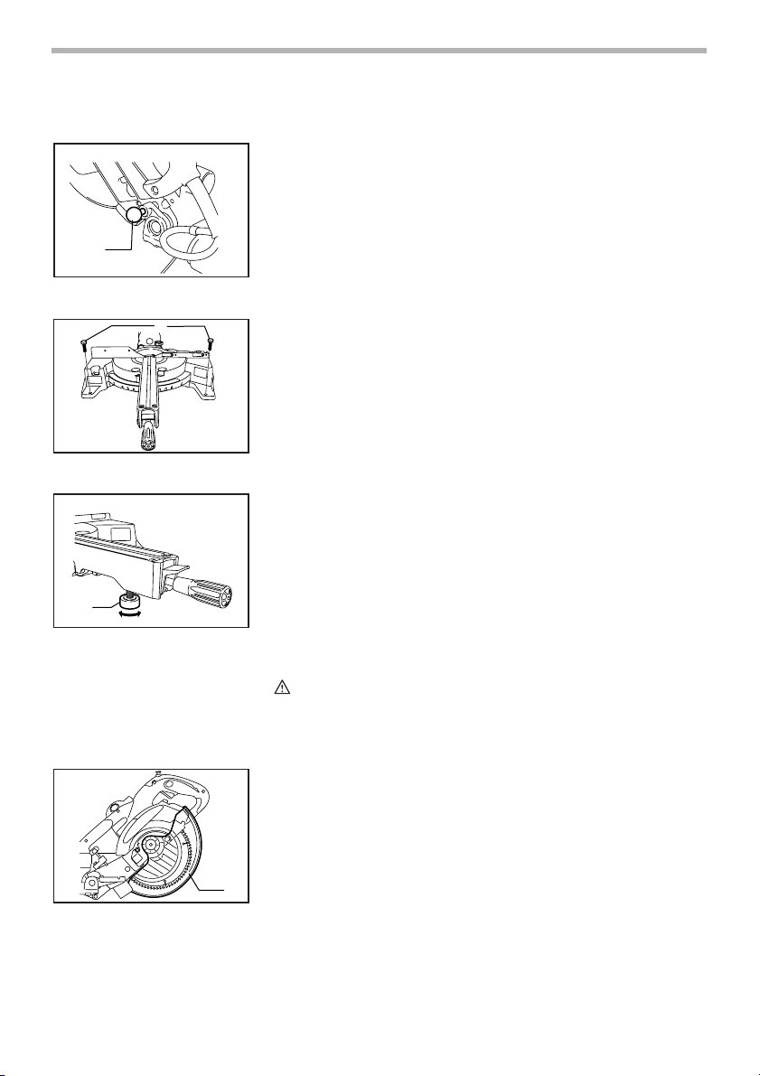
INSTALLATION
1
1. Stopper pin
1
1. Bolts
1
Bench mounting
006945
When the tool is shipped, the handle is locked in the lowered position by the
stopper pin. Release the stopper pin by lowering the handle slightly and pulling
the stopper pin.
006946
This tool should be bolted with two bolts to a level and stable surface using the
bolt holes provided in the tool’s base. This will help prevent tipping and possible injury.
006947
Turn the adjusting bolt clockwise or counterclockwise so that it comes into a
contact with the floor surface to keep the tool stable.
1. Adjusting bolt
FUNCTIONAL
DESCRIPTION
1. Blade guard
6
CAUTION:
• Always be sure that the tool is switched off and unplugged before
adjusting or checking function on the tool.
006992
Blade guard
When lowering the handle, the blade guard rises automatically. The guard is
spring loaded so it returns to its original position when the cut is completed
and the handle is raised. NEVER DEFEAT OR REMOVE THE BLADE GUARD
OR THE SPRING WHICH ATTACHES TO THE GUARD.
In the interest of your personal safety, always maintain the blade guard in good
condition. Any irregular operation of the blade guard should be corrected
immediately. Check to assure spring loaded return action of guard. NEVER
USE THE TOOL IF THE BLADE GUARD OR SPRING ARE DAMAGED,
1
FAULTY OR REMOVED. DOING SO IS HIGHLY DANGEROUS AND CAN
CAUSE SERIOUS PERSONAL INJURY.
If the see-through blade guard becomes dirty, or sawdust adheres to it in such
a way that the blade is no longer easily visible, unplug the saw and clean the
guard carefully with a damp cloth. Do not use solvents or any petroleum-based
cleaners on the plastic guard.
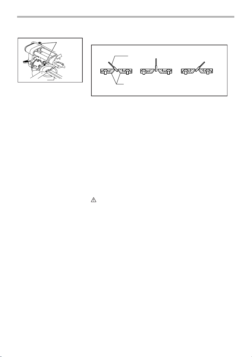
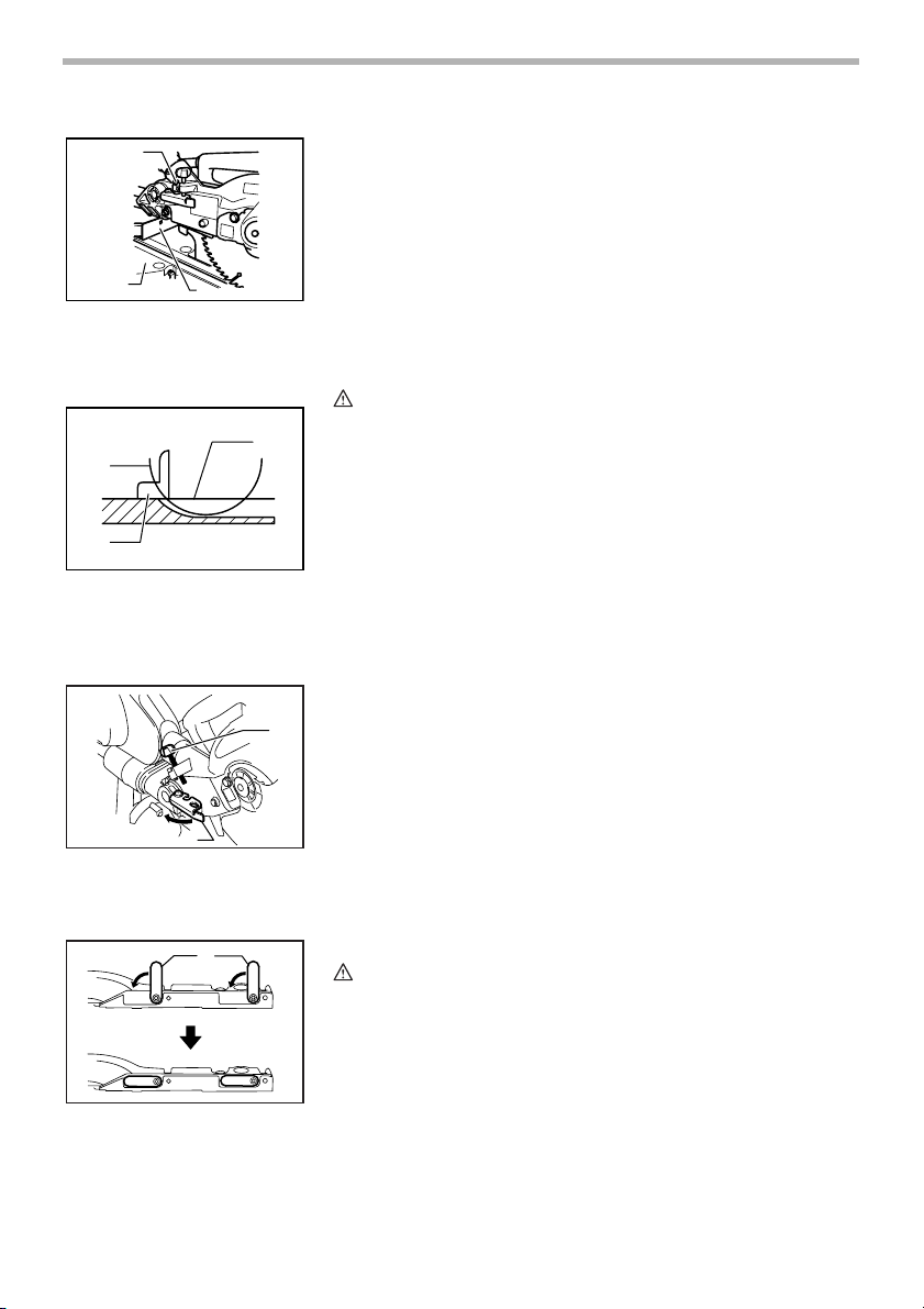
006951
Positioning kerf board
1
006952
1
1. Clamp screws
2. Kerf board
2
2
345
1. Saw blade 2. Kerf board
3. Left bevel cut 4. Straight cut
5. Right bevel cut
This tool is provided with the kerf boards in the turn base to minimize tearing
on the exit side of a cut. The kerf boards are factory adjusted so that the saw
blade does not contact the kerf boards. Before use, adjust the kerf boards as
follows:
First, unplug the tool. Loosen all the screws (2 each on left and right) securing
the kerf boards. Re-tighten them only to the extent that the kerf boards can still
be easily moved by hand. Lower the handle fully and push in the stopper pin to
lock the handle in the lowered position. Loosen two clamp screws which
secure the slide poles. Pull the carriage toward you fully. Adjust the kerf boards
so that the kerf boards just contact the sides of the blade teeth. Tighten the
front screws (do not tighten firmly). Push the carriage toward the guide fence
fully and adjust the kerf boards so that the kerf boards just contact the sides of
blade teeth. Tighten the rear screws (do not tighten firmly).
After adjusting the kerf boards, release the stopper pin and raise the handle.
Then tighten all the screws securely.
CAUTION:
• Before and after changing the bevel angle, always adjust the kerf boards
as described above.
7
1
2
3
1. Adjusting bolt
2. Turn base
3. Guide fence
2
3
1. Top surface of turn table
2. Periphery of blade
3. Guide fence
1
003927
Maintaining maximum cutting capacity
This tool is factory adjusted to provide the maximum cutting capacity for a
216 mm saw blade.
When installing a new blade, always check the lower limit position of the blade
and if necessary, adjust it as follows:
First, unplug the tool. Push the carriage toward the guide fence fully and lower
the handle completely. Use the socket wrench to turn the adjusting bolt until
the periphery of the blade extends slightly below the top surface of the turn
base at the point where the front face of the guide fence meets the top surface
of the turn base.
With the tool unplugged, rotate the blade by hand while holding the handle all
the way down to be sure that the blade does not contact any part of the lower
base. Re-adjust slightly, if necessary.
005516
CAUTION:
• After installing a new blade, always be sure that the blade does not
contact any part of the lower base when the handle is lowered
completely. Always do this with the tool unplugged.
006953
Stopper arm
The lower limit position of the blade can be easily adjusted with the stopper
arm. To adjust it, move the stopper arm in the direction of the arrow as shown
1
in the figure. Adjust the adjusting screw so that the blade stops at the desired
position when lowering the handle fully.
1. Adjusting screw
2. Stopper arm
1. Sub fence
8
2
006954
Mini sub fence
1
CAUTION:
• Before performing right bevel cuts, place the mini sub fence inside the
guide fence. Failure to do so may cause tool or saw blade to strike the
mini sub fence.
This tool is equipped with the mini sub fence which should ordinarily be positioned as shown in the figure. This provides wide guide support when performing right angle cut.

1
1. Sub fence
1
1. Sub fence
Guide fence has scale of every 10 mm increments. This acts as guide for cut-
006955
off piece.
007020
Sub fence
This tool is equipped with the sub fence which should ordinarily be positioned
as shown in the figure.
However, when performing left bevel cuts, set it to the left position as shown in
the figure.
007021
CAUTION:
• When performing left bevel cuts, flip the fence over to the left position as
shown in the figure. Otherwise, it will contact the blade or a part of the
tool, causing possible serious injury to the operator.
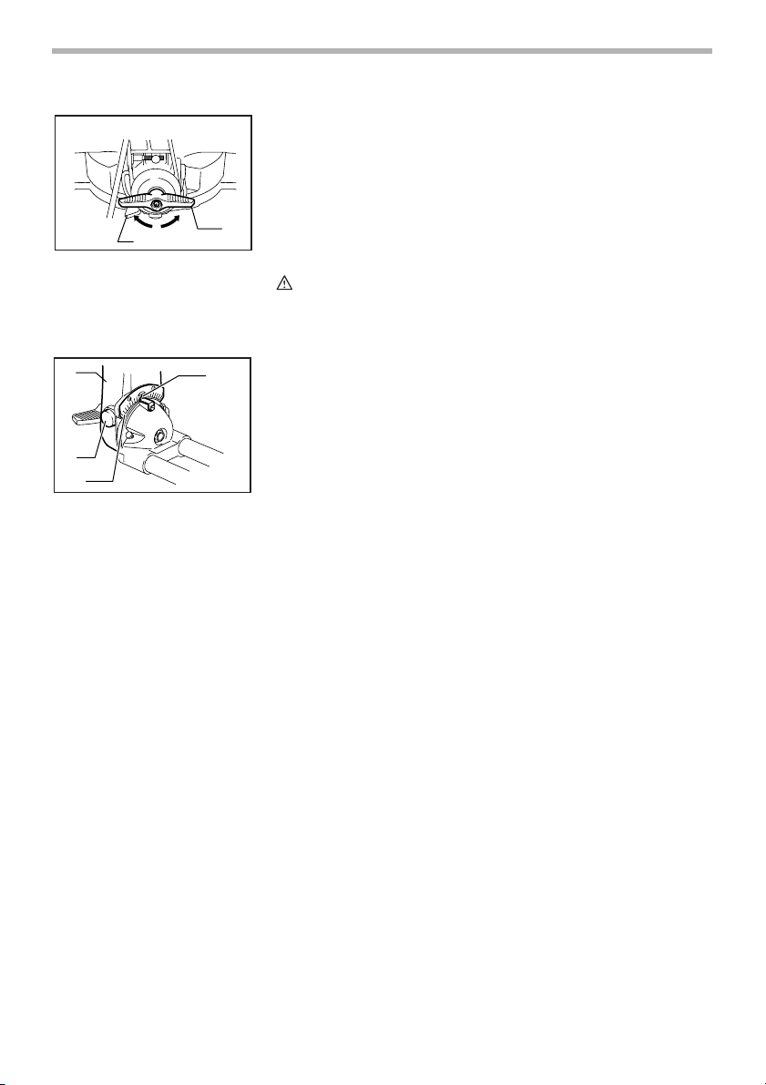
1
1. Turn base
2. Miter scale
3. Pointer
4. Grip
5. Lock lever
006956
Adjusting the miter angle
5
Loosen the grip by turning counterclockwise. Turn the turn base while pressing
down the lock lever. When you have moved the grip to the position where the
pointer points to the desired angle on the miter scale, securely tighten the grip
clockwise.
CAUTION:
3
2
4
• When turning the turn base, be sure to raise the handle fully.
• After changing the miter angle, always secure the turn base by tightening
the grip firmly.
9
1
2
1. Tighten
2. Clamping screw
3. Loosen
4. Lever
1
2
3
1. Arm
2. Release button
3. Bevel scale
4. Pointer
006957
Adjusting the bevel angle
To adjust the bevel angle, loosen the lever at the rear of the tool counterclockwise. At this time, make sure that the clamping screw is loosened. If not,
loosen it. Just loosening lever does not allow you to adjust the bevel angle.
Push the handle to the left to tilt the saw blade until the pointer points to the
desired angle on the bevel scale. Then tighten the lever clockwise firmly to
secure the arm.
3
To tilt the blade to the right, push the release button at the rear of the tool while
4
tilting the blade slightly to the left after loosening the lever. With the release
button depressed, tilt the saw blade to the right.
CAUTION:
• When tilting the saw blade, be sure to raise the handle fully.
• After changing the bevel angle, always secure the arm by tightening the
006958
4
lever clockwise.
• When changing bevel angles, be sure to position the kerf boards
appropriately as explained in the “Positioning kerf boards” section.
10
 Loading...