

Page 1
T
ECHNICAL INFORMATION
Models No.
LS0714, LS0714F, LS0714FL, LS0714L
PRODUCT
P 1 / 26
Description
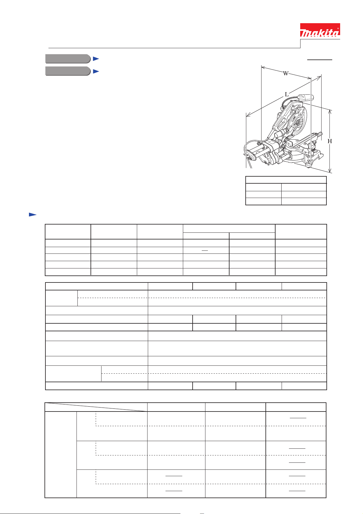
Slide Compound Saw 190mm (7-1/2")
CONCEPT AND MAIN APPLICATIONS
New slide compound saw model LS0714 has been developed to
improve cost-effectiveness by removing electronic circuit for soft start &
constant speed from model LS0713.
The primary use is for making/modifying interior decorations in apartment
building. Model LS0714's compact design and light weight are
convenient to carry to workplace.
The LS0714 series is available in the following variations:
*LS0714:With neither Fluorescent job light nor Laser marker
*LS0714F:With Fluorescent job light for cutting workpiece in dark places
*LS0714FL:With Fluorescent job light and Laser marker for easy trace of
cutting line
*LS0714L:With Laser marker
Specification
Voltage (V) Cycle (Hz)
110
120
220
230
240
Current (A)
9.7
10.0
4.8
4.6
4.4
50 / 60
50 / 60
50 / 60
50 / 60
50 / 60
Length ( L )
Width (W )
Height ( H )
Continuous Rating (W)
Input Output
1,010
1,010
1,010
1,010
450
450
450
450
Dimensions : mm ( " )
670 (26-3/8)
430 (17)
458 (18)
Max. Output(W)
1,200
1,200500
1,200
1,200
1,200
Model No.
Saw blade
No load speed: min-1= rpm.
Fluorescent job light
Laser marker
Lock-off botton for trigger switch
Electric brake
Protection against electric shock
Power supply
cord: m ( ft )
Net weight: kg ( lbs )
Cutting capacity: mm ( " )
Miter angle
Diameter: mm ( " )
Hole diameter: mm ( " )
Australia
Except Australia
Bevel angle
With a 20mm
auxiliary wood fence
90°
With a 15mm
auxiliary wood fence
45°
Left and Right
With a 10mm
auxiliary wood fence
57° Right
LS0714
20 (13/16) [Canada, Chile, Colombia, Mexico, Panama, USA: 15.88 (5/8)]
No
No No
12.5 (27.6) 12.8 (28.2) 13.1 (28.9)
45°
Left
45 x 265
(1-3/4 x 10-3/8)
40 x 300
(1-9/16 x 11-3/4)
45 x 185
(1-3/4 x 7-1/4)
40 x 212
(1-9/16 x 8-3/8)
LS0714F LS0714FL
190 (7-1/2)
6,000
Yes Yes
Yes
Yes
No
( for Canada and USA: Yes)
Double insulation
2.0 (6.6)
2.5 (8.2)
90°
60 x 265
(2-3/8 x 10-3/8)
52 x 300
(2-1/16 x 11-3/4)
60 x 185
(2-3/8 x 7-1/4)
52 x 212
(2-1/16 x 8-3/8)
60 x 145
(2-3/8 x 5-3/4)
52 x 163
(2-1/16 x 6-3/8)
LS0714L
No
Yes
12.8 (28.2)
5°
Right
40 x 300
(1-9/16 x 11-3/4)
Page 2

Standard equipment
T.C.T. Saw blade 190mm ............................... 1 pc
Socket wrench 10 ........................................... 1 pc
Dust bag ........................................................ 1 pc
Vertical vise ................................................... 1 pc
Note: The standard equipment for the tool shown may differ from country to country.
Holder set (2 pcs. in set) ......................................... 1 set
Triangular rule ........................................................ 1 pc
Hex wrench 2.5 (LS0714FL/ LS0714L only).......... 1 pc
Switch button ........................................................... 2 pcs
Optional accessories
Horizontal vise
Holder assembly
Set plate assembly
Various TCT saw blades
Holder assembly for supporting long stock
Fluorescent tube for LS0714F and LS0714FL
P 2 / 26
Page 3
P 3 / 26
Repair
WARNING: Be sure to unplug the tool before maintenance or repair.
See the instruction manual on how to handle the tool.
Remove the following parts from the machine for safety before repair/ maintenance:
*Saw Blade *Inner Flange *Outer Flange *Dust Nozzle
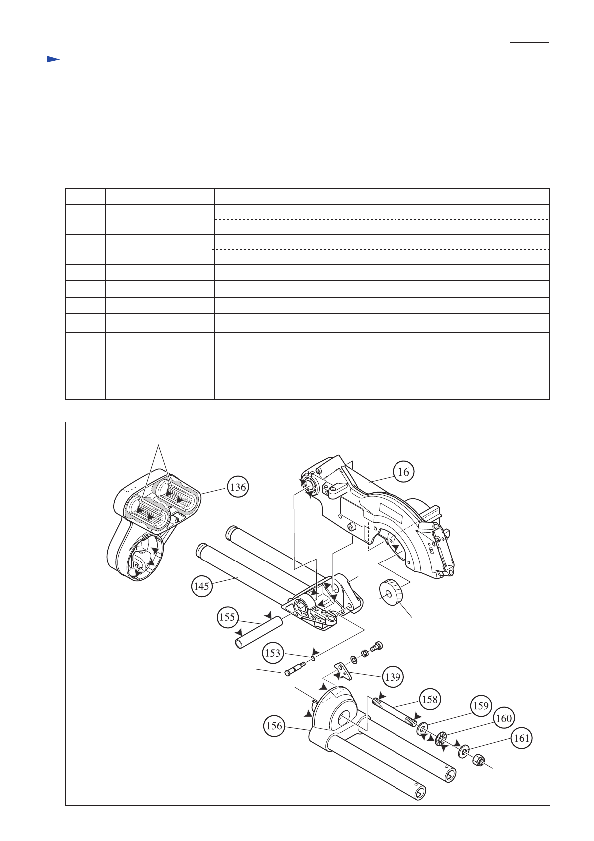
[1] Lubrication
1. Apply Makita grease N. No.1 to the following portions designated by black triangle to protect parts and product from
unusual abrasion. See Fig. 1.
Item No. Parts description
Blade case
16
136
139
145
158
159, 161
Fig. 1
Arm complete
Stopper plate
Front arm complete
O ring 5153
Pipe 16-90155
Arm holder156
Screw M10
Flat washer 10
Thrust needle gauge 1024 160
Linear ball bearing, factory-assembled
Portion to lubricate
Apply 6g to the gear room if the room has been washed for cleaning.
Both pivot portions where front arm (item No. 145) contacts
Inside of hole which accepts arm holder's (156) rib portion.
Linear ball bearing in which pipe portion of front arm (145) slides
Surface to which inner wall of arm holder (156) contacts
Pivot portion where blade case (16) contacts
Whole
Pipe ends to which axis holes of front arm complete (145) contact
Swivel portion where arm complete (136) contacts
Threads
Surfaces where thrust needle gauge 1024 (160) contacts
Head and reverse side to which washers 10 (159 and 161) contact
Stopper pin
Helical gear 47
Page 4
P 4 / 26
Repair
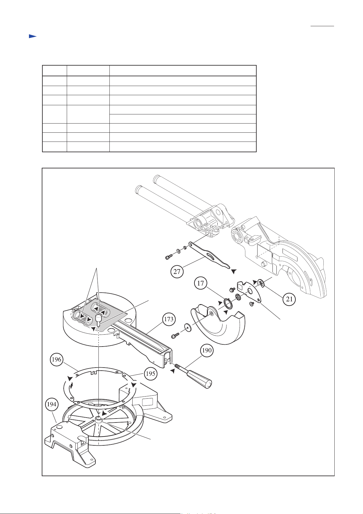
2. Apply Makita grease N. No.1 to the following portions designated by black triangle to protect parts and product from
unusual abrasion. See Fig. 2.
Item No. Parts item Portion to lubricate
Spiral spring 26 Whole
17
21 Center plate Portion where center cover contacts
27
173
190
194
195, 196
Fig. 2
Link plate
Turn base
Grip 32
Base
Slide plate The surface on which (173) turn base's edge slides
Tip round portion
Axis
Linear ball bearing in which arm holder's (156) pipe slides
Threads
The boss for accepting (173) turn base's axis
Factory-assembled
linear ball bearing
Axis of turn base
Center cover
Boss for accepting
the turn base's axis
Page 5
P 5 / 26
Repair
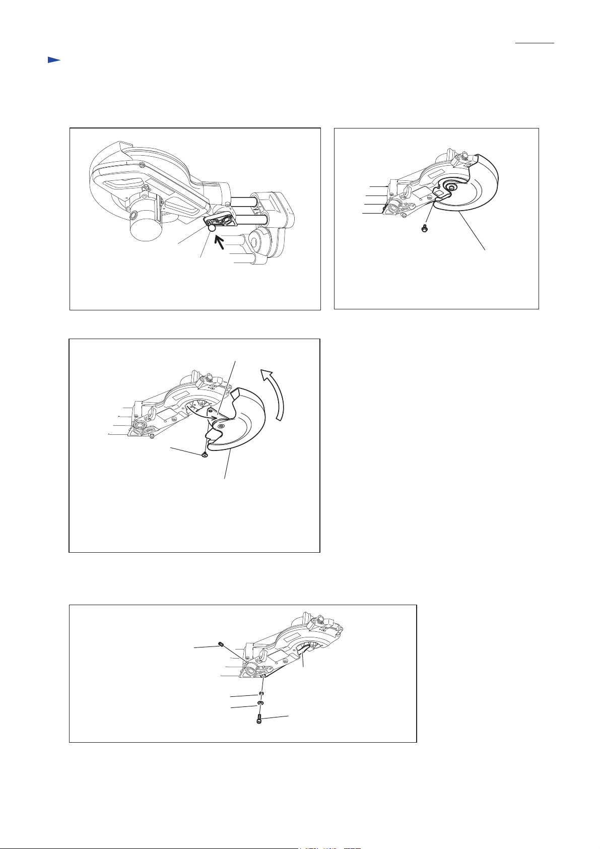
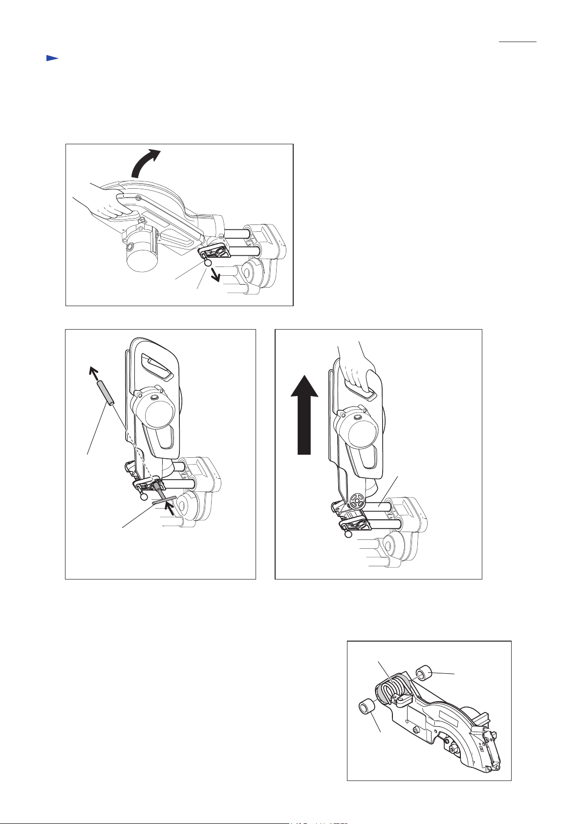
[2] Removing motor unit (blade case, motor housing, handle etc.) from front arm complete
1. Remove safety cover section from blade case as illustrated in Fig. 3-1, Fig.3-2 and Fig.3-3.
Fig. 3-1 Fig. 3-2
Stopper pin
Knob 20
Lock the motor unit by pushing knob 20 for stopper pin
while keeping the motor unit at the rest position.
Fig. 3-3
Center cover
+ Flat head screw M5
Safety cover
Turn safety cover and then open center cover as illustrated
above. + flat head screw M5 comes into sight at that time.
The safety cover section can be separated from motor unit
by removing the + flat head screw M5.
Hex bolt M6x14
Center cover
Remove hex bolt M6x14 from center cover.
2. Remove the screws in Fig. 3-4 to disconnect the linkage of motor unit and front arm complete.
Fig. 3-4
Hex socket headbolt M6x10
(for securing pipe16-90)
Link plate
Ring 6
Flat washer 6
Hex socket head bolt M6x20
(for fixing link plate)
Page 6
P 6 / 26
Repair
3. While holding the motor unit with your hand, pull out knob 20 for stopper pin to release the lock of motor unit, and
lift up the motor unit slowly until it comes to the free point from return force of torsion spring 28. See Fig. 3-5.
4. Remove pipe 16-90 by pushing it out using socket wrench 10. See Fig. 3-6.
5. Remove motor unit from front arm complete. See Fig. 3-7.
Fig. 3-5
Stopper pin
Knob 20
Fig. 3-6
Pipe 16-90
Socket wrench 10
Push out pipe 16-90 using socket wrench 10
as illustrated above.
Fig. 3-7
Front arm complete
[3] Mounting motor unit (blade case, motor housing, handle etc.) to front arm complete
1. Insert two sleeves 17 into torsion spring 28. See Fig. 4.
2. Mount the motor unit to front arm complete. Refer to Fig. 3-7.
3. Pass pipe 16-90 through the holes of front arm and blade case.
Refer to Fig. 3-6.
4. While keeping motor unit in the rest position, push knob 20 for
stopper pin toward the blade case side. Refer to Fig. 3-5.
5. Secure link plate with hex socket head bolt M6x20, and secure
the pipe 16-90 with ring 6, flat washer 6 and hex socket head screw
M6x10. Refer to Fig. 3-4.
Fig. 4
Torsion spring 28
Sleeve 17
Sleeve 17
Page 7
P 7 / 26
Repair
[5]Adjusting the return force of torsion spring 28
1. Torsion spring 28 should be adjusted so that motor unit can smoothly return to the initial raised position from any
other place.
Turning hex socket head set screw M6x16 with hex wrench allows to adjust the return force. See Fig. 5.
Fig. 5
Return force: Weak
Return force: Strong
Hex socket head set screw M6x16
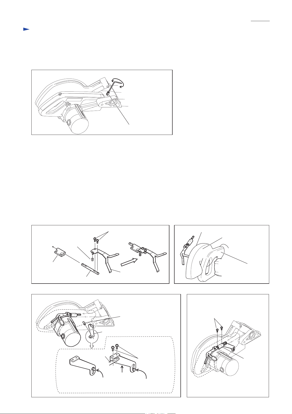
[6] Assembling safety lock mechanism
Note: The products for the following countries are equipped with safety lock mechanism.
* Europe * South Africa * China
1. Assemble the component parts of safety lock mechanism as illustrated in Fig. 6-1.
2. Holding the mounted compression spring 7 to lock lever, pass the lock lever through the loop portion of handle,
and bring the safety lock mechanism between handle and blade case complete. See Fig. 6-2.
3. Pass lock pin through the large hole of lock plate.And lift up lock plate in order to align its screw holes with those
of rod 8.Then, the lock pin's head comes to the keyhole slot of lock plate.And secure lock plate with pan head
screw M4x10 to rod 8. See Fig. 6-3.
4. Secure rod holder with tapping screw bind CT 4x16, while pressing it toward blade case complete in order to
make rod 8 parallel to handle as Fig. 6-4. Make sure that safety cover is locked with safety lock mechanism when
lock lever is in the original position.
Compression
spring 7
Rod holder
Rod 8
Rod 8
Pan head screw M4x10
Lock lever
Lock pin
Lock plate
Pan head screw
Fig. 6-2Fig. 6-1
Lock lever
Blade case complete
Handle
Fig. 6-4Fig. 6-3
Tapping screw
bind CT 4x16
Rod holder
Lock pin's head unlocked
in keyhole slot
Lock pin's head locked
in the keyhole slot
Page 8
Repair
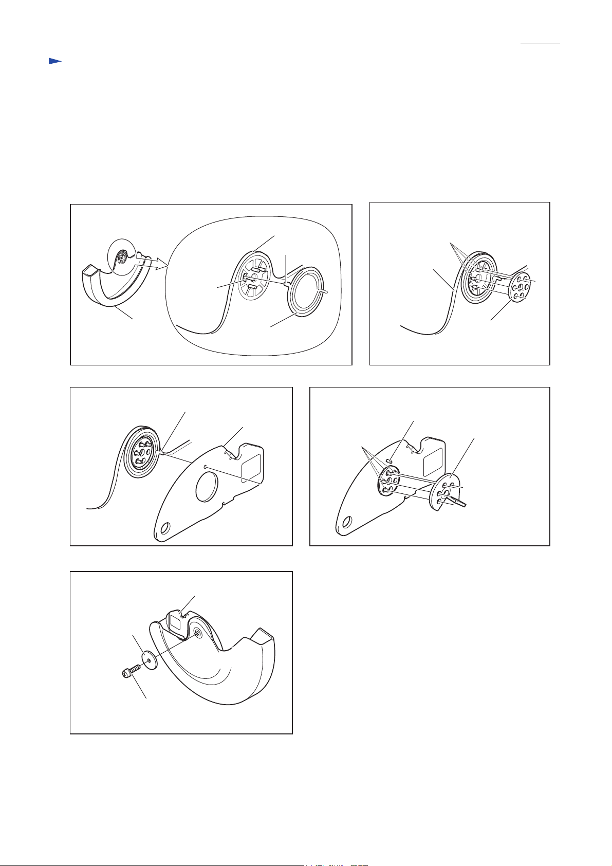
[7] Assembling safety cover section
1. Insert the tail portion of spiral spring 26 into the elliptical hole of safety cover. See Fig. 7-1.
2. Mount center washer to safety cover by aligning its holes with four bosses of safety cover. See Fig. 7-2.
3. Mount center cover by inserting the another tail portion of spiral spring 26 into the center cover's hole.
See Fig. 7-3.
4. Mount center plate to safety cover by fitting four bosses of safety cover into center plate's holes.
See Fig. 7-4.
5. Fix the assembled parts with pan head screw M5x18. See Fig. 7-5.
P 8/ 26
Fig. 7-1
Fig. 7-3
Safety cover
Elliptical
hole
Safety cover
Another tail portion of spiral spring 26
Spiral spring 26
Center cover
Tail portion
Fig. 7-4
Four Bosses
Fig. 7-2
Four Bosses
Safety cover
Center washer
Another tail portion
of spiral spring 26
Center plate
Fig. 7-5
Flat washer 5
Center cover
Pan head screw
M5x18
Page 9

P 9/ 26
Repair
[8] Removing turn base from base
1. Remove guide fence and kerf board. See Fig. 8-1.
2. Remove hex lock nut M8-13 using socket wrench.And then, remove turn base from base while pushing lock lever in
the direction designated with arrow. See Fig. 8-2.
Fig. 8-1
Hex socket headbolt M6x25
Guide fence
Tapping screw bind CT 4x12
Kerf board
Kerf board
Tapping screw bind
CT 4x12
Fig. 8-2
Turn base complete
Socket wrench
Hex lock nut M8-13
Flat washer 8
Base
Lock lever
Remove turn base from base complete
while pushing down lock lever.
Page 10

P 10/ 26
Repair
[9] Mounting turn base to base
1. Apply grease to slide plate and boss for accepting the turn base's axis. Refer to Fig. 2.
2. Fasten hex lock nut M8-13 so that the turn base can move smoothly without wobbling. Refer to Fig. 8-2.
[10] Mounting square rod and securing ring 26
1. Setting ring 26 to pipe 25-235 of arm holder complete, mount arm holder complete to turn base. See Fig. 9-1.
2. Slide arm holder complete so that each end of the two pipes come nearer to the axis of turn base. See Fig. 9-2.
3. Secure square rod to pipes of arm holder complete with hex bolt M5x30.
Fig. 9-1 Fig. 9-2
< Note > Rubber pin has to face
Pipe 25-235 of
arm holder complete
Ring 26
Hex bolt M5x30
arm mounted side.
Rubber pin
Hex bolt M5x30
Square rod
Turn base
Arm holder complete
<Note>
For easy mounting, slide ring 26 closely
to arm mounted side in this step.
4. Slide ring 26 toward turn base and align the following holes for thumb screw M6x33 and hex socket head bolt M4x10.
* Screw hole of turn base (upper side)
* Screw holes of ring 26
* Screw hole of turn base (bottom side)
And tighten thumb screw M6x33 to secure ring 26 to turn base. See Fig. 9-3.
5. Tighten hex socket head bolt M4x10 from the bottom side of turn base.
Then ring 26 is completely secured to turn base.
Fig. 9-3
Arm is mounted here.
Thumb screw M6x33
Axis of turn base
Arm is mounted
here.
Arm holder complete
Screw hole of turn base (upper side)
Screw hole of ring 26
Screw hole of turn base (bottom side)
Ring 26
Hex socket head bolt M4x10
Page 11

P 11/ 26
Repair
[11] Disassembling positive lock mechanism of turn base
1. Remove grip 32.
2. Separate lock lever plate and lock lever from turn base by removing tapping screw bind CT 4x16. See Fig. 10-1.
3. Turn lock pin in order to face pin 3 to vertical direction. And remove pin 3 while pushing compression spring 6
toward the grip side. See Fig. 10-2.
4. By pulling off lock pin from turn base, compression spring 6 can be removed from lock pin.
Fig. 10-1 Fig. 10-2
Grip 32
Lock lever plate
Lock lever
Tapping screw
bind CT 4x16
Pin 3
Compression
spring 6
Lock pin
[12] Assembling positive lock mechanism of turn base
Do the reverse of disassembling procedure with the following attention:
1. The protrusion of lock lever plate has to face the grip side.
2. Apply grease to the threaded portion of the grip.
See Fig. 11.
Fig. 11
Grip 32
Apply grease here.
Tapping screw bind CT 4x16
Projection of lock lever plate
Lock lever plate
Lock lever
Screw holes
Push compression spring in the direction
designated with arrow (toward grip side).
Page 12

Repair
[13] Mounting stopper plate to arm holder
Mount stopper plate as illustrated in Fig. 12.
Fig. 12
P 12/ 26
Arm holder
Stopper plate
Flat washer 6
Insert this tail into the small hole
of stopper plate.
Pan head screw M5
Torsion spring 8
[14] Mounting ring 26 and set screw M4x8
1. Insert ring 26 into the hole of arm. See Fig. 13.
2. Drive set screw M4x8 into the screw hole of arm by screwing thumb screw M6x33 with hex wrench.
Stop driving the set screw at the same time it reaches surface A.
Fig. 13
Thumb screw M6x33
Hex wrench
Screw hole for
thumb screw M6x33
Arm
Ring 26
Set screw M4x8
Arm holder
Stopper plate
Flat washer 6
Torsion
spring 8
Pan head
screw M5
Hex wrench
Set screw M4x8
Screw hole of
arm
Surface A
Ring 26
Arm
[15] Adjusting arm for smooth pivot action
1. Adjust hex lock nut M10x17 so that arm can pivot smooth without backlash. See Fig. 14-1.
2. Mount lever 100 and the relevant parts to arm with keeping the lever angle in lock position as Fig. 14-2.
Fig. 14-1 Fig. 14-2
Arm
Flat washer 10
Arm
Hex lock nut
M10-17
Arm holder
Approx 10° against
horizontal plane
Lever 100
Compression spring 5
Hex nut M10-17
Pan head screw M4x10
Page 13

Repair
[16] Angle adjustment of saw blade
1. Adjust the angle of saw blade at 90° against
While keeping this condition, fix the angle by adjusting 0
2. As for 45
After that the fix the angle by adjusting 0
° degrees adjusting, use 45 degrees set square as Fig. 15-3.
turn base using 90 degrees set square (Makita Part No.1R208). See Fig. 15-1.
° degrees bevel angle adjusting bolt
° degrees bevel angle adjusting bolt at the side of arm as Fig. 15-4.
P 13/ 26
at the side of arm. See Fig. 15-2.
Fig. 15-1
Fig. 15-3
45
°
1R208 : 90 degrees set square
90
°
1R207 : 45 degrees set square
Fig. 15-2
Arm
0
degrees bevel angle adjusting bolt
(Hex bolt M6x16)
Fig. 15-4
Arm
45
degrees bevel angle adjusting bolt
(Hex bolt M6x16)
90
°
45
°
[17] Adjustment for max. cutting capacity
Do the following steps to obtain the max. cutting capacity.
1. Pull the motor unit to your side until it stops.
2. Lower the motor unit until it stops.
3. And then adjust the Ø190mm saw blade so that it comes to the position shown in Fig. 16.
Note: The saw blade must not contact kerf boards and base, when the motor unit is in the lowest position.
4. Tighten hex bolt M6x16 using socket wrench 10.
Fig. 16
Socket wrench 10
(Standard equipment)
Hex bolt M6x16
ø190mm saw blade
Kerf board
Page 14

P 14/ 26
Repair
[18] Angle adjustment of guide fence
1. Provisionally tighten a M6x25 hex bolt into screw hole A on the operator's left side of guide fence as Fig. 17.
2. While checking the angle of guide rule to saw blade using 90 degrees set square (No.1R208), adjust the guide fence
by moving its right end until the angle sets at 90 degrees
3. After completion of squaring adjustment, securely tighten three M6x25 hex bolts in order of C, B, A.
Fig. 17
Hex bolt M6x25
.
C
Move this side.
Screw hole A is smaller
than Screw hole B/C.
A
90 degrees set square
(No.1R208)
B
Saw blade
Operator's position
[19] Disassembling laser section (exclusively for LS0714FL/ LS0714L)
1. Remove lock lever from rod 8 before disassembling laser section.
Refer to the chapter < 6 > "Assembling safety lock mechanism".
2. After removing thumb screw M5x24, remove top cover by taking off tapping screw bind CT4x20. See Fig. 18-1.
3. Take off laser line label which adheres on blade case, and remove shoulder screw M5 with which laser section is
secured on blade case.
Fig. 18-1
Tapping screw bind CT4x20
Flat washer 5
Thumb screw M5x24
Shoulder screw M5
Laser line label
4. Remove lead cover holder by unscrewing tapping screw bind CT4x20. Then, lead coverA and lead cover B can be
removed from blade case. See Fig. 18-2.
5. Disconnect socket unit of laser circuit from connector of lead unit.
6. Then, laser section can be removed from blade case.
Fig. 18-2
Lead cover holder
Lead cover B
Connector of
lead unit
Socket unit of
laser circuit
Tapping screw bind CT4x20
Lead cover A
Laser section
(Laser circuit, block B,
block C, etc.)
< Caution >
Be careful not to touch the lens for laser beam.
The laser beam irradiated through the smeared
lens becomes indistinct.
Top cover
Tapping screw bind CT4x20
Page 15

Repair
7. Laser section can be disassembled as shown in Fig. 18-3.
Fig. 18-3
1) Unscrewing pan head screw M3x10 allows
to remove torsion spring 9 and laser circuit.
Block C
Torsion spring 9
P 15/ 26
Block B
Pan head screw M3x10
2) Remove torsion spring 9 and block C
by unscrewing pan head screw M3x10.
Pan head screw
M3x10
Laser circuit
Torsion spring 9
[20] Assembling laser section (exclusively for LS0714FL/ LS0714L)
1. Mount torsion spring 9 and block B to block C and secure them with pan head screw M3x10. Refer to Fig. 19-1.
Make sure that block C and block B can move in torsional direction.
2. Mount torsion spring 9 and laser circuit to block B, and secure them with pan head screw M3x10. Refer to Fig. 18-3.
Make sure that block B and laser circuit can move in torsional direction. See Fig. 19-2.
Fig. 19-1
Block C
Torsion spring 9
Fig. 19-2
Block C
Block B
Pan head screw M3x10
3. For easy adjustment of irradiated angle of laser beam from now on, drive hex socket set screws M4x6 until their
head portions come to the same level with the surfaces of block C and laser circuit. See Fig. 19-3.
4. Hold the lead wires of laser circuit between two ribs of block C. See Fig. 19-4.
Fig. 19-3
Block C
Block C
Hex socket
set screw M4x6
Hex socket
set screw M4x6
Laser circuit
Block B
Hex socket
set screw M4x6
Laser circuit
Torsion spring 9
Laser circuit
Fig. 19-4
Ribs
Block C
Laser circuit
Page 16

P 16/ 26
Repair
WARNING: Special attention should be taken to the adjustment because plugging the tool is
required. Don't turn on the main switch for cutting operation of the tool while
adjusting the laser line position. Turn on the switch of laser beam only.
Never look into the laser beam. Direct laser beam may injure your eyes.
(1) Mechanism for adjustment of the position of laser line
1.Adjustment of the position of laser line can be made with the following screws which are under laser line label.
* Hex socket set screw M4x6 (A): for adjusting 90° to turn base See Fig.20-A
* Hex socket set screw M4x6 (B): for adjusting 90° to guide fence See Fig. 20-B
Fig. 20-1
Saw blade
By sliding the position of thumb screw M5x24, user can
select that the laser line is put down either the right side
Laser line
of blade or the left side.
Laser line label
Fig. 20-A Fig. 20-B
Hex socket set screw M4x6 (A)
The position of laser line
adjusted to 90° against
guide fence
Turn base
< Note > The position of laser line is factory adjusted in advance within 1mm from the sidesurface of blade.
(2) Precise adjustment of laser line
1. Lock the motor unit at the initial position.Mount "Jig for laser line adjustment" (Makita part No. 1R315) to spindle
and drive hex bolt M6x18 into the screw hole of spindle head. See Fig. 20-2.
Fig. 20-2
Hex socket set screw M4x6 (B)
Guide fence
The position of laser line
adjusted to 90° against
guide fence
Hex bolt M6x18
(for securing saw blade)
Jig for laser line adjustment (1R315)
Page 17

P 17/ 26
Repair
2. Make precise adjustment so that the laser line should be aligned with the line of jig for laser line adjustment (1R315)
when lowering the jig until it reaches the pan head screw M5x16 of link plate side. See Fig. 20-3.
Fig. 20-3
Link plate
Link plate
Pan head screw
M5x16 of link plate side
3.When lifting up the jig for laser line adjustment (1R315) until it reaches the pan head screw M5x16 of the laser box side,
be sure to make precise adjustment as Fig. 20-4.
Fig. 20-4
Jig for laser line
adjustment (1R315)
Line of jig for laser
line adjustment (1R315)
laser line should be aligned
with the line of jig.
Bearing box
Bearing box
Jig for laser line
adjustment (1R315)
Laser box
Line of jig
laser line should be aligned
with the line of jig for laser
line adjustment.
Pan head screw
M5x16 of laser
box side.
Page 18

P 18/ 26
Repair
(3) Adjustment of laser beam positioning (exclusively for LS0714FL/ LS0714L)
For safety and easy adjusting work, remove saw blade, safety cover section, flanges (outer and inner) and dust
nozzle.
1. Mount Jig for laser line adjustment (1R315) to spindle. See Fig. 20-2.
2. Tear away a part of laserline label until hex socket head set screws M4x6 (A and B) come into your sight as Fig.20-5.
3. Connect the machine with power source, and turn on the switch of laser. See Fig. 20-5.
4. Slide the position of thumb screw M5x24 to the center point for the movable range in order to reserve the adjustment
range to be wide. After that, drive the thumb screw M5x24 to fix the laser section.
Fig. 20-5
Switch of
laser beam
Laser line label
Slide the position of
thumb screw M5x24
to the center point for
the movable range.
Hex socket set
screw M4x6 (A)
5. Lower the jig until it reaches the pan head screw M5x16 of link plate side. See Fig. 20-3.
6. Move the laser line to the closest position to the line of jig by adjusting with hex socket set screw M4x6(A).
See Fig. 20-6.
Fig. 20-6
Hex socket set
screw M4x6 (A)
Be sure to turn hex wrench
Line of jig
clockwise and slowly in
order to avoid backlash.
Hex socket set
screw M4x6 (B)
Laser line at the closest
position to the line of jig.
Page 19

Repair
7. Lift up the jig until it reach the pan head screw M5x16 of laser box side. See Fig. 20-4.
8.Adjust the laser line so as to parallel the line of jig by turning hex socket set screw M4x6 (B). See Fig. 20-7.
Fig. 20-7
Laser box
Hex socket set
screw M4x6 (B)
Be sure to hex wrench
clockwise and slowly in
Line of jig for laser line
adjustment (1R315)
Laser line adjusted so as to
parallel the line of jig
order to avoid backlash
of screw.
P 19/ 26
9. In order to move the laser line onto the line of jig for laser line adjustment, slide the position of thumb screw M5x24
to left or right as Fig. 20-8. Finally driveThumb screw M5x24 to fix the laser section.
Fig. 20-8
Thumb screw M5x24
Line of jig for
laser line adjustment (1R315)
Laser line aligned
with the line of jig
Page 20

Repair
10. Lower the jig again until it reaches the pan head screw M5x16 of link plate side. See Fig. 20-6.
11. Align the laser line with the line of jig by turning hex socket set screw M4x6 (A). See Fig. 20-9.
Fig. 20-9
Hex socket head
set screw M4x6 (A)
Line of jig for laser line
adjustment (1R315)
Laser line aligning
with the line of jig
Be sure to turn hex wrench
clockwise and slowly in order
to avoid backlash of screw.
12. Lift up the jig again until it reaches the pan head screw M5x16 of laser box side. See Fig. 20-7.
13. Align the laser line with the line of jig by turning hex socket set screw M4x6 (B). See Fig. 20-10.
P 20/ 26
Fig. 20-10
Hex socket set screw M4x6 (B)
Line of jig for laser
line adjustment (1R315)
Laser line aligning
with the line of jig
Be sure to turn hex wrench
clockwise and slowly in order
to avoid backlash of screw.
14. Repeat the steps 9, 10, 11, 12 and 13, until the laser line aligns with the line of jig as illustrated in Fig. 20-3 and
Fig. 20-4.
Caution: Laserline label should be pasted again after adjustment.
This prevents dust from invading into the laser circuit and hex socket set screws M4x6 (A and B).
Page 21

Wiriing of Lead Wire to Terminal Block
(For all the subject models)
P 21/ 26
When connecting power supply cord with electrical
parts in handle, strip the power supply cord to expose
50mm up to 70mm of one inner lead wire for
connecting with Terminal as illustrated to right.
Terminal block
Circuit diagram
LS0714FL (with Fluorescent light and laser marker)
Color index of lead wires' sheath
Black
White
Red
(1) (2)
Orange
Blue
(3)
(4)
Powers supply cord
50-70mm
Brush
holder A
Brush
holder B
(5)
(9)
(10)
(1) Power supply cord
(2) Main switch
(3) Insulated connector
(4) Noise suppressor
Laser section
(11)
Power source
(5)Terminal block
(6) Connectors
(7) Light assembly
(8) Support complete
(Red or purple)
(6)
(12)
(9) Laser switch
(10) Receptacle
(11) Transformer
(12) Printed wiring board
(8)
(7)
(13)
(6)
(13) Laser circuit
Page 22

Wiring diagram in Handle L
LS0714FL (with Fluorescent light and laser marker)
P 22/ 26
Receptacles for connecting
to laser switch
Main switch
Noise suppressor
Printed wiring board
Rib B
Rib A
TransformerInsulated connector
Rib D
Connector
Punched
hole
Power supply cord
Rib C
Terminal block
Motor housing
1
Pass the lead wires (black and red) of wiring board
through the punched hole.
The following lead wires for connecting insulated
2
connector should be put into lead wire holder so that
insulated connector does not rise from handle L.
* Lead wire (red) to switch
* Lead wire (blue) to transformer
* Lead wire (blue) to light assembly
* Field lead wire (orange)
* Lead wire (white) of noise suppressor
Transformer must be mounted so that lead wires
3
(black and white) face the side of handle R and
are in the side of motor housing.
If these lead wires go over Rib A/B, these are pinched
between the Rib A/B and handle R.
Therefore, fix them with full attention.
4 When putting the lead wires into lead wire holders,
the thin lead wires have to be put under the thick
lead wires so as not to rise from the original position.
5
Power supply cord should be put so that its sheath
portion is between Rib C and the wall of housing L.
When putting handle R on housing L,
6
be careful not to go over lead wires on Rib D.
Otherwise it will happen pinching.
7
When connecting receptacles to laser switch,
be sure to face its wire-accepting side to handle R.
The receptacle with blue colored lead wire should
be close to I mark on the laser switch.
The receptacle with black colored lead wire should
be close to O mark on the laser switch.
See illustration below.
Wire-accepting side
Handle R
Lead wire
(blue)
Lead wire
(black)
Receptacles
Laser
switch
Page 23

Circuit diagram
LS0714F (with Fluorescent light)
Color index of lead wires' sheath
Black
White
Red
P 23/ 26
Orange
Blue
(1) (2)
(5)
(1) Power supply cord
(2) Main switch
(3) Insulated connector
(4) Noise suppressor
Wiring diagram in handle L
LS0714F (with Fluorescent light)
Main switch
(3)
(6)
(5) Terminal block
(6) Connectors
(4)
(7)
Brush
holder A
(8)
(7) Light assembly
(8) Support complete
Power supply cord
Brush
holder B
Noise suppressor
Boss
Insulated
connector
The following lead wires for connecting insulated connector
should be put into lead wire holder so that insulated connector
does not rise from handle L.
* Lead wire (red) to switch
* Lead wire (blue) to light assembly
* Field lead wire (orange)
* Lead wire (white) of noise suppressor
All lead wires have to be put on the right side of boss.
2
Rib C
Terminal block
Motor housing
Put field lead wires (orange) into lead wire holder
3
so that their wires do not sag in the motor housing.
4
When putting the lead wire into lead wire holders,
the thin lead wires have to be put under the thick
wires so as not to rise from the original position.
5
Power supply cord should be put so that its sheath
portion is between Rib C and the wall of housing L.
Page 24

Circuit diagram
LS0714 (without Fluorescent light and laser)
Color index of lead wires' sheath
Black
White
Orange
(1) Power supply cord
(2) Main switch
(3) Noise suppressor
(4) Support complete
Brush
holder A
P 24/ 26
Brush
holder B
Wiring diagram in handle L
LS0714 (without Fluorescent light and laser)
Main switch
Noise suppressor
Boss
Power supply cord
Rib C
Motor housing
All lead wires have to be put on the right side of boss.
1
2
Put field lead wires (orange) into lead wire holder so that their wires do not sag in the motor housing.
These lead wires have to be put into lead wire holder.
3
Power supply cord should be put so that its sheath portion is between Rib C and the wall of housing L.
4
Page 25

Circuit diagram
LS0714L (with laser marker)
Color index of lead wires' sheath
Black
White
Red
P 25/ 26
Orange
Blue
(1) (2)
(5)
(9)
(10)
(1) Power supply cord
(2) Main switch
(3) Insulated connector
(4) Noise suppressor
(5) Terminal block
(6) Connectors
(8) Support complete
Laser section
(11)
Power source
(12)
(4)
(3)
(6)
(9) Laser switch
(10) Receptacle
(11) Transformer
(12) Printed wiring board
Brush
holder A
Brush
holder B
(8)
(13)
(13) Laser circuit
Page 26

Wiring diagram in Handle L
LS0714L (with laser marker)
P 26/ 26
When connecting power supply cord with electrical
parts in handle, strip the power supply cord to expose
50mm up to 70mm of one inner lead wire for
connecting with Terminal as illustrated to right.
Printed wiring board
Rib D
Main switch
Noise suppressor
Connector
Punched
hole
Rib B
Rib A
Powers supply cord
Terminal block
50-70mm
Receptacles for connecting
to laser switch
Power supply cord
Rib C
Terminal block
Insulated connector
Pass the thin lead wires (black and red) with connector
1
of wiring board through the punched hole.
The following lead wires for connecting insulated
2
connector should be put into lead wire holder so thati
nsulated connector does not rise from handle L.
* Lead wire (red) to switch
* Lead wire (blue) to transformer
* Field lead wire (orange)
* Lead wire (white) of noise suppressor
Transformer must be mounted so that lead wires
3
(black and white) face the side of handle R and
are in the side of motor housing.
If these lead wires go over Rib A/B, these are pinched
between the Rib A/B and handle R.
Therefore, fix them with full attention.
4
When putting the lead wires into lead wire holders,
the thin lead wires have to be put under the thick
lead wires so as not to rise from the original position.
Transformer
Motor housing
5
Power supply cord should be put so that its sheath
portion is between Rib C and the wall of housing L.
6 When putting handle R on housing L,
be careful not to go over lead wires on Rib D.
Otherwise it will happen pinching.
7
When connecting receptacles to laser switch,
be sure to face its wire-accepting side to handle R.
The receptacle with blue colored lead wire should
be close to I mark on the laser switch.
The receptacle with black colored lead wire should
be close to O mark on the laser switch.
See illustration below.
Wire-accepting side
Handle R
Lead wire
(blue)
Lead wire
(black)
Receptacles
Laser
switch
 Loading...