

Makita LM430D, LM430DZ, LM430DWB, LM430DWBE, BLM430Z Technical Information
...
Model No.
Description
PRODUCT
CONCEPT AND MAIN APPLICATIONS
BLM430, LM430D
430mm Cordless Lawn Mower
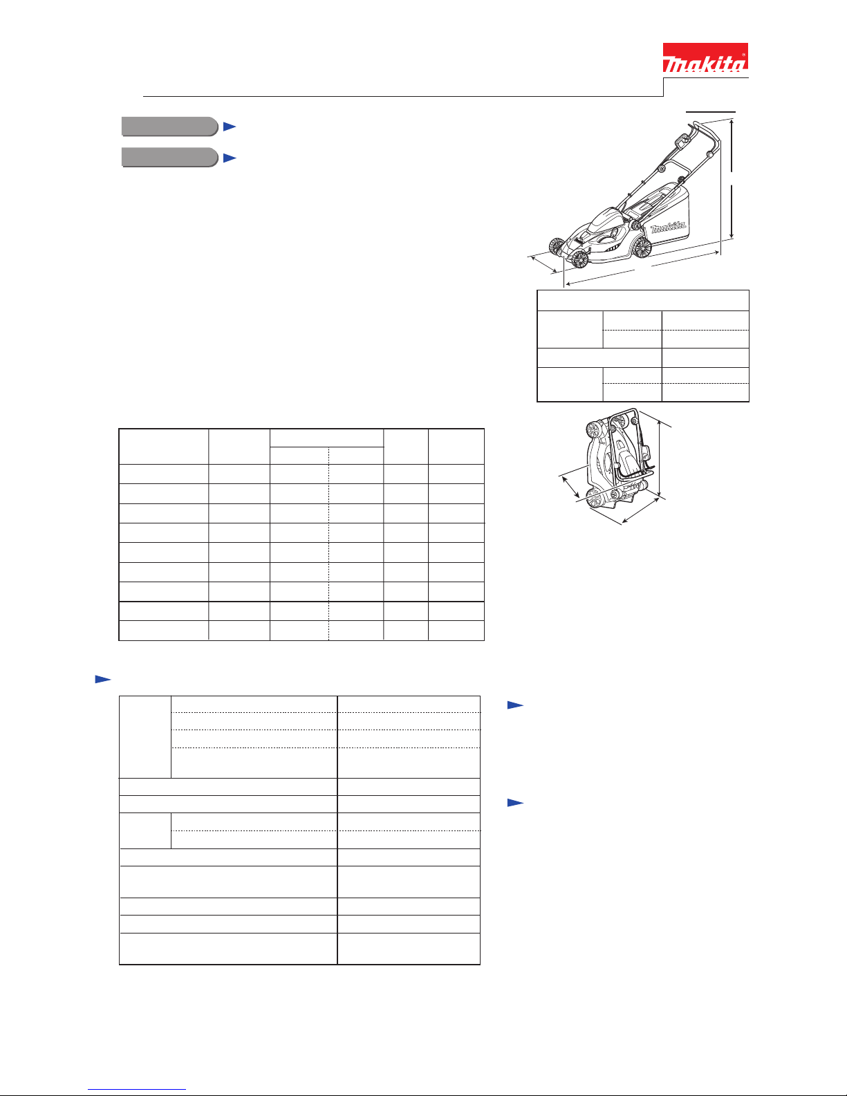
460 (18-1/8)
Dimensions: mm (inch)
Width (W)
Height (H)
Length (L)
1,490 (58-3/4)
1,450 (57)
950 (37-1/2)
1,020 (40-1/4)
T
ECHNICAL INFORMATION
maximum
minimum
maximum
minimum
P 1/ 8
Specification
Standard equipment
Optional accessories
Note: The standard equipment for the tool
shown above may vary by country.
Battery
Charging time (approx.): min.
Soft start
Weight according to
EPTA-Procedure 01/2003*
3: kg (lbs)
Capacity: Ah
Cell
Voltage: V
36V
No load speed: min.
ˉ¹=rpm*2
Yes
Electric brake Yes
18.1 (39.9)*
4,
17.9 (39.4)*5
2.2/ 2.6
Li-ion
580
60 with DC36WA/
22 with DC36RA
3,600
Max output (W)
Socket wrench ........................................ 1
Blade 430 .............................................. 1
Models LM430D, BLM430, (HML01)*
1 is Cordless Lawn mower equipped
with rotary blade cutting system.
Its main benefits are:
• Environment-friendly with zero emission and minimum noise pollution
• Compatible with both Makita 36V-2.6Ah Li-ion battery BL3626
and 36V-2.2Ah Li-ion battery BL3622A
• Compatible with Battery converters, BCV01 and BCV02
• Adjustable 13 cutting heights from 20mm to 75mm
• The storage space can be saved by standing the machine on its rear
end (See illustrated right.)
• Handle height is adjustable in 2 stages
This product is available in the variations listed below.
H
W
Battery 3622A
Battery BL3626
Charger DC36WA
Fast charger DC36RA
Battery converter BCV01
Battery converter BCV02
L
Cutting width: mm (") 430 (17)
20 - 75 (13/16 - 2-15/16),
13 stages
Cutting height adjustment range: mm (")
*2: No load speed of the cutting tool
*3: with battery, blade, grass bag
*4: for North and Central American countries
*5: All countries except North and Central American countries
Rotary type 2 tooth blade
Blade
Type
24.0 (15/16)Inner diameter: mm (")
LM430DWBE
Model No.
Type Quantity
Battery
converter
Battery
cover
Battery
BLM430Z
NoLM430DZ
No No
BLM430RD 1 No
No
BLM430RDE 2BL3626 1
BLM430ZX2C No No
HML01C1*
1 1
No
No
Charger
No
BL3622A 1 NoDC36WA
BL3622A 2 1DC36WA
DC36RA
No
BL3622ADC36WA
No
No
BCV02
No
HML01Z*
1 No NoNoNo No
No
No
LM430DWB
No NoNo NoNo
DC36RA BL3626
Note: All models also include the accessories listed below of "Standard equipment".
810 (32)
(without Rear bag)
460 (18-1/8)
490~500
(19-1/4~19-3/4)
Repair
P 2/ 8
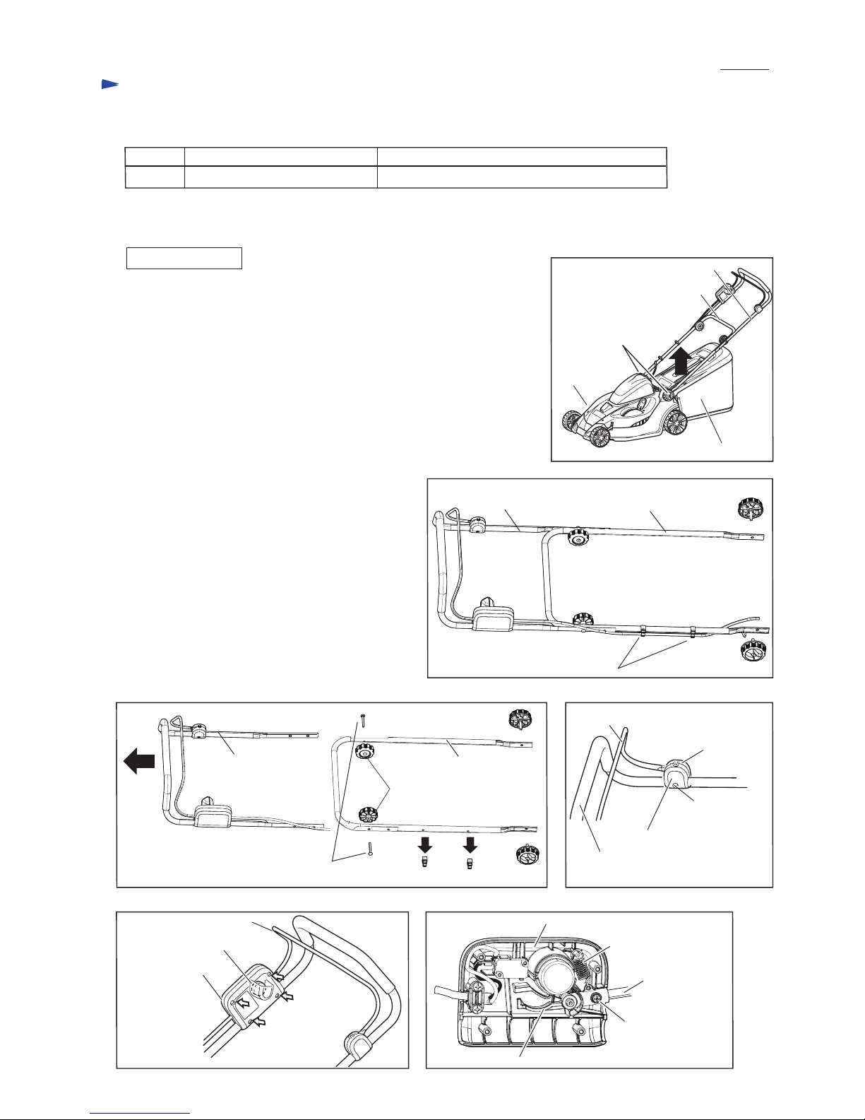
[2] ASSEMBLY/ DISASSEMBLY
[2]-1. Handle section
[1] NECESSARY REPAIRING TOOLS
DescriptionCode No. Use for
Round bar for Arbor 11-50
(1) Lift and remove Rear bag section from Deck. (Fig. 1)
While holding Handle section (Lower pipe, Upper pipe complete, etc.),
loosen two M6 Thumb screws. (Fig. 1)
Handle section is removed. (Fig. 2)
(2) Remove two Holders 9-19 from Lower pipe.
Remove two M6 Thumb nuts and M6x50 two Cup hex square neck bolts,
and then separate Upper pipe complete from Lower pipe. (Fig. 3)
Lower pipe can be replaced.
(3) Loosen 4x18 Tapping screw, then remove Switch lever case and
Switch lever case cover. (Fig. 4)
(4) Loosen four 4x18 Tapping screws, then remove Switch box cover complete
and Switch box. (Fig. 5)
(5) Remove Tension spring 9, and then separate Lever
and M4x20 Pan head screw with WR (spring washer
and Flat washer) from Switch box and Switch lever.
Upper pipe complete and Lever can be replaced.
(Fig. 6)
1R285
DISASSEMBLING
removing Plane bearing 10 from Front/ Rear wheels
CAUTION: Repair the machine in accordance with “Instruction manual” or “Safety instructions”.
Fig. 1
Fig. 2
Fig. 3
Fig. 5 Fig. 6
Fig. 4
Lower pipe
Rear bag complete
Deck
M8x35 Thumb screw
(2 pcs.)
Upper pipe complete
Switch lever
Switch box
Switch box cover complete
4x18 Tapping
screw (4 pcs.)
4x18 Tapping
screw
Switch lever case cover
Switch lever case
Switch lever
Lower pipeUpper pipe complete
M8x35 Thumb
screw
M8x35
Thumb screw
Holder 9-19 (2 pcs.)
Lower pipe
M6 Thumb nut
(2 pcs.)
Upper pipe complete
Upper pipe complete
Holder 9-19 (2 pcs.)
M6x50 Cup hex square neck bolt
Tension spring 9
Switch lever
Switch box
Lever
M4x20 Pan head
screw with WR
Repair
P 3/ 8
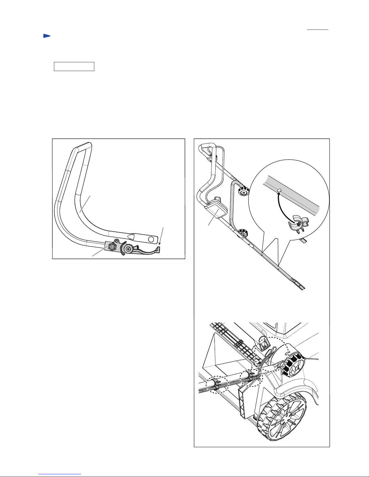
[2] ASSEMBLY/ DISASSEMBLY
[2]-1. Handle section (cont.)
Assemble Handle section in the reverse order of disassembly.
Note: • Face the top of Lever to the upper side when assembling Lever to Switch lever. (Fig. 7)
While holding the insert nut on lever so as not to separate, assemble Lever to Switch lever with M4x20 Pan head
screw with WR.
• Be careful to the direction of Compression spring 9. Refer to Fig. 6 in the previous page.
• Assemble Lower pipe to Upper pipe complete so that the two holes of Lower pipe come to Switch box side. (Fig. 8)
• Route Power supply cord along Lower pipe, and fix it in the lower holders of two Holders 9-19, then pass it over
Lower pipe near the hinge. (Fig. 8)
ASSEMBLING
Fig. 7 Fig. 8
The holes of Lower pipe
to attach Holders 9-19
The top of Lever
faces the upper side.
Switch lever
Switch box
LeverInsert nut
Holder 9-19
 Loading...